Communication

Automatic Estimation of Tropical Cyclone Centers from Wide-Swath Synthetic-Aperture Radar Images of Miniaturized Satellites

1
College of Ocean and Earth Sciences, Xiamen University, Xiamen 361005, China
2
State Key Laboratory of Marine Environmental Science, Xiamen University, Xiamen 361005, China
3
Key Laboratory of Underwater Acoustic Communication and Marine Information Technology, Ministry of Education, Xiamen University, Xiamen 361005, China
*
Authors to whom correspondence should be addressed.
Appl. Sci. 2024, 14(16), 7047; https://doi.org/10.3390/app14167047 (registering DOI)
Submission received: 10 July 2024 / Revised: 5 August 2024 / Accepted: 8 August 2024 / Published: 11 August 2024
(This article belongs to the Topic Radar Signal and Data Processing with Applications)

Abstract

:
Synthetic-Aperture Radar (SAR) has emerged as an important tool for monitoring tropical cyclones (TCs) due to its high spatial resolution and cloud-penetrating capability. Recent advancements in SAR technology have led to smaller and lighter satellites, yet few studies have evaluated their effectiveness in TC monitoring. This paper employs an algorithm for automatic TC center location, involving three stages: coarse estimation from a whole SAR image; precise estimation from a sub-SAR image; and final identification of the center using the lowest Normalized Radar Cross-Section (NRCS) value within a smaller sub-SAR image. Using three wide-swath miniaturized SAR images of TC Noru (2022), and TCs Doksuri and Koinu (2023), the algorithm’s accuracy was validated by comparing estimated TC center positions with visually located data. For TC Noru, the distances for the three stages were 21.42 km, 14.39 km, and 8.19 km; for TC Doksuri—14.36 km, 20.48 km, and 17.10 km; and for TC Koinu—47.82 km, 31.59 km, and 5.42 km. The results demonstrate the potential of miniaturized SAR in TC monitoring.

1. Introduction

With the intensification of global climate change, tropical cyclones (TCs) have become one of the significant challenges faced globally. TCs are intense cyclonic systems originating over tropical or subtropical waters, causing extensive loss of life and property. Therefore, accurately monitoring and forecasting the location and intensity of TCs are crucial for effectively reducing human casualties and economic losses. Particularly, precisely estimating the TC center is key [1,2,3].
Due to their broad coverage and high imaging rate, visible and infrared sensors have been widely used to monitor TCs [4]. These sensors have facilitated the development of various methods for TC-center estimation, such as the logarithmic-spiral curve-fitting algorithm [5], genetic algorithm [6], chaos immune evolutionary algorithm [7], ellipse curve model [8], brightness–temperature gradient-based algorithm [9], and weight slice method [10]. These methods are based on the morphological characteristics of TCs in visible and infrared imagery; however, visible and infrared sensors can only record the cloud-top manifestations of TCs. Since the TC center positions near the sea surface and at the cloud top are often uncoordinated [11,12], it is necessary to estimate the TC center positions near the sea surface.
In recent years, Synthetic Aperture Radar (SAR) has become a powerful tool for monitoring TCs with the advantages of all-time and all-weather application and high spatial resolution [13,14]. SAR can provide critical information such as the surface wind field and TC center position [15]. This information is vital for assessing the TC intensity and potential destructiveness [16,17]. Nonetheless, the long revisit cycles of SARs, such as the 24-day cycle of RADARSAT-2 and the 6-day cycle of Sentinel-1A/B, limit their capacity for timely monitoring TCs [12]. With advancements in sensor technology, SAR is evolving toward miniaturization. Compared to traditional large SAR satellite missions, miniaturized SARs are characterized by their lower weight and cost, and they are easier to form constellations [18]. This leads to shorter revisit cycles. Therefore, miniaturized SARs hold significant potential for timely monitoring TCs.
Typically, the Normalized Radar Cross-Section (NRCS) values are lower at the center of a TC compared to its surrounding areas in SAR imagery. This discrepancy facilitates the TC-center estimation by analyzing NRCS values. However, some phenomena associated with TCs, such as rainbands, also exhibit lower NRCS values in SAR imagery. Hence, relying solely on NRCS values is not robust for TC-center estimation. In the literature, various methods for estimating TC centers from SAR images have been proposed, including wavelet analysis [19], watershed segmentation [20], morphological analysis [21], and a particle swarm optimization algorithm [22]. Nonetheless, most of these methods are semi-automatic, requiring manual intervention. Hereafter, [23] proposed a fully automatic approach that estimates the TC center position by calculating the convergence degree of lines perpendicular to the inflow-angle-adjusted TC wind directions. With the rise of artificial intelligence (AI), there has been related research in TC-center estimation. For instance, in [24], deep learning techniques were employed to achieve automatic TC-center estimation in Sentinel-1 SAR images.
Due to the relatively recent launch of the HISEA series of miniaturized satellites, the number of TC images captured is limited. This scarcity of data makes it difficult to provide a sufficient training dataset for AI-based TC-center estimation methods. Therefore, this study applied the algorithm proposed by [23] on three wide-swath miniaturized SAR images. The objective is to investigate the potential of miniaturized SAR in estimating TC centers and to discuss the robustness of this automatic TC-center estimation algorithm. The algorithm is organized into three stages: Stage 1, Stage 2, and an optional stage, detailed in Section 3 and [23]. For clarity, the estimated TC center positions from Stage 1, 2, and the optional stage are named the coarsely estimated center position, the precisely estimated center position, and the NRCS-adjusted center position, respectively.
The remainder of this paper is organized as follows. Section 2 introduces the parameters of the SAR images and the TCs. Section 3 introduces the automatic TC-center estimation algorithm. Section 4 presents the results of TC-center estimation. Section 5 presents the discussion. Section 6 presents the Conclusion.

2. Miniaturized SAR Images

HISEA-1, the first miniaturized SAR in the HISEA series, was launched on 22 December 2020. Despite its compact weight of only 185 kg, HISEA-1 can deliver high-quality SAR images with a spatial resolution of 1 m and a swath width of up to 100 km [18]. The subsequent satellites in the series, Chaohu-1 and Fucheng-1, each weigh approximately 300 kg and were launched on 27 February 2022 and 7 June 2023, respectively. Currently, a number of studies have shown that HISEA-1 performs well in several important applications, including sea surface wind retrieval [25], ocean wave retrieval [26], floodwater segmentation [27], and ship detection [28]. These capabilities are crucial for accurate environmental monitoring and disaster assessment, enhancing our ability to respond to natural disasters and monitor maritime activities.
Operating at the C-band frequency with single VV-polarization (vertical transmit and vertical receive), these miniaturized SAR systems support four distinct imaging modes: StripMap, Spotlight, TOPSAR, and ScanSAR (including Narrow ScanSAR and Extra ScanSAR). The StripMap and Spotlight modes offer swath widths ranging from 20 km to 25 km, suitable for detailed, high-resolution imaging. In contrast, the TOPSAR and ScanSAR modes provide broader coverage—with swath widths between 80 km and 100 km—by utilizing multiple sub-swaths. This broader coverage, however, comes at the expense of slightly reduced imaging quality.
The data products generated by these satellites are classified into two primary levels: Level-1 single look complex (SLC) and Level-2 orthorectification geolocation (ORG) images. The Level-2 ORG images are derived from the Level-1 SLC images through processes that include radiometric calibration and terrain correction. This ensures that the ORG images have a spatial resolution of 10 m by 10 m for both ScanSAR and TOPSAR modes, balancing high resolution with extensive coverage. All three SAR images used in this study are Level-2 products. The specific TCs captured in these images include TC Noru, TC Doksuri, and TC Koinu. TC Noru was imaged on 23 September 2022 at 13:23 UTC, and at that time, it was classified as a Tropical Storm according to the standards set by the China Meteorological Administration (CMA). TC Doksuri was captured on 23 July 2023 at 01:36 UTC, also classified as a Tropical Storm. TC Koinu, however, was observed on 04 October 2023 at 02:41 UTC and intensified to a Severe Typhoon, indicating a much stronger and more intense storm system.
The specific parameters of these SAR images, along with the corresponding details of the TCs, are summarized in Table 1. This table includes information such as the classification of each TC, the imaging time, the spatial resolution of each SAR image, the imaging modes, the satellite orbit direction, and the location of the TC.

3. The Procedure of TC Center Estimation

If a TC exhibits a circular wind pattern, the perpendicular lines of the sea surface wind directions (SSWDs) all pass through the TC center. However, the actual wind patterns of TCs are characterized by spiral formations rather than perfect circles, resulting in SSWDs to deviate inward from the expected circumferential orientation. These deviations are commonly referred to as inflow angles [29]. The inflow angles for a TC in an SAR image are unknown. Hence, the algorithm applied in this study employs a series of compensation angles to offset the deviation of the sea surface wind directions (i.e., inflow angles). It then identifies the TC center position that yields the highest concentration of the perpendicular lines of compensated SSWDs.
The flowchart of the TC-center estimation algorithm is shown in Figure 1, and the specific procedures are clarified in Section 3.1, Section 3.2, and Section 3.3.

3.1. Stage 1: Coarse Estimation

(1)
Determining SSWD points and candidate points: Given that the TC center might fall outside the SAR image’s coverage, a candidate area larger than the SAR image coverage is defined. Initially, the SAR image’s width and height are denoted as ΔLon and ΔLat, respectively. A grid of SSWD points is then created using an interval of m1, resulting in a grid size of Δ L o n m 1 × Δ L a t m 1 . Subsequently, a candidate area centered on the SAR image’s center is defined with a width of 2ΔLon and a height of 2ΔLat. A grid of candidate points is generated within this expanded area using an interval of M1, leading to a total grid size of 2 Δ L o n M 1 × 2 Δ L a t M 1 . In this study, both m1 and M1 are set to 0.01°. It is important to note that the SSWDs are retrieved from the image slices centered on SSWD points, and the TC center position is determined from these candidate points;
(2)
SSWD retrieval and quality control: SSWD retrieval from SAR images is typically based on wind streak information. The scale of these wind streaks usually ranges from several kilometers to over ten kilometers. Consequently, centered on these points, image slices with dimensions of 1000 × 1000 pixels are extracted from the original SAR image. The SSWDs are then retrieved from these image slices by the improved local gradient (ILG) method [30]. Subsequently, slide a (2A + 1) × (2A + 1) window over the SSWD points and for the SSWD point (i, j), calculate
S = ( sin 2 θ i , j i = A , i i A j = A , j j A sin 2 θ i , j ( 2 A + 1 ) 2 1 ) 2 + ( cos 2 θ i , j i = A , i i A j = A , j j A cos 2 θ i , j ( 2 A + 1 ) 2 1 ) 2
where θ i , j represents the retrieved SSWD. In this stage, A is set to 5, and the SSWD is removed if S > 0.5   or   S < 0.001 . The variable S represents the dispersion of the SSWD. A higher S value indicates greater variability in the SSWDs within the window, whereas a lower S value suggests more consistency. Therefore, we set maximum and minimum thresholds of 0.5 and 0.001, respectively, for S to remove outliers;
(3)
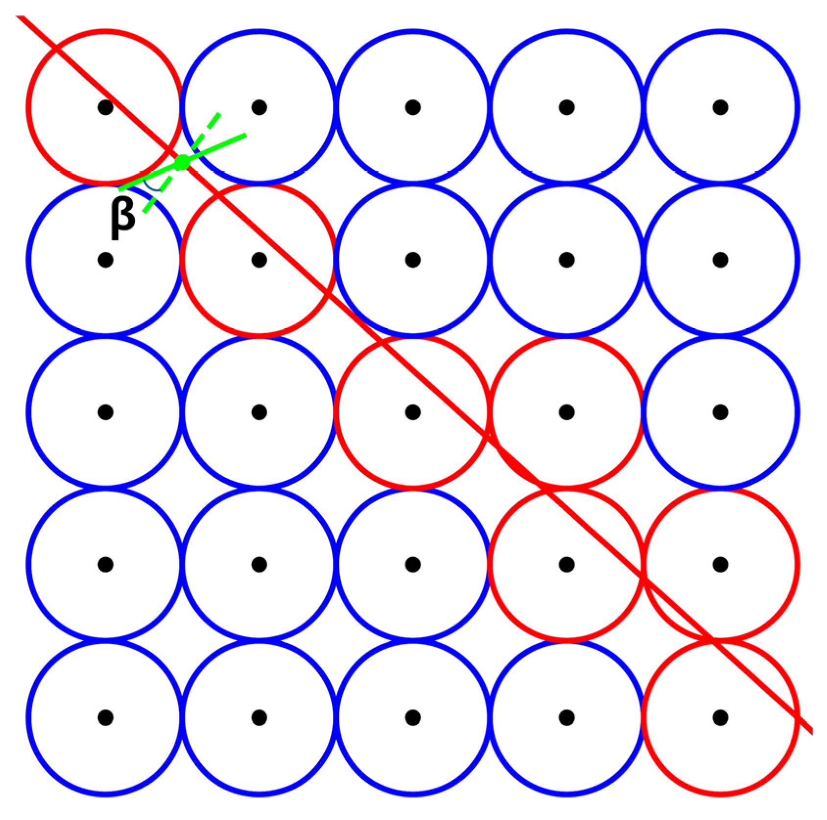
Estimating the TC center position: A total of 121 compensation angles within [−50°, 10°] were set at an interval of 0.5°. For each compensation angle, the retrieved SSWD is adjusted by adding the compensation angle. Subsequently, the perpendicular lines of these compensated SSWDs are calculated, and the number of these perpendicular lines passing through each candidate point is counted. As illustrated in Figure 2, if the distance from a candidate point to a line is less than M1/2, the line is considered to pass through the candidate point. It should be noted that the rule for determining whether a line passes through a point is different from that in [23].
This procedure described above is repeated for each of the 121 compensation angles, generating a corresponding set of heatmaps. The values on each heatmap correspond to the number of perpendicular lines passing through each candidate point. As shown in Figure 3, the local maximum values on these heatmaps vary with the compensation angles, where the curve’s peak value denotes the global maximum value across all heatmaps. The position associated with this peak value on the corresponding heatmap is the location of the coarsely estimated TC center.

3.2. Stage 2: Precise Estimation

(1)
Determining SSWD points and candidate points: Centered on the coarsely estimated TC center position, a sub-SAR image with a coverage of L1° × L1° is extracted from the original SAR image. At this stage, the coverage of the candidate area is also L1° × L1°. Subsequently, employing intervals of m2 and M2, grids for SSWD points and candidate points are created, resulting in grid sizes of L 1 m 2 × L 1 m 2 and L 1 M 2 × L 1 M 2 , respectively. In this stage, L1 is set to 1.2°, m2 to 0.01°, and M2 to 0.005°;
(2)
SSWD retrieval and quality control: Centered on these points, image slices with dimensions of 1000 × 1000 pixels are extracted from the sub-SAR image. The SSWDs are then retrieved from these image slices by the ILG method. Subsequently, Equation (1) was used to remove outliers of retrieved SSWDs. In this stage, A is set to 5, and the SSWD is removed if S > 0.5   or   S < 0.001 ;
(3)
Estimating the TC center position: A total of 121 compensation angles within [−50°, 10°] were set at an interval of 0.5°. For each compensation angle, the retrieved SSWD is adjusted by adding the compensation angle. Subsequently, the perpendicular lines of these compensated SSWDs are obtained, and the number of these perpendicular lines passing through each candidate point is counted.

3.3. Optional Stage: NRCS-Adjusted Estimation

Centered on the precisely estimated TC center position, a sub-SAR image with a coverage area of L2° × L2° is extracted from the original SAR image. Subsequently, the position corresponding to the lowest NRCS value in this sub-image is designated as the NRCS-adjusted TC center position. In this stage, L2 is set to 0.6°.
It should be noted that L1 and L2 were separately chosen as 1.2° and 0.6° based on two main criteria: first, to ensure that the sub-SAR images cover the TC eye area as completely as possible, and second, to optimize computational efficiency. These parameters are suitable for other TCs as well. Additionally, these values are not fixed at 1.2° or 0.6° and can be adjusted based on the criteria.

4. Results

Figure 3 reveals the variation in maximum values across 121 heatmaps corresponding to 121 compensation angles for TC Noru, TC Doksuri, and TC Koinu, respectively. In the figure, the blue solid lines and orange dashed lines represent the local maximum values in each heatmap for Stage 1 and Stage 2 of the estimation process, respectively. As illustrated in the figure, the global maximum values for Stage 1 and Stage 2 occur at distinct compensation angles for each TC. For TC Noru, the global maximum values are observed at a compensation angle of 0.5° in Stage 1 and −0.5° in Stage 2. For TC Doksuri, the global maximum values shift more significantly, occurring at −16.5° in Stage 1 and −27.5° in Stage 2. Similarly, for TC Koinu, the global maximum values are found at −17.5° in Stage 1 and −23.0° in Stage 2. These observations highlight the adaptability and iterative improvement of the TC-center estimation algorithm across different compensation angles. The distinct compensation angles at which the global maximum values occur for each TC demonstrate the algorithm’s responsiveness to the unique characteristics of each storm. By iteratively refining the compensation angle, the algorithm achieves higher accuracy in the TC-center estimation, illustrating its robustness and effectiveness in handling varying TC structures and intensities.
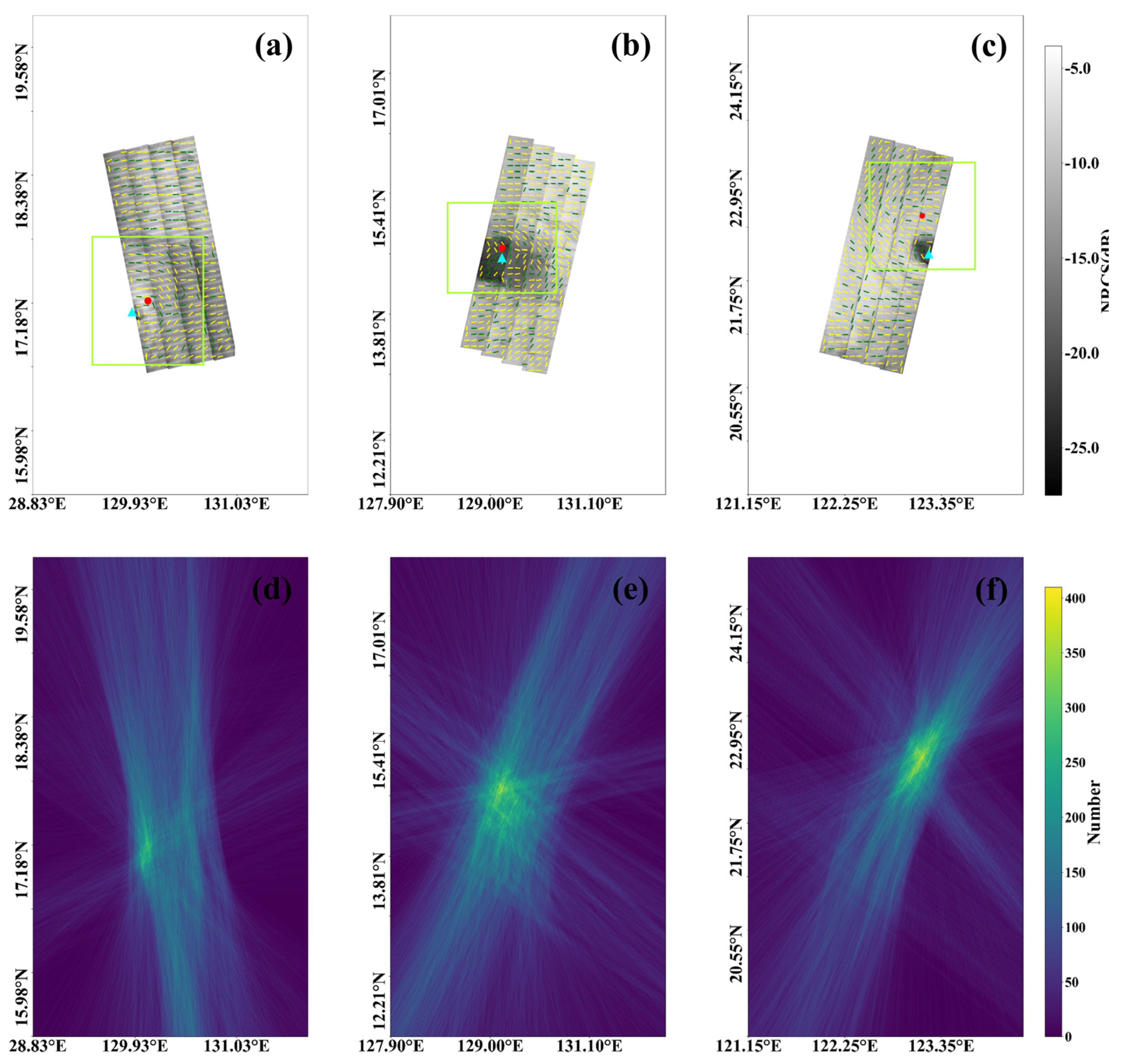
As shown in Figure 4a–c, the entire area for each sub-figure represents the corresponding candidate area, which is larger than the coverage of the corresponding SAR image. This broader candidate area allows for a more robust determination of the TC center by encompassing all potential locations within the SAR image’s vicinity. The coarsely estimated center positions of TCs Noru, Doksuri, and Koinu are denoted as red points, providing an initial approximation based on the algorithm’s Stage 1 estimation process. The removed SSWDs, which are considered less reliable or less relevant for TC-center estimation, are represented by green lines. In contrast, the remaining SSWDs, which contribute to the TC center position, are denoted by yellow lines. The visually located TC center positions, used as ground truth to assess the accuracy of the algorithm-estimated TC center positions, are indicated by cyan triangles. Each sub-figure also includes a sub-SAR image, highlighted within green boxes. These sub-images are used to precisely estimate the TC center position in Stage 2. By focusing on a smaller, more targeted area within the larger candidate region, the algorithm can achieve greater precision in identifying the exact TC center position. Figure 4d–f display the heatmaps corresponding to the compensation angles of 0.5°, −16.5°, and −17.5°, respectively, for TCs Noru, Doksuri, and Koinu. The location of the maximum value in each of the three heatmaps corresponds to the coarsely estimated TC center position, as determined in Stage 1 of the algorithm. These maximum values indicate the points where the initial estimation aligns closely with the true TC center, setting the stage for further refinement in subsequent stages.
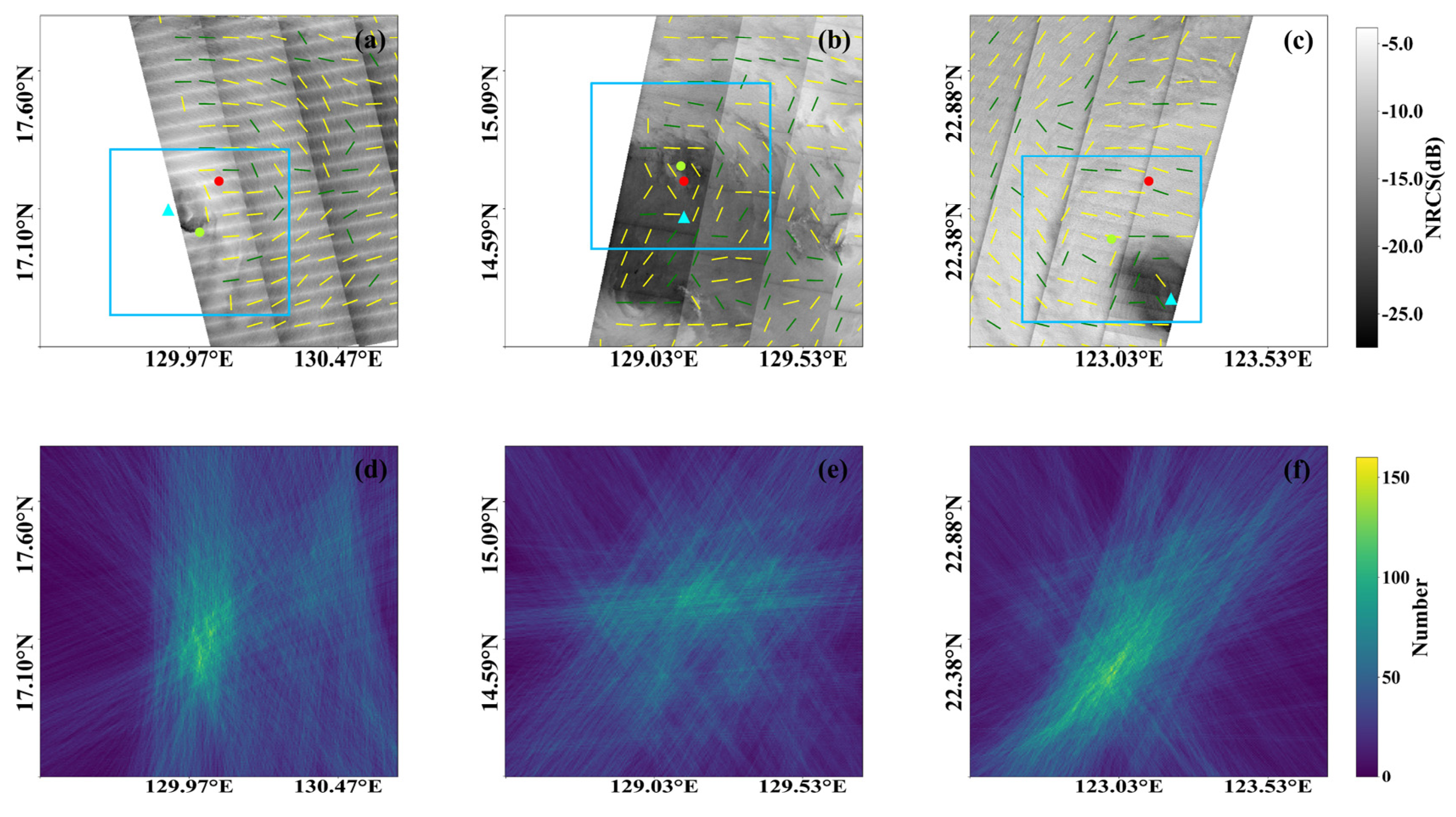
Figure 5a–c depict the precisely estimated center positions of TCs Noru, Doksuri, and Koinu, identified by green points. These green points represent the refined TC center positions after the algorithm has undergone its second stage of estimation, improving upon the initial coarse estimates. Figure 5d–f provide the heatmaps corresponding to the compensation angles of −0.5°, −27.5°, and −23.0° for TCs Noru, Doksuri, and Koinu, respectively. The location of the maximum value in each of these heatmaps represents the precisely estimated TC center position, also indicating the point where the algorithm’s refined calculations align closely with the actual center of the TC.
Figure 6 shows the results of the NRCS-adjusted TC center estimation. The position of the lowest NRCS value is the NRCS-adjusted TC center position. In this final stage of the estimation process, adjustments are made using the NRCS to further refine the accuracy of the TC center positions. The adjusted positions are represented by blue points. The NRCS adjustment involves fine-tuning the estimated positions by considering the radar backscatter characteristics of the sea surface.

5. Discussion

In this study, the accuracy of the TC center positions estimated by the automatic algorithm was assessed by comparing them with visually located TC center positions. This comparison is detailed in Table 2, where D1, D2, and D3 represent the distances between the visually located TC center positions and the coarsely estimated, precisely estimated, and NRCS-adjusted TC center positions, respectively. For TC Noru, the comparison yielded distances of 21.42 km for D1, 14.39 km for D2, and 8.19 km for D3. In the case of TC Doksuri, the distances were found to be 14.36 km for D1, 20.48 km for D2, and 17.10 km for D3. Interestingly, the initial coarse estimation (D1) provided a relatively accurate center position. However, the precision decreased slightly in the subsequent stages. For TC Koinu, the distances between the visually located and estimated positions were 47.82 km for D1, 31.59 km for D2, and 5.42 km for D3.
Upon analyzing the data presented in Table 2, an observable trend is that the estimation error for TC centers decreases as the estimation procedure progresses through its stages. These results illustrate a clear improvement in accuracy as the estimation process progresses. The initial coarse estimation provides a broad approximation, which is significantly refined during the precise estimation stage, and further honed by the NRCS adjustment, resulting in the accurate estimation. However, the case of TC Doksuri presents a notable exception to this general trend. Specifically, for Doksuri, the highest estimation accuracy was achieved during the first stage of the algorithm. This anomaly can be attributed to the distinct characteristics of TC Doksuri, particularly its larger eye region compared to TCs Noru and Koinu. The expansive size of Doksuri’s eye may have introduced complexities in Stage 2 and the optional stage, potentially complicating the TC-center estimation due to increased variability and structural details within the eye region itself.
In addition, the three SAR images used in this study, acquired in TOPSAR and ScanSAR modes, consist of multiple sub-swaths. While the splicing noise between sub-swaths and striping noise within sub-swaths could potentially interfere with SSWD retrieval, the algorithm demonstrated robust performance, with the TC-center estimation results maintaining high accuracy despite these challenges.

6. Conclusions

In this study, we aimed to assess the performance of miniaturized SAR images in automatic TC-center estimation and the robustness of a previously proposed automatic estimation algorithm. Specifically, three wide-swath miniaturized SAR images were utilized to estimate the centers of TCs Noru, Doksuri, and Koinu. The algorithm’s process is methodically divided into three stages: Stage 1 (coarse estimation), Stage 2 (precise estimation), and an optional stage (NRCS-adjusted estimation). To validate the accuracy of the estimated TC center positions, the algorithm’s outputs were compared with visually located data. For TC Noru, the accuracy improved from 21.42 km (Stage 1) and 14.39 km (Stage 2) to 8.19 km (optional stage). For TC Doksuri, the accuracy varied, with distances from 14.36 km (Stage 1) and 20.48 km (Stage 2) to 17.10 km (optional stage). For TC Koinu, the accuracy improved from 47.82 km (Stage 1) and 31.59 km (Stage 2) to 5.42 km (optional stage). These results underscore the potential of miniaturized SAR satellites in monitoring TCs.
However, a significant limitation of the algorithm is its dependence on the accuracy of wind direction retrieval. Inaccuracies in wind direction can lead to less precise TC-center estimations. Consequently, future research could focus on refining wind direction retrieval methods to enhance TC-center estimation accuracy. Additional studies will compare TC center positions derived from SAR images, satellite cloud images, and best-track data, examining discrepancies related to TC intensity, geographic regions, or other factors. Overall, the integration of miniaturized SAR technology into meteorological practices offers promising assistance in mitigating the effects of these powerful natural phenomena.

Author Contributions

Conceptualization, X.G. and S.S.; Methodology, Y.W. and H.F.; Datacuration, L.H., Z.H., Y.X. and G.W.; Writing—original draft, Y.W.; Writing—review & editing, X.G. and S.S.; Visualization, H.F. All authors have read and agreed to the published version of the manuscript.

Funding

This work was funded by the National Key Research and Development Project of China. (Grant 2017YFC1404800).

Institutional Review Board Statement

Not applicable.

Informed Consent Statement

Not applicable.

Data Availability Statement

The raw data utilized in this article will be made available by the authors on request.

Acknowledgments

The authors would like to thank the HiSea-1 C-band SAR satellite project and all collaborators, especially Fujian Satellite Date Development Company Ltd., and Fujian Hisea Digital Technology Company Ltd., for their cooperation in SAR applications.

Conflicts of Interest

The authors declare that they have no known competing financial interests or personal relationships that could have appeared to influence the work reported in this paper.

References

  1. Jaiswal, N.; Kishtawal, C.M. Objective detection of center of tropical cyclone in remotely sensed infrared images. IEEE J. Sel. Top. Appl. Earth Obs. Remote Sens. 2013, 6, 1031–1035. [Google Scholar] [CrossRef]
  2. Lu, X.; Yu, H.; Yang, X.; Li, X. Estimating tropical cyclone size in the Northwestern Pacific from geostationary satellite infrared images. Remote Sens. 2017, 9, 728. [Google Scholar] [CrossRef]
  3. Wimmers, A.J.; Velden, C.S. Advancements in objective multisatellite tropical cyclone center fixing. J. Appl. Meteorol. Climatol. 2016, 55, 197–212. [Google Scholar] [CrossRef]
  4. Zheng, G.; Liu, J.; Yang, J.; Li, X. Automatically Locate Tropical Cyclone Centers Using Top Cloud Motion Data Derived From Geostationary Satellite Images. IEEE Trans. Geosci. Remote Sens. 2019, 57, 10175–10190. [Google Scholar] [CrossRef]
  5. Yanyan, W.; Han, W.; Hong, C.; Wei-Chi, S. Tropical cyclone center location with digital image process. In Proceedings of the 2001 International Conferences on Info-Tech and Info-Net. Proceedings (Cat. No. 01EX479), Beijing, China, 29 October–1 November 2001; pp. 563–567. [Google Scholar]
  6. Wong, K.Y.; Yip, C.L.; Li, P.W. Automatic tropical cyclone eye fix using genetic algorithm. Expert Syst. Appl. 2008, 34, 643–656. [Google Scholar] [CrossRef]
  7. Wei, K.; Jing, Z.-l. Spiral band model optimization by chaos immune evolutionary algorithm for locating tropical cyclones. Atmos. Res. 2010, 97, 266–277. [Google Scholar] [CrossRef]
  8. Chaurasia, S.; Kishtawal, C.; Pal, P. An objective method of cyclone centre determination from geostationary satellite observations. Int. J. Remote Sens. 2010, 31, 2429–2440. [Google Scholar] [CrossRef]
  9. Piñeros, M.F.; Ritchie, E.A.; Tyo, J.S. Objective measures of tropical cyclone structure and intensity change from remotely sensed infrared image data. IEEE Trans. Geosci. Remote Sens. 2008, 46, 3574–3580. [Google Scholar] [CrossRef]
  10. Pao, T.-L.; Yeh, J.-H. Typhoon locating and reconstruction from the infrared satellite cloud image. J. Multimed. 2008, 3. [Google Scholar] [CrossRef]
  11. Elsner, J.B.; Kossin, J.P.; Jagger, T.H. The increasing intensity of the strongest tropical cyclones. Nature 2008, 455, 92–95. [Google Scholar] [CrossRef]
  12. Cheng, Y.-H.; Huang, S.-J.; Liu, A.K.; Ho, C.-R.; Kuo, N.-J. Observation of typhoon eyes on the sea surface using multi-sensors. Remote Sens. Environ. 2012, 123, 434–442. [Google Scholar] [CrossRef]
  13. Zhang, B.; Perrie, W. Recent progress on high wind-speed retrieval from multi-polarization SAR imagery: A review. Int. J. Remote Sens. 2014, 35, 4031–4045. [Google Scholar] [CrossRef]
  14. Jin, S.; Wang, S.; Li, X.; Jiao, L.; Zhang, J.A. Tropical Cyclone Center Location in SAR Images Based on Feature Learning and Visual Saliency. In Hurricane Monitoring with Spaceborne Synthetic Aperture Radar; Li, X., Ed.; Springer: Singapore, 2017; pp. 141–181. [Google Scholar]
  15. Zhou, X.; Yang, X.; Li, Z.; Yu, Y.; Bi, H.; Ma, S.; Li, X. Estimation of tropical cyclone parameters and wind fields from SAR images. Sci. China Earth Sci. 2013, 56, 1977–1987. [Google Scholar] [CrossRef]
  16. Combot, C.; Mouche, A.; Knaff, J.; Zhao, Y.; Zhao, Y.; Vinour, L.; Quilfen, Y.; Chapron, B. Extensive High-Resolution Synthetic Aperture Radar (SAR) Data Analysis of Tropical Cyclones: Comparisons with SFMR Flights and Best Track. Mon. Weather Rev. 2020, 148, 4545–4563. [Google Scholar] [CrossRef]
  17. Zhang, B.; Zhu, Z.; Perrie, W.; Tang, J.; Zhang, J.A. Estimating Tropical Cyclone Wind Structure and Intensity From Spaceborne Radiometer and Synthetic Aperture Radar. IEEE J. Sel. Top. Appl. Earth Obs. Remote Sens. 2021, 14, 4043–4050. [Google Scholar] [CrossRef]
  18. Xue, S.; Geng, X.; Meng, L.; Xie, T.; Huang, L.; Yan, X.-H. HISEA-1: The First C-Band SAR Miniaturized Satellite for Ocean and Coastal Observation. Remote Sens. 2021, 13, 2076. [Google Scholar] [CrossRef]
  19. Zheng, G.; Yang, J.; Liu, A.K.; Li, X.; Pichel, W.G.; He, S. Comparison of Typhoon Centers From SAR and IR Images and Those From Best Track Data Sets. IEEE Trans. Geosci. Remote Sens. 2016, 54, 1000–1012. [Google Scholar] [CrossRef]
  20. Jin, S.; Wang, S.; Li, X. Typhoon eye extraction with an automatic SAR image segmentation method. Int. J. Remote Sens. 2014, 35, 3978–3993. [Google Scholar] [CrossRef]
  21. Lee, I.K.; Shamsoddini, A.; Li, X.; Trinder, J.C.; Li, Z. Extracting hurricane eye morphology from spaceborne SAR images using morphological analysis. ISPRS J. Photogramm. Remote Sens. 2016, 117, 115–125. [Google Scholar] [CrossRef]
  22. Jin, S.; Li, X.; Yang, X.; Zhang, J.A.; Shen, D. Identification of Tropical Cyclone Centers in SAR Imagery Based on Template Matching and Particle Swarm Optimization Algorithms. IEEE Trans. Geosci. Remote Sens. 2019, 57, 598–608. [Google Scholar] [CrossRef]
  23. Wang, Y.; Zheng, G.; Li, X.; Zhou, L.; Liu, B.; Chen, P.; Ren, L.; Li, X. An Automatic Algorithm for Estimating Tropical Cyclone Centers in Synthetic Aperture Radar Imagery. IEEE Trans. Geosci. Remote Sens. 2021, 60, 1–16. [Google Scholar] [CrossRef]
  24. Mu, S.; Wang, H.; Li, X. A Deep Learning Model for Tropical Cyclone Center Localization Based on SAR Imagery. EGU Gen. Assem. 2024. [Google Scholar] [CrossRef]
  25. Wang, Y.; Li, Y.; Xie, Y.; Wei, G.; He, Z.; Geng, X.; Shang, S. Assessment of Sea-Surface Wind Retrieval from C-Band Miniaturized SAR Imagery. Sensors 2023, 23, 6313. [Google Scholar] [CrossRef] [PubMed]
  26. Sun, H.; Geng, X.; Meng, L.; Yan, X.-H. First Ocean Wave Retrieval from HISEA-1 SAR Imagery through an Improved Semi-Automatic Empirical Model. Remote Sens. 2023, 15, 3486. [Google Scholar] [CrossRef]
  27. Lv, S.; Meng, L.; Edwing, D.; Xue, S.; Geng, X.; Yan, X.-H. High-Performance Segmentation for Flood Mapping of HISEA-1 SAR Remote Sensing Images. Remote Sens. 2022, 14, 5504. [Google Scholar] [CrossRef]
  28. Xu, P.; Li, Q.; Zhang, B.; Wu, F.; Zhao, K.; Du, X.; Yang, C.; Zhong, R. On-Board Real-Time Ship Detection in HISEA-1 SAR Images Based on CFAR and Lightweight Deep Learning. Remote Sens. 2021, 13, 1995. [Google Scholar] [CrossRef]
  29. Zhang, J.A.; Uhlhorn, E.W. Hurricane sea surface inflow angle and an observation-based parametric model. Mon. Weather Rev. 2012, 140, 3587–3605. [Google Scholar] [CrossRef]
  30. Zhou, L.; Zheng, G.; Li, X.; Yang, J.; Ren, L.; Chen, P.; Zhang, H.; Lou, X. An Improved Local Gradient Method for Sea Surface Wind Direction Retrieval from SAR Imagery. Remote Sens. 2017, 9, 671. [Google Scholar] [CrossRef]
Figure 1. Flowchart of the TC-center estimation algorithm. β represents the compensation angle. The coarsely estimated center position is derived from Stage 1, the precisely estimated center position is derived from Stage 2, and NRCS-adjusted center position is derived from the optional stage.
Applsci 14 07047 g001
Figure 2. The rule for determining whether a line passes through a point. The green points represent a SSWD point. The green solid line depicts the retrieved SSWD, and the green dashed line represents the compensated SSWD, with β indicating the compensation angle. The black points represent candidate points, and the interval is M1 equal to the diameter of the circles. If the distance from a candidate point to a line is less than M1/2, the line is considered to pass through the candidate point. The red circles indicate that the line passes through their centered candidate points.
Applsci 14 07047 g002
Figure 3. Variation in maximum values in heatmaps by compensation angles. The vertical blue and orange lines represent the compensation angle corresponding to the peak values of the curves. (a) TC Noru; (b) TC Doksuri; (c) TC Koinu. The global maximum values of the first stage (Stage 1) occurred at 0.5°, −16.5°, and −17.5°, respectively, and the corresponding heat maps are shown in Figure 4; the global maximum values of the second stage (Stage 2) occurred at −0.5°, −27.5°, and −23.0°, respectively, and the corresponding heat maps are shown in Figure 5.
Applsci 14 07047 g003
Figure 4. Coarse estimation for centers of (a,d) TC Noru; (b,e) TC Doksuri; (c,f) TC Koinu. The coarsely estimated TC center positions are denoted by red points, while the visually located TC center positions are denoted by cyan triangles in (ac). The sub-SAR images inside the green boxes are used to precisely estimate the TC center position. (df) represent the heatmaps corresponding to the compensation angles of 0.5°, −16.5°, and −17.5°, respectively. The position of the maximum value in (df) represents the coarsely estimated TC center positions (red points in (ac)).
Applsci 14 07047 g004
Figure 5. Precise estimation for centers of (a,d) TC Noru; (b,d) TC Doksuri; (c,f) TC Koinu. The precisely estimated TC center positions are denoted by green points in (ac). The sub-SAR images inside the blue boxes are used to adjust the precise estimation by NRCS. (df) represent the heatmaps corresponding to the compensation angles of −0.5°, −27.5°, and −23.0°, respectively. The position of the maximum value in (df) represents the precisely estimated TC center positions (green points in (ac)).
Applsci 14 07047 g005
Figure 6. NRCS-adjusted estimation for centers of (a) TC Noru; (b) TC Doksuri; (c) TC Koinu. The NRCS-adjusted TC centers are denoted by blue points, with the point corresponding to the lowest NRCS value.
Applsci 14 07047 g006
Table 1. The information of TCs and corresponding SAR images.
NameClassification aUTC TimeSAR
Resolution (m)ModeOrbit DirectionLocation
NoruTropical Storm23 September 2022, 13:2310NS bAscendingPhilippine Sea
DoksuriTropical Storm23 July 2023, 01:3610TP cDescendingPhilippine Sea
KoinuSevere Typhoon04 October 2023, 02:4110NSDescendingPhilippine Sea
a The classification is derived from CMA. b NS represents Narrow ScanSAR mode. c TP represents TOPSAR mode.
Table 2. TC center positions estimated from SAR images and those from visually located data.
NameClassificationVisually Located
Lon
(°E)
Lat
(°N)
D1 (km)D2 (km)D3 (km)
NoruTropical Storm129.9017.1021.4214.398.19
DoksuriTropical Storm129.1314.5614.3620.4817.10
KoinuSevere Typhoon123.2022.0547.8231.595.42
Disclaimer/Publisher’s Note: The statements, opinions and data contained in all publications are solely those of the individual author(s) and contributor(s) and not of MDPI and/or the editor(s). MDPI and/or the editor(s) disclaim responsibility for any injury to people or property resulting from any ideas, methods, instructions or products referred to in the content.