Article

Study on Multi-Span Tension Coupling Relationship of Gravure Printed Electronic Equipment

1
School of Mechatronics Engineering, Henan University of Science and Technology, Luoyang 471000, China
2
High-End Bearing Collaborative Innovation Center of Henan Province, Luoyang 471000, China
*
Author to whom correspondence should be addressed.
Appl. Sci. 2024, 14(16), 7054; https://doi.org/10.3390/app14167054 (registering DOI)
Submission received: 19 June 2024 / Revised: 30 July 2024 / Accepted: 9 August 2024 / Published: 12 August 2024

Abstract

:
To improve the performance of the tension control system in gravure printed electronic equipment, it is necessary to study the tension system model of gravure-printing electronic equipment. This paper focuses on the coupling characteristics of multi-span tension systems. Firstly, based on the single-span tension model, the mathematical model of the printing tension subsystem is established and simplified into a general multi-span tension coupling model. Then, using the relationship between the inputs and outputs of the system, the coupling model is simulated using MATLAB/Simulink and verified through experiments on the gravure printed electronic platform. Finally, the coupling relationship and influence laws among multi-physical quantities of the system are analyzed. The research results show that changes in the input web tension of the multi-span system will affect the steady-state tension values of all subsequent spans. Moreover, the speed change in a roller in the multi-span system will not only affect the steady-state tension value of its own span, but also cause transient tension fluctuations in all subsequent spans. The findings of this paper provide an important theoretical basis for the research of the tension system in gravure printed electronic equipment, contributing to the enhancement of printed electronic product quality.

1. Introduction

Roll-to-roll (R2R) gravure printed technology has become the best choice for the large-scale and continuous production of printed electronics owing to its characteristics of continuous production, thick ink layer, and stable process. Currently, there are increasing numbers of studies on gravure-printed electronic products and processes. Shakeel introduced digital twin technology into the R2R system for thin-film transistor (TFT) manufacturing [1]. Shan has developed a R2R gravure-printing system for producing electric heaters on polymeric substrates [2]. Lee studied the R2R gravure-printing process of silver nanoparticle ink [3]. Gong studied the R2R gravure-printing process of flexible planar heterojunction perovskite solar cells [4].
Gravure-printed electronic equipment is a crucial piece of equipment suitable for the mass continuous production of printed electronic products. The tension system is one of the most important systems in gravure printed electronic equipment, used to generate tension on the web and meet the printing process requirements. The tension system of gravure printed electronic equipment can be divided into three tension subsystems based on their functions: unwinding, printing, and rewinding. Each subsystem has different requirements for tension, and the web is used as a link between the subsystems to form a unified whole, as shown in Figure 1. The tension system has a complex structure, changeable working conditions, and many influencing factors, displaying characteristics of non-linearity, strong coupling, and strong interference.
Compared to traditional image and text gravure printed equipment, printing electronics have higher requirements for tension systems, such as smaller tension fluctuations and stronger anti-interference capabilities. In order to improve the accuracy of tension control, an accurate mathematical model that can reflect the multivariable coupling relationships must be established. Additionally, the multi-span coupling relationships within the tension system must be thoroughly analyzed and studied.
There are many studies on the tension system of gravure printed equipment, and these research works mainly focus on two parts: model and control, with more research on control methods and algorithms. Some researchers have combined PID control algorithm with other control algorithms to devise a synthetic control method for tension control. Park designed a variable gain PID to control the tension of the unwinding system [5]. Raul adopted a second-order PI control to achieve the comprehensive control of tension and speed in the tension system and designed a feedforward control strategy to improve control accuracy for known disturbances in the system [6,7].
Recently, advanced control methods such as robust control, fuzzy control, and neural network control have also been studied and applied to tension systems. Gassmann adopted the H∞ robust control algorithm in the tension control of the winding system, which has a good interference suppression effect in the simulation results [8]. Eum achieved robust control of the unwinding tension subsystem by designing a disturbance observer [9]. Ponniah proposed an adaptive fuzzy control algorithm for tension systems, which can automatically adjust control parameters to adapt to changes in system parameters and structural uncertainties [10]. Choi used multi-layer neural networks to achieve the semi-decoupling control of speed and tension [11]. Tran designed a backstepping control strategy for a tension control system, and simulation showed that it can achieve high tension control accuracy [12]. Wang proposed a decoupling controller based on active disturbance rejection control to address the tension control problem of the rewinding tension system in gravure printed machines, achieving a high-precision control of the rewinding tension system [13]. He studied the application of active disturbance rejection control technology in rewinding tension [14]. He designed a high-precision reduced-order observer-based LQR control method for roll-to-roll systems [15]. Kim introduced an advanced observer-based single-loop feedback system for roll-to-roll machine tension control applications, and the simulation results numerically validated the feasibility of the proposed solution [16].
The relevant studies on tension models are as follows. The mechanism of tension generation is the foundation of tension systems, but only a few researchers have studied the tension mechanism. Jeon and Dwivedula analyzed the mechanism of tension generation between two rollers [17,18]. Ma conducted a dynamic study on the film and guide rollers in the film transport system of gravure printing [19,20]. He analyzed the mechanism of tension generation in detail, established a mathematical model for a single span, and further studied the influence mechanism of the drying system on tension in printed electronic equipment [21,22]. Jeong developed a tension model for flexible electronics that enables accurate and precise tension control [23]. Wang also considered the influence of temperature in system modeling [24].
The unwinding and rewinding tension systems of electronic-shaft gravure printed equipment are hot topics in tension research. Shao studied the model of the winding tension subsystem and established mathematical models for components in the rewinding tension subsystem, such as the winding mechanism and swing roller mechanism [25]. Kang and Gassmann conducted modeling analysis on the commonly used swing roller mechanism in tension systems [8,26]. Zhou studied the characteristics of the discontinuous unwinding tension subsystem and established a model of the discontinuous unwinding tension subsystem [27].
It can be seen that the above studies mainly focus on the unwinding tension subsystem or rewinding tension subsystem, while research on the printing tension subsystem is relatively scarce. In these studies, there is almost no research on the tension coupling relationship. In printed electronic equipment, higher requirements are placed on the tension system for product accuracy; therefore, it is necessary to conduct more in-depth research on the factors that affect tension, such as the coupling relationship in multi-span tension systems.
The tension system of gravure printed electronic equipment is a multi-span system composed of multiple functional units connected by the web. A multi-span tension system is not simply a combination of multiple single-span tension systems; rather, there is a coupling relationship between each single-span tension system. To obtain the characteristics of the multi-span tension system, it is necessary to study the multi-span tension coupling model.
Based on the research on single-span tension systems, this article conducts in-depth research on the coupling relationship of multi-span tension systems. Firstly, according to the specific structural characteristics of the printing tension subsystem, the mathematical model of the printing tension subsystem including drying factors is established, and then aiming at the multi-input and multi-output physical quantities of the system, through simulation and experiment methods, the multi-physical quantity coupling law of multi-span tension system is analyzed and verified.

2. Multi-Span Tension Model

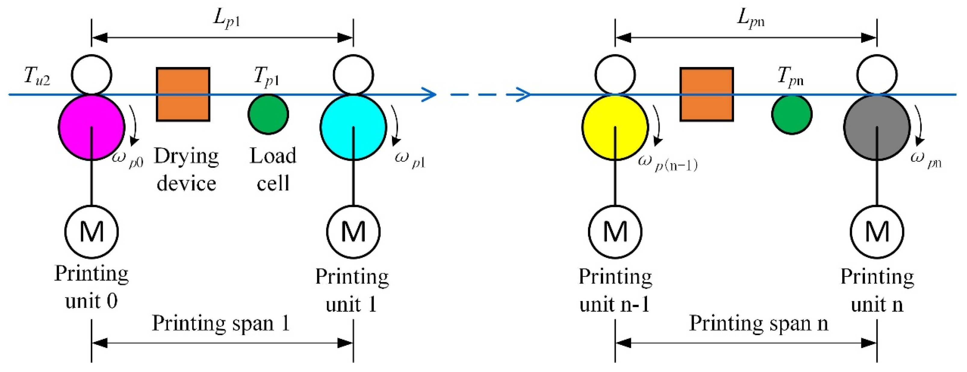
The multi-span web transmission system is composed of multiple single-span web transmission units connected in series, which is the most common form of web transmission system. In gravure printed electronic equipment, the printing tension subsystem is located between the unwinding tension subsystem and the rewinding tension subsystem. Its input is the output of the unwinding tension subsystem, and its output is the input of the rewinding tension subsystem. In the printing section, the tension system is coupled with the registration system, and the former is the foundation of the latter. The tension system of the printing section is mainly composed of several printing units sequentially arranged, and the adjacent printing units constitute a printing span, as shown in Figure 2. Therefore, the tension system of the printing section is essentially a typical multi-span web tension system, but a drying device is installed in each printing span.
In the gravure printed electronic equipment, due to the absence of additional registration adjustment mechanisms, the web length of each printing span remains unchanged. Therefore, based on the single-span web tension model in reference [21], combined with the relationship between the drying system and web tension, the multi-span tension system model for the printing section can be established:
{ [ L p 1 + L D p 1 ( E E E D 1 ) ] d T p 1 ( t ) d t = [ A E E T p 1 ( t ) ] R p 1 ω p 1 ( t ) [ A E E T u 2 ( t ) ] R p 0 ω p 0 ( t ) [ L p 2 + L D p 2 ( E E E D 1 ) ] d T p 2 ( t ) d t = [ A E E T p 2 ( t ) ] R p 2 ω p 2 ( t ) [ A E E T p 1 ( t ) ] R p 1 ω p 1 ( t ) [ L p n + L D p n ( E E E D 1 ) ] d T p n ( t ) d t = [ A E E T p n ( t ) ] R p n ω p n ( t ) [ A E E T p ( n - 1 ) ( t ) ] R p ( n - 1 ) ω p ( n - 1 ) ( t )
The descriptions of the parameters in Equation (1) are shown in Table 1.
Equation (1) represents a multi-span tension coupling system for gravure printing, where each printing span is represented by an equation, and adjacent printing spans are coupled together by the roller speed of the shared printing unit in the middle.
In order to study the coupling characteristics of the multi-span tension system and facilitate the analysis and experimental verification, the printing tension system in Figure 2 is simplified by omitting the drying device, and the multi-span web transmission model shown in Figure 3 is obtained. Figure 3 shows the basic model of multi-span web transmission, which is composed of three spans, and a set of roller systems is shared between the two adjacent spans.
According to Equation (1), the tension model of the multi-span system in Figure 3 can be obtained.
{ L 2 d T 2 ( t ) d t = [ A E T 2 ( t ) ] R 2 ω 2 ( t ) [ A E T 1 ( t ) ] R 1 ω 1 ( t ) L 3 d T 3 ( t ) d t = [ A E T 3 ( t ) ] R 3 ω 3 ( t ) [ A E T 2 ( t ) ] R 2 ω 2 ( t ) L 4 d T 4 ( t ) d t = [ A E T 4 ( t ) ] R 4 ω 4 ( t ) [ A E T 3 ( t ) ] R 3 ω 3 ( t )
In the multi-span tension system, the input variables are roller speeds ω 1 , ω 2 , ω 3 , ω 4 , and web tension T 1 , and the output variables are T 2 , T 3 , and T 4 . From the mathematical model of the multi-span tension system, it can be seen that there is a coupling relationship between the adjacent spans, and there is also a coupling relationship between the input and output within a single span. It is a non-linear coupled system with multiple inputs and outputs.

3. Experimental Equipment

In order to analyze the coupling characteristics of the multi-span tension system, the simulation and experimental verification of the multi-span tension system are carried out. The simulation is conducted on MATLAB/Simulink, and the experimental verification is completed on a dedicated experimental platform.
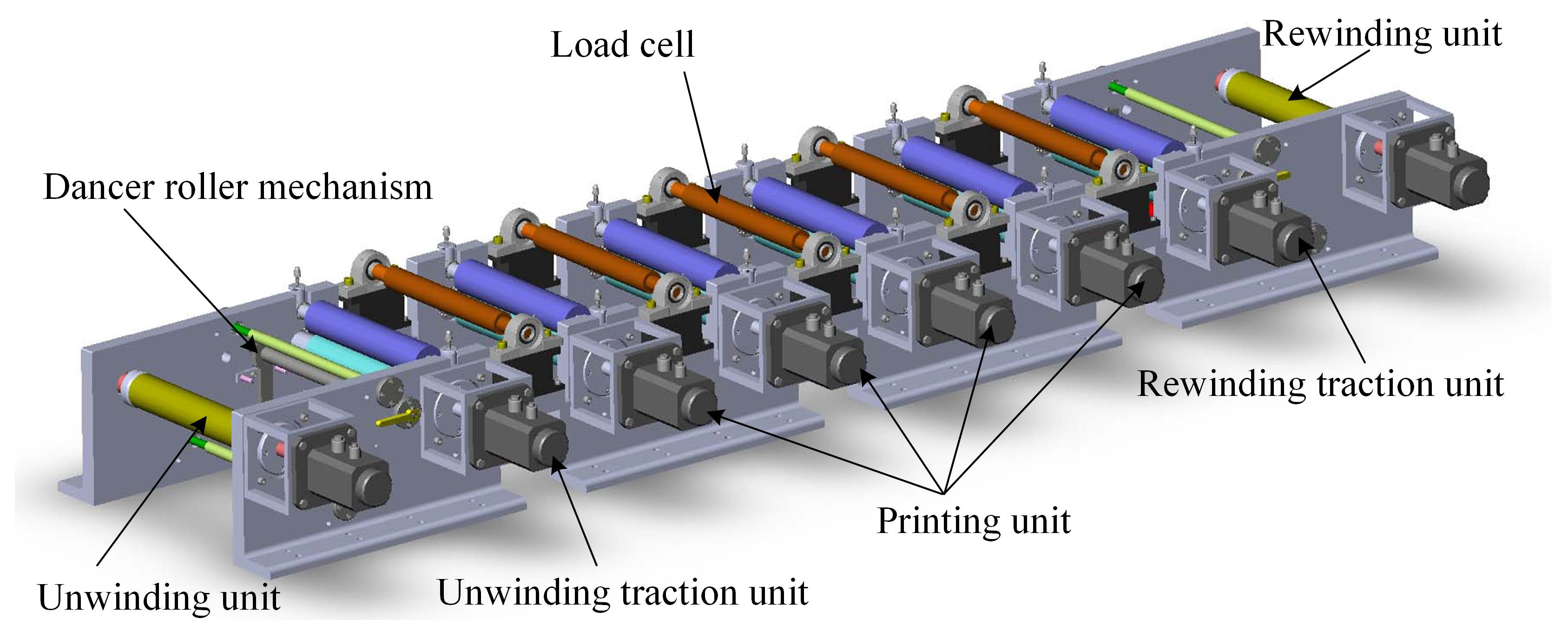
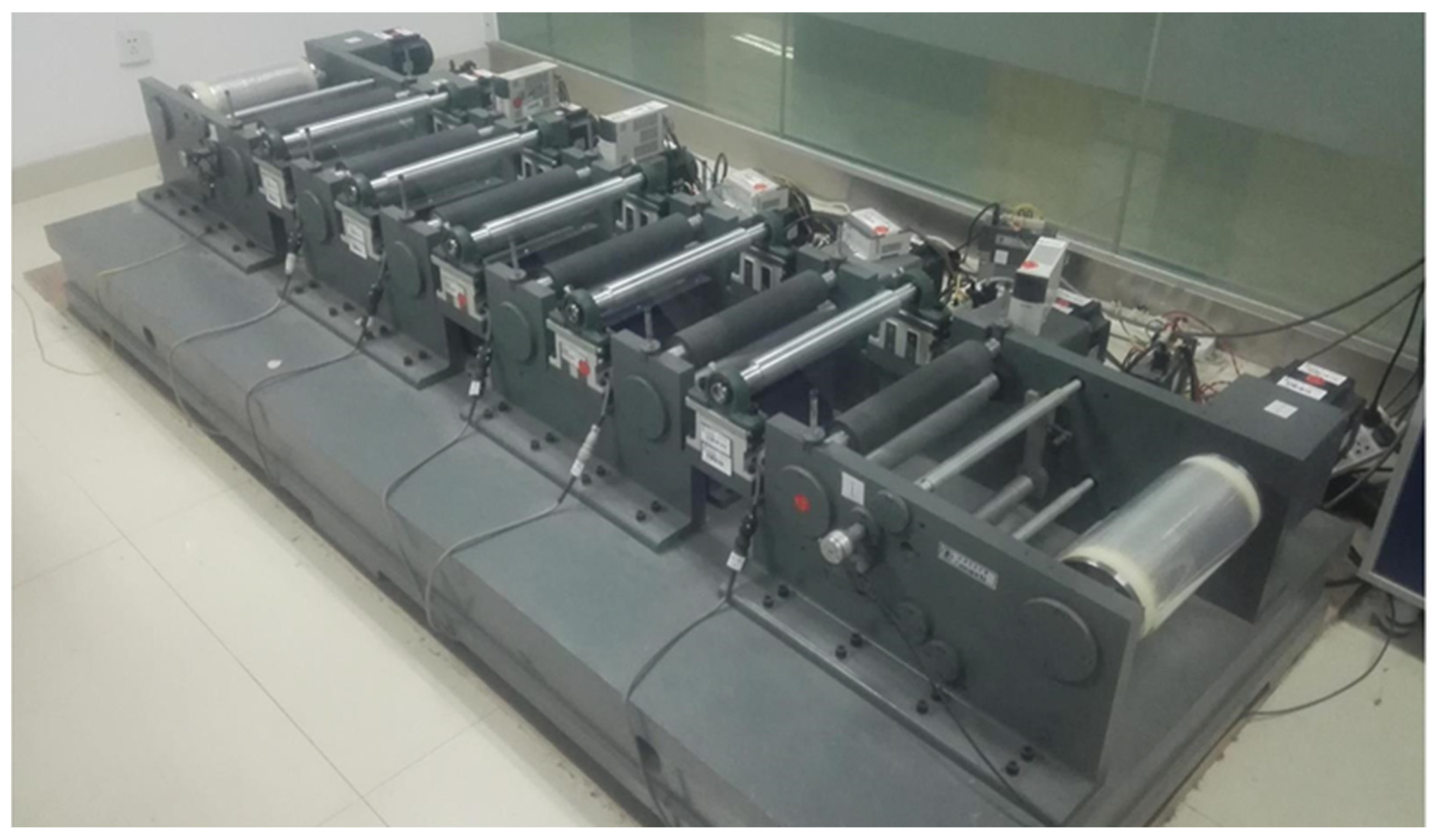
Figure 4 and Figure 5 show the three-dimensional model and physical photograph of the gravure printed electronic experiment platform, which is composed of an unwinding unit, an unwinding traction unit, four printing units, a rewinding traction unit, a rewinding unit, two dancer roller mechanisms, five load cells, etc.
The electrical system of the experimental platform adopts the centralized control structure of an industrial computer + motion controller, which is mainly divided into three parts according to their functions: industrial computer, motion control, and signal acquisition and processing. The electrical system structure is shown in Figure 6.
The main technical indicators of the experimental platform are shown in Table 2.

4. Coupling Relation Analysis

The coupling relationship of the multi-span tension system is studied according to the inputs T 1 , ω 1 , ω 2 , ω 3 , and ω 4 . The steady-state value of the system is as follows: the input web tension is 50 N, and the rotation speed of each roller is 100 r/min. The following text analyzes the system step response generated by five types of inputs.

4.1. Varying Web Tension T 1

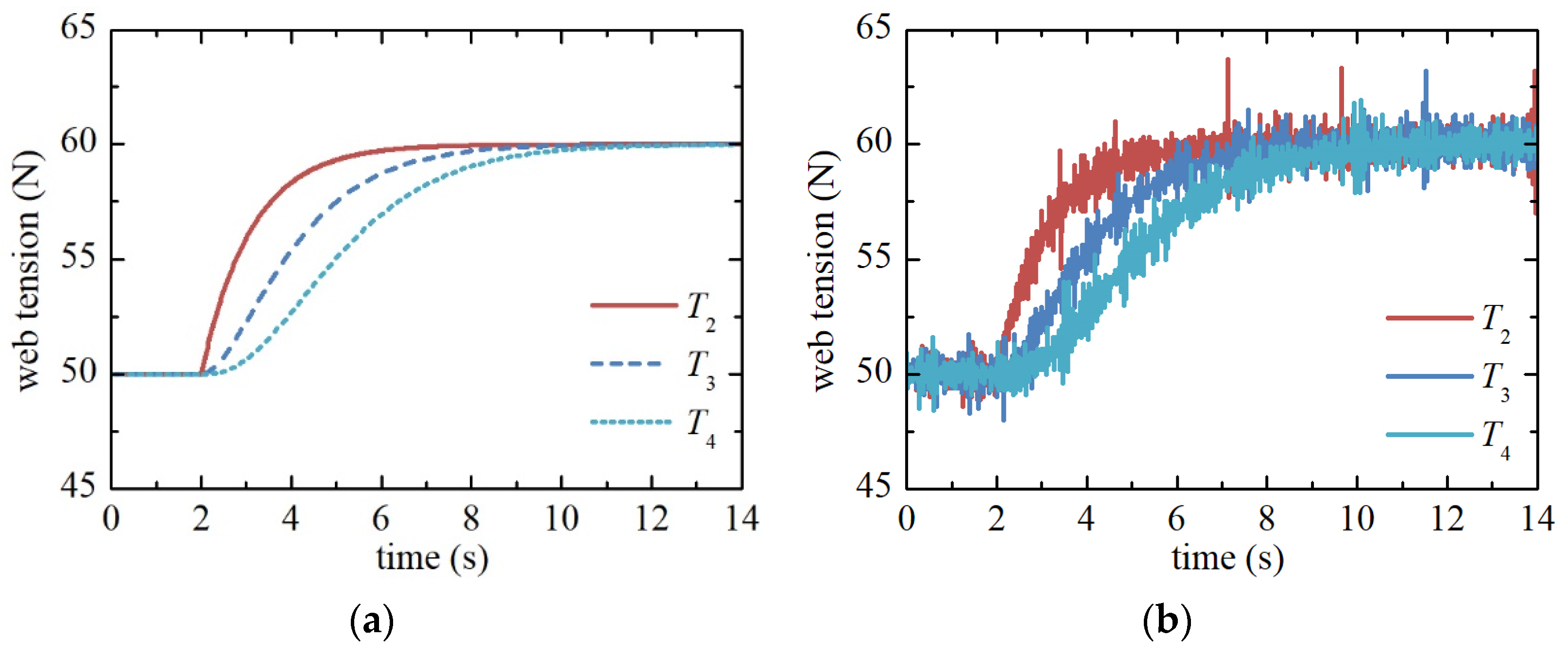
In this case, web tension T 1 is the input, T 2 , T 3 , and T 4 are the outputs, and ω 1 , ω 2 , ω 3 , and ω 4 are constants. When the system is running stably, T 1 generates a 10 N step increment, and the step responses of T 2 , T 3 , and T 4 are shown in Figure 7.
The items in Equation (2) are all first-order differential equations. It is obvious that for a step input, the step response of a single-span system changes monotonously and tends to be stable, and Figure 7 shows the same results. For the transient response in Figure 7a, the settling times of T 2 , T 3 , and T 4 are 4.36 s, 6.50 s, and 8.38 s, respectively, indicating that the web tension settling times for each span increase sequentially. This is because for spans located later, the path through which tension is transmitted is longer and the time consumption is also longer. For the steady-state response in Figure 7a, the steady-state value increments of T 2 , T 3 , and T 4 are all 10 N, which is equal to T 1 , which means that the change in input web tension will be equally transmitted to the web tension of each span. The experimental results in Figure 7b are consistent with the simulation results, which verify the correctness of the model and the phenomenon of equal transmission of steady-state tension values when the input is the web tension T 1 .

4.2. Varying Rotational Speed ω 1

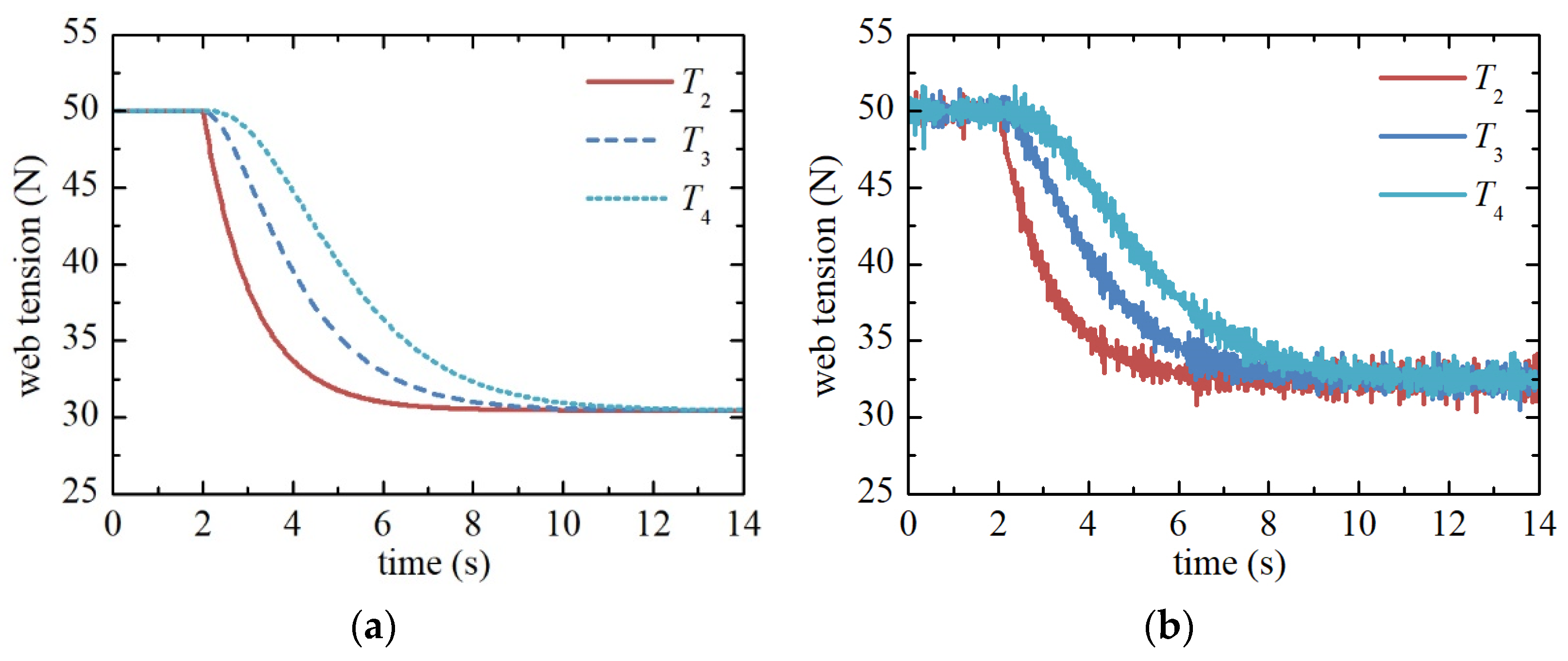
Rotational speed ω 1 is the input, T 2 , T 3 , and T 4 are the outputs, and T 1 , ω 2 , ω 3 , and ω 4 are constants. When the system is running stably, ω 1 generates a step increment of 0.04 r/min, and the step responses of T 2 , T 3 , and T 4 are shown in Figure 8.
In Figure 8a, for the transient response, the settling times of T 2 , T 3 , and T 4 are 4.36 s, 6.50 s and 8.38 s, respectively, that is, the tension settling time of each span increases sequentially, which is the same as when the input is T 1 . For the steady-state response in Figure 8a, the decrements of the steady-state values of T 2 , T 3 , and T 4 are all 19.54 N, that is, the equal decrements of the steady-state value of tension caused by the speed increment of roller 1 will be transferred to each span. The experimental results of Figure 8b are consistent with the simulation results, which verify the correctness of the model and the equivalent transfer of the steady-state value of tension when the input is ω 1 .

4.3. Varying Rotational Speed ω 2

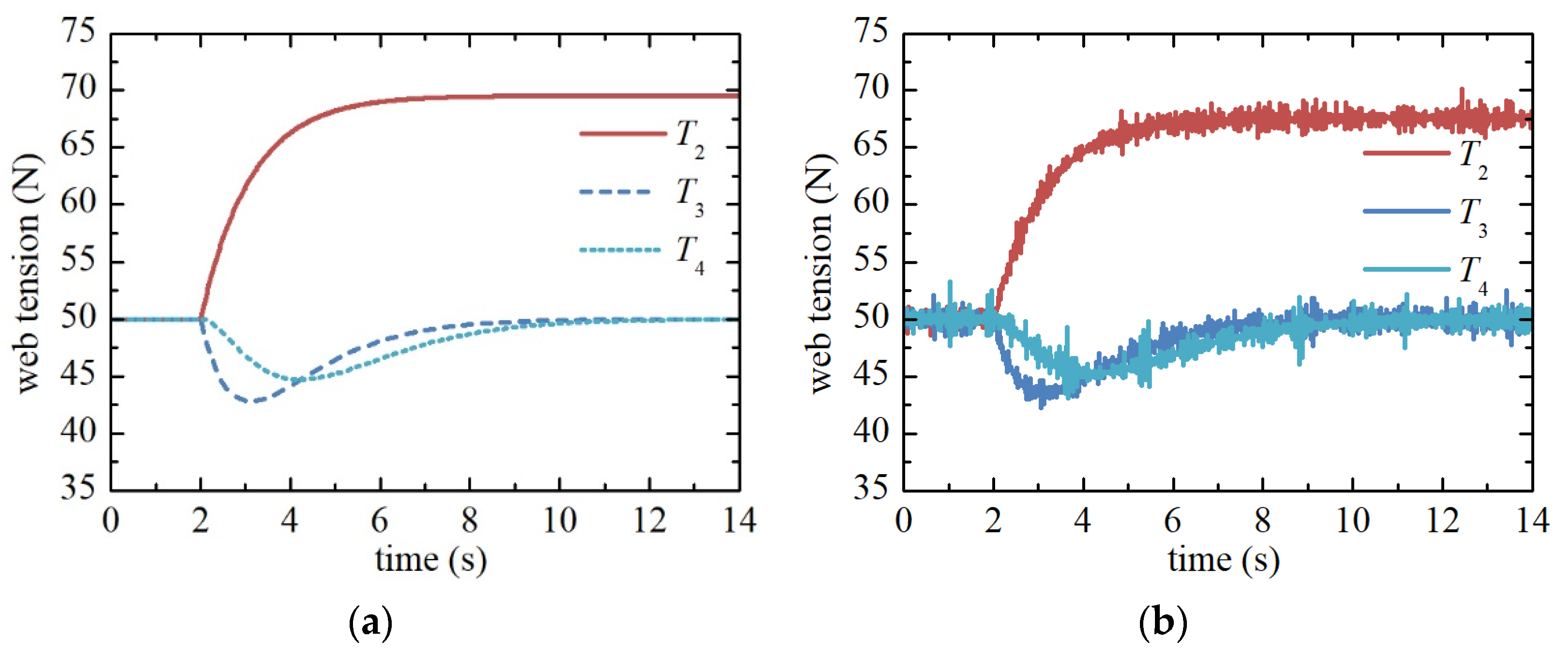
Rotational speed ω 2 is the input, T 2 , T 3 , and T 4 are the outputs, and T 1 , ω 1 , ω 3 , and ω 4 are constants. When the system is running stably, ω 2 generates a 0.04 r/min step increment, and the step responses of T 2 , T 3 , and T 4 are shown in Figure 9.
In Figure 9a, for span 2, the step increment of ω 2 causes a step change in tension T 2 , and its step response is consistent with the law described above, that is, the increase in discharge roller speed will lead to the increase in web tension in this span.
For span 3, T 3 first decreases and then returns to its original steady-state value after reaching its negative peak. The reasons for this phenomenon are as follows: roller 2 is the feed roller of span 3, and the increase in ω 2 will cause a negative step change of T 3 . Meanwhile, T 2 is the input of span 3, and the T 2 step increase caused by the increase of ω 2 is transferred to span 3, which compensates for the decrease in T 3 and finally returns T 3 to the initial steady state. ω 2 causes a T 2 change, which is then propagated to the web of span 3. This is an indirect process that lags behind the direct change in T 3 caused by the ω 2 change, so T 3 will first rapidly decrease and then slowly increase.
For span 4, the roller speeds at both ends remain constant, while T 3 experiences tension fluctuations that decrease first and then increase. This tension fluctuation will be transmitted to span 4, causing T 4 to experience fluctuations that decrease first and then increase. However, the amplitude of this tension fluctuation is smaller, and the arrival time of the peak value is delayed.
In addition, it can be seen from Figure 9a that when the input is ω 2 , for the transient response, the settling times of T 2 , T 3 , and T 4 are 4.36 s, 6.50 s, and 8.38 s, respectively, which is the same as the previous input of T 1 and ω 1 , indicating that the settling time progressively increases. For the steady-state response, the change of ω 1 only affects the steady-state value of T 2 , without affecting the steady-state tensions in other spans.
The experimental results in Figure 9b verify the correctness of the tension model when the input is the velocity of roller 2, and they also confirm the phenomenon of backward transmission of tension fluctuations.

4.4. Varying Rotational Speed ω 3

Rotational speed ω 3 is the input, T 2 , T 3 , and T 4 are the outputs, and T 1 , ω 1 , ω 2 , and ω 4 are constants. When the system is running stably, ω 3 generates a 0.04 r/min step increment, and the step responses of T 2 , T 3 , and T 4 are shown in Figure 10.
In Figure 10a, the step increment of ω 3 results in a step change in T 3 and a negative fluctuation in T 4 , with the observed results resembling those in Figure 9a. However, T 2 remains unchanged, indicating that variations in ω 3 do not affect T 2 . The experimental results presented in Figure 10 are largely consistent with the simulation results, thereby validating the correctness of the model.

4.5. Varying Rotational Speed ω 4

Rotational speed ω 4 is the input, T 2 , T 3 , and T 4 are the outputs, and T 1 , ω 1 , ω 2 , and ω 3 are constants. When the system is running stably, ω 4 generates a 0.04 r/min step increment, and the step responses of T 2 , T 3 , and T 4 are shown in Figure 11.
In Figure 11a, the step increment of ω 4 causes T 4 to undergo a step change, whereas T 2 and T 3 remain unchanged, indicating that variations in ω 4 do not affect T 2 and T 3 . The experimental results in Figure 11b are largely consistent with the simulation results, which verifies the correctness of the model.

5. Conclusions

In order to improve the product accuracy of gravure printed electronic equipment, the tension system needs to be thoroughly studied. In this paper, based on the single-span tension model, a general multi-span tension system model is established, which is a typical multi-input and multi-output coupling model. Through the step response simulation and experiment of each input, it is found that the change in the input web tension of the multi-span system will produce an equivalent change in all subsequent spans, and the settling time will increase in turn. Moreover, the speed change in a roller in the multi-span system will have an impact on the steady-state value of the web tension in the current span, and will not have any noticeable effect on the web tension of each span before the current span. The speed change will also generate a tension fluctuation in each span behind the roller, the amplitude of tension fluctuation will decrease gradually along the direction of web transmission, and the peak time of wave motion will be delayed in turn. This paper reveals the law of mutual coupling between multi-input and multi-output in a multi-span tension system, and the research results provide a theoretical basis for tension system design. In the subsequent tension control stage, the coupling relationship must be decoupled to improve the precision of tension control.

Author Contributions

Conceptualization, K.H. and J.L.; methodology, K.H.; data curation, P.H. and S.L.; writing—original draft, K.H. and X.W.; writing—review and editing, J.L. and X.W.; funding acquisition, K.H. and J.L. All authors have read and agreed to the published version of the manuscript.

Funding

This research was supported by the National Key R&D Program of China grant number 2023YFB4605105 and the Key Research Projects of Henan Province grant number 222102220044.

Institutional Review Board Statement

Not applicable.

Informed Consent Statement

Not applicable.

Data Availability Statement

The data presented in this study are available in the article.

Conflicts of Interest

The authors declare no conflicts of interest.

References

  1. Shakeel, A.; Maskey, B.; Shrestha, Y. Towards Digital Twin Implementation in Roll-To-Roll Gravure Printed Electronics: Overlay Printing Registration Error Prediction Based on Printing Process Parameters. Nanomaterials 2023, 13, 1008. [Google Scholar] [CrossRef] [PubMed]
  2. Shan, X.C.; Sunappan, V.; Salam, B.; Lok, B.K. Roll-to-Roll Gravure Printing of Electric Heaters on Polymeric Substrates. In Proceedings of the 2020 IEEE 22nd Electronics Packaging Technology Conference (EPTC), Singapore, 2–4 December 2020; pp. 201–204. [Google Scholar]
  3. Gong, C.; Tong, S.; Huang, K.; Li, H.; Huang, H.; Zhang, J.; Yang, J. Characterization of Silver Nanoparticle Inks toward Stable Roll-to-Roll Gravure Printing. Flex. Print. Electron. 2022, 7, 014003. [Google Scholar]
  4. Gong, C.; Tong, S.; Huang, K.; Li, H.; Huang, H.; Zhang, J.; Yang, J. Flexible Planar Heterojunction Perovskite Solar Cells Fabricated via Sequential Roll-to-Roll Microgravure Printing and Slot-Die Coating Deposition. Sol. RRL 2019, 4, 1900204. [Google Scholar] [CrossRef]
  5. Park, J.C.; Jeon, S.W.; Nam, K.S.; Liu, L.; Sun, J.; Kim, C.H. Tension Control of Web of Winder Span Using Adaptive Gain Control Method. Jpn. J. Appl. Phys. 2014, 53, 05HC11. [Google Scholar] [CrossRef]
  6. Raul, P.R.; Manyam, S.G.; Pagilla, P.R.; Darbha, S. Output Regulation of Nonlinear Systems with Application to Roll-to-Roll Manufacturing Systems. IEEE/ASME Trans. Mechatron. 2015, 20, 1089–1098. [Google Scholar] [CrossRef]
  7. Raul, P.; Pagilla, P. Design and Implementation of Adaptive PI Control Schemes for Web Tension Control in Roll-to-Roll (R2R) Manufacturing. Isa Trans 2015, 56, 276–287. [Google Scholar] [CrossRef] [PubMed]
  8. Gassmann, V.; Knittel, D.; Pagilla, P.R.; Bueno, M.A. Fixed-Order H∞ Tension Control in the Unwinding Section of a Web Handling System Using a Pendulum Dancer. IEEE Trans. Control Syst. Technol. 2011, 20, 173–180. [Google Scholar] [CrossRef]
  9. Eum, S.; Lee, J.; Nam, K. Robust Tension Control of Roll-to-Roll Winding Equipment Based on a Disturbance Observer. In Proceedings of the IECON 2016-42nd Annual Conference of the IEEE Industrial Electronics Society, Florence, Italy, 23–26 October 2016; pp. 625–630. [Google Scholar]
  10. Ponniah, G.; Zubair, M.; Doh, Y.H.; Choi, K.H. Fuzzy Decoupling to Reduce Propagation of Tension Disturbances in Roll-to-Roll System. Int. J. Adv. Manuf. Technol. 2014, 71, 153–163. [Google Scholar] [CrossRef]
  11. Choi, K.; Zubair, M.; Ponniah, G. Web Tension Control of Multispan Roll-to-Roll System by Artificial Neural Networks for Printed Electronics. Proc. Inst. Mech. Eng. Part C J. Mech. Eng. Sci. 2013, 227, 2361–2376. [Google Scholar] [CrossRef]
  12. Tran, T.; Choi, K. A Backstepping-Based Control Algorithm for Multi-Span Roll-to-Roll Web System. Int. J. Adv. Manuf. Technol. 2014, 70, 45–61. [Google Scholar] [CrossRef]
  13. Wang, Z.; Liu, S.; He, K.; Shi, W.; Chen, S. Design Decoupling Controller for Rewinding System of the Gravure Printing Machines. In Proceedings of the 2020 IEEE 5th Information Technology and Mechatronics Engineering Conference (ITOEC), Chongqing, China, 12–14 June 2020; pp. 908–912. [Google Scholar]
  14. He, K.; Liu, S.; Shi, W.; Wang, Z. Decoupling Control for Rewinding Tension System of the Roll-to-Roll Printing Equipment. Packag. Eng. 2020, 41, 209–216. [Google Scholar]
  15. He, Z.; Chen, Z.; Huang, X.; Ma, D. A Reduced-Order Observer-Based LQR Control Method for Roll-to-Roll Systems. J. Control Eng. Appl. Inform. 2023, 25, 12–20. [Google Scholar]
  16. Kim, S.; Kim, D.; Ahn, C. Observer-Based Critically Damped Feedback Systems for Nonlinear Roll-to-Roll Printing Machine Applications Under Decentralized Strategy. Int. J. Robust Nonlinear Control 2024, 34, 4343–4362. [Google Scholar] [CrossRef]
  17. Jeon, S.; Kim, C.; Kim, C. Fast Stabilization of Web Tension in Drying Process of Roll-to-Roll Printing Equipment for Printed Electronics. J. Mech. Sci. Technol. 2015, 29, 5069–5074. [Google Scholar] [CrossRef]
  18. Dwivedula, R.; Pagilla, P. Effect of Backlash on Web Tension in Roll-to-Roll Manufacturing Systems: Mathematical Model, Mitigation Method and Experimental Evaluation. In Proceedings of the 2013 IEEE International Conference on Control Applications (CCA), Hyderabad, India, 28–30 August 2013; pp. 1087–1092. [Google Scholar]
  19. Ma, L.E.; Mei, X.S.; Li, Y.F. Mechanical Behaviors of Guide Roller in Web Transfer System. J. Xi’an Jiaotong Univ. 2014, 48, 86–91. [Google Scholar]
  20. Ma, L.; Kong, F.; Cheng, G.; Sun, J.; Wu, J.; Liu, S. The Influence of Web Moving Speed on Flow Field Characteristics of the Entrained Air. Packag. Eng. 2017, 38, 21–24. [Google Scholar]
  21. He, K.; Liu, S.; Wang, K.; Mei, X. Thermal Characteristics of Plastic Film Tension in Roll-to-Roll Gravure Printed Electronics. Appl. Sci. 2018, 8, 312. [Google Scholar] [CrossRef]
  22. He, K.; Liu, S.; Wang, K.; Mei, X. Effect of Environment Temperature on Web Tension in Shaft-Less Drive Gravure Printing System. Adv. Mech. Eng. 2019, 11, 1–10. [Google Scholar] [CrossRef]
  23. Jeong, J.; Gafurov, A.N.; Park, P.; Kim, I.; Kim, H.C.; Kang, D.; Oh, D.; Lee, T.M. Tension Modeling and Precise Tension Control of Roll-to-Roll System for Flexible Electronics. Flex. Print. Electron. 2021, 6, 1–13. [Google Scholar] [CrossRef]
  24. Wang, M.; Yang, J.; Zhang, X.; Pan, Y. Analytical Modeling of Temperature Field and Thermal Error of Spindle System of Precision Boring Machine. J. Inn. Mong. Univ. Technol. (Nat. Sci. Ed.) 2023, 42, 445–453. [Google Scholar]
  25. Shao, M.Y.; Wu, J.M.; Wang, Y.; Fang, K.; Guo, X.X. Research on Modeling Method of Winding Tension System for Gravure Printing Machine. In Proceedings of the 2016 Symposium on Piezoelectricity, Acoustic Waves, and Device Applications (SPAWDA), Xi’an, China, 21–24 October 2016; pp. 110–114. [Google Scholar]
  26. Kang, H.K.; Lee, C.W.; Shin, K.H.; Kim, S.C. Modeling and Matching Design of a Tension Controller Using Pendulum Dancer in Roll-to-Roll Systems. In Proceedings of the 2010 IEEE Industry Applications Society Annual Meeting, Houston, TX, USA, 3–7 October 2010; pp. 1–8. [Google Scholar]
  27. Zhou, C.; Chen, J.; Yin, Z. Modeling, Simulation and Experiment of Tension Control in Film Non-Continuous Unwinding System. Electr. Autom. 2013, 35, 9–11. [Google Scholar]
Figure 1. Diagram of a roll-to-roll gravure printed electronic machine.
Applsci 14 07054 g001
Figure 2. Schematic diagram of web transmission in the tension system of the printing section.
Applsci 14 07054 g002
Figure 3. Schematic diagram of multi-span web transmission.
Applsci 14 07054 g003
Figure 4. Three-dimensional model of the gravure printed electronic experimental platform.
Applsci 14 07054 g004
Figure 5. Physical photograph of the gravure printed electronic experimental platform.
Applsci 14 07054 g005
Figure 6. Electrical system structure diagram of the experimental platform.
Applsci 14 07054 g006
Figure 7. Step responses of web tension T 2 , T 3 , and T 4 when T 1 has a 10 N step increment: (a) simulation; (b) experiment.
Applsci 14 07054 g007
Figure 8. Step responses of web tension T 2 , T 3 , and T 4 when the speed ω 1 has a 0.04 r/min step increment: (a) simulation; (b) experiment.
Applsci 14 07054 g008
Figure 9. Step responses of web tension T 2 , T 3 , and T 4 when the speed ω 2 has a 0.04 r/min step increment: (a) simulation; (b) experiment.
Applsci 14 07054 g009
Figure 10. Step responses of web tension T 2 , T 3 , and T 4 when the speed ω 3 has a 0.04 r/min step increment: (a) simulation; (b) experiment.
Applsci 14 07054 g010
Figure 11. Step responses of web tension T 2 , T 3 , and T 4 when the speed ω 4 has a 0.04 r/min step increment: (a) simulation; (b) experiment.
Applsci 14 07054 g011
Table 1. Parameter description.
ParameterDescription
L p i Web length in the i-th span
L D p i Web length inside the i-th drying device
T p i Web tension in the i-th span
ω p i The angular velocity of the i-th printing roller
R p i The radius of the i-th printing roller
E E Young’s modulus at ambient temperature
E D Young’s modulus at drying temperature
A The cross-sectional area of the web
Table 2. Main technical indicators of the experimental platform.
ParameterValueUnit
Groups of printing unit4group
Maximum web width300mm
Printing roller diameter60mm
Tension range10~150N
Maximum unwinding and rewinding Diameter350mm
Web materialPET/
Web length in a span350mm
Cross-section area of web10mm2
Young’s modulus of PET(25 °C)4.89 × 10⁹Pa
Disclaimer/Publisher’s Note: The statements, opinions and data contained in all publications are solely those of the individual author(s) and contributor(s) and not of MDPI and/or the editor(s). MDPI and/or the editor(s) disclaim responsibility for any injury to people or property resulting from any ideas, methods, instructions or products referred to in the content.