Article

Modeling of Coupled Structural Electromagnetic Statistical Concept for Examining Performance Sensitivity of Antenna Array to Distortion at Millimeter-Wave

by
Oluwole John Famoriji
* and
Thokozani Shongwe
Department of Electrical and Electronic Engineering Technology, University of Johannesburg, P.O. Box 524, Auckland Park, Johannesburg 2006, South Africa
*
Author to whom correspondence should be addressed.
Appl. Sci. 2024, 14(16), 7111; https://doi.org/10.3390/app14167111
Submission received: 11 July 2024 / Revised: 9 August 2024 / Accepted: 12 August 2024 / Published: 13 August 2024

Abstract

:
Millimeter-wave (mmWave) antenna arrays are pivotal components in modern wireless communication systems, offering high data rates and improved spectrum efficiency. However, the performance of mmWave antenna arrays can be significantly affected by structural distortions, such as mechanical deformations and environmental conditions, which may lead to deviations in beamforming characteristics and radiation patterns. In this paper, we present a comprehensive sensitivity study of mmWave antenna arrays to structural distortion, employing a coupled structural–electromagnetic statistical concept. The proposed model integrates structural analysis techniques with electromagnetic simulations to assess the impact of structural distortions on the performance of mmWave antenna arrays. In addition, the model incorporates random element positioning, making it easy to analyze radiation pattern sensitivity to structural deformation. Demonstrating the applicability of the model, a 10 × 10 microstrip patch antenna array is designed to assess the performance of the model with a random position error and saddle shape distortion. The results of the model are then compared against the acceptable results from the HFSS software (version 13.0), where a good agreement is observed between the two results. The results show the gain variation and sidelobe level under various degrees of distortion and random errors, respectively. These results provide a guide for design, deployment, and optimization of mmWave communication networks in real-world environments. In addition, the model provides valuable insights into the trade-offs between antenna performance, structural integrity, and system reliability, paving the way for more efficient and dependable mmWave communication systems in the era of 5G and beyond.

1. Introduction

Millimeter-wave (mmWave) communication systems have emerged as a key technology for meeting the ever-increasing demand for high-speed wireless connectivity in the era of 5G and beyond. Operating at frequencies above 30 GHz, mmWave systems offer abundant spectrum resources and the potential for multi-gigabit data rates, promising revolutionary advancements in wireless communication networks. Central to the success of mmWave technology are antenna arrays, which enable beamforming, spatial multiplexing, and enhanced spectral efficiency. However, the performance of mmWave antenna arrays can be significantly influenced by structural distortions, such as mechanical deformations and environmental conditions, which may alter the antenna’s radiation characteristics and beamforming capabilities. Traditional design approaches often neglect the coupled effects of structural dynamics and electromagnetic behavior, leading to suboptimal performance and reliability issues in practical deployments [1,2,3,4]. In [3], the influence of environmental factors is investigated, such as temperature variations and wind-induced vibrations, on the performance of mmWave antenna arrays. The findings revealed that thermal expansion and mechanical vibrations can lead to deviations in beam steering and the degradation of antenna gain, underscoring the need for robust antenna designs capable of withstanding environmental uncertainties. Therefore, there is a critical need for comprehensive sensitivity studies to assess the impact of structural distortion on the performance of mmWave antenna arrays.
Antenna arrays with high detection and tracking capacity are multifunctional, highly reliable, and have been employed in different applications [1,2,3]. With the development of technological advancements, there is a high demand for correct and accurate design mechanisms and array optimization. The beamwidth, gain, sidelobe, and boresight pointing accuracy of the antenna are the determinants of the performances of array antennas [3]. Also, random errors emanated from fabrication/manufacturing, assembling procedure, and structural/mechanical deformation are caused by vibration, impact force, and high thermal power, which results in the displacement of elements and consequently affects the performance of the antenna, such as higher sidelobe level, gain loss, inaccurate boresight pointing, and beamwidth broadening [4,5,6,7]. The effect is more serious at a higher frequency of operation and will be more in the implementation process of future 5G technology (i.e., at mmWave). The analysis of the requirements for next-generation wireless communication systems to meet future applications highlights the need for higher transmission speeds and very low latency as critical aspects. While precise standards are yet to be established, the ambitious goals identified for 5G and beyond wireless systems include the following: fast data transfer rates; aiming for 1 TB per second download speed; wide bandwidth availability; improved coverage; almost zero latency (approximately 0.1 ms); increased overall data traffic and number of connected users; reduced energy consumption; and the capability of connecting intelligence rather than just objects through the use of Artificial Intelligence [8,9].
The combination of systematic distortion and random position error causes random element positioning which results in degraded electromagnetic performance of the array [10,11,12,13,14]. It causes shortened communication distance and low resistance to interference, which severely limits high performance actualization of antenna arrays. Hence, structural errors or deformation limits the realization of desired antenna array performance. So, deeply exploring the relationship between structural error and EM performance of antenna arrays in the presence of random element positioning is necessary [15,16].
There are some previous studies that concentrate on the impact of mechanical distortion and random position error on array performance. When analyzing the associated error of element random positioning, it is generally assumed that the impacts of an element’s position errors show on the impact of amplitude and phase excitation errors. Hence, excitation with both phase and amplitude errors have a normal distribution profile, and the relationship that exists between variances and single electrical variables, like sidelobe level, was derived by employing a statistical approach [16,17,18,19,20]. But the impacts of random position error as a type of structural error cannot be quantified easily by phase and amplitude tolerances. Reference [14] introduced a statistical approach for quantifying the uncertainties in structural parameters and material properties affecting the performance of mmWave antenna arrays. The study utilized probabilistic methods to assess the sensitivity of antenna gain, beamwidth, and sidelobe levels to variations in structural integrity, providing valuable insights for robust antenna design and optimization.
Reference [21] worked on symmetrical and asymmetrical bends’ influence on antenna array performance. The impacts of antenna array plane distortions, which include potato chip, sag, Bessel, and sinusoidal profile, are presented in [22] (see Figure 1). However, [21,22] took systematic error into consideration without accounting for the random position errors which are inevitable in fabrication and operation processes. Furthermore, some works were also tailored towards influences of random error, such as [23], which evaluated how active phased array (hexagonal) performance is impacted by random error (s), and they made useful guides available. However, systematic distortion was not considered in this work. References [24,25] show that the influence of random error is the same as the effect of excitation current error (s), and random current errors (s) on antenna performance were critically looked into, but no direct relationship was given between random error and performance of the antenna.
Furthermore, reference [26] estimated position error (s) in subarrays and its effect on array behavior employing theoretical statistical probability. In this method, many repeated computations are needed to determine antenna statistical performance. Refs. [27,28] present a linear relationship between systematic distortion and random error to evaluate their influence of array behavioral patterns. Conversely, in a practical sense, the numbers of systematic errors and random errors show a large variation; therefore, linear relationships mitigate random error impacts whenever there is a large variation between the two errors. Also, random error is stochastic in nature while systematic error is deterministic; the combined errors lead to random performance of electromagnetics. Therefore, whenever random error exists, it is better to determine the performance of EM from a statistical approach. This paper, therefore, proposes a method that employs array random positioning for an effective statistical performance assessment of the antenna array. Therefore, based on electromechanical coupling, a coupled structural–EM statistical model is proposed, and the model is verified using Ansoft HFSS model-based results. By considering the coupled effects of structural dynamics and electromagnetic behavior, we can develop more resilient and dependable mmWave antenna arrays capable of operating effectively in diverse conditions. Ultimately, this research contributes to the advancement of mmWave technology, enabling the realization of high-speed, reliable, and efficient wireless communication systems for a wide range of applications.

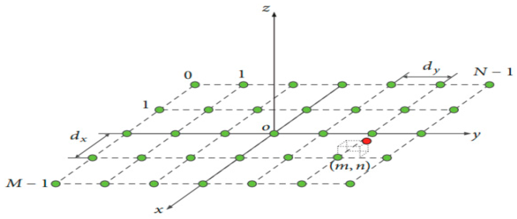
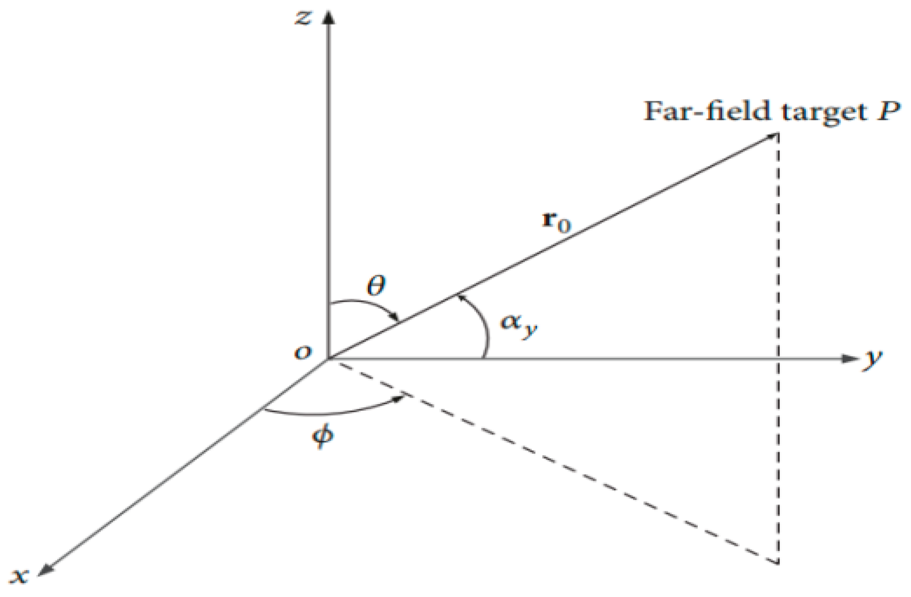
2. Proposed Coupled Structure–Electromagnetic Statistical Model

Figure 2 shows the configuration of antenna array elements whose numbers are M × N, with equal spacing. dy and dx are the distances between the radiators in both x and y directions. (θ, ϕ ) is the pointing far-field direction based on the Oxyz coordinate in Figure 3 with cosine direction as (cos αx, cos αy, cos αz) [29].
Antenna fabrication and operating process result in structure errors, which include systematic distortion and random error. Assuming that the radiator (m, n), (0 ≤ mM − 1, 0 ≤ nN − 1) has a random error of ( Δ x m n r , Δ y m n r , Δ z m n r ), phase difference Δ Φ m n r with respect to Figure 1’s coordinate origin is expressed as
Δ Φ m n r = k ( Δ x m n r s i n θ c o s ϕ + Δ y m n r s i n θ s i n ϕ + Δ z m n r c o s θ )
Also, by assumption that the radiator (m, n) systematic distortion is given as ( Δ x m n s , Δ y m n s , Δ z m n s ), then the phase difference Δ Φ m n s with respect to Figure 1’s coordinate origin is given as
Δ Φ m n s = k ( Δ x m n s s i n θ c o s ϕ + Δ y m n s s i n θ s i n ϕ + Δ z m n s c o s θ )
Based on the antenna array superposition principle without coupling, the planar rectangular active antenna array field pattern density function with random position error and systematic distortion is presented as
E s r ( θ , ϕ ) = f e ( θ , ϕ ) m = 0 M 1 n = 0 N 1 I m n e j ( Φ m n + Δ Φ m n r + Δ Φ m n s + φ m n B
where fe(θ, ϕ ) represents the free space pattern function of the element, Imn represents the amplitude excitation current of the element (m, n), φ m n B is the inherent phase difference in the array decided by the phase shifter, and Φ m n = kmdx sin θ cos ϕ + kndy sin θ sin  ϕ denotes the initial spatial phase distribution. Practically, the element random position error (s) is probabilistic in nature; it then becomes important to statistically evaluate the characteristic of EM for antenna array, including random error. Let random position errors in x, y, and z directions be Δ x m n r , Δ y m n r , and Δ z m n r subjected to normal distribution, with zero means and σ x 2 , σ y 2 , and σ z 2 variances, respectively. Hence, the random phase difference Δ Φ m n r in Equation (1) is a normal distribution function, and the variance is expressed as
E s r ( θ , ϕ ) σ Φ r 2 = k 2 σ x 2 s i n θ c o s ϕ 2 + σ y 2 s i n θ s i n ϕ 2 + σ z 2 c o s ϕ 2
For all random parameters that are normally distributed as x ~ N (0, σx), the associated relationship c o s   x ¯ and s i n   x ¯ is presented in reference [30,31,32,33,34]. Employing the average of exponential function, e j x = e σ 2   x / 2 , the average field density pattern function Esr (θ, ϕ ) in Equation (3) is expressed as
E s r ( θ , ϕ ) ¯ = f e ( θ , ϕ ) m = 0 M 1 n = 0 N 1 I m n e j ( Φ m n + Δ Φ m n s + φ m n B ) e Δ Φ m n r ¯ = E s ( θ , ϕ ) e ( 1 2 ) σ Φ r 2
Es (θ, ϕ ) represents the field density of the pattern function together with the associated systematic distortion. The antenna array mean power pattern function is derived based on variance property σ E s r 2 = E s r   ( θ ,   ϕ ) E s r * ( θ ,   ϕ )   ¯ E s r ( θ ,   ϕ ) E s r * ( θ ,   ϕ ) ¯ as
P s r ( θ , ϕ ) ¯ = E s r   ( θ ,   ϕ ) E s r * ( θ ,   ϕ )   ¯ = σ E s r 2 + E s r ( θ ,   ϕ ) E s r * ( θ ,   ϕ ) ¯
Putting E s r ( θ ,   ϕ ) function into Equation (6), the pattern function mean power is given as
σ E s r 2 defines the variance of Esr (θ, ϕ ), and its equation can be deduced. According to [24], Esr (θ, ϕ ) can be expressed in real and imaginary parts. Let X = m = 0 M 1 m = 0 N 1 X m n and Y = m = 0 M 1 m = 0 N 1 Y m n represent the real and imaginary parts, respectively. The variance σ E s r 2 is estimated as
σ E s r 2 = σ X 2 + σ Y 2 = m = 0 M 1 n = 0 N 1 σ X m n 2 + m = 0 M 1 n = 0 N 1 σ Y m n 2
where σ X m n 2 = X m n 2 ¯ X m n ¯ 2 and σ Y m n 2 = Y m n 2 ¯ Y m n ¯ 2 . The variance σ X m n 2 is given as follows:
σ X m n 2 = f e ( θ ,   ϕ ) 2 I m n 2 ( 1 + cos 2 Δ Φ m n + 2 Δ Φ m n s + 2 φ m n B e 2 σ Φ r 2 2 1 + cos 2 Δ Φ m n + 2 Δ Φ m n s + 2 φ m n B 2 e σ Φ r 2 )
Y m n ¯ = f e ( θ ,   ϕ ) I m n s i n ( 2 Δ Φ m n + 2 Δ Φ m n s + 2 φ m n B ) e ( 1 2 ) σ Φ r 2
Y m n 2 ¯ = f e θ ,   ϕ 2 I m n 2 1 c o s ( 2 Δ Φ m n + 2 Δ Φ m n s + 2 φ m n B ) e 2 σ Φ r 2 2
σ Y m n 2 = f e θ ,   ϕ 2 I m n 2 ( 1 cos 2 Δ Φ m n + 2 Δ Φ m n s + 2 φ m n B e 2 σ Φ r 2 2 1 cos 2 Δ Φ m n + 2 Δ Φ m n s + 2 φ m n B e σ Φ r 2 2 )
Substituting Equations (8) and (11) into Equation (7), σ E s r 2 then results in
σ E s r 2 = m = 0 M 1 n = 0 N 1 σ X m n 2 + m = 0 M 1 n = 0 N 1 σ Y m n 2 = f e θ ,   ϕ 2 ( 1 e σ Φ r 2 ) m = 0 M 1 n = 0 N 1 I m n 2
The proposed coupled structure–electromagnetic statistic model, which is the mean power pattern function with associated element position randomness, is stated as
P s r ( θ , ϕ ) ¯ = E s θ ,   ϕ 2 e k 2 [ σ x 2 s i n θ c o s ϕ 2 + σ y 2 s i n θ s i n ϕ 2 + σ z 2 c o s θ 2 ] + f e θ ,   ϕ 2 { ( 1 e k 2 ) E s θ ,   ϕ 2 e k 2 [ σ x 2 s i n θ c o s ϕ 2 + σ y 2 s i n θ s i n ϕ 2 + σ z 2 c o s θ 2 ] } . m = 0 M 1 n = 0 N 1 I m n 2

3. Coupled Structure–Electromagnetic Statistical Model Validation

Ansoft HFSS software version 13.0 has been tested and trusted. It provides accurate electromagnetic solutions and is used for reliable and efficient antenna designs. Therefore, it is appropriate to validate the correctness of the coupled structure–EM statistic model via comparison with the widely used HFSS software simulations. To illustrate the validity, a 10 × 10 microstrip patch antenna array, which operates at millimeter-wave frequency, is designed and simulated. It has the same intervals of 0.75λ along x and y directions as presented in Figure 4. Each patch element has a length L = 4.953 mm and width W = 4.160 mm, and the total array size is 60 mm by 60 mm.
The amplitude and phase of the initial excitation current are equal. Initiating structure error random samples, a saddle-shaped distortion is introduced with minimum displacement λ/6 in the z direction as systematic distortion. It is equally assumed that the random position errors along the x, y, and z planes satisfy normal distribution with λ/30 variance and 0 mean. The performance of the array with the associated error sample of the structure is separately simulated using HFSS software with no coupling effect. The average performance of the array is computed by finding average total performances estimated from the total samples of error due to structure. One thousand (1000) samples (structure error) were considered because there is no further change in the results when the mean of the array performance is more than 1000 samples. The computed performance of the proposed model is compared with the result generated from HFSS. The parameters are listed in Table 1, and the compared results are as depicted in Figure 5.
The coupled structure model and HFSS-based results agree well, and they exhibit consistency in the main lobe and side lobe areas. The boresight pointing, beamwidth, and gain are all the same in both planes. This implies that the coupled structured model and HFSS-based results have the same main lobe areas (Figure 5). The first sidelobe shows some differences in the absolute figures of 0 dB and 0.09 dB in ϕ = 0° and ϕ = 90° planes, correspondingly. On the other hand, for the second, third, fourth, and fifth sidelobes, the peak variations in absolute figures are 0.43 dB and 0.48 dB in ϕ = 0° and ϕ = 90° planes, respectively. The above results obtained demonstrate the effectiveness and efficiency of the proposed model in the analysis of the element position randomness effect on the electromagnetic radiation performance of the antenna array. Therefore, the proposed model can quickly and effectively evaluate the performance of the antenna, which consequently provides array structural design and optimization guidelines.

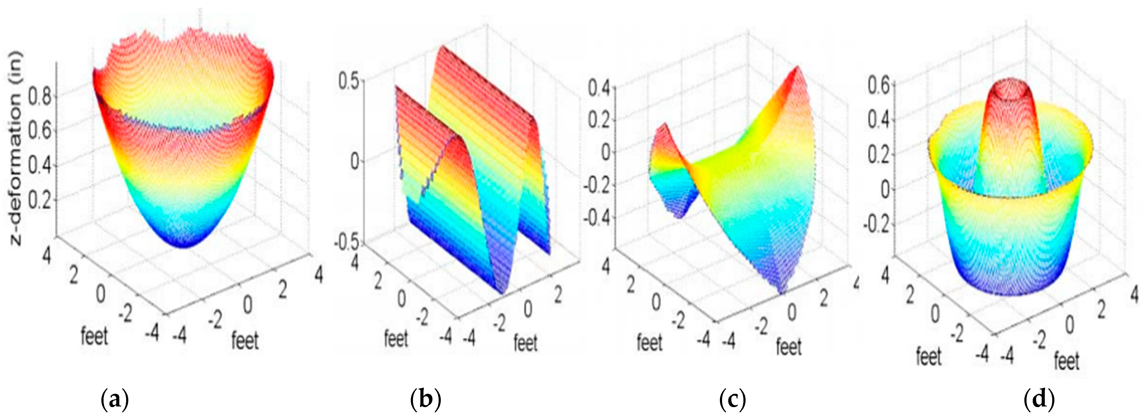
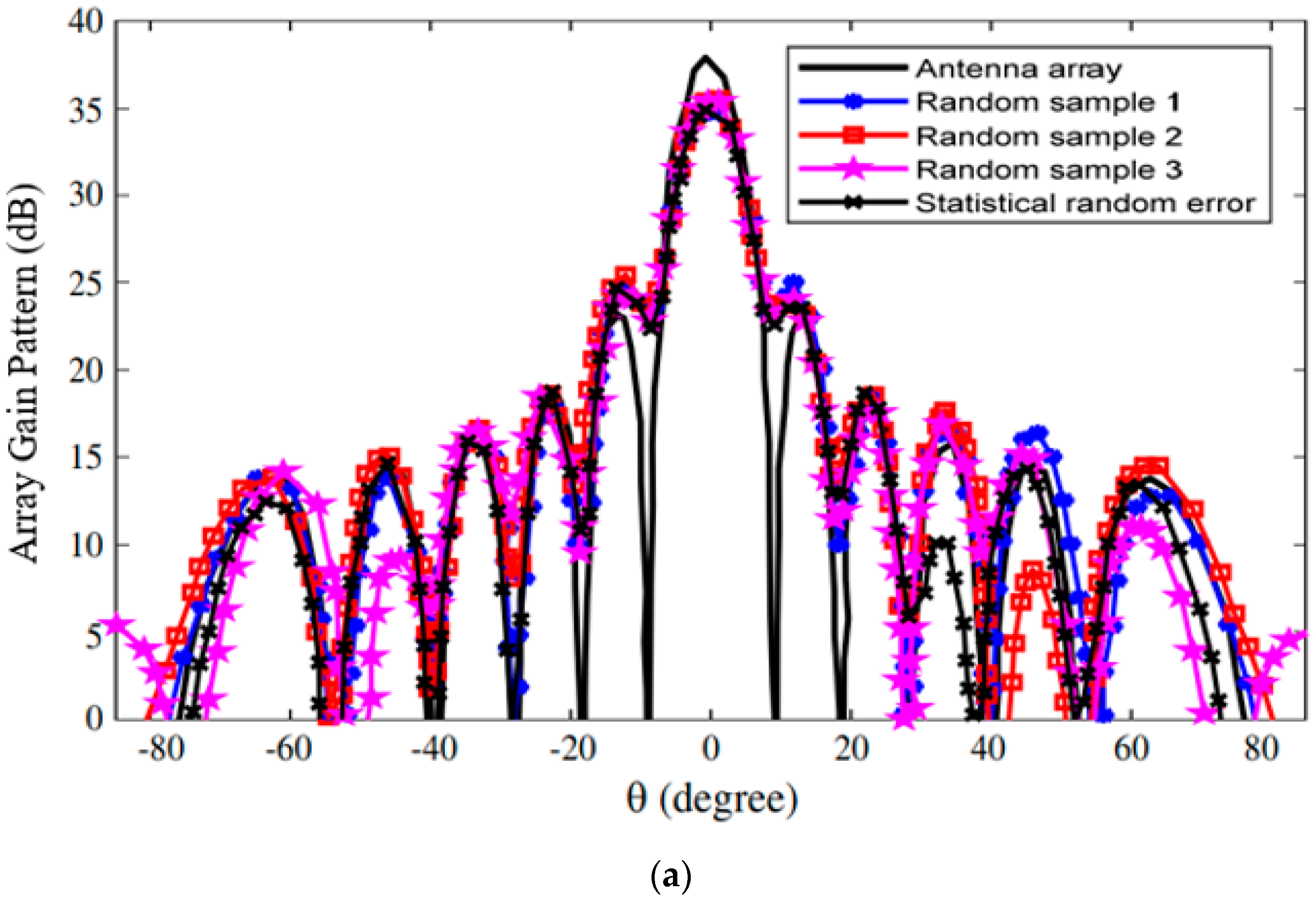
4. Simulation Example and Analysis

The structural deformation of the antenna array in practice usually causes an error due to random element positioning and systematic deformation. The randomness in the element positioning error is quantified as a random variable. Also, the distortion exhibited in practice is generally saddle-shaped. According to the surface mathematical properties, the phase center of a saddle-shaped element in position (m, n) is expressed as
Δ Z m n = Δ Z m a x x m n 2 x m a x 2 y m n 2 y m a x 2
where ΔZmax is the maximum displacement of antenna array elements (systematic error) in z coordinate, and ymax and xmax are the array aperture width and half-length, respectively. In this section, antenna array with both element random position error and saddle shape distortion is addressed. Consider a rectangular 10 × 10 microstrip patch array operating at 28.9 GHz frequency (Figure 6). The element spacing along x and y coordinates is λ/2. Random error (s) in the x, y, and z coordinates is (are) assumed normal distribution of zero average and λ/20 variance. λ/5 is selected as the saddle-shaped maximum displacement in the z plane. Rogers R5880 substrate is used. It has a relative permittivity of 2.2, thickness height of 0.254 mm, and tangential loss tan δ of 0.001. We used the corporate feeding method for the antenna. The corporate feeding technique is most popular in microstrip antenna, and its corporate feeding system is flexible. The systematic distortion is considered saddle-shaped, while three random samples (random samples 1–3) are emulated based on similar normal distribution. The antenna gain used is Psr (θ, ϕ ) = Esr (θ, ϕ ) E s r * (θ, ϕ ), where Esr (θ, ϕ ) is the field intensity in Equation (3). The proposed statistical model is then used to determine the performance of the deformed antenna array, and the results obtained are presented in Figure 7 with the parameters listed in Table 2. The results here can be discussed in terms of beamwidth, sidelobe level, gain, and boresight. (a) There are small variations in the beamwidth per random sample, and the values are nearly equal to the statistical random error. The maximum changes exhibited are 0.05° and 0.06° in ϕ = 0° and ϕ = 90°, respectively. Therefore, the beamwidth is mainly affected by systematic distortion. (b) When there are both saddle shape and random errors, the gain is greatly reduced. The magnitude of the highest loss in the gain is −1.98 dB. The gain error is computed from statistical random error by substituting random error variances with systematic distortion into the proposed model. It is also computed by adding systematic distortion with the three random samples as total structural error. There is a negligible difference between the two results, and the peak difference is 0.41 dB. Hence, the change in the gain is a function of systematic distortion. (c) When the saddle shape is symmetric with no effect on target direction, the boresight varies majorly from various random error distributions. Therefore, calculation from statistical performance is preferable to the method of adding random samples to the systematic distortion. (d) The sidelobe level varies differently with the three random samples in the two planes. The sidelobe levels from the proposed model are the values of the evaluation because they are from the mean antenna gain pattern. For all the samples, 1000 rounds of computations were conducted. The mean gain loss is −3.44 dB, which is the same as the one computed from the proposed statistical model. The boresight changes by 0.31° and 0.23°, beamwidth by 0.34° and 0.46°, and sidelobe level by 0.62° and 1.65° in ϕ = 0° and ϕ = 90° planes, respectively. The total error in both planes is about 0.02 dB, which is almost equal to the values computed from the proposed model. Furthermore, we verified the computational time and resources of the proposed method against the full-wave simulation. Matlab installed on a personal computer (PC); Intel CPU, Core i7-8565U, 8th Gen., RAM 16 GB, 1 Terabyte was used to simulate the model against the HFSS-based model. The proposed method exhibits faster computational time (about 11 s) than the full-wave simulation (about 86 s). Hence, the proposed method requires less memory than the traditional full-wave simulation. Finally, the proposed coupled structure–EM statistical model is a good tool to easily and efficiently evaluate the antennas’ pattern sensitivity to structural error.
When developing technological advancements, there is high demand for correct and accurate design mechanisms and array optimization. The beamwidth, gain, sidelobe, and boresight-pointing accuracy of the antenna are the determinants of the performances of array antennas. Also, random errors emanated from fabrication/manufacturing, assembling procedure, and structural/mechanical deformation are caused by vibration, impact force, and high thermal power, which results in the displacement of the elements and consequently affects the performance of the antenna, such as higher sidelobe level, gain loss, inaccurate boresight pointing, and beamwidth broadening. Hence, the findings of this paper spur out insights into the design and optimization of emerging and future antennas.
The method proposed may be implemented in metasurface hardware optimization, such as programmable surface plasmonic as in [35], digital-coding metasurface array as in [36], and reconfigurable intelligent surface-assisted antenna systems. Consequently, we must address the problem of mechanical deformations and environmental conditions, which may lead to deviations in beamforming characteristics and radiation patterns. Therefore, the proposed method finds applications in aerospace, spacecraft, radar, satellite systems, and wireless communication engineering.

5. Conclusions

In conclusion, this research paper has presented a comprehensive sensitivity study of mmWave antenna arrays to structural distortion phenomena, utilizing a novel coupled structural–electromagnetic statistical concept. Structural error in an array causes elements of the array to be random, thereby affecting antenna array performance. This effect has been modeled, analyzed, and compared with parameters taken from systematic distortion plus random samples of errors. The random error causes unpredictable antenna electromechanical performance, particularly the sidelobe levels as compared to the beamwidth and antenna gain. Parameters obtained from the proposed model show higher accuracy than the random sample errors. The performance of the coupled structure electromagnetic statistical model is nearly the same as the performance average of the large random samples. The proposed method was validated or benchmarked via the popular HFSS software, and good agreement was observed. By considering the coupled effects of structural and electromagnetic phenomena, engineers and researchers can develop robust antenna array designs that are resilient to structural distortions and environmental variations. Therefore, the model provides guidance towards the determination of the optimal performance-driven structure tolerance.
Looking ahead, future research directions may involve the development of advanced modeling techniques to capture the dynamic interactions between structural dynamics, electromagnetic fields, and environmental factors in mmWave antenna arrays. Additionally, experimental validation and field trials are essential to validate the effectiveness of proposed mitigation strategies and ensure the practical applicability of our findings in real-world scenarios. Overall, the insights gained from this study contribute to the advancement of mmWave communication technology, offering valuable guidance for the design, deployment, and optimization of next-generation wireless networks. By addressing the challenges posed by structural distortions at mmWave frequencies, we can unlock the full potential of mmWave technology and pave the way for the seamless integration of high-speed, reliable, and resilient wireless communication systems in the era of 5G and beyond.

Author Contributions

Conceptualization, O.J.F.; methodology, O.J.F. and T.S.; software, T.S.; validation, O.J.F. and T.S.; formal analysis, O.J.F.; resources, T.S.; writing—original draft preparation, O.J.F.; writing—review and editing, O.J.F. and T.S.; proofreading, T.S. All authors have read and agreed to the published version of the manuscript.

Funding

The APC was funded by the University of Johannesburg.

Data Availability Statement

The raw data supporting the conclusions of this article will be made available by the authors on request.

Conflicts of Interest

The authors declare no conflicts of interest.

References

  1. Haupt, R.L.; Rahmat-Samii, Y. Antenna array developments: A perspective on the past, present and future. IEEE Antennas Propag. Mag. 2015, 57, 86–96. [Google Scholar] [CrossRef]
  2. Farina, A.; Timmoneri, L. Phased array systems for air, land and naval defence applications in Selex ES. In Proceedings of the 8th European Conference on Antennas and Propagation (EuCAP), The Hague, The Netherlands, 6–11 April 2014; pp. 560–564. [Google Scholar]
  3. Famoriji, O.J.; Yang, S.; Li, Y.; Chen, W.; Fadamiro, A.; Zhang, Z.; Lin, F. Design of a simple circularly polarized dual-frequency reconfigurable microstrip patch antenna array for millimeter-wave applications. IET Microw. Antennas Propag. 2019, 13, 1671–1677. [Google Scholar] [CrossRef]
  4. Famoriji, O.J.; Xu, Z. Antenna feed array synthesis for effective communication system. IEEE Sens. J. 2020, 20, 15085–15098. [Google Scholar] [CrossRef]
  5. Zhou, J.; Song, Z.L.W.; Huang, J.; Wang, C. Performance of structurally integrated antennas subjected to dynamical loads. Int. J. Appl. Electromagn. Mech. 2015, 48, 409–422. [Google Scholar] [CrossRef]
  6. Famoriji, O.J.; Shongwe, T. Spherical Atomic Norm-Inspired Approach for Direction-of-Arrival Estimation of EM Waves Impinging on Spherical Antenna Array with Undefined Mutual Coupling. Appl. Sci. 2013, 13, 3067. [Google Scholar] [CrossRef]
  7. Sutinjo, A.; Hall, P. Antenna rotation error tolerance for a low-frequency aperture array polarimeter. IEEE Trans. Antennas Propag. 2014, 62, 3401–3406. [Google Scholar] [CrossRef]
  8. Oliveri, G.; Zardi, F.; Gottardi, G.; Massa, A. Optically-Transparent EM Skins for Outdoor-to-Indoor mm-Wave Wireless Communications. IEEE Access 2024, 12, 65178–65191. [Google Scholar] [CrossRef]
  9. Freni, A.; Beccaria, M.; Mazzinghi, A.; Massaccesi, A.; Pirinoli, P. Low-Profile and Low-Visual Impact Smart Electromagnetic Curved Passive Skins for Enhancing Connectivity in Urban Scenarios. Electronics 2023, 12, 4491. [Google Scholar] [CrossRef]
  10. Famoriji, O.J.; Akingbade, K.F.; Ogunti, E.O.; Apena, W.; Fadamiro, A.O.; Lin, F. Analysis of phased array antenna system via spherical harmonics decomposition. IET Commun. 2019, 13, 3097–3104. [Google Scholar] [CrossRef]
  11. Rocca, P.; Manica, L.; Anselmi, N.; Massa, A. Analysis of the pattern tolerances in linear arrays with arbitrary amplitude errors. IEEE Antennas Wirel. Propag. Lett. 2013, 12, 639–642. [Google Scholar] [CrossRef]
  12. Duan, B.Y.; Wang, M. Multidisciplinary optimization of microwave antennas. In Proceedings of the 54th AIAA/ASME/ASCE/AHS/ASC Structures, Structural Dynamics, and Materials Conference, Boston, MA, USA, 8–11 April 2013. [Google Scholar]
  13. Laskar, J.; Pinel, S.; Sarkar, S.; Sen, P.; Perumana, B.; Dawn, D.; Leung, M.; Barale, F.; Yeh, D.; Shin, S.C.; et al. On the development of CMOS mmW and sub-THz phased array technology for communication/sensing nodes. In Proceedings of the 2010 IEEE MTT-S International Microwave Symposium, Anaheim, CA, USA, 23–28 May 2010; pp. 1312–1315. [Google Scholar]
  14. Zhang, Z.Y.; Li, S.; Zuo, S.L.; Zhao, J.Y.; Yang, X.-D.; Fu, G. Dual-polarized crossed bowtie dipole array for wireless communication applications. Int. J. Antennas Propag. 2014, 2014, 349516. [Google Scholar] [CrossRef]
  15. Famoriji, O.J.; Shongwe, T. Electromagnetic machine learning for estimation and mitigation of mutual coupling in strongly coupled arrays. ICT Express 2023, 9, 8–15. [Google Scholar] [CrossRef]
  16. Li, G.; Ai, B.; He, D.; Zhong, Z.; Hui, B.; Kim, J. On the feasibility of high speed railway mmWave channels in tunnel scenario. Wirel. Commun. Mob. Comput. 2017, 2017, 7135896. [Google Scholar] [CrossRef]
  17. Fadamiro, A.; Semomhe, A.; Famoriji, O.J.; Lin, F. A multiple element calibration algorithm for active phased array antenna. IEEE J. Multiscale Multiphys. 2019, 4, 163–170. [Google Scholar] [CrossRef]
  18. Kamoda, H.; Tsumochi, J.; Kuki, T.; Suginoshita, F. A study on antenna gain degradation due to digital phase shifter in phased array antennas. Microw. Opt. Technol. Lett. 2011, 53, 1743–1746. [Google Scholar] [CrossRef]
  19. Wang, C.; Wang, Y.; Wang, W.; Zhou, J.; Wang, M.; Wang, Z. Electromechanical coupling based influence of structural error on radiation and scattering performance of array antennas. IEEE Electron. Lett. 2017, 53, 904–906. [Google Scholar] [CrossRef]
  20. Famoriji, O.J.; Ogundepo, O.Y.; Qi, X. An intelligent deep learning-based direction-of-arrival estimation scheme using spherical antenna array with unknown mutual coupling. IEEE Access 2020, 8, 179259–179271. [Google Scholar] [CrossRef]
  21. Ruze, J. The effect of aperture errors on the antenna radiation pattern. Il Nuovo C. 1952, 9 (Suppl. S3), 364–380. [Google Scholar] [CrossRef]
  22. Rondinelli, L.A. Effects of random errors on the performance of antenna arrays of many elements. IRE Int. Conv. Rec. 1959, 7, 174–189. [Google Scholar]
  23. Elliott, R.E. Mechanical and electrical tolerances for two-dimensional scanning antenna arrays. IRE Trans. Antennas Propag. 1958, 6, 114–120. [Google Scholar] [CrossRef]
  24. Hsiao, J.K. Array sidelobes, error tolerance, gain and beamwidth. In Naval Research Lab Report; Naval Research Lab: Washington, DC, USA, 1984. [Google Scholar]
  25. Ossowska, A.; Kim, J.H.; Wiesbec, W.K. Influence of mechanical antenna distortions on the performance of the HRWS SAR system. In Proceedings of the 2007 IEEE International Geoscience 74 and Remote Sensing Symposium, Barcelona, Spain, 23–28 July 2007; pp. 2152–2155. [Google Scholar]
  26. Zaitsev, E.; Hofman, J. Phased array fatness effects on antenna system performance. In Proceedings of the 4th IEEE International Symposium on Phased Array Systems and Technology Array, Waltham, MA, USA, 12–15 October 2010; pp. 121–125. [Google Scholar]
  27. Wang, C.; Kang, M.; Wang, Y.; Wang, W.; Du, J. Coupled structural-electromagnetic modeling and analysis of hexagonal active phased array antennas with random errors. AEU Int. J. Electron. Commun. 2016, 70, 592–598. [Google Scholar] [CrossRef]
  28. Lange, M. Impact of statistical errors on active phased-array antenna performance. In Proceedings of the Military Communications Conference, Orlando, FL, USA, 29–31 October 2007; pp. 1–5. [Google Scholar]
  29. Schediwy, S.W.; Price, D.; Dulwich, F.; Mort, B. A quantitative analysis of how phase errors affect the beam quality of phased arrays. In Proceedings of the 4th IEEE International Symposium on Phased Array Systems and Technology, Waltham, MA, USA, 12–15 October 2010; pp. 256–260. [Google Scholar]
  30. Lanne, M. Design aspects and pattern prediction for phased arrays with subarray position errors. In Proceedings of the 4th IEEE International Symposium on Phased Array Systems and Technology, Waltham, MA, USA, 12–15 October 2010; pp. 440–446. [Google Scholar]
  31. Wang, C.; Kang, M.; Wang, W.; Duan, B.; Lin, L.; Ping, L. On the performance of array antennas with mechanical distortion errors considering element numbers. Int. J. Electron. 2017, 104, 462–484. [Google Scholar] [CrossRef]
  32. Kang, M.K.; Wang, Y.; Yin, L.; Wang, C.S.; Tang, B.F.; Zhong, J.F. Performance prediction for array antennas with element position error based on coupled structural-electromagnetic model. In Proceedings of the Fifth Asia International Symposium on Mechatronics, Guilin, China, 7–10 October 2015; pp. 34–38. [Google Scholar]
  33. Wang, C.; Wang, Y.; Yang, X.; Gao, W.; Jiang, C.; Zhang, L.Y.; Wang, M. Effect of randomness in element position on the performance of communication array antennas in internet of things. Wirel. Commun. Mob. Comput. 2018, 2018, 6492143. [Google Scholar] [CrossRef]
  34. Wang, C.S.; Duan, B.Y.; Zhang, F.S.; Zhu, M.B. Coupled structural-electromagnetic-thermal modelling and analysis of active phased array antennas. IET Microw. Antennas Propag. 2010, 4, 247–257. [Google Scholar] [CrossRef]
  35. Gao, X.; Ma, Q.; Gu, Z.; Cui, W.Y.; Liu, C.; Zhang, J.; Cui, T.J. Programmable surface plasmonic neural networks for microwave detection and processing. Nat. Electron. 2023, 6, 319–328. [Google Scholar] [CrossRef]
  36. Liu, C.; Ma, Q.; Luo, Z.J.; Hong, Q.R.; Xiao, Q.; Zhang, H.C.; Miao, L.; Yu, W.M.; Cheng, Q.; Li, L.; et al. A programmable diffractive deep neural network based on a digital-coding metasurface array. Nat. Electron. 2022, 5, 113–122. [Google Scholar] [CrossRef]
Figure 1. Antenna array deformation mode. (a) Sag, (b) potato chip, (c) saddle, (d) Bessel [9].
Applsci 14 07111 g001
Figure 2. Configuration of planar antenna array element.
Applsci 14 07111 g002
Figure 3. Geometrical spacing relationship of the target far-field.
Applsci 14 07111 g003
Figure 4. mmWave microstrip patch antenna array designed for verification purposes.
Applsci 14 07111 g004
Figure 5. Comparison between the proposed coupled structure model and HFSS-based results for (a) 0° ϕ and (b) 90° ϕ planes.
Applsci 14 07111 g005
Figure 6. Designed antenna array with reflection coefficient.
Applsci 14 07111 g006
Figure 7. Antenna array performance with different random errors and systematic distortion (a) ϕ = 0° and (b) ϕ = 90°.
Applsci 14 07111 g007aApplsci 14 07111 g007b
Table 1. Coupled structure model versus HFSS results parameters (SLL means sidelobe level: all SLL are right SLL).
PerformanceCoupled Structure Model ResultHFSS-Based Result
Boresight pointing (°)
ϕ = 0°
ϕ = 90°

0.14
0.12

0.14
0.12
Beam width (°)
ϕ = 0°
ϕ = 90°

8.70
8.69

8.70
8.69
Gain (dB)61.3261.32
First SLL (dB)
ϕ = 0°
ϕ = 90°

51.17
50.87

51.17
50.97
Second SLL (dB)
ϕ = 0°
ϕ = 90°

45.20
44.88

45.63
45.05
Third SLL (dB)
ϕ = 0°
ϕ = 90°

42.43
41.82

42.81
41.95
Fourth SLL (dB)
ϕ = 0°
ϕ = 90°

40.56
38.71

40.66
38.13
Fifth SLL (dB)
ϕ = 0°
ϕ = 90°

38.55
34.81

39.04
35.09
Table 2. Performance parameters with various random error samples and systematic distortion (+ implies right hand side of θ = 0° and − means left hand side of θ = 0°).
PerformanceSample 1Sample 2Sample 3Statistical Random Error
Boresight pointing (°)
ϕ = 0°
ϕ = 90°

+0.09
−0.21

+0.23
+0.23

−0.22
+0.28

+0.25
+0.31
Beam width (°)
ϕ = 0°
ϕ = 90°

+0.12
+0.17

+0.20
+0.30

+0.23
+0.23

+0.25
+0.33
Gain loss (dB)−1.99−2.44−1.78−2.14
First SLL (dB)
ϕ = 0°
ϕ = 90°

+0.45
+0.53

+0.31
+1.54

+0.31
+1.96

+0.03
+0.03
Second SLL (dB)
ϕ = 0°
ϕ = 90°

−0.41
+0.82

−1.22
−0.13

−0.09
−1.52

−0.64
−0.89
Third SLL (dB)
ϕ = 0°
ϕ = 90°

+0.52
−1.31

−3.82
+0.17

+1.14
+0.57

−0.41
−0.41
Fourth SLL (dB)
ϕ = 0°
ϕ = 90°

+1.65
−0.81

−0.23
+1.15

−4.54
−0.43

−0.24
−0.24
Fifth SLL (dB)
ϕ = 0°
ϕ = 90°

−0.76
−2.72

−0.43
−1.78

+0.44
+1.12

−0.11
−0.12
Disclaimer/Publisher’s Note: The statements, opinions and data contained in all publications are solely those of the individual author(s) and contributor(s) and not of MDPI and/or the editor(s). MDPI and/or the editor(s) disclaim responsibility for any injury to people or property resulting from any ideas, methods, instructions or products referred to in the content.

