Article

Theoretical and Experimental Research on an Optimal Control for a Magnetorheological Shock Mitigation System

1
Key Laboratory of Special Equipment Safety and Energy-Saving for State Market Regulation, China Special Equipment Inspection & Research Institute, Beijing 100029, China
2
State Key Laboratory for Strength and Vibration of Mechanical Structures, Xi’an Jiaotong University, Xi’an 710049, China
3
Department of Aerospace Engineering, University of Maryland, College Park, MD 20742, USA
*
Author to whom correspondence should be addressed.
Appl. Sci. 2024, 14(16), 7317; https://doi.org/10.3390/app14167317
Submission received: 4 June 2024 / Revised: 20 July 2024 / Accepted: 25 July 2024 / Published: 20 August 2024

Abstract

:
Vibration and shock control systems are of vital importance to modern vehicles when incorporating crashworthiness goals and enhancing occupant safety to protect avionics or electronics during survivable crash events. The study proposes a method denoted as the optimal generalized Bingham number (GBN) control to improve the soft-landing control accuracy of a drop-induced shock mitigation system employing a magnetorheological shock absorber (MREA). Based on the theoretical and experimental analysis of the damping force characteristics of the MREA, the dynamics of a single-degree-of-freedom shock mitigation system are established, and the GBN is defined with consideration of quadratic damping. The optimal GBN control strategy for a magnetorheological shock mitigation system is proposed to achieve a soft landing. The deceleration, velocity, and displacement formulas of the payload are derived, and the dynamic response of the magnetorheological shock mitigation system, under different GBNs, is analyzed. In terms of soft-landing control accuracy, it is shown that the optimal GBN control strategy performs better for a linear stroke MREA when the control algorithm is based on quadratic damping rather than linear damping.

1. Introduction

The design of modern vehicles, such as aircraft, helicopters, and ground vehicles, incorporates crashworthiness goals to enhance occupant safety and to protect avionics or electronics during survivable crash events [1,2]. A common method to increase crashworthiness is to utilize energy absorbers (EAs) that can dissipate and absorb the impact energy [3]. Most commercial EAs employ stroking elements, such as plastic deformation [4] or collapsible materials [5,6] in crumple zones with a suitable stroking load to dissipate kinetic energy through material deformation. Passive or deformable EAs are typically designed based on a worst-case or a specified crash scenario so that they have a single and fixed load-stroke profile [7]. They cannot be used in various crash conditions because the crashworthiness performance cannot be adaptively adjusted for a wide range of crash events [8]. To cope with this, in this study, a drop-induced shock mitigation system based on a magnetorheological energy absorber (MREA) is investigated because its load-stroke profile can be adjusted in a rapid, electronic, and continuous way [9,10].
Semi-active MREAs have been investigated widely for shock mitigation. A magnetorheological grease buffer was designed, modeled, and tested [11]. A hybrid model based on the support vector regression and adaptive differential evolution algorithm for MREA was proposed. It has the optimal values for all the performance indices and the largest overall desirability of 0.6274 [12]. The controllability of an MREA using a four-stage electromagnetic coil for gun recoil mitigation was presented [13]. An optimal controller was also developed to find a trade-off between the firing rate and recoil load [14]. The dynamic response of a rotorcraft skid landing gear system equipped with an MREA was designed and evaluated experimentally [15], and a nonlinear analysis and control algorithm were developed to ensure a soft landing [16]. Subsequently, the MREA landing performance was analyzed by considering the rotor lift factor [17]. A new magneto-rheological aircraft main landing gear (MRAMLG) system was proposed, and the landing efficiency was evaluated by a drop test.
An MREA applicable to the landing gear system of airplanes was proposed and simulated [18]. A hybrid controller was developed for an MR landing gear system to enhance the landing efficiency by using a fail-safe function [19]. The adaptive aircraft landing gear equipped with an MREA was designed and simulated. The MR landing gear had better performance when compared to a conventional passive landing gear in different landing scenarios [20]. A neural network controller with supervised learning was proposed for the MREA model in an MR landing gear and accounted for aircraft mass [21,22]. A lunar lander equipped with an MREA was designed, modeled, and simulated [23]. The results showed that the MR lunar lander can effectively decrease the largest acceleration in complex and unexplored areas [24]. A hybrid controller was proposed and designed for a seat suspension system to reduce both vibration and shock payload that transmit to the occupants [25].
The objective of MR shock mitigation system is to achieve a soft landing, that is, for the payload to fully utilize its stroke without any end stop impact, thus maximizing energy absorption with no end stop impact and thus minimizing injury to occupants or damage to equipment. In our prior studies, a soft landing was defined as the condition when the payload comes to a rest after fully utilizing the available stroke, and this was achieved using an optimal Bingham number (BN) control algorithm, which achieved such a soft landing [26]. In prior work, the effects of the MREA time lag as well as the payload maximum allowable threshold were considered, and a BN control algorithm incorporating a time lag [27] as well as minimum duration deceleration exposure (MDDE) control [28] were developed. These control strategies were conducted under the assumption that the post-yield damping characteristics of the MREA were linear or post-yield damping proportional to velocity. However, research has shown that when the MREA operates at high-impact speeds, the MREA fluid flow in the orifice can transition from laminar to turbulent flow, and as a result, the post-yield damping is more accurately represented by quadratic damping, that is, post-yield damping proportional to the square of velocity [29,30,31]. Thus, we developed a generalized Bingham number (GBN) control for an MR shock mitigation system that was developed considering such quadratic damping [32], and these results showed that the GBN control can achieve a soft landing.
The theoretical underpinnings of the GBN control algorithm in the context of a linear stroke MREA exhibiting quadratic damping was presented [32]. In this study, the original contribution focuses on an experimental validation of this control algorithm. Thus, in this study, we seek to verify and validate that the impact mitigation performance of the quadratic GBN control can outperform the linear BN control when a linear stroke MREA is used at high-impact speeds when quadratic damping can be substantial. A flow-mode (linear stroke) MREA is designed, analyzed, fabricated, and tested so that the MREA damping force under shock load can be characterized in detail. Then, the governing equation of a single-degree-of-freedom MR shock mitigation system with quadratic damping is analyzed, and the GBN control is developed, with the control objective being a soft landing. The deceleration, velocity, and displacement formulas of the payload are analyzed using the GBN control. The dynamic response of the MR shock mitigation system under different GBNs is analyzed. Finally, the shock mitigation performance of the GBN control (using quadratic damping) to BN control (using linear damping) is conducted via both simulation and an experiment.

2. Damping Force Characteristics of MREA under Impact Load

2.1. Design and Manufacture an MREA

A linear stroke MREA with a two-stage electromagnetic coil is designed and manufactured as shown in Figure 1. The schematic of the MREA is shown in Figure 1a, and the photo of the MREA is shown in Figure 1b. The MREA consists of two piston rods (same diameter) (1 and 7), a piston (8), a hydraulic cylinder (5), and MR fluid (6) filling the reservoir of the MREA. The piston contains a piston core (2), two coils (3), and a piston cylinder (4). There are two winding grooves on the piston core, where the coil can be wound. There is an annular gap between the piston core and piston cylinder, through which the MR fluid flows and is magnetized. The MR fluid flows through this annular gap as a result of piston motion when shock or vibratory loads are applied to either piston rod. Two electromagnetic coils are inserted inside the annular gap. When a current passes through the coils, magnetic flux is generated radially across the annular gap. The magnetic particles form chains in the direction of the magnetic field (i.e., radially) and are perpendicular to the direction of flow. Thus, the chains in the fluid must be sheared before fluid can flow in the gap. Upon the initiation of fluid flow, a pressure drop develops between the two chambers separated by the piston. Therefore, as the pressure drop on the piston surface increases, the damping force of the MREA also increases. The design parameters are shown in Table 1.

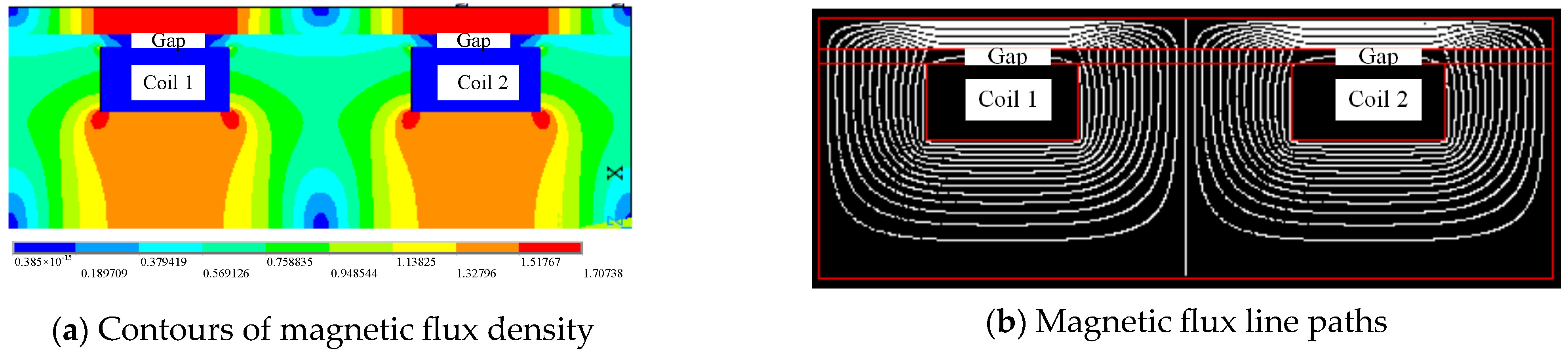
2.2. Magnetic Field Simulation of the MREA

The MRF-132DG from Lord Corp is used in this paper. Magnetic components of the damper are fabricated from 45 # steel. The magnetization characteristic data of 45 # steel and MRF-132DG are shown in Table 2 and Table 3. A finite element method is used to calculate flux density at each MR fluid gap. The total number of nodes is 326,400. Figure 2 shows the results of magnetic field simulation under a 2 A applied current. As shown in Figure 2a, the gap is exposed to the magnetic field. The magnetic flux lines have crossed perpendicularly through the gap, as shown in Figure 2b. The MR fluid yield shear stress in the gap could be rheologically affected by the magnetic flux when the MR fluid flows though the gap. Figure 3 shows that the arrangement of magnetic flux density results at different applied current. The value of magnetic flux increases with the increasing applied current. However, the value of magnetic flux at an applied 4 A current is only slightly higher than that at an applied 3 A current. The applied current of 4 A can be considered the saturation current, and the saturation flux density is 0.8 Tesla at this applied current.

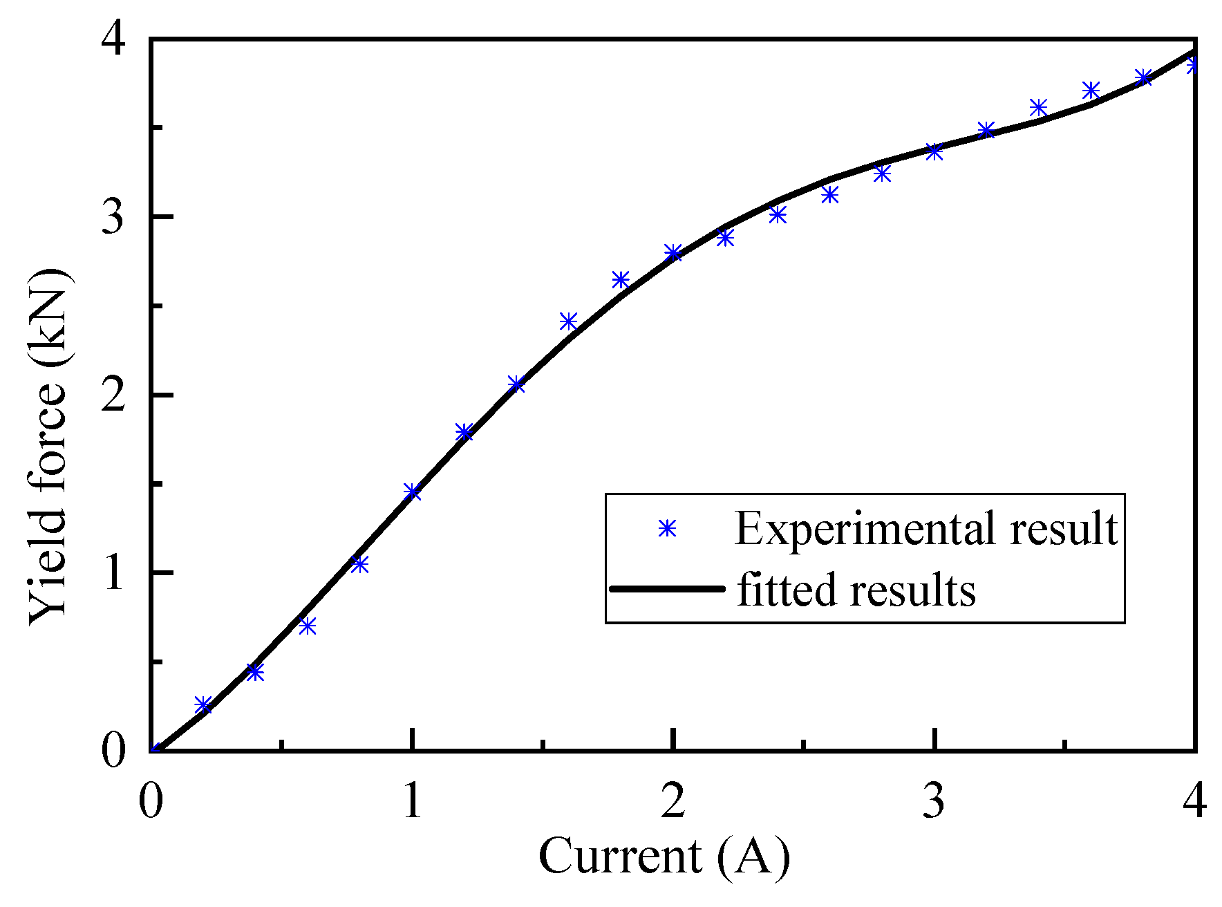
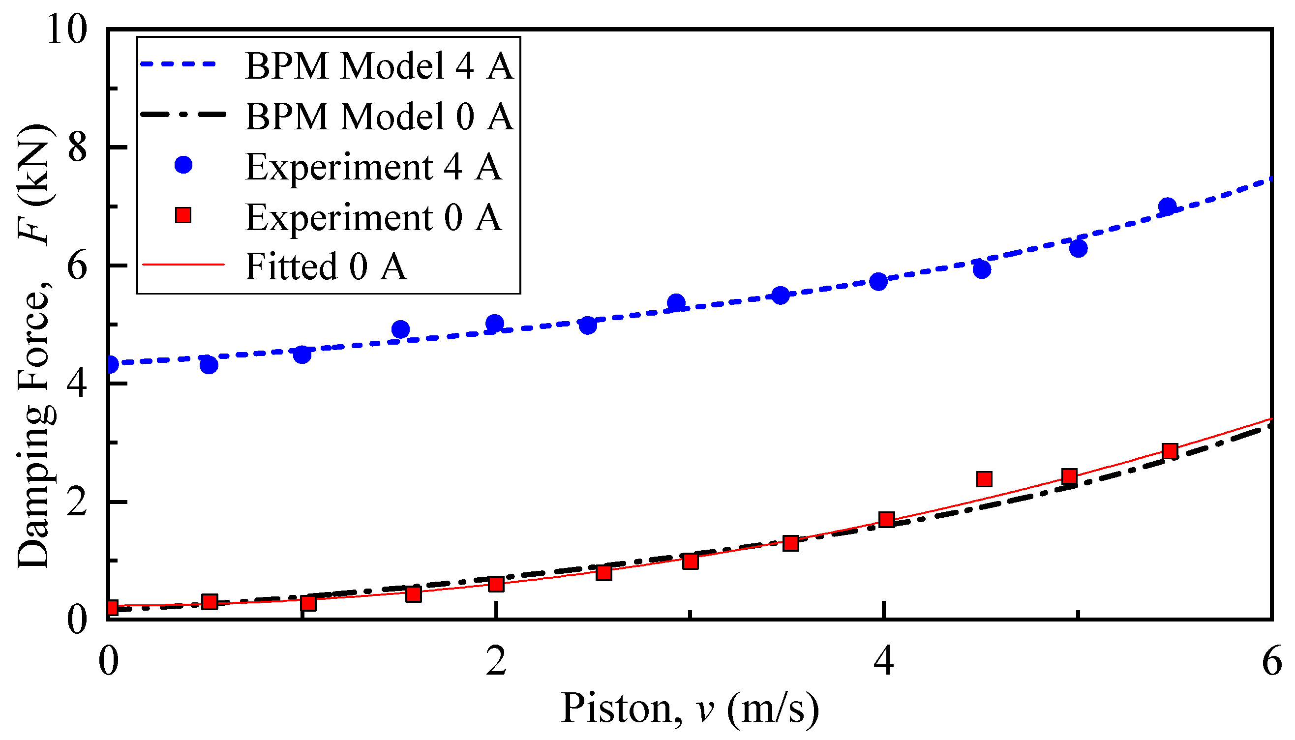
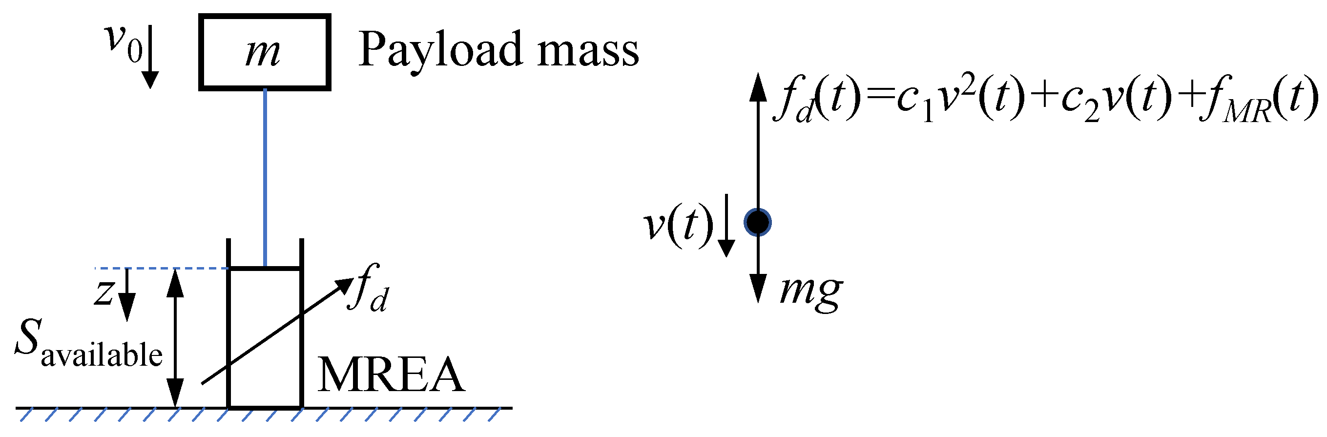
2.3. Damping Force Model of the MREA

Compared with the effective cross-sectional area of the piston, the annular gap is quite small so that the MR fluid flow velocity in the annular gap is amplified relative to piston velocity. When the piston velocity becomes large, the MR fluid flow inside the gap is complex. Singh et al. [33] established a Bingham–Plastic–Minor (BPM) model to describe the damping force characteristic of the MREA under an impact load. This model uses the Reynolds number of MR fluid in an annular gap to analyze the motion state of MR fluid. The damping force can be described as
F = ( Δ P η + Δ P m l ) A p + ( Δ P τ A p + F f ) s i g n ( v )
where ΔPη, ΔPml, and ΔPτ are the pressure drops due to viscous flow, minor losses, and the MR effect, respectively. Ap denotes the effective area of the piston. Ff is the friction force of the MREA, which can be measured by experiment. v is the piston velocity. The pressure drop due to the MR effect depends on the magnetic field in the annular gap. However, the fluid viscous pressure drop and minor loss pressure drop are a consequence of fluid flow. Ignoring friction force, the field-off pressure drop can be expressed as
Δ P f i e l d o f f = Δ P η + Δ P m l
When the current is applied in the MREA, the pressure drop of the MREA can be expressed as
Δ P f i e l d o n = Δ P f i e l d o f f + Δ P τ
The pressure drop caused by viscous flow in the MREA is
Δ P η = ρ 2 V g 2 f L 2 d
where f is the Darcy friction coefficient relating to the fluid flow state in the annular gap. Here, ρ is the density of the MR fluid, L is the total length of the annular gap, d is the width of the annular gap, and Vg is the mean fluid velocity. Note that Vg = ApVp/Ag, where Vp is the piston absolute velocity, Vp =|v|. Ag is the cross-sectional area of the annular gap, given by
A g = π 4 [ ( D i n + d ) 2 D i n 2 ]
The Reynolds number of the MR fluid in annular gap can be expressed as
R e = 2 ρ V g d η
where η is the viscosity of the MR fluid.
The MR fluid flow state in the annular gap is related to the Reynolds number. The Reynolds number is proportional to the velocity of the piston. When the piston velocity of the MREA is sufficiently low so that the Reynolds number is Re ≤ 2000, the MR fluid is in laminar flow state. The Darcy friction coefficient can be expressed as
f = 96 R e
When the Reynolds number is 2000 ≤ Re ≤ 4000, the MR fluid in an annular gap is in a transitional flow state. The Darcy friction coefficient can be expressed as
f = ( 1 α ) 96 2000 + α { 1.8 log 10 [ ( ε 3.7 D h ) 1.11 + 6.9 4000 ] } 2
where α is a constant and α = (Re − 2000)/(4000 − 2000). Here, ε is the average pipe wall roughness and was chosen to be 0.016 mm based on the wall roughness for drawn tubing given by Mao et al. [30]. Dh is the hydraulic diameter, and Dh = 2d.
When the velocity of a piston rod is so large that the Reynolds number is Re ≥ 4000, the MR fluid in an annular gap is in a turbulent flow state. The Darcy friction coefficient can be expressed as
1 f 1 2 1.8 log 10 [ ( ε 3.7 D h ) 1.11 + 6.9 R e ]
The pressure drop due to minor losses contains four components as in Figure 1:
(1)
Entrance effect for flow from region A1 to A2;
(2)
Exit effect for flow from region A2 to A3.
The total pressure drop due to a minor loss can be expressed as
Δ P m l = Δ P m l 12 + Δ P m l 23
where each pressure drop is given by
{ Δ P m l 12 = ρ 2 K E N V g 2 Δ P m l 67 = ρ 2 K E X V g 2
where KEN, KSE, KSC, and KEX represent the coefficients of the entrance effect, sudden expansion, sudden contraction, and exit effect, respectively, and can be written as
{ K E N = 0.42 ( 1 A g / A p ) K E X = ( 1 A g / A p ) 2

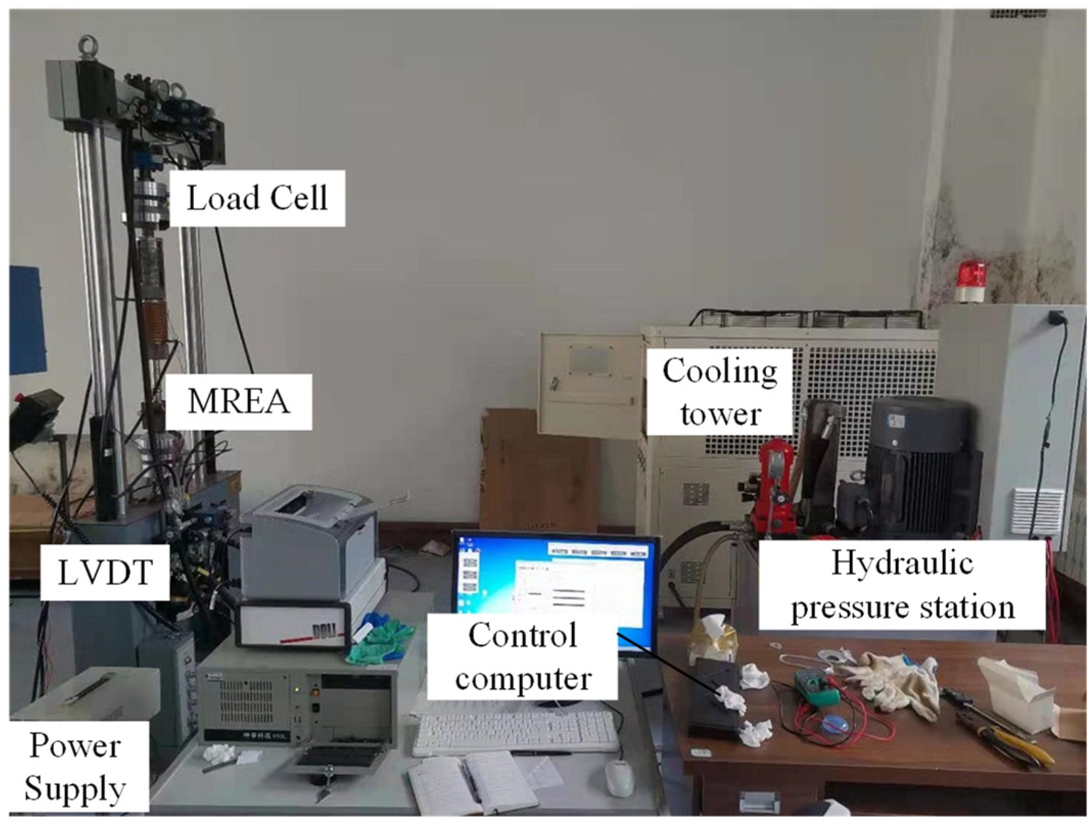
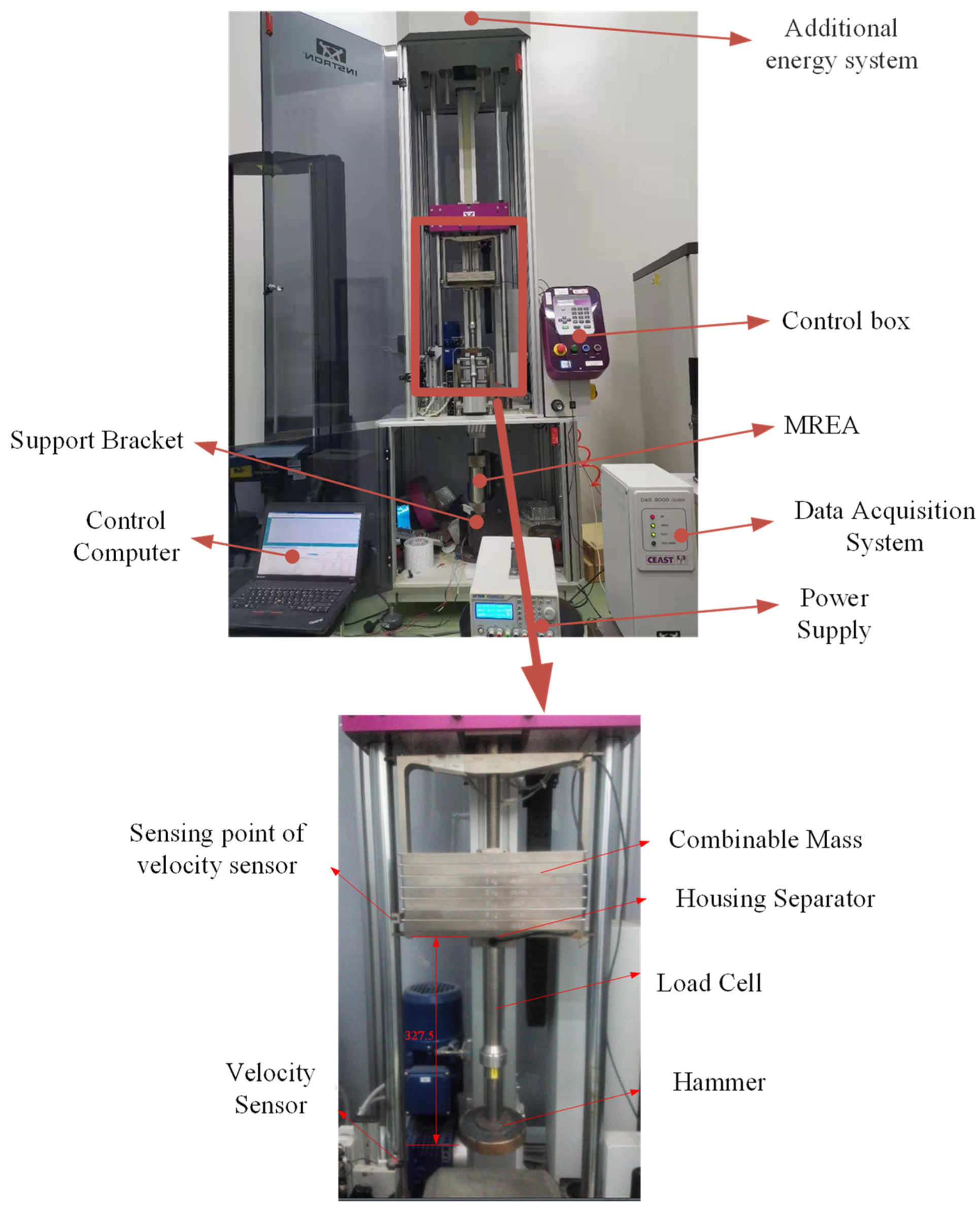
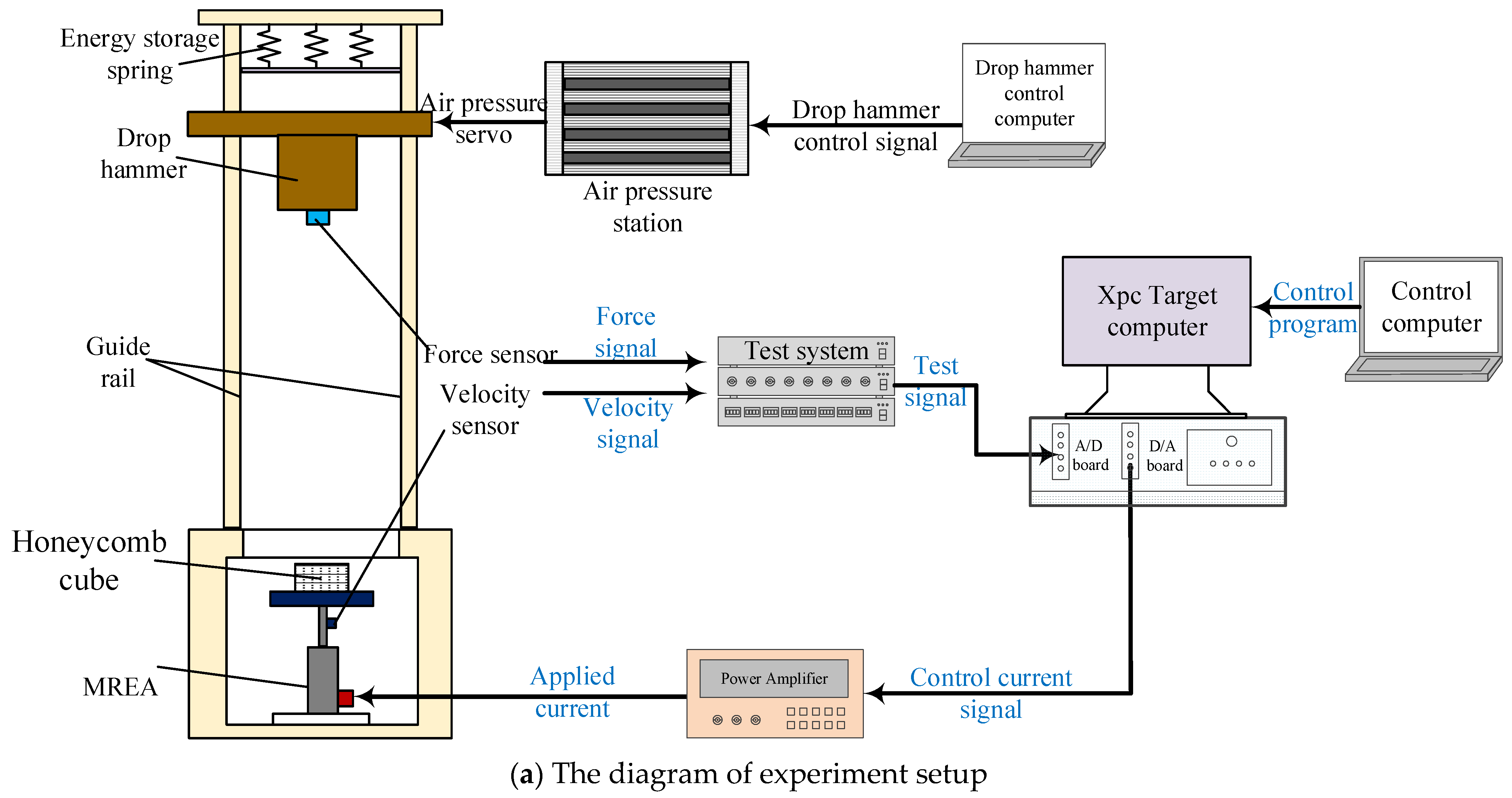
2.4. Experimental Setup for Damping Force

The test setup of the MREA yield force is shown in Figure 4. The test setup was based on an electro-servo-hydraulic fatigue testing machine. One side of the MREA was attached to a linear variable differential transformer (LVDT). The opposite side was attached to a load cell to measure the damper force. The electromagnetic coils in the MREA were activated by a power supply.
As shown in Equation (1), in addition to the viscous damping force Fv and yield force FMR, the output force of the MREA also includes the friction force Ff produced by the MREA seal on the piston rod. That is to say, F = Fv + FMR + Ff. The viscous damping force Fv is related to the piston velocity, while the yield force FMR and the friction force Ff are independent to the piston velocity. In order to measure the yield force under different applied currents, the piston should work at a quite low velocity for a long time. The MREA is excited using a low frequency triangular wave displacement. In this case, the viscous damping force Fv can be approximate considered as 0. The friction force Ff can be measured at 0 A applied current.
Figure 5 shows the tested damping force response of the MREA under triangular wave displacement excitation. The excitation frequency and amplitude are 0.05 Hz and 20 mm, respectively. The velocity of piston rod is v = 4fz = 0.004 m/s. The damping force of the MREA can be approximated as frictional force Ff at zero applied current condition. The friction force of the MREA developed in this study is Ff= 0.16 kN (I = 0 A in Figure 5). When the applied current is I = 1 A, the damping force is 1.6 kN. With the increase in applied current, the damping force of the MREA also increases monotonically. The damping force of the MREA is 3.96 kN at the maximum applied current of 4 A.
The yield force can be expressed as the difference between the total damping force and the friction force, that is,
F M R = F F f
Therefore, the relationship between yield force and applied current can be depicted in Figure 6. The mathematical relationship between yield force and current can be fitted to a polynomial, as shown in Equation (14). In Figure 6, the R-squared value is R2 = 0.9974, which shows the curve fits well.
F M R = 0.052 I 4 0.4016 I 3 + 0.7781 I 2 + 1.0299 I
The highspeed impact test was implemented on CEAST 9350 Drop Tower Impact Setup produced by INSTRON company, Boston, USA as shown in Figure 7. The impact setup contained a weight system and a data acquisition system. The weight system consisted of hammer, house separator, and combinable mass. The total mass of the weight system was the drop mass. The data acquisition system included data acquisition, velocity sensor, and load cell, which was used to measure hammer velocity and impact load. The damping force and piston velocity of the MREA can be directly read on the computer.
Figure 8 shows the damping force characteristic of the MREA under different piston velocities. The experimental observations are compared with BPM model. It can be seen the damping force predicted by BPM model agreed well with the experimental data. The BPM model can describe the damping force behavior accurately under high-speed impact. The damping force of the MREA at the applied current of 4 A was much larger than that at zero current. The damping force measured when the piston velocity was 5.0 m/s at the applied current of 4 A was 6.99 kN, which was about 2 times greater than that with no current supplied (3.49 kN). The damping force increased quadratically with piston velocity, as shown in Figure 8. A quadratic polynomial between damping force and piston velocity at 0 A applied current is shown in Equation (15), which, from Figure 8, accurately represents the measured data.
F ( I = 0   A ) = 90.33 V p 2 + 103.24 V p + 176.3
where Vp is the piston absolute velocity, Vp = |v|.

3. The Algorithm Design of Optimal Generalized Bingham Number Control

The drop-induced shock mitigation is presented in Figure 9 with an application of an MREA. The payload mass, m, is subjected to an initial drop velocity, v0. Here, the available stroke of the MREA is represented as Savailable. The governing equation of the drop system is
m z ¨ ( t ) = F ( t ) + m g
and the initial conditions are
z ( 0 ) = 0 ;   z ˙ ( 0 ) = v 0
where g is acceleration due to gravity (9.8 m/s2). Here, F(t) is the total damping force of the MREA:
F ( t ) = c 1 v 2 ( t ) + c 2 v ( t ) + F M R ( t )
The control objective is to obtain a soft landing by selecting an MR force or controllable damping force: the payload mass should come to rest after fully utilizing the available stroke. The non-dimensional generalized Bingham number (GBN) is defined as
B i = F M R c 1 v 0 2 + c 2 v 0
Here, we define a soft-landing control strategy with consideration of the MREA quadratic damping force with
v ˙ ( t ) = c 1 m v 2 ( t ) c 2 m v ( t ) F M R m + g = 1 τ v ( v v ¯ 1 ) ( v v ¯ 2 )
where τv = m/c1. Here, v ¯ 1 , 2 are the variables of the stroking load equation in Equation (20) and are related to
  v ¯ 1 , 2 = c 2 ± c 2 2 4 c 1 ( F M R m g ) 2 c 1 = c 2 ± Δ 2 c 1
In the application of the initial condition of v(t = 0) = v0 in Equation (20), the payload velocity is derived as
v ( t ) = v ¯ 1 + ( v 0 v ¯ 1 ) ( v ¯ 1 v ¯ 2 ) e ( v ¯ 1 v ¯ 2 ) t τ v ( v 0 v ¯ 2 ) ( v 0 v ¯ 1 ) e ( v ¯ 1 v ¯ 2 ) t τ v
In the application of the condition of z(t = 0) = 0 in Equation (22), the displacement of the payload can be obtained as
z ( t ) = v ¯ 1 t + τ v ln [ ( v 0 v ¯ 2 ) ( v 0 v ¯ 1 ) e ( v ¯ 1 v ¯ 2 ) t τ v ] τ v ln ( v ¯ 1 v ¯ 2 )
The GBN control algorithm consists of ensuring a soft landing as follows. For a soft landing to occur, the payload must come to a rest after fully utilizing the available MREA stroke. Assuming t1 as the total stroking time, at t = t1, the velocity and displacement of the pay-load should be v(t = t1) = 0 and z(t = t1) = Savailable. Submitting to Equations (22) and (23) yields
v ( t = t 1 ) = v ¯ 1 + ( v 0 v ¯ 1 ) ( v ¯ 1 v ¯ 2 ) e ( v ¯ 1 v ¯ 2 ) t 1 τ v ( v 0 v ¯ 2 ) ( v 0 v ¯ 1 ) e ( v ¯ 1 v ¯ 2 ) t 1 τ v = 0 ,
z ( t = t 1 ) = v ¯ 1 t 1 + τ v ln [ ( v 0 v ¯ 2 ) ( v 0 v ¯ 1 ) e ( v ¯ 1 v ¯ 2 ) t 1 τ v ] τ v ln ( v ¯ 1 v ¯ 2 ) = S a v a i l a b l e
With Equations (24) and (25), the optimal zeroes v ¯ 1 , 2 o and stroking time t1 can be calculated numerically. With a combination of Equation (21), the required yield force Fmr can be obtained as well as the GBN. A passive damping ce and spring ke are utilized for end-stop impact. The governing equation of the system is
m z ¨ ( t ) + c e z ˙ ( t ) + k e z ( t ) = F M R
with initial conditions of z ( t = t 1 ) = S a v a i l a b l e and z ˙ ( t 1 ) = v ( t = t 1 ) . The motion state can be assumed as a spring–damping–mass system as
z ( t ) = v n ω d e ζ ω n ( t t 1 ) sin [ ω d ( t t 1 ) ] + S a v a i l a b l e
v ( t ) = e ζ ω n ( t t 1 ) { ζ ω n v n ω d sin [ ω d ( t t 1 ) ] + v n cos [ ω d ( t t 1 ) ] }
a ( t ) = e ζ ω n ( t t 1 ) { ( ζ 2 ω n 2 v n ω d v n ω d ) sin [ ω d ( t t 1 ) ] 2 ζ ω n v n cos [ ω d ( t t 1 ) ] }
where z(t), v(t), and a(t) are the displacement, velocity, and acceleration. Here, vn is the non-zero payload velocity at the end of the available stroke. Also, we use the typical definitions of natural frequency, damping ratio, and damped natural frequency as below:
ω n = k e m ;   ζ = c e 2 m ω n ;   ω d = ω n 1 ζ 2
In the present simulation, the parameters are ke = 800 kN/m and ζ = 0.3.

4. Comparison of Control Effect between BN Control and GBN Control

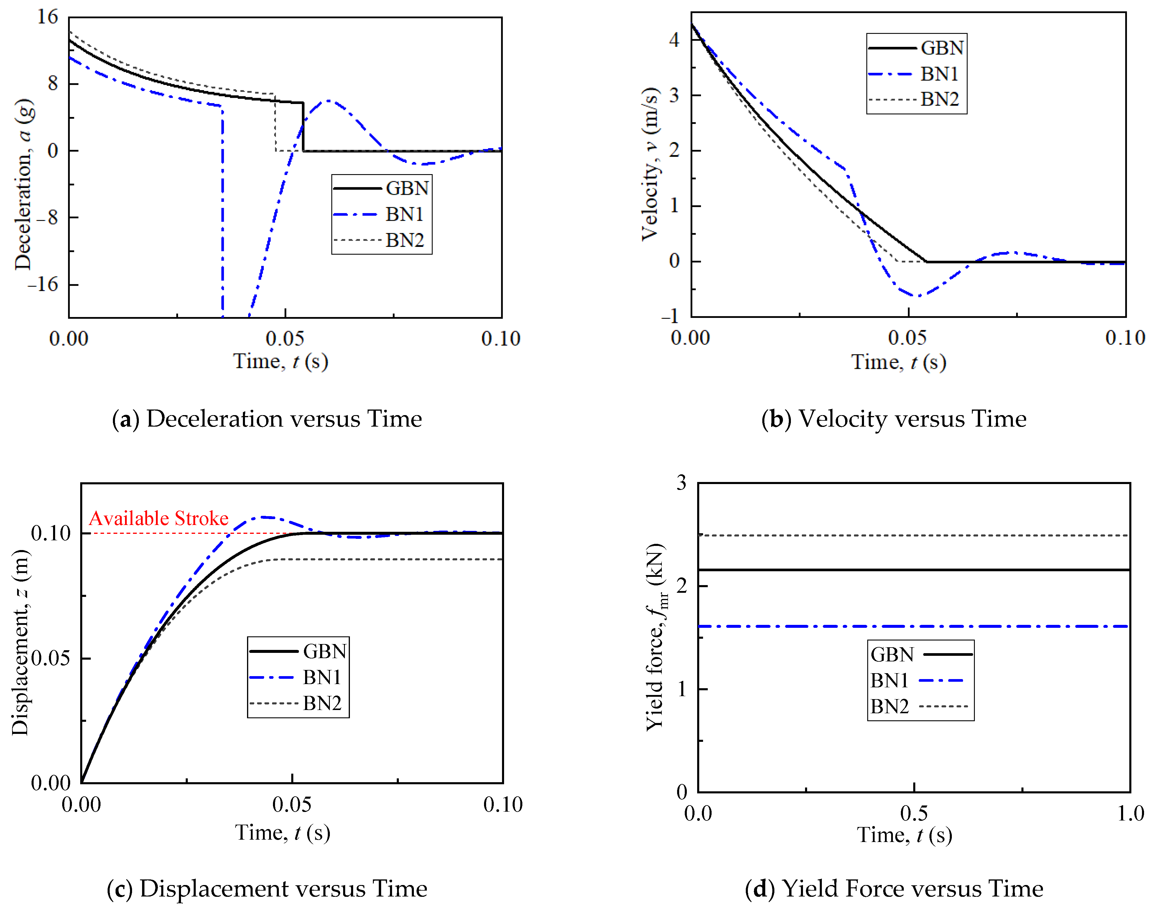
4.1. Simulation Results

An optimal Bingham number (BN) control method was proposed assuming post-yield linear damping [26]. However, we assumed that post-yield quadratic damping more accurately predicts field-off damping force, as shown in Section 2. In highspeed impacts, the relationship between impact velocity and field-off damping force becomes nonlinear because the flow in the gap transitions from the laminar to the turbulent state. In order to compare the controllability between the linear BN control method and nonlinear GBN control method, Figure 10 compares these two field-off damping force models. The quadratic damping parameters are given in Equation (15), and the two linear damping parameters are cl1 = 712.1 Ns/m and cl2 = 306.2 Ns/m, respectively. The field-off damping force predicted by linear damping model 1 is higher than the actual one, while the one predicted by linear damping model 2 is lower than the actual one. For simplification, we named these two BN control strategies based on linear damping models as BN1 and BN2.
Figure 11 shows the dynamic response of shock mitigation system under the BN control and GBN control. The initial drop velocity is 4.3 m/s. Under the GBN control, payload comes to a rest after it utilizes the total available stroke, i.e., a soft landing can be achieved.
Under the BN1 control, the controllable yield force is suboptimal (Figure 11d), i.e., the shock mitigation system underestimates the damping force, which implies that the payload cannot come to a rest after using the available stroke, leading to an end-stop impact. The payload reaches its available stroke with a remaining velocity of 1.67 m/s. The maximum end-stop deceleration reaches 22.7 g, which may result in payload damage. In the BN2 control, the controllable yield force is super optimal, i.e., the shock mitigation system overestimates damping force. The payload deceleration under the BN2 control is higher than that under the GBN control, which may increase the probability of payload damage. The payload comes to a rest at the stroke of 0.09 m, i.e., a soft landing cannot be achieved under the BN2 control using the entire available stroke.
The GBN control can achieve a soft landing with an optimal load-stroke profile. The controllable yield force of the linear BN control would cause either an end-stop impact or incomplete exploitation of the available stroke due to damping model inaccuracies.

4.2. Experimental Results

In this section, we build a prototype of semi-active drop hammer shock mitigation for rapid control to verify the soft-landing effect of the GBN control strategy. The drop hammer shock mitigation system setup is shown in Figure 12. As it can be seen from the diagram of experiment setup (Figure 12a), the experiment setup also contains two parts: the mechanical part and the semi-active control part. The mechanical part of the platform is CEAST 9350 drop tower, including an MREA. The MREA was attached firmly to the bottom of the drop tower. An aluminum honeycomb was attached on the top of the MREA piston rod to eliminate the ringing in the load cells due to metal-to-metal impact. The initial drop velocity is controlled by a drop hammer control computer. The drop height of the hammer can be set in the software and moved by air pressure servo. The semi-active control part includes sensors, control computer, Xpc real-time control system, test system, and a power amplifier, which supplies power to the MREA. The Xpc real-time control system is the core of the semi-active control system, including the A/D board, D/A board, Xpc target computer, and control computer.
The drop velocity and damping force can be measured by force and velocity sensors, respectively, and then, it transferred to an Xpc real-time control system through the test system. Note that the signal is an analog signal now, which can be converted to be a digital signal by the A/D board. The control program, as shown in Section 3, is completed on the control computer, compiled to generate the executable control code, and downloaded to the Xpc target computer. The control current can be calculated by a control program and converted to be an analog signal by the D/A board. Finally, the signal is amplified by a power amplifier and applied to the MREA.
In the test, the GBN or the BN1 or BN2 control algorithms are used to calculate the required yield force. The applied current is then calculated using Equation (14). Note that the friction force of the MREA is not considered in Section 3, so for practical purposes, the optimal yield force is given by
F M R _ r = F M R _ t F f
where FMR_r is the optimal yield force in practical control and FMR_t is the yield force calculated in Section 3. Here, Ff is the friction force of the MREA, and Ff = 0.16 kN. Table 4 shows the optimal yield force and control current for an initial one drop velocity of 4.3 m/s.
Figure 13 shows the experimental semi-active control performance of a shock mitigation system under the GBN control and BN control. For the GBN control, the hammer comes to a rest at the stroke of 10.26 cm, which is slightly over the available stroke of 10 cm, i.e., the soft landing can be achieved.
For the BN1 controller, the control current is so small, as shown in Table 4, that the damping force generated by the MREA is also lower than its optimal value (Figure 13a). In this case, the hammer has a non-zero velocity when it arrives at the available stroke of 10 cm and comes to a rest at the stroke of 13.2 cm at the end. The soft landing cannot be achieved under the BN1 control.
For the BN2 controller, the damping force generated by the MREA is higher than the optimal one under a higher control current. The hammer comes to a rest at the stroke of 8.37 cm, i.e., 83.7% of the available stroke. In this case, the payload is exposed to a higher deceleration due to the higher damping force, which increases the potential for payload damage.

5. Conclusions

This study proposed an optimal generalized Bingham number (GBN) control method to improve the soft-landing control accuracy of the drop-induced shock mitigation system using an MREA. The primary innovation was to recognize that post-yield damping for a high-impact speed linear stroke MREA is most likely quadratically proportional to piston velocity due to turbulent transition and minor loss effects. Our prior efforts assumed that post-yield damping was linearly proportional to piston velocity. An MREA was designed, modeled, fabricated, and tested to investigate the MREA damping force characteristic under a shock load. The dynamic equation of the single-degree-of-freedom shock mitigation system considering quadratic damping was established. A corresponding optimal GBN control strategy to achieve the soft-landing control objective was proposed, that is, to come to a rest after fully utilizing the available stroke with minimal or no end stop impact. The optimality of the GBN control algorithm was demonstrated via both simulation and experiments. The key conclusions are as follows:
  • The GBN control can achieve a soft landing accurately.
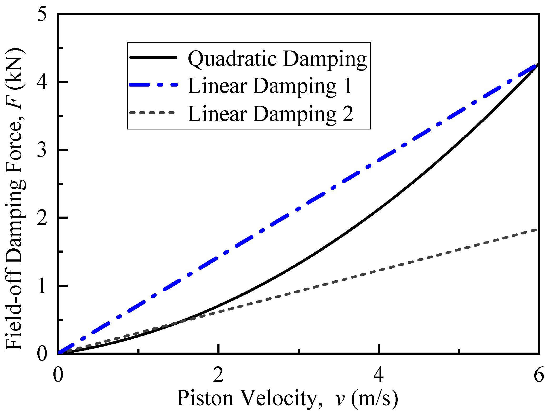
  • The damping force of an MREA is proportional to the square of piston velocity at high sink rate.
  • The quadratic GBN control strategy is superior to the linear BN control strategy in terms of soft-landing control accuracy. Limited by the accuracy of the damping force model, the BN control caused either an end-stop impact or incomplete exploitation of the available stroke.

Author Contributions

Conceptualization, M.W. and N.M.W.; methodology, M.W.; software, D.L. and Y.G.; validation, Y.X. and Y.G.; formal analysis, D.L.; investigation, M.W.; resources, D.L., Y.G. and B.L.; data curation, M.W.; writing—original draft preparation, M.W., Y.X. and N.M.W.; writing—review and editing, M.W., Y.X. and N.M.W.; visualization, D.L.; supervision, D.L.; project administration, D.L.; funding acquisition, D.L. All authors have read and agreed to the published version of the manuscript.

Funding

This work is supported by Science and Technology Program of CSEI (Grant No. 2021XKTD013) and the National Nature Science Foundation of China (Grant No. 12102319).

Institutional Review Board Statement

Not applicable.

Informed Consent Statement

Not applicable.

Data Availability Statement

The datasets generated during and/or analyzed during the current study are available from the corresponding author on reasonable request.

Conflicts of Interest

The authors declare they have no conflict of interest.

References

  1. Roshan, F.; Dashtimanesh, A.; Kujala, P. Safety Improvements for High-Speed Planing Craft Occupants: A Systematic Review. J. Mar. Sci. Eng. 2024, 12, 845. [Google Scholar] [CrossRef]
  2. Hughes, K.; Campbell, J.; Vignjevic, R. Application of the finite element method to predict the crashworthy response of a metallic helicopter under floor structure onto water. Int. J. Impact Eng. 2008, 35, 347–362. [Google Scholar] [CrossRef]
  3. Ghimire, A.; Hsu, C.H.; Lin, C.C.; Chen, P.Y. Hierarchical nested honeycomb-based energy absorbers: Design factors and tailorable mechanical properties. Interface Focus 2024, 14, 20230066. [Google Scholar] [CrossRef]
  4. Reid, S.R. Plastic deformation mechanisms in axially compressed metal tubes used as impact energy absorbers. Int. J. Mech. Sci. 1993, 35, 1035–1052. [Google Scholar] [CrossRef]
  5. Zhou, G.; Hill, M.D. Impact damage and energy-absorbing characteristics and residual in-plane compressive strength of honeycomb sandwich panels. J. Sandw. Struct. Mater. 2009, 11, 329–356. [Google Scholar] [CrossRef]
  6. Xu, P.; Zhao, H.; Yao, S.; Che, Q.; Xing, J.; Huang, Q.; Xu, K. Multi-objective optimisation of a honeycomb-filled composite energy absorber for subway vehicles. Int. J. Crashworthiness 2019, 25, 603–611. [Google Scholar] [CrossRef]
  7. Rakheja, S.; Afework, Y.; Sankar, S. An Analytical and Experimental Investigation of the Driver Seat Suspension. Syst. Veh. Syst. Dyn. 1994, 23, 501–524. [Google Scholar] [CrossRef]
  8. Jackson, K.E.; Fasanella, E.L.; Boitnott, R.; McEntire, J.; Lewis, A. Occupant Responses in a Full-Scale Crash Test of the Sikorsky ACAP Helicopter. J. Am. Helicopter Soc. 2004, 49, 127–139. [Google Scholar] [CrossRef]
  9. Dyke, S.J.; Spencer, B.F.; Sain, M.K.; Carlson, J.D. Modeling and control of magnetorheological dampers for seismic response reduction. Smart Mater. Struct. 1996, 5, 565–575. [Google Scholar] [CrossRef]
  10. Wang, M.; Chen, Z.; Wereley, N.M. Magnetorheological damper design to improve vibration mitigation under a volume constraint. Smart Mater. Struct. 2019, 28, 114003. [Google Scholar] [CrossRef]
  11. Kong, G.; Ouyang, Q.; Hu, H.; Xiang, W.; Zhao, W. Structural Design and Controllability of Magnetorheological Grease Buffers under Impact Loading. Materials 2023, 16, 4724. [Google Scholar] [CrossRef]
  12. Shou, M.; Liao, C.; Yang, P.-A.; Huang, X.; Wu, D.; Zhou, Z.; Luo, J.; Li, R. Hybrid modeling of the nonlinear behaviors for magnetorheological energy absorber. Hybrid modeling of the nonlinear behaviors for magnetorheological energy absorber. Int. J. Mech. Sci. 2023, 243, 107820. [Google Scholar] [CrossRef]
  13. Ouyang, Q.; Zheng, J.; Li, Z.; Hu, M.; Wang, J. Controllability analysis and testing of a novel magnetorheological absorber for field gun recoil mitigation. Smart Mater. Struct. 2016, 25, 115041. [Google Scholar] [CrossRef]
  14. Singh, H.J.; Wereley, N.M. Optimal control of gun recoil in direct fire using magnetorheological absorbers. Smart Mater. Struct. 2014, 23, 055009. [Google Scholar] [CrossRef]
  15. Choi, Y.T.; Robinson, R.; Hu, W.; Wereley, N.M.; Birchette, T.S.; Bolukbasi, A.O.; Woodhouse, J. Analysis and control of a magnetorheological landing gear system for a helicopter. J. Am. Helicopter Soc. 2016, 61, 1–8. [Google Scholar] [CrossRef]
  16. Ahuré-Powell, L.A.; Choi, Y.T.; Hu, W.; Wereley, N.M. Nonlinear Modeling of Adaptive Magnetorheological Landing Gear Dampers under Impact Conditions. Smart Mater. Struct. 2016, 25, 115011. [Google Scholar] [CrossRef]
  17. Saleh, M.; Sedaghati, R.; Bhat, R. Dynamic analysis of an SDOF helicopter model featuring skid landing gear and an MR damper by considering the rotor lift factor and a Bingham number. Smart Mater. Struct. 2018, 27, 065013. [Google Scholar] [CrossRef]
  18. Kang, B.K.; Choi, S.B. Design, structure analysis and shock control of aircraft landing gear system with MR damper. Smart Mater. Struct. 2024, 33, 055049. [Google Scholar] [CrossRef]
  19. Han, C.; Kang, B.-H.; Choi, S.-B.; Tak, J.M.; Hwang, J.-H. Control of landing efficiency of an aircraft landing gear system with magnetorheological dampers. J. Aircr. 2019, 56, 1980–1986. [Google Scholar] [CrossRef]
  20. Luong, Q.V.; Jang, D.S.; Hwang, J.H. Robust adaptive control for an aircraft landing gear equipped with a magnetorheological damper. Appl. Sci. 2020, 10, 1459. [Google Scholar] [CrossRef]
  21. Luong, Q.V.; Jang, D.S.; Hwang, J.H. Intelligent Control based on a neural network for aircraft landing gear with a magnetorheological damper in different landing scenarios. Appl. Sci. 2020, 10, 5962. [Google Scholar] [CrossRef]
  22. Luong, Q.V.; Jo, B.H.; Hwang, J.H.; Jang, D.-S. A Supervised Neural Network Control for Magnetorheological Damper in an Aircraft Landing Gear. Appl. Sci. 2021, 12, 400. [Google Scholar] [CrossRef]
  23. Wang, C.; Nie, H.; Chen, J.; Lee, H.P. The design and dynamic analysis of a lunar lander with semi-active control. Acta Astronaut. 2019, 157, 145–156. [Google Scholar] [CrossRef]
  24. Wang, C.; Chen, J.; Li, X.; Chen, H.; Nie, H.; Lin, F. Design, dynamic analysis, and experiments of MRF dampers for lunar landers. Adv. Space Res. 2021, 68, 3012–3025. [Google Scholar] [CrossRef]
  25. Bai, X.X.; Yang, S. Hybrid controller of magnetorheological semi-active seat suspension system for both shock and vibration mitigation. J. Intell. Mater. Syst. Struct. 2019, 30, 1613–1628. [Google Scholar] [CrossRef]
  26. Wereley, N.M.; Choi, Y.-T.; Singh, H.J. Adaptive energy absorbers for drop-induced shock mitigation. J. Intell. Mater. Syst. Struct. 2011, 22, 515–519. [Google Scholar] [CrossRef]
  27. Choi, Y.-T.; Wereley, N.M. Drop-induced shock mitigation using adaptive magnetorheological energy absorber incorporating a time lag. ASME J. Vib. Acoust. 2015, 137, 01101. [Google Scholar] [CrossRef]
  28. Wang, M.; Chen, Z.; Wereley, N.M. Adaptive magnetorheological energy absorber control method for drop-induced shock mitigation. J. Intell. Mater. Syst. Struct. 2021, 32, 449–461. [Google Scholar] [CrossRef]
  29. Saleh, M.; Sedaghati, R.; Bhat, R. Design optimization of a bi-fold MR energy absorber subjected to impact loading for skid landing gear applications. Smart Mater. Struct. 2019, 28, 035031. [Google Scholar] [CrossRef]
  30. Mao, M.; Hu, W.; Choi, Y.-T.; Wereley, N.; Browne, A.L.; Ulicny, J. Experimental validation of a magnetorheological energy absorber design analysis. J. Intell. Mater. Syst. Struct. 2014, 25, 352–363. [Google Scholar] [CrossRef]
  31. Bai, X.X.; Hu, W.; Wereley, N.M. Magnetorheological damper utilizing an inner bypass for ground vehicle suspensions. IEEE Trans. Magn. 2013, 49, 3422–3425. [Google Scholar] [CrossRef]
  32. Wang, M.; Chen, Z.; Yan, H.; Choi, Y.-T.; Wereley, N.M. Optimal control of drop-induced shock mitigation using magnetorheological energy absorbers considering quadratic damping. J. Intell. Mater. Syst. Struct. 2021, 32, 1504–1517. [Google Scholar] [CrossRef]
  33. Singh, H.J.; Hu, W.; Wereley, N.M.; Glass, W. Experimental validation of a magnetorheological energy absorber design optimized for shock and impact loads. Smart Mater. Struct. 2014, 23, 125033. [Google Scholar] [CrossRef]
Figure 1. The double-ended MR damper configuration with two electromagnetic coils. 1—Upper piston rod, 2—piston core, 3—electromagnetic coil, 4—piston cylinder, 5—hydraulic cylinder, 6—MR fluid, 7—underneath piston rod, 8—piston, 9—seal ring, and 10—hydraulic cylinder seal cap.
Applsci 14 07317 g001
Figure 2. Magnetic analysis results with 2 A applied current.
Applsci 14 07317 g002
Figure 3. Magnetic flux density with various applied current.
Applsci 14 07317 g003
Figure 4. Experimental setup for the yield force of MREA.
Applsci 14 07317 g004
Figure 5. The MREA yield force characteristic under triangular excitation.
Applsci 14 07317 g005
Figure 6. Yield force vs. applied current.
Applsci 14 07317 g006
Figure 7. MREA high-speed drop hammer experiment setup.
Applsci 14 07317 g007
Figure 8. MREA damping force vs. velocity.
Applsci 14 07317 g008
Figure 9. A configuration of the MREA for drop-induced shock mitigation.
Applsci 14 07317 g009
Figure 10. Comparison of linear and nonlinear field-off damping force characteristics of MREA.
Applsci 14 07317 g010
Figure 11. Dynamic response of shock mitigation system under different control algorithms.
Applsci 14 07317 g011
Figure 12. Semi-active drop hammer shock mitigation for rapid control experiment setup.
Applsci 14 07317 g012aApplsci 14 07317 g012b
Figure 13. Comparison of experimental results between BN controller and GBN controller.
Applsci 14 07317 g013
Table 1. The design parameters of the MREA.
ParameterSymbolValue
Diameter of the cylinder (m)Dp63 × 10−3
Diameter of piston (m)Din49 × 10−3
Diameter of piston rod (m)Dr30 × 10−3
Length of magnetic core (m)La30 × 10−3
Length of coil (m)Lc30 × 10−3
Thickness of gap (m)d2.5 × 10−3
Turns of coil winding (Turns)N400
Table 2. Magnetization characteristic data of 45” steel.
Magnetic Field Intensity, H (A/m)Magnetic Flux Density, B (T)
1640.2
2450.4
3650.6
5450.8
8131
12131.2
18091.4
29961.6
Table 3. Magnetization characteristic data of MRF-132DG.
Magnetic Field Intensity, H (kA/m)Magnetic Flux Density, B (T)
100.088
300.221
500.35
700.437
900.527
1100.59
1300.653
1500.7
1700.75
2000.829
2400.91
2801.103
3201.108
Table 4. The optimal yield force and control current in a real case.
Control MethodYield Force (kN)Control Current (A)
GBN1.9941.366
BN11.3340.937
BN22.332.33
Disclaimer/Publisher’s Note: The statements, opinions and data contained in all publications are solely those of the individual author(s) and contributor(s) and not of MDPI and/or the editor(s). MDPI and/or the editor(s) disclaim responsibility for any injury to people or property resulting from any ideas, methods, instructions or products referred to in the content.

