Article

Combustion Test for the Smallest Reciprocating Piston Internal Combustion Engine with HCCI on the Millimeter Scale

1
College of Mechanical Engineering, North China University of Water Resources and Electric Power, Zhengzhou 450045, China
2
College of Mechanical and Vehicle Engineering, Chongqing University, Chongqing 400044, China
3
State Key Laboratory of Mechanical Transmission, Chongqing University, Chongqing 400044, China
4
Department of Mechanical Engineering, Eindhoven University of Technology, NL 5600 Eindhoven, The Netherlands
*
Author to whom correspondence should be addressed.
Appl. Sci. 2024, 14(16), 7359; https://doi.org/10.3390/app14167359 (registering DOI)
Submission received: 14 July 2024 / Revised: 8 August 2024 / Accepted: 19 August 2024 / Published: 21 August 2024
(This article belongs to the Section Applied Thermal Engineering)

Abstract

:
Micro reciprocating piston internal combustion engines are potentially desirable for high-energy density micro power sources. However, complex subsystem functions hinder the downsizing of reciprocating piston internal combustion engines. The homogeneous charge compression-ignition (HCCI) combustion mode requires no external ignition system; it contributes to structural simplification of the reciprocating piston internal combustion engines under a micro space constraint but has not been adequately verified at the millimeter scale. The study used a millimeter-scale HCCI reciprocating piston internal combustion engine fueled by a mixture of kerosene, ether, castor oil, and isopropyl nitrate for combustion investigation. The test engine with a displacement of 0.547 cc is the smallest reciprocating piston internal combustion engine known to have undergone in-cylinder combustion diagnosis. It is observed that the HCCI combustion mode at the millimeter scale can realize stable combustion with excellent cooperation for the thermodynamic cycle under appropriate structural and operating conditions, which is essentially not inferior to those in conventional-sized reciprocating piston internal combustion engines. This finding helps the next step of scaling down reciprocating piston internal combustion engines.

1. Introduction

Micro power systems exhibit promise in micro air vehicles, autonomous micro-robots, etc. [1,2,3]. Compared to other micro power systems such as micro-thermoelectric, -photovoltaic, -piezoelectric, and -magnetoelectric, micro-heat engines based on liquid hydrocarbon fuels have an advantage in terms of energy density that is 20–30 times more than the energy density characteristics of today’s best LiSO2 battery systems [4,5,6]. Currently, most micro heat engines come from the scaling-down of macro-scale heat engines, such as micro gas turbine engines, micro rotary Wankel engines, micro free-piston engines, micro Rankine-cycle steam engines, micro-Stirling engines, etc. [7,8,9,10,11]. Very few micro power system concepts are derived from novel thermodynamic principles [12,13,14]. Of these, downsized reciprocating piston internal combustion engines are of considerable interest because they are very close to being realized, with manufactured centimeter-scale and even millimeter-scale prototypes for commercial applications [15,16].
Scaled-down miniature reciprocating piston internal combustion engines are characterized by two-stroke, single-cylinder, air-cooled, cross-scavenged, glow ignition, or compression ignition. However, the scale effect results in more gas leakage from the combustion chamber, growing friction and heat transfer losses, abnormal flame quenching, and incomplete combustion [17,18]. Menon et al. conducted performance tests on nine miniature glow ignition reciprocating piston internal combustion engines and indicated that the thermal efficiencies decreased rapidly when the engine displacement was downsized to 10 cc, with combustion losses accounting for 65% of the total energy loss [19,20]. In response, the in-cylinder combustion of miniature reciprocating piston internal combustion engines was explored in depth. Raine et al. tested a platinum wire glow ignition miniature internal combustion engine with a displacement of 7.4 cc and investigated the effects of nitromethane additives, air/fuel ratios, and the structure of platinum wire ignition plugs on the performance and combustion stability [21]. Collair et al. performed combustion tests on a homogeneous charge compression ignition (HCCI) miniature internal combustion engine with a displacement of 6.5 cc and investigated the in-cylinder combustion at different speeds and loads [22]. Manente et al. tested an HCCI miniature internal combustion engine with a displacement of 4.1 cc and investigated the effects of compression ratio, cylinder head temperature, and the shape of the combustion chamber on the in-cylinder combustion [23,24]. Lei et al. tested a glow ignition miniature internal combustion engine with a displacement of 1.5 cc and diagnosed the in-cylinder combustion characterized by the low indicated mean efficient pressure (pmi) and severe cyclic variations [25]. Shang et al. diagnosed the in-cylinder combustion of a glow ignition miniature internal combustion engine with a displacement of 0.99 cc, pointed out the imperfection of lagging combustion time, long combustion duration, and sizeable cyclic variation, and tried to improve in-cylinder combustion by fuel additives (nitromethane, hydrogen peroxide, etc.) and platinum wire glow intensity [26,27,28].
Miniature reciprocating piston internal combustion engines are fueled by the methanol–nitromethane mixture in the glow ignition combustion mode and the ether–kerosene combination in the HCCI combustion mode. Both blended fuels add castor oil as a lubricant. Under the HCCI combustion mode, the air–fuel mixture is ignited simultaneously at multiple points; thus, the combustion rate is higher. In addition, no flame quenching happens due to the absence of flame propagation, and no external ignition needs to be installed. These characteristics make the HCCI combustion mode more adaptable to a tiny space [29,30,31]. However, in the HCCI combustion mode, miniature reciprocating piston internal combustion engines lack mandatory control of the combustion process (e.g., without the ignition timing or fuel-injection timing control that are in macro-scale internal combustion engines), and the chemical kinetic reaction rate determines the combustion initiation, phase, and duration. As dimensions are scaled down to the millimeter scale, the area-to-volume ratio should increase by orders of magnitude, resulting in more heat transfer, friction, and blow-by losses. However, combustion diagnosis on a millimeter-scale HCCI reciprocating piston internal combustion engine has never been reported, and the feasibility of developing the HCCI combustion mode at the millimeter scale needs to be verified.
In the presented work, a millimeter-scale HCCI reciprocating piston internal combustion engine with a bore of 9.0 mm and a stroke of 8.6 mm was remodeled and subjected to combustion diagnosis. Notably, the test engine with a displacement of 0.547 cc is the smallest reciprocating piston internal combustion engine conducting in-cylinder combustion diagnosis to date. The presented work comprehensively monitored the combustion process of the test engine, demonstrated the effect of compression ratio, thermal state, and intake pressure on the in-cylinder combustion, and verified the feasible operating of the HCCI combustion mode at the millimeter scale.

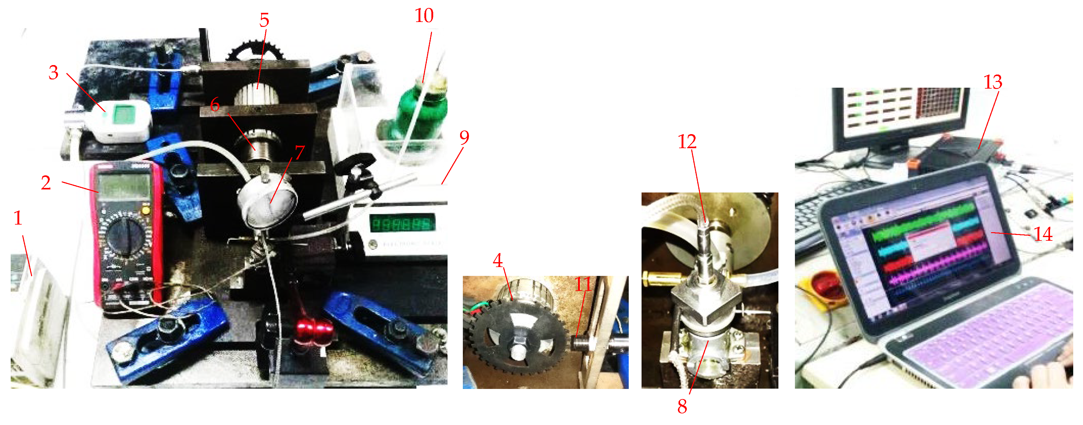
2. Materials and Methods

As shown in Figure 1, a test bench consists of a motor-driven, a load-absorbing, and a data acquisition subsystem, and the test engine. The motor, hysteresis brake, and test engine are mounted in series on the base plate through couplings. The motor is a drive unit that drives the entire system to rotate at a specified speed. The hysteresis brake acts as a load-absorbing device that balances the test engine’s output torque and the motor’s driving torque. A frequency converter regulates the motor speed by changing the frequency and voltage, whose output frequency can be adjusted from 0 Hz to 600 Hz. The hysteresis brake can deliver a maximum of 200 W of braking power under the forced cooling condition and with a linear relationship between the control current and braking torque. An adjustable DC-regulated power supply is used to control the input current of the hysteresis brake for the braking torque regulation. The test bench is also equipped with a photoelectric tachometer (DT2234B, SUWEI Electronic Technology, Shenzhen, China), a K-type thermocouple (DM6801A, VICTOR Instrument, Shenzhen, China), and a micro-flow meter (MF5706-N-25, SIARGO Ltd., Milpitas, CA, USA) for measurement of the operating parameters, such as engine speed, cylinder block temperature, and intake flow. In addition, a weighing method is used to measure fuel consumption. A more detailed principle and layout diagrams for the test bench can also be found in References [18,32].
A piezoelectric crystal pressure transducer (6052B, Kistler, Winterthur, Switzerland) converts the in-cylinder combustion pressure into a charge signal. The pressure sensor has a sensitivity of −20.06 pC/bar and does not vary by more than ± 0.5% over a temperature range of 150 °C to 250 °C. The pressure sensor can be mounted on the cylinder head of the test engine with a 5 mm threaded hole. The crank angle is identified by a 36-1 gear disc coaxially coupled to the crankshaft of the test engine. A Hall sensor (MP-935, ONO SOKKI, Yokohama, Japan) converts the change in the magnetic field due to the rotation of the toothed disc into a voltage signal that will be conditioned into a sawtooth square wave of 0.1 deg crank angle (CA) by a pulse multiplication algorithm built in a data analysis software suite that will be described later. The combustion pressure and crank angle signals are sent to a data acquisition module (SIRIUSi-HS, DEWEsoft, Ver. SP5) characterized by high-bandwidth transient recording (15 MS/s) and an ultra-high dynamic, anti-aliasing data sample. Based on the in-cylinder combustion pressure and crank angle signals, a software suite (X3, DEWEsoft, Ver. SP5) uses a zero-dimensional thermodynamic model to analyze the in-cylinder combustion in real time and calculate the combustion parameters and their statistical characteristics. Moreover, the top dead center (TDC) is thermodynamically determined from the in-cylinder pressures of the motored test engine, and pressure signal drift due to temperature changes is eliminated using a thermodynamic zero-point correction method. Table 1 gives the technical data of these measuring instruments.
The test engine is a single-cylinder, air-cooled, two-stroke reciprocating piston internal combustion engine with a displacement of 0.547 cc. The cylinder bore and stroke of the test engine are 9.0 mm and 8.6 mm, respectively, in the millimeter-scale range. The test engine uses the HCCI combustion mode fueled by a mixture of 40% kerosene, 34% ether, 24% castor oil, and 2% isopropyl nitrate (isopropyl nitrate is used for ignition improver). The fuel properties are shown in Table 2. The test engine was remodeled for in-cylinder combustion diagnostics. As shown in Figure 2, the pressure sensor is mounted on the cylinder head through a 5 mm threaded hole, and then a clamp nut fixes the cylinder head on an adjusting nut. The adjusting nut could be screwed into or out of the cylinder through the thread on the outer wall of the cylinder. When the adjusting nut is screwed down, the cylinder head moves downward with the adjusting nut and the clamp nut, the volume of the combustion chamber decreases, and the compression ratio (CR) increases. When the adjusting nut is screwed up, the adjusting nut, fastening nut, and cylinder head move upward together, the combustion chamber volume increases, and the compression ratio decreases. The limiting position of the downward movement of the adjusting nut is set as a reference zero point, where the combustion chamber volume is minimized. Owing to a 9.88 mm3 channel volume in front of the pressure sensor, the zero point position corresponds to a maximum theoretical compression ratio of 56.4. The thread pitch of the adjusting nut is 0.8 mm, so for every 45 degrees (1/8 turn) of rotation of the adjusting nut, the cylinder head will move up or down 0.1 mm. The combustion chamber volumes and compression ratios as the adjusting nut is turned upward are shown in Table 3.
The test bench utilizes a centrifugal fan for forced air cooling of the test engine. The cylinder block temperature can be controlled to a preset value by adjusting the cooling air flow rate. In addition, the test bench is equipped with an intake pressurization unit, including a pressure-stabilizing tank, an air pump, a pressure regulator valve, and a pressure regulator box. Boosted by an air pump downstream of the pressure-stabilizing tank, the intake air can be adjusted to a preset pressure in the pressure regulator box by controlling the opening of the pressure regulator valve. Intake flow is measured between the pressure-stabilizing tank and the air pump, and intake pressure is measured at the pressure regulator box. During the tests, the engine speed was set to 6000 r/min, the throttle was fully open, and the carburetor was calibrated to make the test engine present the maximum pmi and an approximate fuel/air equivalence ratio of 1.2. Keeping the same baseline operating condition unchanged, the in-cylinder combustion at different compression ratios, thermal statuses, and intake pressures was investigated.

3. Results and Discussions

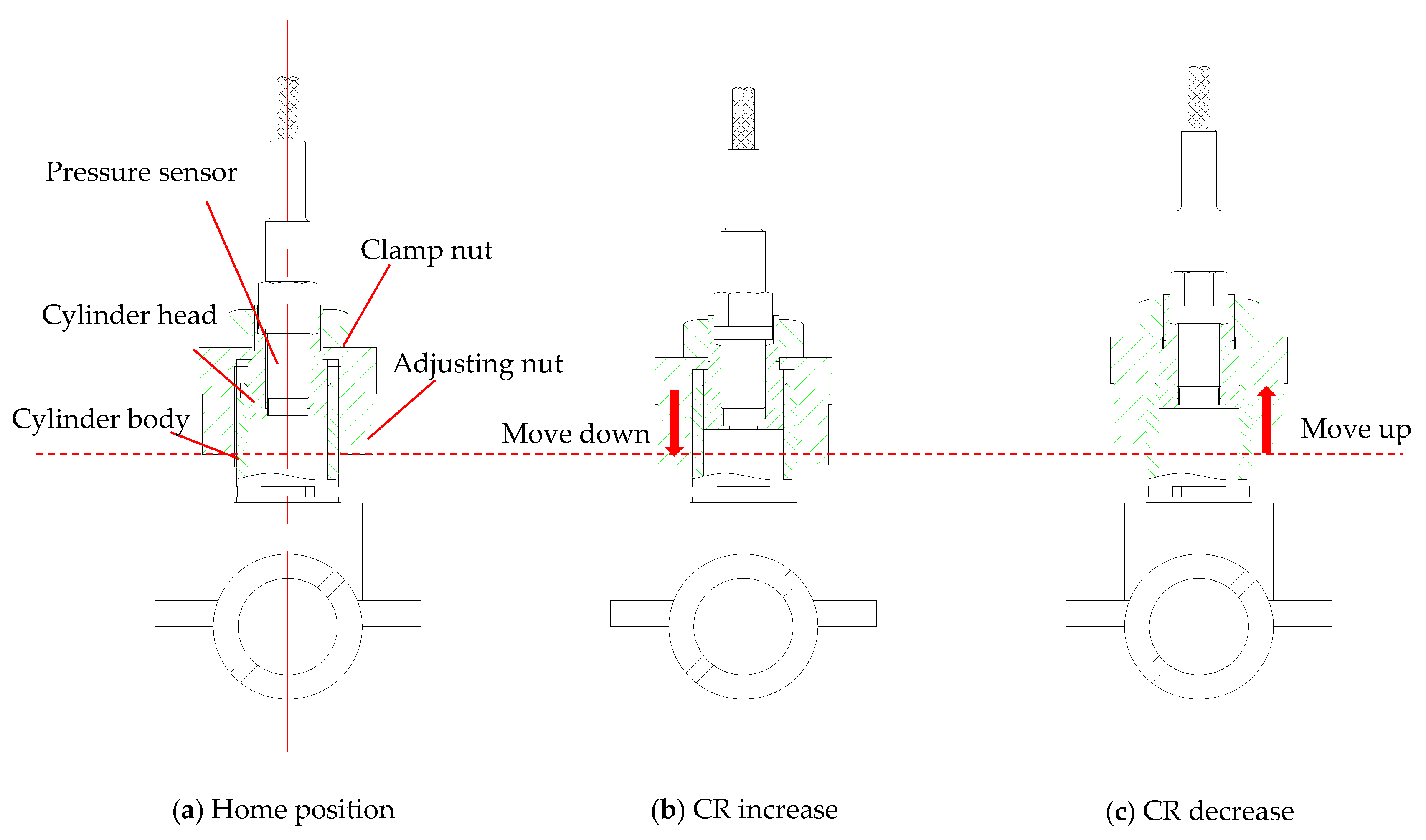
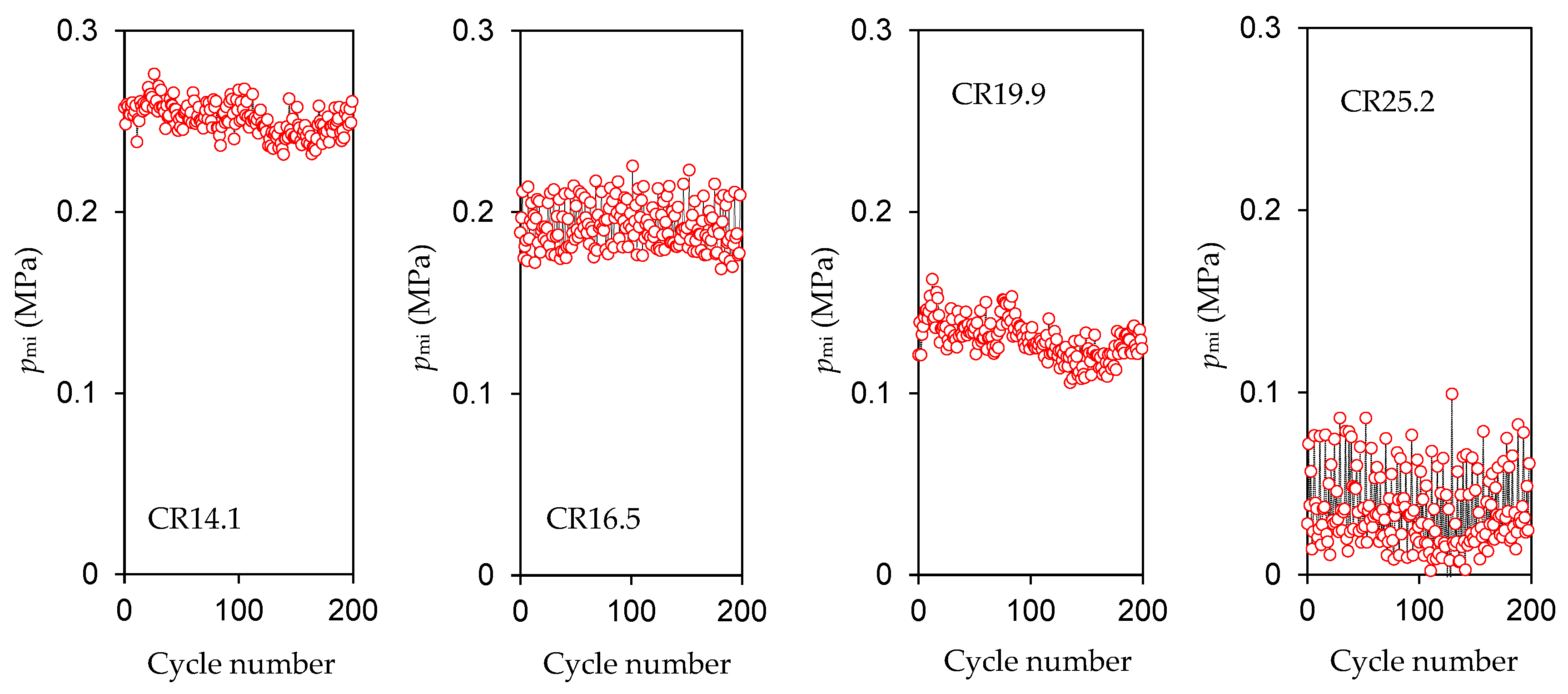
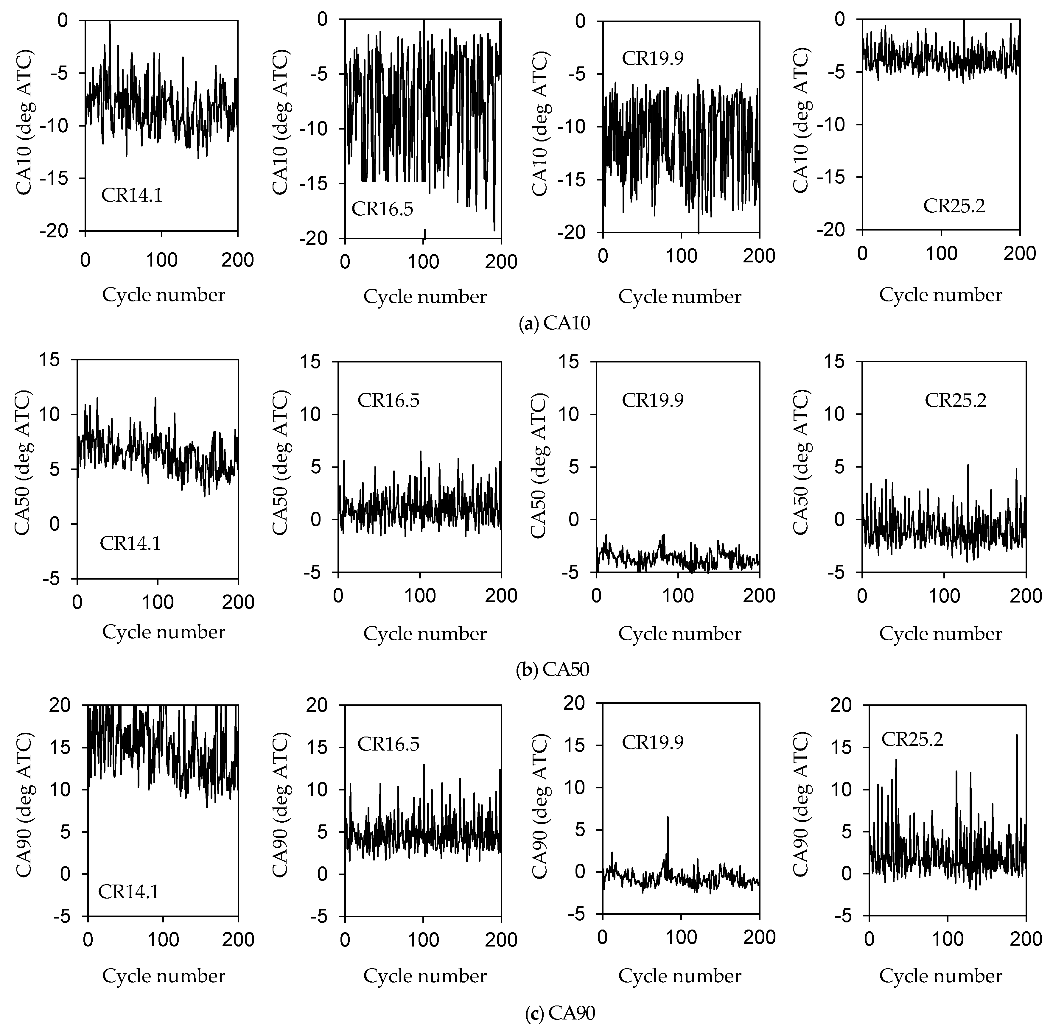
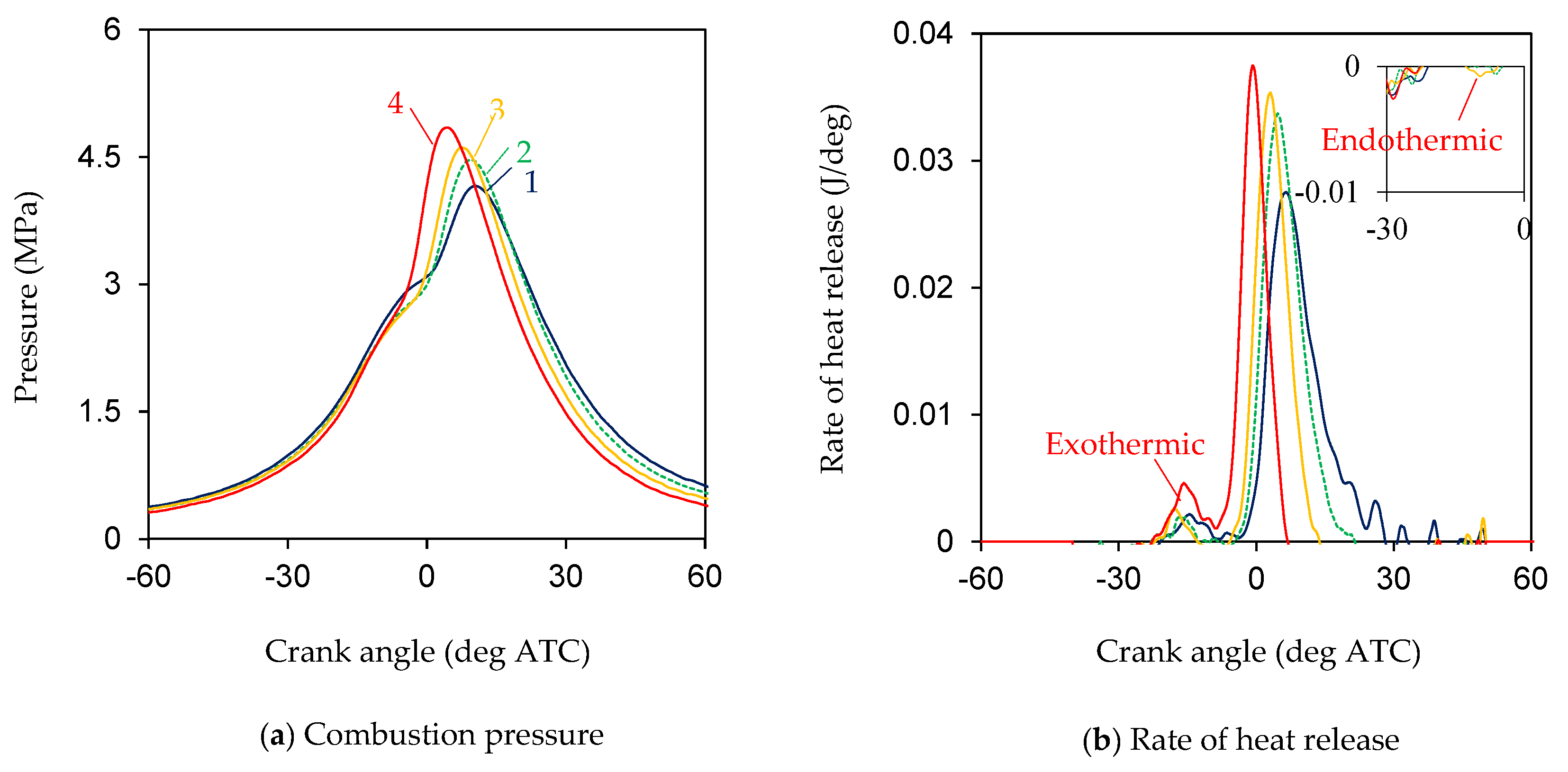
3.1. Compression Ratio
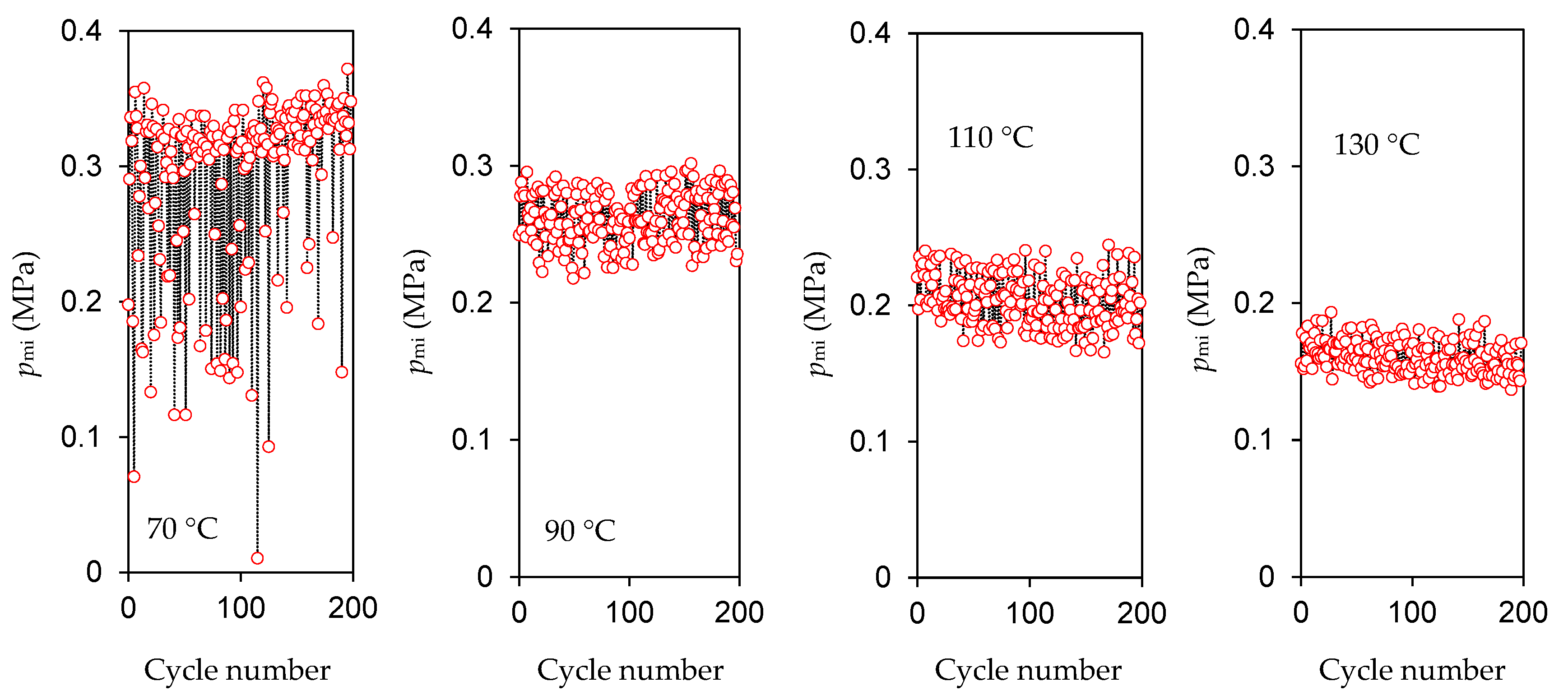
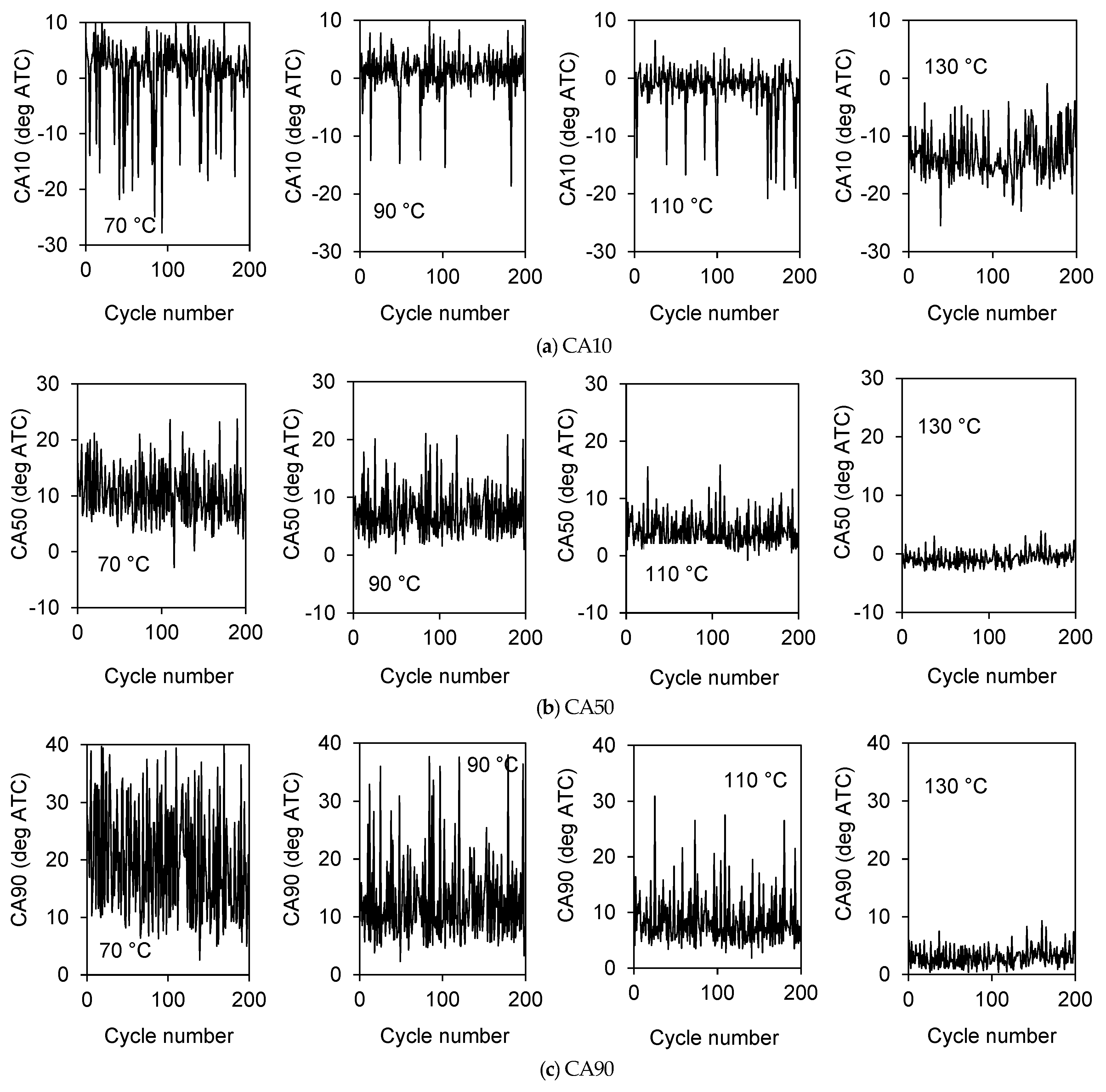
The combustion pressure and heat release rate curves averaged over 200 consecutive test cycles at the compression ratios of 12.4, 14.1, 16.5, 19.9, and 25.2 are given in Figure 3. The cylinder block temperature was controlled at 120 °C during the tests. In Figure 3a, the maximum combustion pressure (pmax) tends to increase, and the crank angle related to the maximum combustion pressure (Apmax) tends to advance as the compression ratio increases. When the compression ratio rises gradually from 14.1 to 19.9, pmax increases from 3.47 MPa to 5.47 MPa, and Apmax is moved from 10.3 deg after top center (ATC) to 1.3 deg ATC. In Figure 3b, the combustion duration is shortened, and the heat release time is advanced as the compression ratio gradually increases from 14.1 to 19.9. At the same time, a low-temperature exothermic reaction indicated by the bumps at the beginning of the heat release curves can be observed, which are advanced but weakened as the compression ratio increases. However, when the compression ratio rises to 25.2, the low-temperature exothermic reaction is no longer apparent; instead, an endothermic reaction with a negative heat release rate occurs. Meanwhile, the heat release time is delayed, and the heat release rate and cumulative heat release energy are reduced. Theoretically, the low-temperature exothermic reaction at the pre-combustion stage generates reactive atoms that help the primary heat release reaction in the combustion process. The inadequate low-temperature exothermic reaction can suppress the primary heat release reaction and may lead to abnormal in-cylinder combustion.
It is considered that the tendency of the low-temperature exothermic reaction in the pre-combustion stage to weaken with increasing compression ratio may be related to the pre-compression air–fuel mixture temperature. As can be seen, the combustion pressure and temperature at the end of the expansion stroke tend to decrease with the increasing compression ratio (see the in-cylinder pressure variation in Figure 3a), which indeed results in the temperature decrease of the residual exhaust gas in the cylinder and the tendency of the temperature of the pre-compression air–fuel mixture in the next cycle to decrease [28]. The decrease in the temperature of the pre-compression air–fuel mixture in the next cycle should lead to an insufficiently low-temperature exothermic reaction. When the compression ratio is increased to 25.2, abnormal combustion with many partial burning and misfire cycles occurs (see Figure 4 and Figure 5), which results in a drastic change in the chemical composition and thermal state of the residual exhaust gases in the cylinder. In this case, the low-temperature exothermic reaction does not proceed normally and presents as an abnormal heat absorbing reaction, contributing to a more severe abnormal combustion phenomenon. In addition, at the compression ratio of 12.4, the heat release rate curve is close to the horizontal line, and no evident heat release phenomenon can be observed. At too low compression ratios, the increment of internal energy converted from the compression work in the compression stroke is not enough to cause the spontaneous combustion of the air–fuel mixture.
Figure 4 shows the cyclic variations in pmi over 200 consecutive test cycles at compression ratios of 14.1, 16.5, 19.9, and 25.2. At the compression ratio of 14.1, pmi varies from 0.23 to 0.28 MPa with a mean value of 0.251 MPa, and the cyclic variation coefficient in pmi (COVpmi) is 3.39%. At a compression ratio 16.5, pmi ranges from 0.16 to 0.23 MPa with a mean value of 0.192 MPa, and COVpmi is 6.30%. At the compression ratio 19.9, pmi goes from 0.10 to 0.16 MPa with a mean value of 0.130 MPa, and COVpmi is 7.82%. At the compression ratio of 25.2, pmi varies from −0.01 to 0.10 MPa with a mean value of 0.036 MPa, and COVpmi is 58.6%; at this moment, misfire and partial burning cycles are present in large numbers (if pmi of an individual cycle is less than one-third of the average pmi of successively sampled test cycles, the individual cycle is considered a partial burning or misfire cycle [33]). As shown in the figure, pmi drops unexpectedly as the compression ratio increases. Thermodynamically, the optimal combustion phase should end the combustion exothermic process with an isovolumic heating process at the TDC. Correspondingly, the recommended value of Apmax is generally from 10 to 15 deg ATC for modern reciprocating piston internal combustion engines. As seen in Figure 3a, Apmax is within the recommended range only at the compression ratio 14.1. In contrast, the combustion phase is excessively advanced at the other compression ratios and significantly decreases thermal efficiency.
Figure 5 shows the cyclic variations in CA10, CA50, and CA90 over 200 consecutive test cycles for 14.1, 16.5, 19.9, and 25.2 compression ratios. CA10 is the crank angle at which 10% fuel heat has been released, CA50 is the crank angle at which 50% fuel heat has been released, and CA90 is the crank angle at which 90% fuel heat has been released. In Figure 5a, CA10 slightly advances as the compression ratio increases from 14.1 to 16.5 to 19.9; however, the cyclic variations in CA10 are more significant, reflecting the relative instability of the low-temperature exothermic reaction. At the compression ratio 25.2, because of the heat absorbing process with a negative exothermic rate in the pre-combustion stage, CA10 calculated from the thermodynamic zero-dimensional model is relatively reversed. In Figure 5b, CA50 varies from 2.5 to 11.5 deg ATC at the compression ratio of 14.1, from −1.6 to 6.5 deg ATC at the compression ratio of 16.5, and from −5 to −1.4 deg ATC at the compression ratio of 19.9. Only at the compression ratio 14.1 is CA50 close to the thermodynamically recommended value of a range from 5 to 10 deg ATC. At the compression ratio of 25.2, CA50 no longer continues to advance. In Figure 5c, CA90 moves ahead as the compression ratio increases from 14.1 to 16.5 to 19.9 but is no longer advanced at the compression ratio 25.2. At the compression ratio of 19.9, most test cycles have CA90 at a point before the TDC, which denotes a highly unreasonable heat release time. In addition, the combustion duration identified by the interval between CA10 and CA90 decreases dramatically from 23.5 deg CA at the compression ratio of 14.1 to 10.5 deg CA at the compression ratio of 19.9; meanwhile, the cyclic variations in CA50 and CA90 decrease obviously. However, the improvement in combustion duration and stability does not compensate for the harmful effects of the heat release time being too far ahead at the compression ratio 19.9.

3.2. Thermal State

The combustion pressure and heat release rate curves averaged over 200 consecutive test cycles at the cylinder block temperatures of 70, 90, 110, and 130 °C are given in Figure 6. The compression ratio was adjusted to 16.5 in the tests. In Figure 6a, as the cylinder block temperature increases from 70 to 130 °C, pmax rises from 4.16 to 4.85 MPa, and Apmax is advanced from 10.4 to 4.3 deg ATC. In Figure 6b, the heat release time is advanced, the combustion duration is shortened, and the peak heat release rate increases with increasing cylinder block temperature; meanwhile, the low-temperature exothermic reaction also becomes more intense but does not change in its onset time. Theoretically, temperature strongly affects the chemical kinetic reaction rate in the HCCI combustion process. Under micro-scale conditions, the area-to-volume ratio increases dramatically, and the influence of the thermal state on the in-cylinder combustion should be more sensitive. In this situation, heating the cylinder and crankcase walls of the fresh intake mixture becomes the dominant factor influencing the thermal state of the pre-compression air–fuel mixture. Consequently, the low-temperature exothermic reaction in the pre-combustion stage becomes more intense as the cylinder block temperature increases, significantly influencing the subsequent combustion process.
Figure 7 shows the cyclic variations in pmi over 200 consecutive test cycles for the cylinder block temperatures of 70, 90, 110, and 130 °C. At the cylinder block temperature of 70 °C, the excessively low cylinder temperature leads to abnormal combustion, and more misfire or partial burning cycles can be observed; pmi varies from 0.01 to 0.37 MPa with a mean value of 0.291 MPa. At the cylinder block temperature of 90 °C, pmi ranges from 0.22 to 0.30 MPa with a mean value of 0.262 MPa. At the cylinder block temperature of 110 °C, pmi varies from 0.16 to 0.25 MPa with a mean value of 0.203 MPa. At the cylinder block temperature of 130 °C, pmi ranges from 0.14 to 0.19 MPa with a mean value of 0.161 MPa. As the cylinder block temperature increases, combustion becomes more stable, and COVpmi decreases from 23.1% at 70 °C to 7.2% at 130 °C. Notably, pmi decreases significantly with increasing cylinder block temperature. On the one hand, a cylinder block temperature that is too high can lead to a too early heat release time and reduce thermal efficiency. On the other hand, high-temperature components heat intake gas and lower intake density, thus minimizing intake charge. The intake flow rate was measured to be 2.14 L/min at the cylinder block temperature of 70 °C, while it dropped to 1.96 L/min at 130 °C. The thermal state heavily influences the gas exchange process at the millimeter scale.
Figure 8 shows the cyclic variations in CA10, CA50, and CA90 over 200 consecutive test cycles for the cylinder block temperatures of 70, 90, 110, and 130 °C. CA10, CA50, and CA90 advance with increasing cylinder block temperature. At the cylinder block temperature of 130 °C, the advancement of CA10 is more pronounced, and CA50 moves forward to the point adjacent to the TDC; thus, the heat release time seriously deviates from the thermodynamically ideal value. The unreasonable heat release time leads to a reduction in thermal efficiency. In addition, the cyclic variations in CA10, CA50, and CA90 tend to decrease with increasing cylinder block temperature. This trend is relatively more prominent for CA50 and CA90, where the variation range of CA50 shrinks from −2.8 to 23.7 deg ATC at 70 °C to from −3.1 to 3.9 deg ATC at 130 °C, and that of CA90 shrinks from 2.7 to 39.7 deg ATC at 70 °C to from 0.4 to 9.3 deg ATC at 130 °C. Combustion stability can be improved with higher cylinder block temperatures at the millimeter scale.

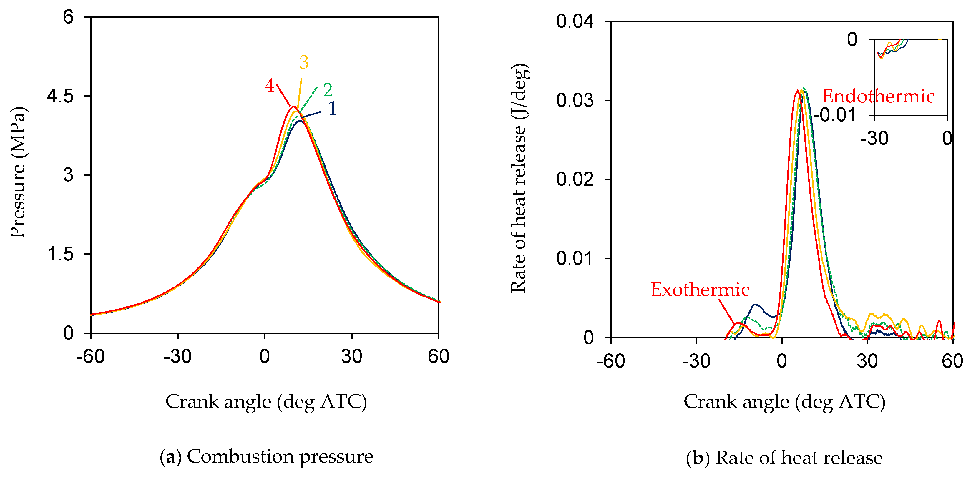
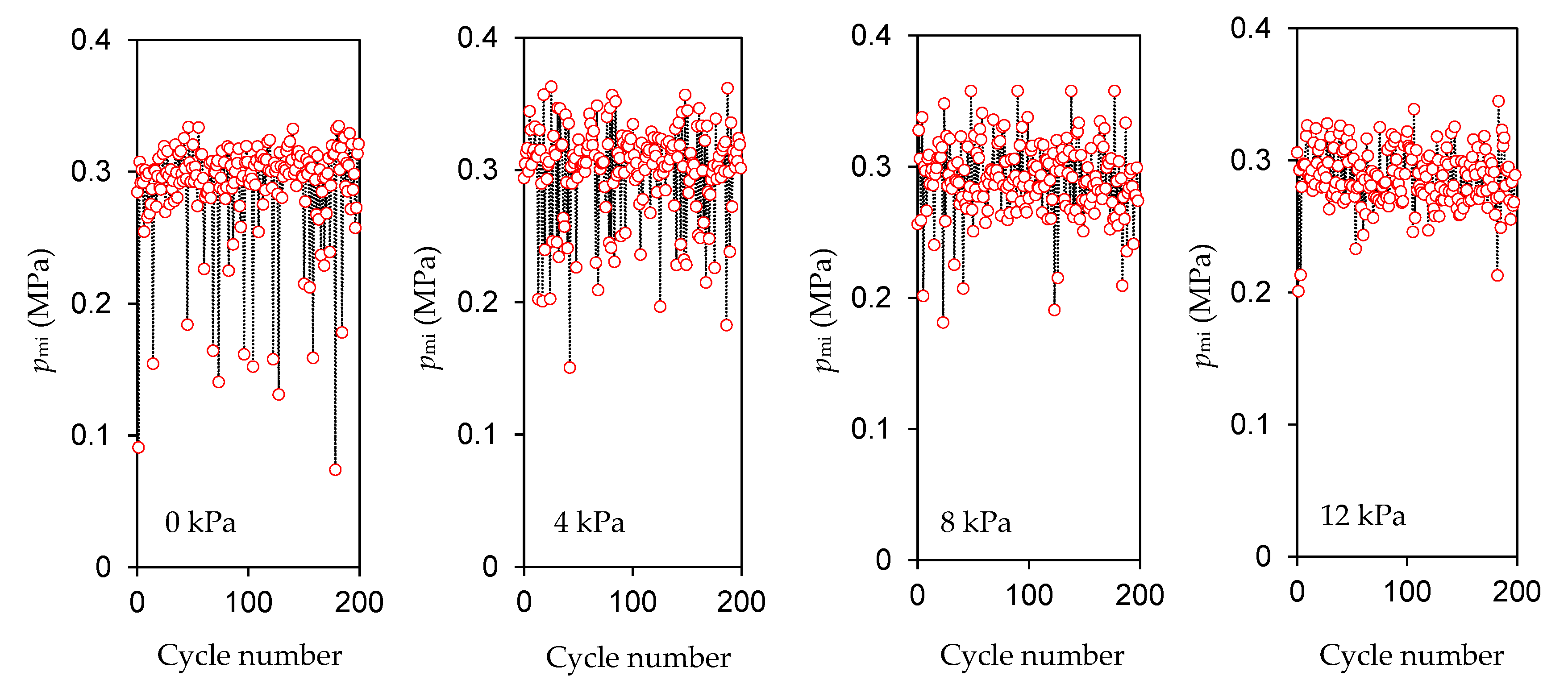
3.3. Intake Pressure

Boosting the intake pressure can improve the cross-scavenged gas exchange process, helping to reduce the amount of residual exhaust gas in the cylinder and increase the intake charge. The combustion pressures and heat release rate curves averaged over 200 consecutive test cycles for the intake pressures (gauge pressure) of 0, 4, 8, and 12 kPa are given in Figure 9. The compression ratio was adjusted to 16.5, and the cylinder block temperature was controlled at 80 °C in the tests. In Figure 9a, pmax increases from 4.03 MPa to 4.31 MPa, and Apmax is advanced from 12.1 deg ATC to 10.1 deg ATC as the intake pressure gradually increases from 0 kPa to 12 kPa. In Figure 9b, the low-temperature exothermic reaction time and the heat release time are advanced with increasing intake pressure, but the low-temperature exothermic reaction becomes weaker. This phenomenon is similar to that presented when the compression ratio is increased and demonstrates the closer correlation between the low-temperature exothermic reaction in the pre-combustion stage and the in-cylinder residual exhaust gases. As the intake pressure rises, the fresh intake charge can push more exhaust gas out of the cylinder during the cross-scavenged gas exchange process so that the amount of high-temperature residual exhaust gas in the cylinder will decrease. In the next cycle, the temperature of the pre-compressed air–fuel mixture that is mixed by the fresh intake charge and the residual exhaust gases in the cylinder will be reduced, making the low-temperature combustion reaction weaker. However, the reduction in residual exhaust gas also benefits the subsequent primary combustion process, resulting in an earlier combustion time and improved combustion stability.
Figure 10 shows the cyclic variations in pmi over 200 consecutive test cycles for the intake pressures of 0, 4, 8, and 12 kPa. As the figure shows, the combustion stability can be improved with increasing intake pressure, and COVpmi decreases from 14.7% at 0 kPa to 7.7% at 12 kPa. The reduction in residual exhaust gas in the cylinder can explain the improvement in combustion stability. However, pmi does not change much, and its mean value remains around 0.3 MPa at the different intake pressures. The effect of intake pressure on in-cylinder combustion is less pronounced than that of compression ratio and cylinder block temperature.
Figure 11 illustrates the trend of pmi with CA50 over 200 consecutive test cycles for the cylinder block temperatures of 80, 100, and 120 °C and different intake pressures of 4, 8, and 12 kPa. As seen, boosting intake pressure affects in-cylinder combustion differently at different cylinder block temperatures. In Figure 11a, the cylinder block temperature is 80 °C. At the intake pressure of 4 kPa, many test cycles burn late with CA50 later than 20 deg ATC, present low pmi, and partially exhibit misfire or partial burning. When the intake pressure is increased to 12 kPa, the number of test cycles with CA50 later than 20 deg ATC decreases, and combustion stability is improved. Notably, the increase in intake pressure does not contribute significantly to the rise in pmi. In Figure 11b, the cylinder block temperature is 100 °C. Boosting the intake pressure slightly affects combustion stability but does not result in a noticeable rise in pmi. In Figure 11c, the cylinder block temperature is 120 °C. As the intake pressure increases from 4 to 12 kPa, combustion stability is little affected, but pmi rises from 0.205 to 0.249 MPa on average. In addition, CA50 advances with increasing intake pressure. At the intake pressure of 12 kPa, pmi increases with the delayed CA50, which indicates the combustion phase is too early and deviates from the thermodynamically optimal value. In Figure 11c, the increase in pmi benefits from improved gas exchange rather than in-cylinder combustion. When the intake pressure is increased from 0 kPa to 12 kPa, the measured intake flow rate increases from 1.98 L/min to 2.23 L/min.
Even though pmi shows a visible increase with increasing intake pressure at the cylinder block temperature of 120 °C, the maximum pmi is still obviously lower than that at the cylinder block temperature of 80 °C. For the gas exchange process using the cross-scavenged mode, increasing the intake flow by boosting the intake pressure is impractical because in-cylinder pressure at the end of the scavenging process is determined more by exhaust pressure than by intake pressure. At the cylinder block temperature of 80 °C, the intake and exhaust flow rates are also more extensive than those at the cylinder block temperature of 120 °C, resulting in a higher exhaust back pressure observed in the pressure curves in Figure 6a. So, the effect of boosting the intake pressure on the gas exchange is relatively small compared to that at the cylinder block temperature of 120 °C. At the cylinder block temperature of 80 °C, the intake flow rate was measured to increase from 2.19 L/min to 2.30 L/min as the intake pressure increased from 0 to 12 kPa. The increment is lower than that at the cylinder block temperature of 120 °C. Therefore, improving the operating load to compensate for increased friction, blow-by, and heat transfer losses remains challenging for downsizing reciprocating piston internal combustion engines.

4. Conclusions

The millimeter-scale HCCI reciprocating piston internal combustion engine fueled by a mixture of kerosene, ether, castor oil, and isopropyl nitrate was used to complete the combustion investigation. Despite the lack of the mandatory control for in-cylinder ignition and combustion behavior under the micro space constraints, the millimeter-scale HCCI reciprocating piston internal combustion engine achieved excellent stable combustion adapted to the thermodynamic cycle of the reciprocating piston internal combustion engine by adjusting the compression ratio and thermal state which sensitively affect the in-cylinder combustion at the millimeter scale.
Stable combustion occurs at 14.1, 16.5, and 19.9 compression ratios. With the increasing compression ratio, pmax increases, the combustion duration is shortened, the heat release time is advanced, and COVpmi increases slightly. Still, the intensity of the low-temperature exothermic reaction in the pre-combustion stage decreases. When the compression ratio rises to 25.2, the low-temperature exothermic reaction is no longer apparent and is substituted by an obvious endothermic reaction, accompanied by many partial burning and misfire cycles. At the compression ratio of 14.1, the heat release time is best for the thermodynamic cycle of reciprocating piston internal combustion engines, with pmi showing a maximum value.
As the cylinder block temperature gradually increases from 70 to 130 °C, the heat release time is advanced, the combustion duration is shortened, COVpmi decreases, and the low-temperature exothermic reaction becomes more intense. However, pmi decreases significantly with the increasing cylinder block temperature. The high cylinder block temperature leads to the heat release time being too early, and the high-temperature components heat the intake gas, lower the intake density, and thus reduce the intake charge. The thermal state significantly influences the millimeter-scale in-cylinder combustion and gas exchange processes.
Boosting intake pressure helps to improve the gas exchange process and reduce the amount of residual exhaust gas, thus accelerating exothermic combustion and improving combustion stability. However, this effect of intake pressure on in-cylinder combustion is less noticeable than that of the compression ratio and cylinder block temperature. Increasing the intake charge by raising the intake pressure is impractical in the cross-scavenged gas exchange mode, and the resulting increase in pmi is not evident. How to intensify the operating load to compensate for the increase in friction, blow-by, and heat transfer losses at the micro scale remains an open question.
At the compression ratio of 14.1, cylinder block temperature of 120 °C, and engine speed of 6000 r/min, the statistics for 200 consecutive sampling test cycles are 3.47 MPa for pmax, 10.3 deg ATC for Apmax, 6.53 deg ATC for CA50, 23.5 deg CA for the combustion duration, and 3.39% for COVpmi, indicating excellent in-cylinder combustion that is not inferior to that of the conventional-sized reciprocating piston internal combustion engine. The HCCI combustion mode has been verified to be feasible at the millimeter scale, and it should be an ideal micro-scale combustion solution for further downsizing reciprocating piston internal combustion engines.

Author Contributions

Conceptualization, L.Z.; methodology, H.S. and Z.T.; software, H.S.; validation, H.S. and L.Z.; formal analysis, H.S. and Z.T.; investigation, Z.T. and T.Z.; resources, L.Z. and Y.W.; data curation, H.S. and Z.T.; writing—original draft preparation, H.S. and J.H.; writing—review and editing, L.Z. and J.H.; visualization, H.S.; supervision, L.Z.; project administration, Y.W.; funding acquisition, L.Z. All authors have read and agreed to the published version of the manuscript.

Funding

This research was supported by the National Natural Science Foundation of China (Grant Number: 51175530), the Fundamental Research Funds for the Central Universities (Grant Number:2022CDJDX–004), and the Science and Technology Research Project of Henan Province (Grant Number: 202102210204).

Institutional Review Board Statement

Not applicable.

Informed Consent Statement

Not applicable.

Data Availability Statement

The data presented in this study are available on request from the corresponding author.

Conflicts of Interest

The authors declare no conflicts of interest.

References

  1. Ju, Y.; Maruta, K. Microscale combustion: Technology development and fundamental research. Prog. Energy Combust. Sci. 2011, 37, 669–715. [Google Scholar] [CrossRef]
  2. Wan, J.; Fan, A. Recent progress in flame stabilization technologies for combustion-based micro energy and power systems. Fuel 2021, 286, 119391. [Google Scholar] [CrossRef]
  3. Mahmud, M.A.P.; Bazaz, S.R.; Dabiri, S.; Mehrizi, A.A.; Asadnia, M.; Warkiani, M.E.; Wang, Z.L. Advances in MEMS and microfluidics-based energy harvesting technologies. Adv. Mater. Technol. 2022, 7, 2101347. [Google Scholar] [CrossRef]
  4. Chen, W.L.; Currao, G.; Li, Y.H.; Kao, C.C. Employing Taguchi method to optimize the performance of a microscale combined heat and power system with Stirling engine and thermophotovoltaic array. Energy 2023, 270, 126897. [Google Scholar] [CrossRef]
  5. E, J.Q.; Ding, J.J.; Chen, J.W.; Liao, G.L.; Zhang, F.; Luo, B. Process in micro-combustion and energy conversion of micro power system: A review. Energy Convers. Manag. 2021, 246, 114664. [Google Scholar]
  6. Velidi, G.; Yoo, C.S. A Review on flame stabilization technologies for UAV engine micro-meso scale combustors: Progress and challenges. Energies 2023, 16, 3968. [Google Scholar] [CrossRef]
  7. Formosa, F.; Frechette, L.G. Scaling laws for free piston Stirling engine design: Benefits and challenges of miniaturization. Energy 2013, 57, 796–808. [Google Scholar] [CrossRef]
  8. Dessornes, O.; Landais, S.; Valle, R.; Fourmaux, A.; Burguburu, S.; Zwyssig, C.; Kozanecki, Z. Advances in the Development of a Microturbine Engine. J. Eng. Gas Turbines Power 2014, 136, 071201. [Google Scholar] [CrossRef]
  9. Wang, W.; Zuo, Z.; Liu, J. Miniaturization limitations of rotary internal combustion engines. Energy Convers. Manag. 2016, 112, 101–114. [Google Scholar] [CrossRef]
  10. Shi, B.; Yu, H.; Zhang, J. The effects of the various factors and the engine size on micro internal combustion swing engine (MICSE). Appl. Therm. Eng. 2018, 144, 262–268. [Google Scholar] [CrossRef]
  11. Lungu, C.; Disseau, M.; Stubbs, D.; Jagoda, J.; Scarborough, D.E. An experimental and theoretical investigation of a small, high aspect-ratio, free-piston, two-stroke engine. Propuls. Power Res. 2020, 9, 326–343. [Google Scholar] [CrossRef]
  12. Maimani, F.; Calderon, A.A.; Yang, X.F.; Rigo, A.; Ge, J.Z.; Perez-Arancibia, N.O. A 7-mg miniature catalytic-combustion engine for millimeter-scale robotic actuation. Sens. Actuators A Phys. 2022, 341, 112818. [Google Scholar] [CrossRef]
  13. Lurie, E.; Kribus, A. Analysis of a Microscale ‘Saturation Phase-Change Internal Carnot Engine’. Energy Convers. Manag. 2010, 51, 1202–1209. [Google Scholar] [CrossRef]
  14. Amnache, A.; Liamini, M.; Gauthier, F.; Beauchesne-Martel, P.; Omri, M.; Fréchette, L.G. A MEMS turbopump for high temperature rankine micro heat engines—Part I: Design and fabrication. J. Microelectromech. Syst. 2020, 29, 1278–1292. [Google Scholar] [CrossRef]
  15. Blantin, J.R.; Polanka, M.D.; Ausserer, J.K.; Baranski, J.A. Correlations for the performance, efficiency, and energy losses for single cylinder, four-cycle internal combustion engines with displaced volumes ranging from 40 to 200 cc. J. Eng. Gas Turbines Power 2023, 145, 031027. [Google Scholar] [CrossRef]
  16. Raviteja, S.; Ramakrishna, P.A.; Ramesh, A. Performance enhancement of a small two-stroke engine using nitromethane blends. J. Propuls. Power 2019, 35, 520–529. [Google Scholar] [CrossRef]
  17. Rowton, A.K.; Ausserer, J.K.; Grinstead, K.D.; Litke, P.J.; Polanka, M.D. Measuring Scaling Effects in Small Two-Stroke Internal Combustion Engines. In Proceedings of the SAE/JSAE 2014 Small Engine Technology Conference & Exhibition, Pisa, Italy, 18–20 November 2014; SAE Technical Paper 2014-32-0010. SAE International: Warrendale, PA, USA, 2014. [Google Scholar]
  18. Tang, G.Z.; Wang, S.B.; Zhang, L.; Shang, H.C. Diagnosis and improvement of combustion characteristics of methanol miniature reciprocating piston internal combustion engine. Micromachines 2020, 11, 96. [Google Scholar] [CrossRef] [PubMed]
  19. Menon, S.; Cadou, C.P. Scaling of miniature piston-engine performance, part 1: Overall engine performance. J. Propuls. Power 2013, 29, 774–787. [Google Scholar] [CrossRef]
  20. Menon, S.; Cadou, C.P. Scaling of miniature piston engine performance, Part 2: Energy losses. J. Propuls. Power 2013, 29, 788–799. [Google Scholar] [CrossRef]
  21. Raine, R.R.; Thorwarth, H. Performance and Combustion Characteristics of a Glow-Ignition Two-Stroke Engine. In Proceedings of the SAE 2004 World Congress & Exhibition, Detroit, MI, USA, 8–11 March 2004; SAE Technical Paper 2004-01-1407. SAE International: Warrendale, PA, USA, 2004. [Google Scholar]
  22. Collair, K.; Floweday, G. Understanding HCCI Characteristics in Mini HCCI Engines. In Proceedings of the 2008 SAE International Powertrains, Fuels and Lubricants Congress, Shanghai, China, 23–25 June 2008; SAE Technical Paper 2008-1-1662. SAE International: Warrendale, PA, USA, 2008. [Google Scholar]
  23. Manente, V.; Tunestal, P.; Johansson, B. Influence of the Compression Ratio on the Performance and Emissions of a Mini HCCI Engine Fueled with Diethyl Ether. In Proceedings of the Powertrain & Fluid Systems Conference and Exhibition, Rosemont, IL, USA, 29–31 October 2007; SAE Technical Paper 2007-01-4075. SAE International: Warrendale, PA, USA, 2007. [Google Scholar]
  24. Manente, V.; Tunestal, P.; Johansson, B. Influence of the Wall Temperature and Combustion Chamber Geometry on the Performance and Emissions of a Mini HCCI Engine Fueled with Diethyl Ether. In Proceedings of the SAE World Congress & Exhibition, Detroit, MI, USA, 14–17 April 2008; SAE Technical Paper 2008-01-0008. SAE International: Warrendale, PA, USA, 2008. [Google Scholar]
  25. Tian, L. Experimental tests and simulations of a 1.5cc miniature glow-ignition two-stroke engine. In Proceedings of the SAE World Congress & Exhibition, Detroit, MI, USA, 13–15 April 2010; SAE Technical Paper 2010-32-0018. SAE International: Warrendale, PA, USA, 2010. [Google Scholar]
  26. Shang, H.; Zhang, L.; Tang, Z.; Du, B.; Chen, X. Adjusting mixture composition of alcohol-based fuels for improving combustion in a 0.99 cc miniature IC engine. Chem. Eng. Process.-Process Intensif. 2020, 153, 107988. [Google Scholar] [CrossRef]
  27. Zhang, L.; Zeng, X.R.; Shang, H.C.; Tang, Z.G.; Geng, Y.T.; Han, J.L. Experimental investigation about effect of glow intensity on combustion characteristics for a micro IC engine with platinum wire glow-ignition. Appl. Therm. Eng. 2016, 109, 196–206. [Google Scholar] [CrossRef]
  28. Shang, H.C.; Zhang, L.; Tang, Z.G.; Chen, X. Experiment on the influence of residual exhaust gas on the combustion characteristics of a miniature engine with platinum wire ignition. ACS Omega 2022, 7, 7393–7402. [Google Scholar] [CrossRef] [PubMed]
  29. Therkelsen, P.; Dunn-Rankin, D. Small-Scale HCCI Engine Operation. Combust. Sci. Technol. 2011, 183, 928–946. [Google Scholar] [CrossRef]
  30. Sher, I.; Levinzon-Sher, D.; Sher, E. Miniaturization limitations of HCCI internal combustion engines. Appl. Therm. Eng. 2009, 29, 400–411. [Google Scholar] [CrossRef]
  31. Wu, Y.Y.; Chen, B.C.; Tsai, H.C.; Liu, T.C. The possibility of running homogeneous charge compression ignition in spark ignition and compression ignition small-scale engines. Proc. Inst. Mech. Eng. Part A J. Power Energy 2011, 225, 579–590. [Google Scholar] [CrossRef]
  32. Shang, H.C.; Zhang, L.; Chen, B.; Chen, X. Experimental test and thermodynamic analysis on scaling-down limitations of a reciprocating internal combustion engine. Sci. Prog. 2020, 103, 0036850420935731. [Google Scholar] [CrossRef] [PubMed]
  33. Heywood, J.B. Internal Combustion Engine Fundamentals, 1st ed.; McGraw-Hill: New York, NY, USA, 1988. [Google Scholar]
Figure 1. Test bench: 1—frequency converter; 2—digital multimeter; 3—micro-flow meter; 4—toothed disc; 5—high-speed motor; 6—hysteresis brake; 7—dial indicator; 8—test engine; 9—fuel weighing equipment; 10—fuel tank; 11—crank angle sensor; 12—pressure sensor; 13—data acquisition module; 14—data monitor and analysis.
Applsci 14 07359 g001
Figure 2. Pressure sensor mounting and compression ratio adjusting.
Applsci 14 07359 g002
Figure 3. Combustion pressures and heat release rates at different compression ratios: 1—CR 12.4 (purple); 2—CR 14.1 (black); 3—CR 16.5 (green); 4—CR 19.9 (yellow); 5—CR 25.2 (red).
Applsci 14 07359 g003
Figure 4. pmi at different compression ratios.
Applsci 14 07359 g004
Figure 5. CA10, CA50, and CA90 at different compression ratios.
Applsci 14 07359 g005
Figure 6. Combustion pressures and heat release rates at different cylinder block temperatures: 1—70 °C (black); 2—90 °C (green); 3—110 °C (yellow); 4—130 °C (red).
Applsci 14 07359 g006
Figure 7. pmi at different cylinder block temperatures.
Applsci 14 07359 g007
Figure 8. CA10, CA50, and CA90 at different cylinder temperatures.
Applsci 14 07359 g008
Figure 9. Combustion pressures and heat release rates at different intake pressures (under the cylinder block temperature of 80 °C): 1—0 kPa (black); 2—4 kPa (green); 3—8 kPa (yellow); 4—12 kPa (red).
Applsci 14 07359 g009
Figure 10. pmi at different intake pressures (under cylinder block temperature of 80 °C).
Applsci 14 07359 g010
Figure 11. Relationship between pmi and CA50 at different intake pressures and cylinder block temperatures.
Applsci 14 07359 g011
Table 1. Technical data of the measuring instruments.
NameMakerTypeMeasurement RangeAccuracy
Pressure transducerKISTLER Ltd.6052B0–25 MPa≤±0.3%/FSO
Crank angle sensor ONO SOKKIMP-9350–360 deg CA≤±0.1 deg CA
K-type thermocoupleVICTOR Technology DM6801A−50–1300 °C≤±0.4 °C
Photoelectric tachometerSUWEI Electronic TechnologyDT2234B3–99,999 r/min≤±1 r/min
Flow meterSIARGOMF5706-N-250–25 L/min≤2.5%
Dial indicatorHENGLIANG Measuring Tools
(Zhengzhou, China)
A-331–10 mm≤±0.01 mm
Fuel weighing balanceYOUHENG Weighing Equipment
(Hangzhou, China)
BS600L0–600 g≤±0.15 g
Table 2. Properties of fuel components.
TypeKeroseneDiethyl EtherCastor OilIsopropyl Nitrate
Chemical formulaC12H26C4H10OC18H34O3C3H7NO3
Heat value (MJ/kg)41.833.937.2-
Hexadecane value41.4>125-1200
Ignition temperature (°C)210160--
Table 3. Combustion chamber volume and compression ratio with the displacement of the adjustment nut.
Number of TurnsMovement Distance (mm)Combustion Chamber Volume (mm3)Compression Ratio (-)
0/809.8856.4
1/80.116.2434.7
2/80.222.6125.2
3/80.328.9719.9
4/80.435.3316.5
5/80.541.6914.1
6/80.648.0512.4
Disclaimer/Publisher’s Note: The statements, opinions and data contained in all publications are solely those of the individual author(s) and contributor(s) and not of MDPI and/or the editor(s). MDPI and/or the editor(s) disclaim responsibility for any injury to people or property resulting from any ideas, methods, instructions or products referred to in the content.

