
Considerations Regarding Sandblasting of Ti and Ti6Al4V Used in Dental Implants and Abutments as a Preconditioning Stage for Restorative Dentistry Works


 and
and
Abstract
Featured Application
Abstract
1. Introduction
2. Materials and Methods
- -
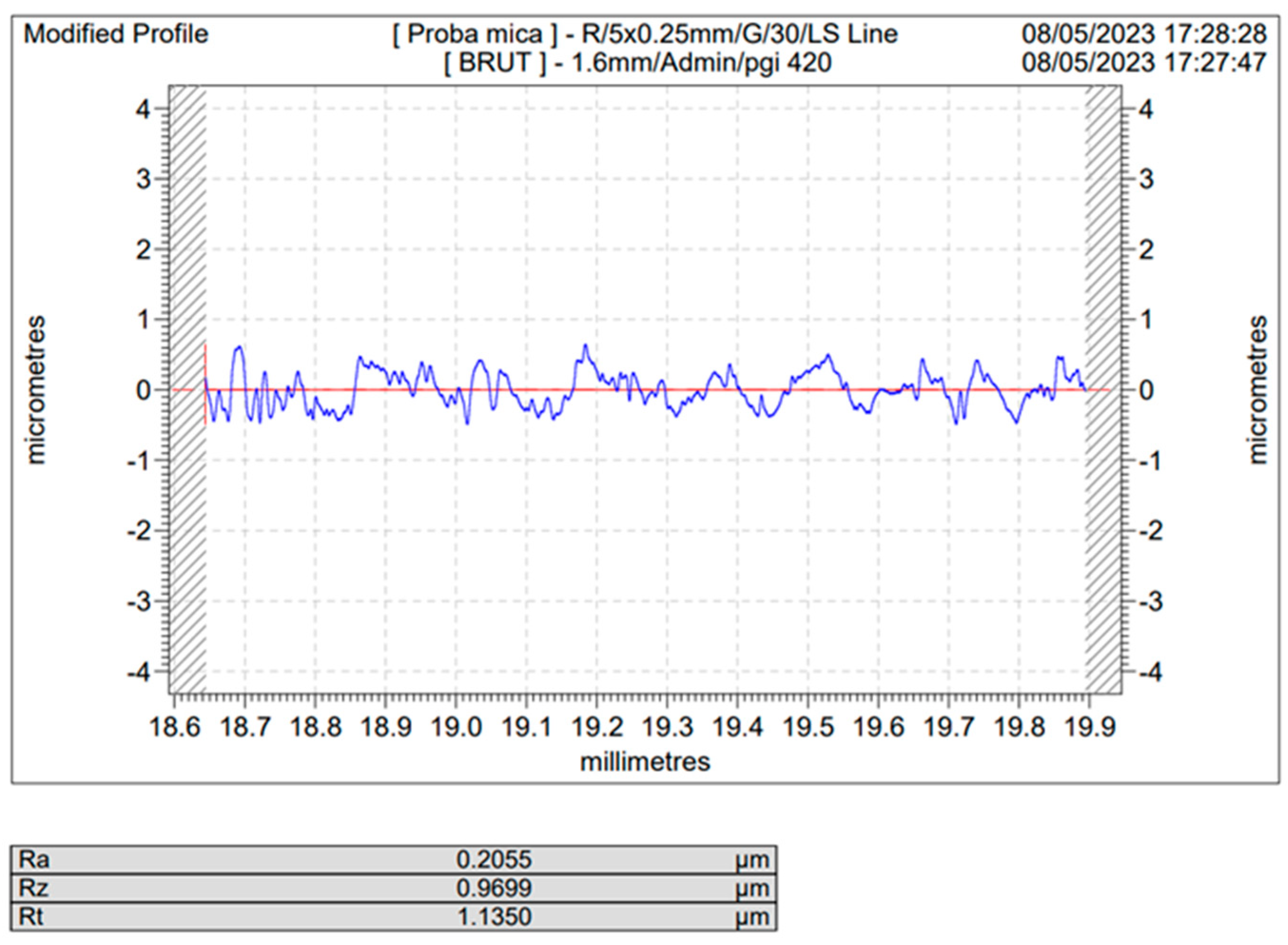
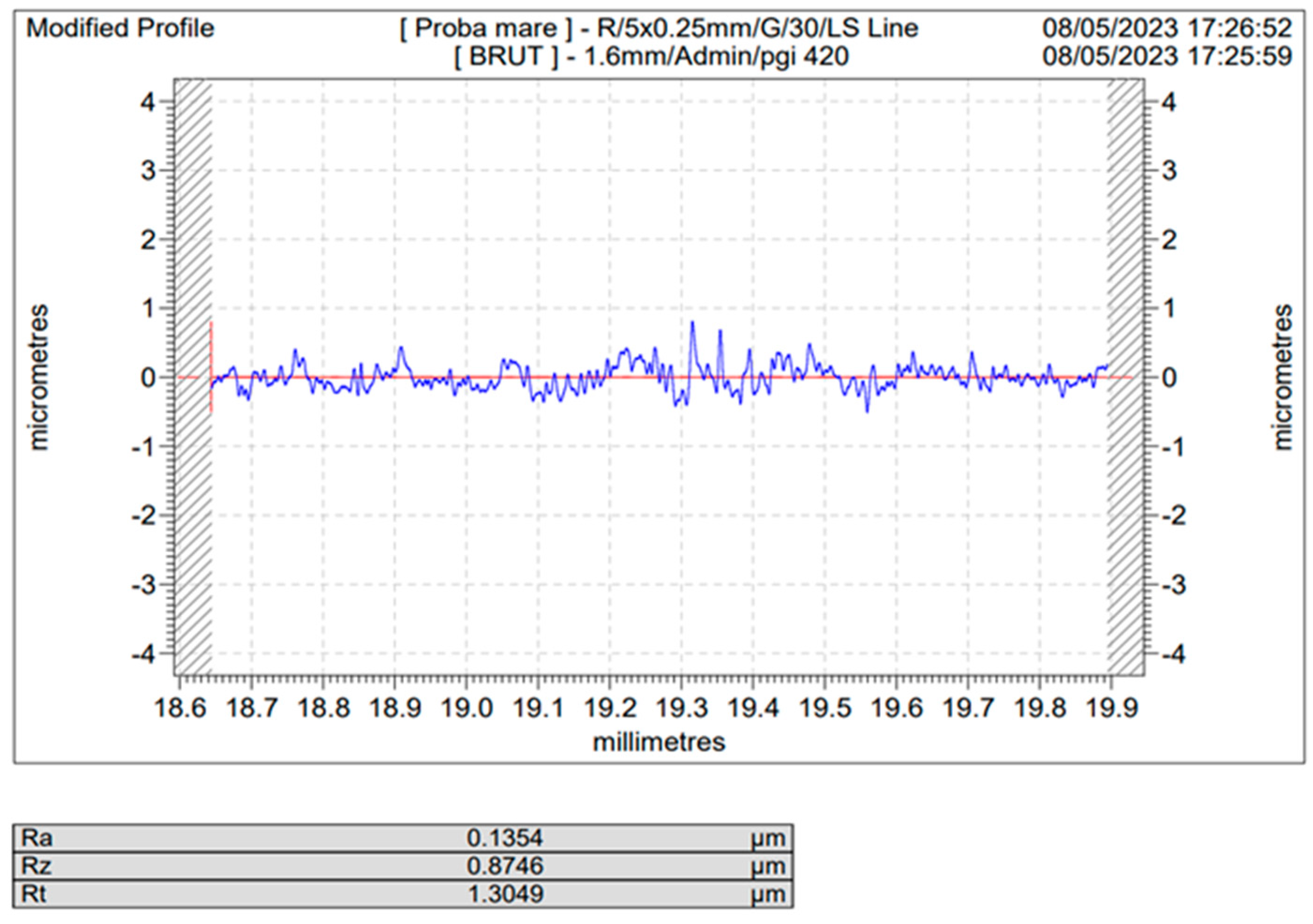
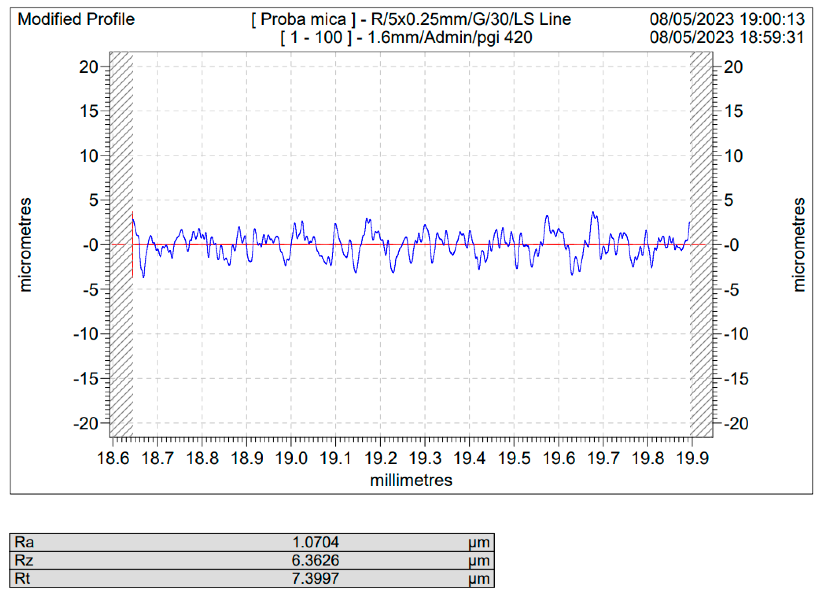
- The Ra parameter evaluates the average of the peaks and valleys on the scanned surface within the evaluation length;
- -
- The Rz parameter evaluates the average height between the five highest peaks, as well as the average depth between the five lowest valleys, on the scanned surface;
- -
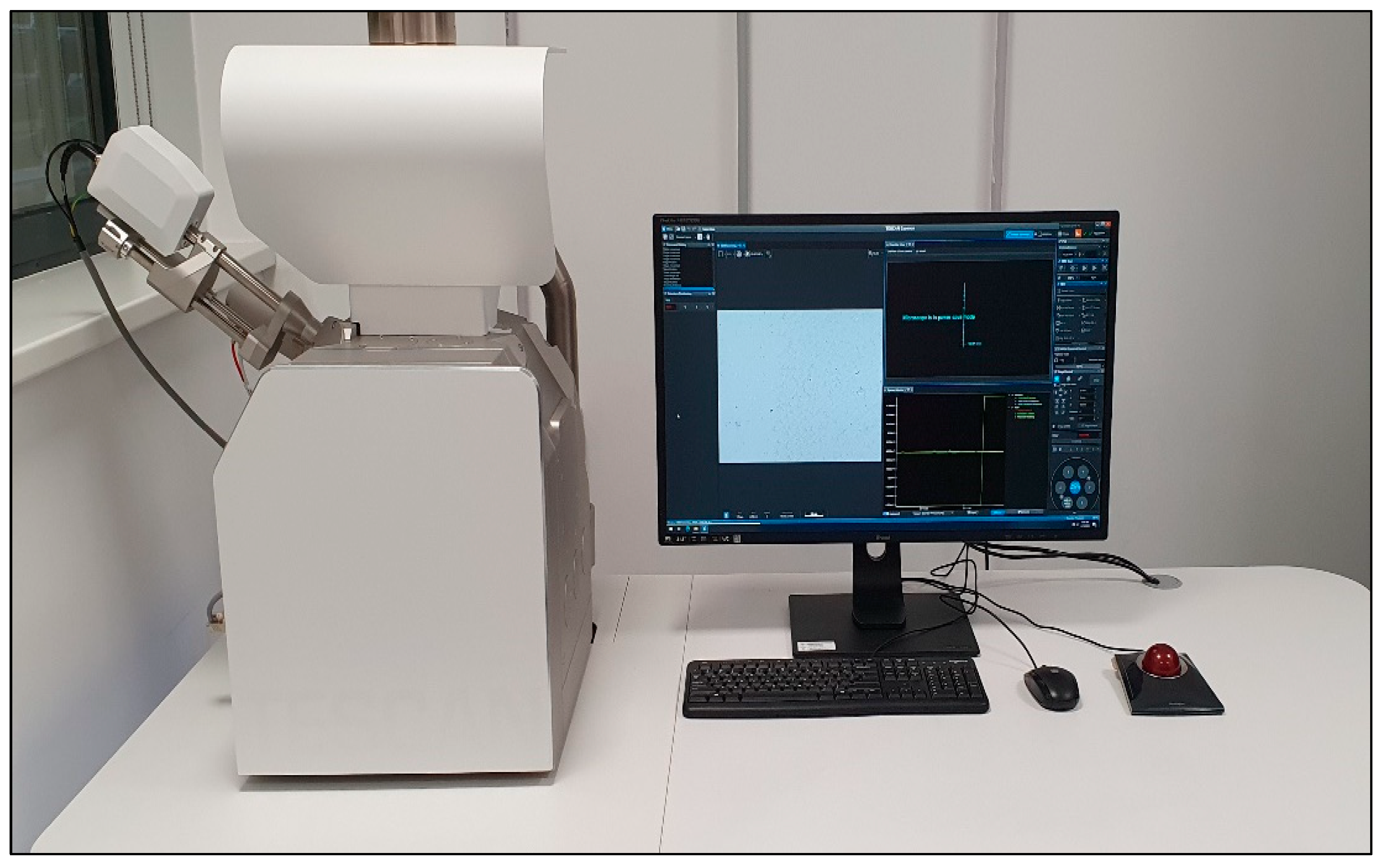
- The Rt parameter evaluates the difference between the height of the highest peak and the depth of the deepest valley within the evaluation length. To determine the surface roughness of the samples and the differences between the processes to which they were subjected, the Hommel-Etamic Nanoscan 855 Jenoptik, Vienna, Austria equipment presented in Figure 1 was used. The Hommel-Etamic Nanoscan 855 has a resolution of 0.6 nanometers on a 20 mm measuring range.
3. Results
3.1. Determination of the Roughness Profile and the Parameters of the Blasted Samples
- White electrocorundum F90 of particle size 0.15–0.20 mm mixed with sintered hydroxyapatite 3:1, normal working pressure, 6 bar;
- White electrocorundum F90 of particle size 0.15–0.20 mm mixed with sintered hydroxyapatite 3:1, half working pressure, 3 bar;
- White electrocorundum of particle size 0.10–0.15 mm mixed with sintered hydroxyapatite, 3:1, normal working pressure, 6 bar;
- White electrocorundum of particle size 0.10–0.15 mm mixed with sintered hydroxyapatite, 3:1, half working pressure, 3 bar;
- White electrocorundum F90 particle size 0.15–0.20 mm—normal working pressure, 6 bar;
- White electrocorundum F90 particle size 0.15–0.20 mm—half working pressure, 3 bar;
- White electrocorundum of 0.10–0.15 mm particle size—normal working pressure, 6 bar;
- White electrocorundum of 0.10–0.15 mm particle size—half working pressure, 3 bar rate;
- Glass balls for sandblasting 0.04–0.07 mm—normal working pressure, 6 bar;
- Glass balls for sandblasting 0.04–0.07 mm—half working pressure, 3 bar;
- Olivine—particle size 0.1–0.5 mm—normal working pressure, 6 bar;
- Olivine—particle size 0.1–0.5 mm—half working pressure, 3 bar;
- Red garnet—particle size 0.40–0.80 mm—normal working pressure, 6 bar;
- Red garnet—particle size 0.40–0.80 mm—half working pressure, 3 bar;
- Brown electrocorundum—particle size 0.120–0.212 mm—normal working pressure, 6 bar;
- Brown electrocorundum—particle size 0.120–0.212 mm—half working pressure, 3 bar.
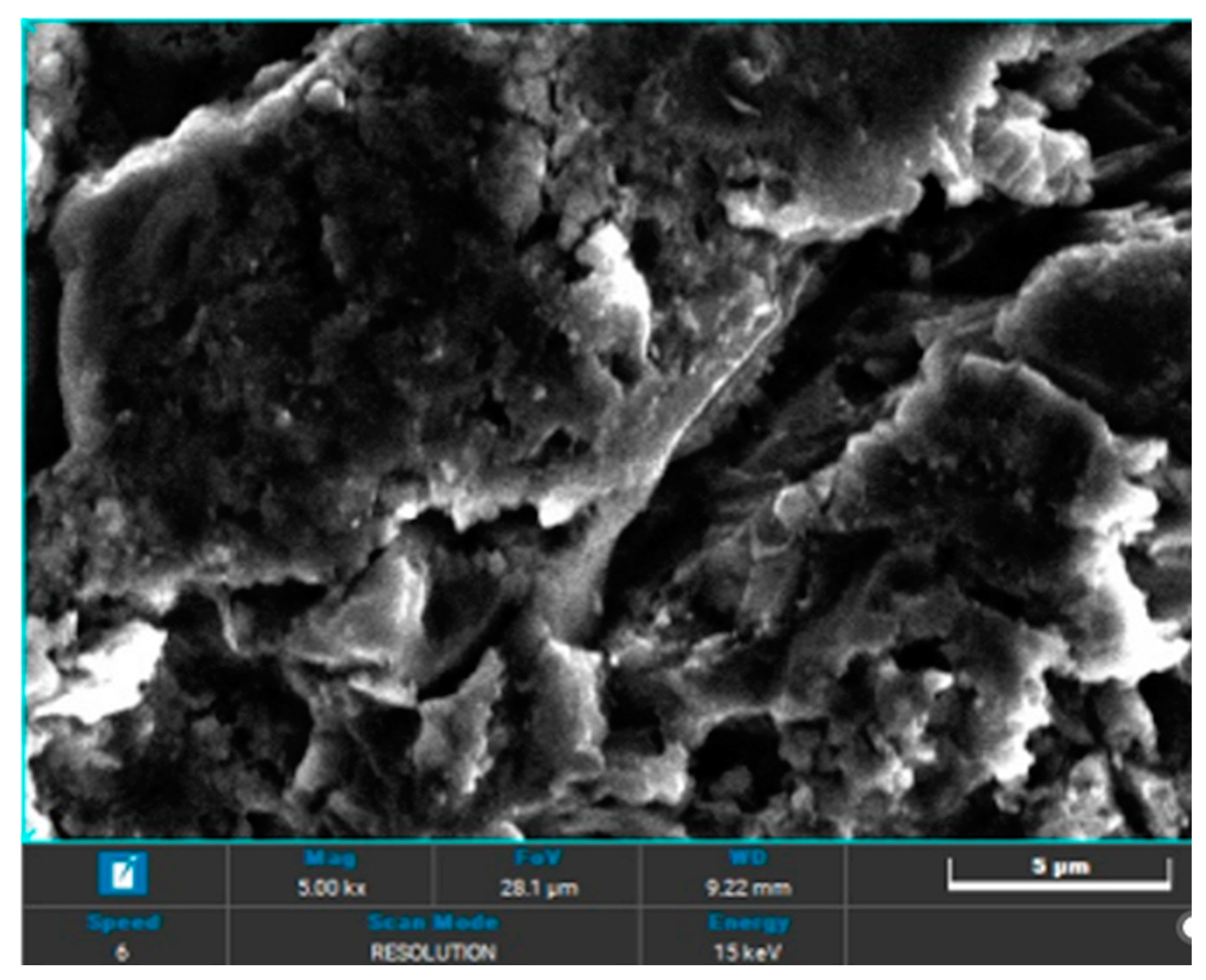
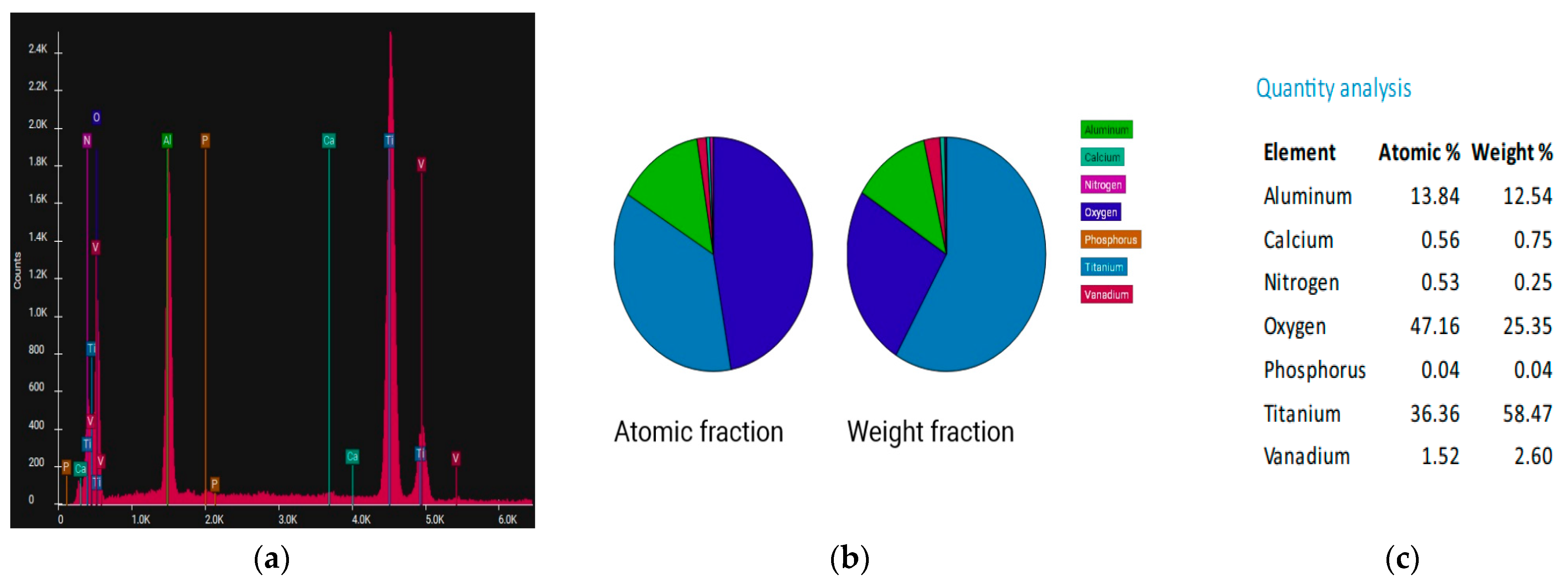
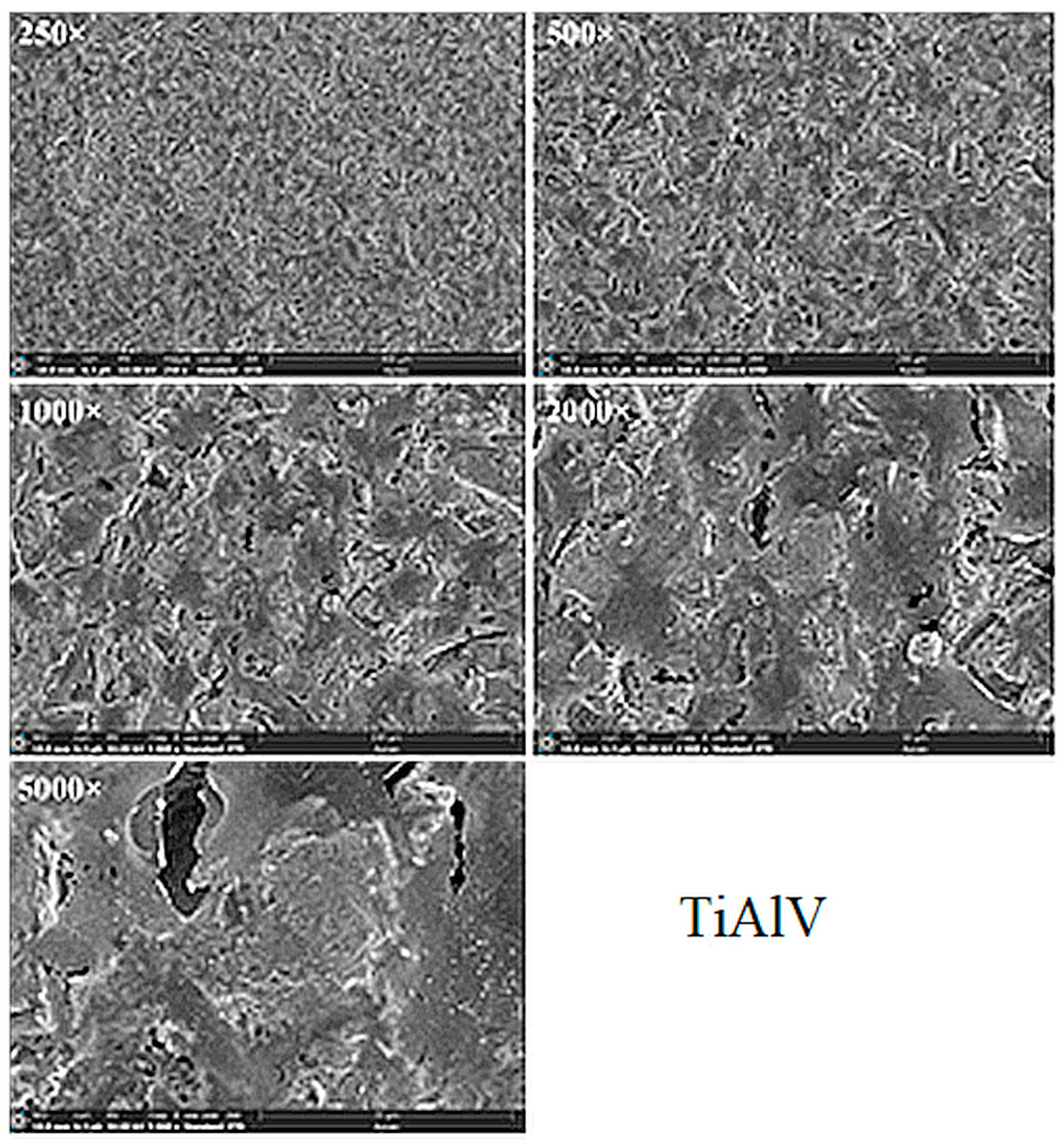
3.2. SEM Analysis
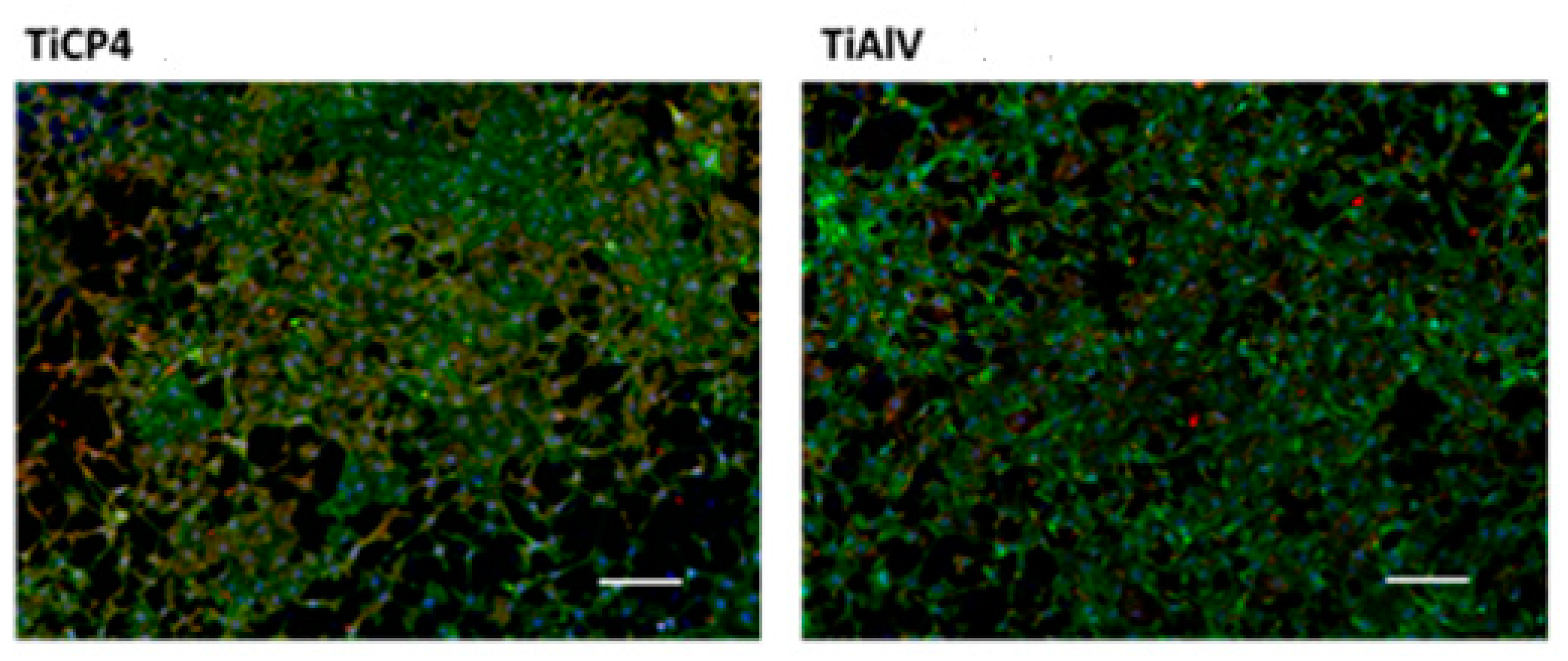
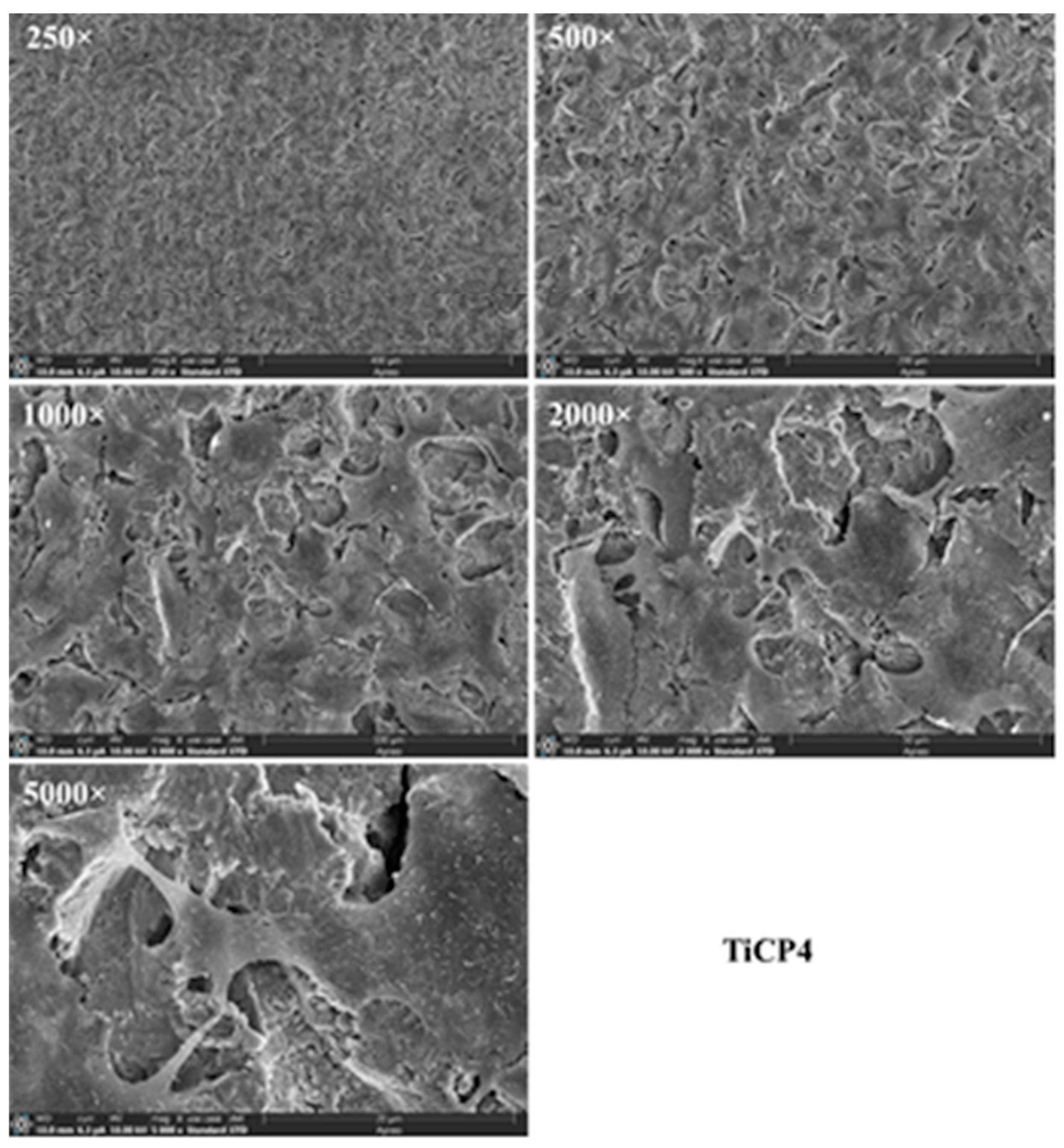
3.3. Cell Adhesion
4. Discussion
5. Conclusions
Supplementary Materials
Author Contributions
Funding
Data Availability Statement
Acknowledgments
Conflicts of Interest
References
- Adali, U.; Sütel, M.; Yassine, J.; Mao, Z.; Müller, W.-D.; Schwitalla, A.D. Influence of sandblasting and bonding on the shear bond strength between differently pigmented polyetheretherketone [PEEK] and veneering composite after artificial aging. Dent. Mater. J. 2024, 40, 1123–1127. [Google Scholar] [CrossRef]
- Gomes, A.L.; Castillo-Oyagu, R.; Lynch, D.C.; Montero, J.; Albaladejo, A. Influence of sandblasting granulometry and resin cement composition on microtensile bond strength to zirconia ceramic for dental prosthetic frameworks. J. Dent. 2013, 41, 31–41. [Google Scholar] [CrossRef]
- Deng, Z.; Liang, J.; Fang, N.; Li, X. Integration of collagen fibers in connective tissue with dental implant in the transmucosal region. Int. J. Biol. Macromol. 2022, 208, 833–843. [Google Scholar] [CrossRef] [PubMed]
- Alao, A.R. Optimization of surface roughness, phase transformation and shear bond strength in sandblasting process of YTZP using statistical machine learning. J. Mech. Behav. Biomed. Mater. 2024, 150, 106245. [Google Scholar] [CrossRef]
- Corvino, E.; Pesce, P.; Mura, R.; Marcano, E.; Canullo, L. Influence of modified titanium abutment surface on peri-implant soft tissue behavior: A systematic review of in vitro studies. Int. J. Oral Maxillofac. Implants 2020, 5, 503–519. [Google Scholar] [CrossRef]
- Supriadi, S.; Whulanza, Y.; Mahendra, T.A.; Dewi, R.S.; Kusdhany, S.L.; Matharand, P.R.; Umas, R.A. The Preliminary Development of a Friction-Based Lateral Screw-Retained Dental Crown—A Comparison between the Prototype Surface Treatment and the Retention Strength. Appl. Sci. 2024, 14, 660. [Google Scholar] [CrossRef]
- Monsalve-Guil, L.; Velasco-Ortega, E.; Moreno-Muñoz, J.; Núñez-Márquez, E.; Rondón-Romero, J.L.; Ortiz-García, I.; Nicolás-Silvente, A.; López-López, J.; Salgado-Peralvo, A.O.; Jiménez-Guerra, A. Clinical study with sandblasted dental implants: A 17-year retrospective follow up. Brit. J. Oral Max. Surg. 2024, 62, 191–196. [Google Scholar] [CrossRef]
- Behr, M.; Schneider-Feyrer, S.; Huber, C.; Krifka, S.; Rosentritt, M. The effect of sterilization and ultrasonic cleaning on resin cement interface of customized dental implant abutments. Brit. J. Oral Max. Surg. 2020, 104, 103660. [Google Scholar] [CrossRef]
- Talarico, M.; Fiorellini, J.; Nakajima, Y.; Omori, Y.; Takahisa, I.; Canullo, L. Mechanical outcomes, microleakage, and marginal accuracy at the implant-abutment interface of original versus nonoriginal implant abutments: A systematic review of in vitro studies. Biomed. Res. Int. 2018, 2018, 2958982. [Google Scholar] [CrossRef]
- Akula, S.K.J.; Ramakrishnan, H.; Sivaprakasam, A.N. Comparative evaluation of the microbial leakage at two different implant-abutment interfaces using a new sealant. J. Dent. Implant. Res. 2021, 40, 35–47. [Google Scholar] [CrossRef]
- Freifrau von Maltzahn, N.; Altmayer, N.; Kommerein, N.; Stiesch, M.; Kohorst, P. The influence of connection on the microleakage development of implant-supported fixed bridges. Eur. J. Prosthodont. Restor. Dent. 2021, 29, 112–118. [Google Scholar] [CrossRef]
- Smojver, I.; Bjelica, R.; Ćatić, A.; Budimir, A.; Vuletić, M.; Gabrić, D. Sealing efficacy of the original and third-party custom-made abutments—Microbiological in vitro pilot study. Materials 2022, 15, 1597. [Google Scholar] [CrossRef]
- Piattelli, A.; Vrespa, G.; Petrone, G.; Iezzi, G.; Annibali, S.; Scarano, A. Role of the Microgap Between Implant and Abutment: A Retrospective Histologic Evaluation in Monkeys. J. Periodontol. 2003, 74, 346–352. [Google Scholar] [CrossRef]
- Kim, S.; Lee, J.W.; Kim, J.-H.; Truong, V.M.; Park, Y.-S. The impact of Morse taper implant design on microleakage at implant-healing abutment interface. Dent. Mater J. 2022, 41, 767–773. [Google Scholar] [CrossRef]
- Balza, J.C.; Zujur, D.; Gil, L.; Subero, R.; Dominguez, E.; Delvasto, P.; Alvarez, J. Sandblasting as a surface modification technique on titanium aloys for biomedical applications: Abrasive particle behavior, IOP Conf. Series: Mater. Sci. Eng. 2013, 45, 012004. [Google Scholar] [CrossRef]
- Okada, M.; Hara, E.S.; Yabe, A.; Okada, K.; Shibata, Y.; Torii, Y.; Nakano, T.; Matsumoto, T. Titanium as an instant adhesive for biological soft tissue. Adv. Mater. Interfaces 2020, 7, 1902089. [Google Scholar] [CrossRef]
- Wang, Y.; Okada, M.; Xie, S.C.; Jiao, Y.Y.; Hara, E.S.; Yanagimoto, H.; Fukumoto, T.; Matsumoto, T. Immediate soft-tissue adhesion and mechanical properties of Ti6Al4V aloy after long-term acid treatment. J. Mater. Chem. B 2021, 9, 8348–8354. [Google Scholar] [CrossRef]
- Yabe, A.; Okada, M.; Hara, E.S.; Torii, Y.; Matsumoto, T. Self-adhering implantable device of titanium: Enhanced soft-tissue adhesion by sandblast pretreatment. Colloids Surf. B Biointerfaces 2022, 211, 112283. [Google Scholar] [CrossRef]
- Larjava, H.; Koivisto, L.; Hakkinen, L.; Heino, J. Epithelial integrins with special reference to oral epithelia. J. Dent. Res. 2011, 90, 1367–1376. [Google Scholar] [CrossRef]
- Kohal, R.J.; Weng, D.; Bachle, M.; Strub, J.R. Loaded custom-made zirconia and titanium implants show similar osseointegration: An animal experiment. J. Periodontol. 2004, 75, 1262–1268. [Google Scholar] [CrossRef]
- Vigolo, P.; Giovani, A.; Majzoub, Z.; Cordili, G. A 4-year prospective study to assess peri-implant hard and soft tissues adjacent to titanium versus gold-alloy abutments in cemented single implant crowns. J. Prosthodont. 2006, 15, 250–256. [Google Scholar] [CrossRef] [PubMed]
- Donley, T.G.; Gillette, W.B. Titanium endosseous implant-soft tissue interface: A literature review. J. Periodontol. 1991, 62, 153–160. [Google Scholar] [CrossRef] [PubMed]
- Andrukhov, O.; Behm, C.; Blufstein, A.; Wehner, C.; Gahn, J.; Pippenger, B.; Wagner, R.; Rausch-Fan, H. Effect of implant surface material and roughness to the susceptibility of primary gingival fibroblasts to inflammatory stimuli. Dent. Mater. 2020, 36, e194–e205. [Google Scholar]


| Property | Ti | Ti6Al4V |
|---|---|---|
| Density, g/cm3 | 4.51 | 4.43 |
| Melting point, °C | 1660 | 1660 |
| Tensile strength, MPa | 680 | 950 |
| Yield strength, MPa | 560 | 850 |
| Poisson’s ratio | 0.34–0.40 | 0.34–0.38 |
| Elastic modulus, GPa | 105–120 | 110–114 |
| Elongation at break, % | 23 | 14 |
| Hardness (Vickers) | 250 | 349 |
| Blasting Material | Size Range, [mm] | Working Pressure, [Bar] |
|---|---|---|
| 1. White electrocorundum F90, mixed with sintered hydroxyapatite with a particle size ≤ 63 µm, in a ratio of 3:1 | 0.15–0.20 | 6 |
| 2. White electrocorundum F90, mixed with sintered hydroxyapatite with a particle size ≤ 63 µm, in a ratio of 3:1 | 0.15–0.20 | 3 |
| 3. Fine white electrocorundum mixed with sintered hydroxyapatite with a particle size ≤ 63 µm, in a ratio of 3:1 | 0.10–0.15 | 6 |
| 4. Fine white electrocorundum mixed with sintered hydroxyapatite with a particle size ≤ 63 µm, in a ratio of 3:1 | 0.10–0.15 | 3 |
| 5. White electrocorundum F90 | 0.15–0.20 | 6 |
| 6. White electrocorundum F90 | 0.15–0.20 | 3 |
| 7. Fine white electrocorundum | 0.10–0.15 | 6 |
| 8. Fine white electrocorundum | 0.10–0.15 | 3 |
| 9. Glass balls | 0.04–0.07 | 6 |
| 10. Glass balls | 0.04–0.07 | 3 |
| 11. Olivine | 0.1–0.5 | 6 |
| 12. Olivine | 0.1–0.5 | 3 |
| 13. Red garnet | 0.40–0.80 | 6 |
| 14. Red garnet | 0.40–0.80 | 3 |
| 15. Brown electrocorundum | 0.120–0.212 | 6 |
| 16. Brown electrocorundum | 0.120–0.212 | 3 |
| Blasting Material | Digital Micrographs, 4× |
|---|---|
| White electrocorundum F90 of particle size 0.15–0.20 mm mixed With sintered hydroxyapatite, 2× | 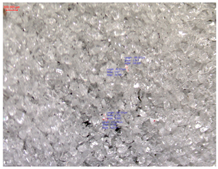 |
| White electrocorundum of particle size 0.10–0.15 mm mixed With sintered hydroxyapatite, 2× | 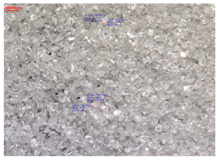 |
| White electrocorundum F90 particle size 0.15–0.20 mm, 2× | 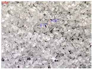 |
| White electrocorundum F90 particle size 0.15–0.20 mm, 2× | 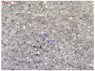 |
| Blasting Material | Digital Micrographs, 4× |
|---|---|
| Glass balls, 0.04–0.07 mm | 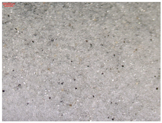 |
| Olivine, particle size 0–0.5 mm, 2× | 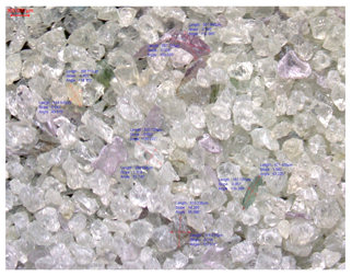 |
| Red garnet, particle size 0.40–0.80 mm, 2× | 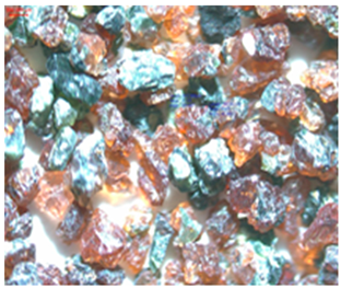 |
| Brown electrocorundum, particle size 0.120–0.212 mm, 2× | 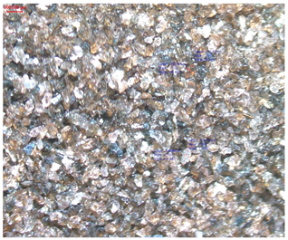 |
| Sample | Ra, Ti6Al4V, [µm] | Ra, Ti, [µm] |
|---|---|---|
| Blank, unblasted | 0.1354 | 0.2055 |
| 1-10 | 1.7703 | 1.0704 |
| 1-20 | 1.3463 | 1.4513 |
| 1-60 | 1.5043 | 1.4993 |
| 2-10 | 1.3472 | 1.1449 |
| 2-20 | 1.1422 | 1.1645 |
| 2-60 | 1.2295 | 1.1385 |
| 3-10 | 0.9809 | 1.0121 |
| 3-20 | 1.1930 | 1.0399 |
| 3-60 | 1.0652 | 1.0389 |
| 4-10 | 1.0480 | 1.1670 |
| 4-20 | 1.0733 | 1.8941 |
| 4-60 | 1.0252 | 0.9378 |
| 5-10 | 1.0746 | 1.0504 |
| 5-20 | 1.5539 | 1.1124 |
| 5-60 | 1.4036 | 1.3237 |
| 6-10 | 0.8885 | 1.8142 |
| 6-20 | 1.3938 | 0.9965 |
| 6-60 | 1.3708 | 1.4875 |
| 7-10 | 1.7690 | 0.9348 |
| 7-20 | 1.3630 | 0.9550 |
| 7-60 | 1.8821 | 0.9795 |
| 8-10 | 0.8411 | 0.8480 |
| 8-20 | 0.8610 | 0.8960 |
| 8-60 | 1.0868 | 1.3878 |
| Sample | Ra, Ti6Al4V, [µm] | Ra, Ti, [µm] |
|---|---|---|
| Blank, unblasted | 0.1354 | 0.2055 |
| 9-10 | 0.2623 | 0.2522 |
| 9-20 | 0.1886 | 0.2336 |
| 9-60 | 0.2613 | 0.2181 |
| 10-10 | 0.2526 | 0.2791 |
| 10-20 | 0.1833 | 0.2750 |
| 10-60 | 0.2588 | 0.2556 |
| 11-10 | 1.6319 | 1.3071 |
| 11-20 | 1.7691 | 1.4519 |
| 11-60 | 1.7595 | 1.5617 |
| 12-10 | 1.2783 | 1.2256 |
| 12-20 | 1.2737 | 1.0687 |
| 12-60 | 1.4867 | 1.5177 |
| 13-10 | 1.4561 | 2.8206 |
| 13-20 | 1.9282 | 2.5769 |
| 13-60 | 2.5735 | 2.4411 |
| 14-10 | 1.9579 | 2.1483 |
| 14-20 | 1.9228 | 2.1547 |
| 14-60 | 2.5234 | 2.5275 |
| 15-10 | 0.9990 | 0.9317 |
| 15-20 | 1.2356 | 1.1485 |
| 15-60 | 1.0039 | 1.0423 |
| 16-10 | 0.8467 | 1.0445 |
| 16-20 | 0.9462 | 0.9881 |
| 16-60 | 1.0707 | 1.0627 |
Disclaimer/Publisher’s Note: The statements, opinions and data contained in all publications are solely those of the individual author(s) and contributor(s) and not of MDPI and/or the editor(s). MDPI and/or the editor(s) disclaim responsibility for any injury to people or property resulting from any ideas, methods, instructions or products referred to in the content. |
© 2024 by the authors. Licensee MDPI, Basel, Switzerland. This article is an open access article distributed under the terms and conditions of the Creative Commons Attribution (CC BY) license (https://creativecommons.org/licenses/by/4.0/).
Share and Cite
Ciobotaru, I.-A.; Stoicanescu, M.; Budei, R.; Cojocaru, A.; Vaireanu, D.-I. Considerations Regarding Sandblasting of Ti and Ti6Al4V Used in Dental Implants and Abutments as a Preconditioning Stage for Restorative Dentistry Works. Appl. Sci. 2024, 14, 7365. https://doi.org/10.3390/app14167365
Ciobotaru I-A, Stoicanescu M, Budei R, Cojocaru A, Vaireanu D-I. Considerations Regarding Sandblasting of Ti and Ti6Al4V Used in Dental Implants and Abutments as a Preconditioning Stage for Restorative Dentistry Works. Applied Sciences. 2024; 14(16):7365. https://doi.org/10.3390/app14167365
Chicago/Turabian StyleCiobotaru, Ioana-Alina, Maria Stoicanescu, Roxana Budei, Anca Cojocaru, and Danut-Ionel Vaireanu. 2024. "Considerations Regarding Sandblasting of Ti and Ti6Al4V Used in Dental Implants and Abutments as a Preconditioning Stage for Restorative Dentistry Works" Applied Sciences 14, no. 16: 7365. https://doi.org/10.3390/app14167365
APA StyleCiobotaru, I.-A., Stoicanescu, M., Budei, R., Cojocaru, A., & Vaireanu, D.-I. (2024). Considerations Regarding Sandblasting of Ti and Ti6Al4V Used in Dental Implants and Abutments as a Preconditioning Stage for Restorative Dentistry Works. Applied Sciences, 14(16), 7365. https://doi.org/10.3390/app14167365