Article

Single EX-CCCII-Based First-Order Versatile Active Filter

1
Department of Telecommunications Engineering, School of Engineering, King Mongkut’s Institute of Technology Ladkrabang, Bangkok 10520, Thailand
2
Department of Microelectronics, Brno University of Technology, Technická 10, 601 90 Brno, Czech Republic
3
Department of Electrical Engineering, Brno University of Defence, Kounicova 65, 662 10 Brno, Czech Republic
4
Department of Electrical Engineering, Czestochowa University of Technology, 42-201 Czestochowa, Poland
*
Author to whom correspondence should be addressed.
Appl. Sci. 2024, 14(16), 7396; https://doi.org/10.3390/app14167396 (registering DOI)
Submission received: 22 July 2024 / Revised: 18 August 2024 / Accepted: 19 August 2024 / Published: 21 August 2024
(This article belongs to the Section Electrical, Electronics and Communications Engineering)

Abstract

:
This paper presents a new current-mode first-order versatile active filter employing one extra-x second-generation current controlled current conveyor (EX-CCCII) and one grounded capacitor. The proposed filter can realize first-order filtering functions of a low-pass filter (LPF), high-pass filter (HPF), and all-pass filter (APF) within the same topology with low-input and high-output impedances required for current-mode circuits. This multiple-output EX-CCCII-based filter can provide six transfer functions as both non-inverting and inverting filtering functions of the LPF, HPF, and APF are obtained. The filter also offers electronic control of the pole frequency of all filtering. The proposed current-mode filter can be applied to work as a mixed-mode active filter, namely in the transadmittance-mode (TAM), transimpedance-mode (TIM), and voltage-mode (VM). Each operation mode can provide six transfer functions. The proposed filter was simulated and designed using SPICE and 0.18 µm CMOS technology. Experimental results using the commercially available integrated circuit AD844 were used to confirm the functionality of the new circuits.

1. Introduction

Current-mode circuits are usually implemented using second-generation current conveyors (CCII) [1] as they offer a better dynamic range, bandwidth, and linearity compared to operational amplifiers (op-amp) [2,3]. The conventional CCII is a single-end active block, it has y-, x-, and z-terminals, and usually requires many passive components to realize applications. In order to overcome these limitations and extend the range of the CCII, other functional blocks have been proposed. Some examples are the differential difference current conveyor (DDCC) [4] or the fully differential second-generation current conveyor (FDCCII) [5], which enables arithmetic operations. Further examples include the dual-x second-generation current conveyor (DX-CCII) [6] and the extra-x second-generation current conveyor (EX-CCII) [7], which both provide multiple x- and z-terminals. The extra-x current controlled second-generation current conveyor (EX-CCCII) has also been proposed [8]. Compared to the EX-CCII, the EX-CCCII considers the intrinsic resistance at the x-terminal, which can be electronically controlled by a bias current. This is advantageous in applications because it can be used as a tuning parameter. Therefore, EX-CCCII-based circuits are able to be free of passive resistors while offering the possibility of electronic tuning.
First-order filters are fundamental circuits used to construct biquad-based odd high-order filters, multiphase sinusoidal oscillators, and quadrature oscillators [9,10,11]. The first-order filter is a single pole frequency filter; therefore, three first-order filters can be realized: the low-pass filter (LPF), high-pass filter (HPF), and all-pass filter (APF). Many first-order filters are available in the literature [12,13,14,15,16,17,18,19,20,21,22,23,24,25,26,27,28,29,30,31,32,33,34,35,36,37,38,39,40,41,42,43,44,45,46,47,48]. Depending on the input and output signals, these first-order filters can be categorized into three operation modes: voltage-mode (VM) [12,13,14,15,16,17,18,19,20,21,22], current-mode (CM) [23,24,25,26,27,28,29,30,31,32,33,34,35,36,37,38], and mixed-mode (MM) [39,40,41,42,43]. The filter structures in [12,13,14,15,16,17,18,19,20,21,22,23,24,25,26,27,28,29,30,31,32,33,34,35,36,37,38,39,40,41,42,43,44,45,46,47,48] can realize the LPF, HPF, and APF in the same topology.
This work focuses on a current-mode first-order filter that offers the LPF, HPF, and APF in a single topology. The CM first-order filters in [23,24,25,26,27,28,29,30,31,32,33,34,35,36,37,38] use various active elements, such as CFTAs (current follower transconductance amplifiers) [23], current amplifiers [24], current conveyors [25,26,27,28,29,32,34,38], CFOAs (current feedback operational amplifiers) [30], CBTAs (current backward transconductance amplifiers) [31], CCTAs (current conveyor transconductance amplifiers) [33,36], CDTAs (current differencing transconductance amplifiers) [35], and OTAs (operational transconductance amplifiers) [37]. The filter structures in [23,25,26,31,32,33,34,35,36] use only one active element, but these filters have some disadvantages: (i) they do not provide both non-inverting and inverting transfer functions of the LPF, HPF, and APF [25,26,31,32,33,34,35,36], which may lead to a need for additional non-inverting/inverting amplifiers for applications; (ii) they do not enable electronic tuning capabilities [26], making it difficult to compensate for the filter cut-off frequency when circuit parameters deviate due to temperature changes; and (iii) they use a floating capacitor [32], which is not ideal for integrated circuits because it is not easy to compensate for the stray capacitance.
Filters that can implement the VM, CM, transimpedance-mode (TIM), and transadmittance-mode (TAM) from the same configuration are usually classified as universal mixed-mode filters. For first-order universal filters, three filtering functions can be obtained, i.e., the LPF, HPF, and APF. The voltage input, current output of the TAM and current input, and voltage output of the TIM can be used to interconvert between voltage and current modes, which is an advantage of mixed-mode filters [49]. Therefore, various configurations of mixed-mode first-order universal filters have been investigated [39,40,41,42,43]. The circuit in [39] uses two OTAs, seven MOS transistors, and one capacitor; the circuit in [40] uses two OTAs and one capacitor; the circuit in [41] uses one CFOA, three resistors, and one capacitor; the circuit in [42] uses one VDGA and one resistor; and the circuit in [43] uses one EXCCTA, one resistor, and one capacitor. However, these mixed-mode filters cannot realize both non-inverting and inverting transfer functions of the LPF, HPF, and APF of the CM, VM, TIM, and TAM within the same topology—in other words, they are incapable of providing a total of 24 transfer functions.
EX-CCIIs and EX-CCCIIs were used to realize the first-order universal filters in [44,45,46,47,48]. The filter in [44] provides a voltage-mode APF; the filter in [45] provides a current-mode LPF, six APF transfer functions (both non-inverting and inverting) of the current-mode LPF, HPF, and APF, and three transfer functions (LPF, HPF, and APF) of the TAM; the filter in [46] provides three transfer functions of the current-mode LPF, HPF, and APF; the filter in [47] provides three transfer functions of the voltage-mode LPF, HPF, and APF by appropriately programming the current gain of the EX-CCCII; and the filter in [48] provides three transfer functions of the LPF, HPF, and APF.
In this paper, we propose a current-mode first-order versatile active filter with a single EX-CCCII and a grounded capacitor. The proposed first-order filter can realize non-inverting and inverting current transfer functions of the LPF, HPF, and APF (six filter responses) and offers the possibility of electronic tuning of the pole frequency of all filter responses. Favorable current-mode circuits and low-input and high-output impedances are available. Due to the low-input and high-output impedances of the proposed filter, it can be used for TAM, TIM, and VM (universal mixed-mode filter) operation. In the case of the TAM, a resistor is used to convert the input voltage to output current; in the case of the TIM, grounded resistors are used to convert the output currents to output voltages; and in the case of the VM, a resistor is used to convert the input voltage of the VM to the input current of the CM, and the output currents of the CM are converted to output voltages of the VM by grounded resistors. Thus, the filter offers 24 transfer functions of the LPF, HPF, and APF of the CM, TIM, TAM, and VM. The proposed active filters are simulated and designed using SPICE with 0.18 µm CMOS technology. Experimental results using a commercially available AD844 IC are used to confirm the functionality of the new configurations.

2. Circuit Description

2.1. EX-CCCII

Figure 1a shows the symbolic representation of the EX-CCCII, and Figure 1b shows the equivalent circuit. From Figure 1b, it can be seen that this EX-CCCII has two intrinsic resistances, R x 1 and R x 2 , on terminals x1 and x2, respectively. The characteristics of the EX-CCCII ports in Figure 1 are given by
I y V x 1 V x 2 I z 1 I z 2 = 0 0 0 0 0 1 R x 1 0 0 0 1 0 R x 2 0 0 0 ± 1 0 0 0 0 0 ± 1 0 0 V y I x 1 I x 2 V z 1 V z 2
The plus (+) and minus (−) signs here mean that the EX-CCCII can provide plus and minus z-terminals in a single device.
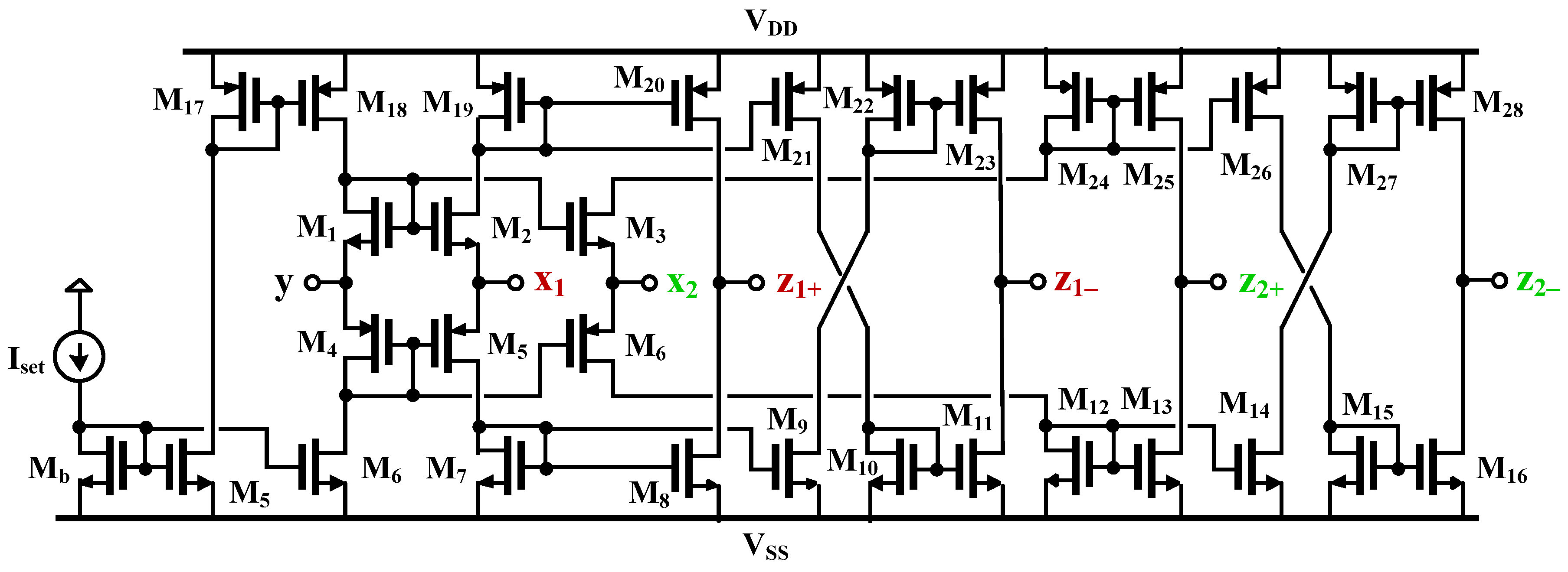
Figure 2 shows the structure of the CMOS EX-CCCII [50]. The transistors M1–M6 are connected in the so-called translinear loop configuration [51], while transistors Mb, M7, M8, M19, M20, and the biasing current Iset provide the bias current required for the circuit. Assuming that the NMOS (M1–M3) and PMOS (M4–M6) transistors are matched (i.e., V G S 1 = V G S 2 = V G S 3 and V G S 4 = V G S 5 = V G S 6 ), and the transistors Mb, M5, M6, M17, and M18 are identical, the relationship V y = V x 1 = V x 2 can be obtained and the intrinsic resistances at the x1- and x2-terminals ( R x 1 and R x 2 ), assuming operation in strong inversion, can be determined by [50]
R x 1 = R x 2 = 1 2 I s e t C o x μ p W L p + μ n W L n
where I s e t is the biasing current, C o x is the oxide capacitance per unit area, μ n and μ p are the mobilities of the electrons and holes, respectively, and (W/L)n and (W/L)p are the channel width and length ratios of the NMOS and PMOS transistors, respectively. R x 1 and R x 2 can be controlled by the setting current I s e t .
At the output, the circuit consists of current mirrors. Transistors M7, M8, M19, and M20 are used to mirror the current from the x1- to z1+-terminals, and transistors M7, M9–M11, M19, and M21–M23 are used to mirror the current from the x1- to z1−-terminals. The multiple z1+- and z1−-terminals can be obtained using complementary current mirrors. Here, transistors M12, M13, M24, and M25 are used to mirror the current from the x2- to z2+-terminals, and transistors M12, M14–M16, M24, and M26–M28 are used to mirror the current from the x2- to z2−-terminals. Similarly, complementary current mirrors can be used to obtain multiple z2+- and z2−-terminals. Thus, the relations of I x 1 = I z 1 + = I z 1 and I x 2 = I z 2 + = I z 2 of the EX-CCCII can be obtained.

2.2. Current-Mode First-Order Versatile Active Filter

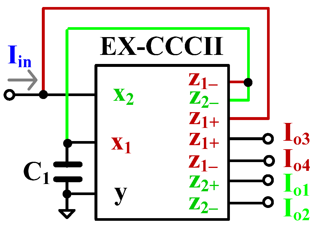
Figure 3 presents the proposed first-order universal filter with the current mode. The filter uses only one active EX-CCCII block and one grounded capacitor, thus achieving a minimum number of active and passive elements. The input current signal of the current filter is fed to the low-impedance terminal x of the EX-CCCII and the output currents are obtained from the high-impedance terminals of the EX-CCCII. Thus, the proposed filter has low-input and high-output impedances, which is desirable for current-mode circuits. The circuit uses a grounded capacitor, which is ideal for integrated circuits and easily compensates for the stray capacitance. Using (1) and nodal analysis, the output currents I o 1 , I o 2 , I o 3 , and I o 4 can be expressed as
HPF I o 1 = I o 2 = s C 1 R x 1 s C 1 R x 1 + 1 I i n
LPF I o 3 = I o 4 = 1 s C 1 R x 1 + 1 I i n
APF + I A P + = I o 2 + I o 3 = 1 s C 1 R x 1 1 + s C 1 R x 1 I i n = s C 1 R x 1 1 s C 1 R x 1 + 1 I i n
APF I A P = I o 1 + I o 4 = s C 1 R x 1 1 s C 1 R x 1 + 1 I i n
The circuit offers first-order non-inverting and inverting transfer functions of the HPF, LPF, APF; thus, six transfer functions can be obtained in one circuit, where APF+ is the phase lag APF (non-inverting APF), and APF− is the phase lead APF (inverting APF).
The pole frequency of the filters can be given by
ω o = 1 C 1 R x 1
The pole frequency of all filtering functions can be electronically controlled by R x 1 via the bias current I s e t .

2.3. Applications to a Mixed-Mode First-Order Active Filter

Thanks to its low-input and high-output current-mode, the proposed current-mode active filter in Figure 3 can be applied to work as a TIM, TAM, and VM filter. Figure 4a shows the proposed TIM filter. From the transfer functions (3)–(6) of the current-mode filter, and using resistors R o u t to convert the current outputs I o 1 , I o 2 , I o 3 , and I o 4 to the voltage outputs V o 1 , V o 2 , V o 3 , V o 4 , V A P + , and V A P , the output voltages of the TIM filter can be expressed by
HPF V o 1 = V o 2 = R o u t s C 1 R x 1 s C 1 R x 1 + 1 I i n
LPF V o 3 = V o 4 = R o u t 1 s C 1 R x 1 + 1 I i n
APF + V A P + = R o u t I o 2 + I o 3 = R o u t 1 s C 1 R x 1 1 + s C 1 R x 1 I i n                                                                                 = R o u t s C 1 R x 1 1 s C 1 R x 1 + 1 I i n
APF V A P = R o u t I o 1 + I o 4 = R o u t s C 1 R x 1 1 s C 1 R x 1 + 1 I i n
Figure 4b shows the proposed TAM filter. In this case, the resistor R i n is used to convert the voltage input V i n to the current input I i n . From the transfer functions (3)–(6) of the current-mode filter, the output currents of the TAM filter can be expressed by
HPF I o 2 = I o 1 = 1 R i n s C 1 R x 1 s C 1 R x 1 + 1 V i n
LPF I o 4 = I o 3 = 1 R i n 1 s C 1 R x 1 + 1 V i n
APF + I A P + = 1 R i n I o 4 + I o 1 = 1 R i n 1 s C 1 R x 1 1 + s C 1 R x 1 V i n                                                                                         = 1 R i n s C 1 R x 1 1 s C 1 R x 1 + 1 V i n
APF I A P = 1 R i n I o 2 + I o 3 = 1 R i n s C 1 R x 1 1 s C 1 R x 1 + 1 V i n
Figure 4c shows the proposed VM filter. In this case, the resistor R i n is used to convert the voltage input V i n to the current input I i n and the resistors R o u t are used to convert the current outputs I o 1 , I o 2 , I o 3 , and I o 4 to the voltage outputs V o 1 , V o 2 , V o 3 , V o 4 , V A P + , and V A P . Using the transfer functions (3)–(6) of the current-mode filter, the output voltages of the VM filter can be expressed by
HPF V o 2 = V o 1 = R o u t R i n s C 1 R x 1 s C 1 R x 1 + 1 V i n
LPF V o 4 = V o 3 = R o u t R i n 1 s C 1 R x 1 + 1 V i n
APF + V A P + = R o u t R i n I o 1 + I o 4 = R o u t R i n 1 s C 1 R x 1 1 + s C 1 R x 1 V i n                                                                                               = R o u t R i n s C 1 R x 1 1 s C 1 R x 1 + 1 V i n
APF V A P = R o u t R i n I o 2 + I o 3 = R o u t R i n s C 1 R x 1 1 s C 1 R x 1 + 1 V i n
For the VM filter, the voltage gain of the transfer functions can be given by R o u t / R i n .
It is evident that the proposed current-mode filter in Figure 3 can be used to realize TIM, TAM, and VM filters, and each operation mode can provide both non-inverting and inverting transfer functions of the LPF, HPF, and APF (six transfer functions). Thus, 18 transfer functions are provided. For the TIM, TAM, and VM filters, the circuit in Figure 3 needs additional external resistors; however, this can be obtained without changing the original topology. Thus, the proposed current-mode versatile active filter in Figure 4 can provide 24 transfer functions of the LPF, HPF, and APF of the CM, TAM, TIM, and VM.

2.4. Non-Idealities Analysis

Considering the EX-CCCII gain errors, the relationships of voltages and current terminals can be expressed as follows
    V x j = α j V y I z j = β j ± I x j
where α j is the voltage gain from the y-terminal to the xi-terminal, and β j ± is the current gain from the x j ± -terminals to the z j ± -terminals ( j = 1, 2). Ideally, α j and β j ± would be equal to 1. However, due to the EX-CCCII nonidealities, these unity gains will decrease by the voltage and current tracking errors. These can be expressed by β j ± = 1 ε j v ± and α j ± = 1 ε j i ± , where ε j v ± is the voltage tracking error and ε j i ± is the current tracking error.
Considering the nonidealities of the EX-CCCII, the output currents I o 1 , I o 2 , I o 3 , and I o 4 can be rewritten as
I o 1 = I o 2 = s C 1 R x 1 β 2 + 1 β 1 β 2 s C 1 R x 1 + 1 β 1 + β 1 + β 2 I i n
I o 3 = I o 4 = β 1 + β 2 s C 1 R x 1 + 1 β 1 + β 1 + β 2 I i n
From (21) and (22), the current tracking error (i.e., β 1 ) will cause a slight deviation from ideal characteristics in the HPF and LPF transfer functions.
Letting β 1   = 1, (21) and (22) can be rewritten as
I o 1 = I o 2 = s C 1 R x 1 β 2 s C 1 R x 1 + β 1 + β 2 I i n
I o 3 = I o 4 = β 1 + β 2 s C 1 R x 1 + β 1 + β 2 I i n
The output currents of the APF become
I A P + = I o 2 + I o 3 = β 1 + β 2 s C 1 R x 1 β 2 s C 1 R x 1 + β 1 + β 2 I i n = β 1 + β 2 s C 1 R x 1 β 2 s C 1 R x 1 + β 1 + β 2 I i n
I A P = I o 1 + I o 4 = s C 1 R x 1 β 2 β 1 + β 2 s s C 1 R x 1 + β 1 + β 2 I i n
The pole frequency of all filters can be rewritten as
ω o = β 1 + β 2 C 1 R x 1
Using the results for the EX-CCCII that include parasitic impedances in [50], the capacitance C 1 can be selected as C 1 > ( C z 1 + C z 2 ) to avoid parasitic capacitance effects to the pole frequency, where C z 1 and C z 2 are the parasitic capacitances at the z1−- and z2−-terminals, respectively. To avoid the parasitic impedance effects on the pole frequency, R x 1 can be selected as R x 1 < R z 1 R z 2 .

3. Simulation Results

To validate the proposed universal active filter, the EX-CCCII was designed in SPICE using standard n-well CMOS 0.18 μm technology. The supply voltage was set to ±0.9 V. The width and length of the MOS transistors for the EX-CCCII are listed in Table 1 [50]. Simulated performances of the EX-CCCII are summarized in Table 2.
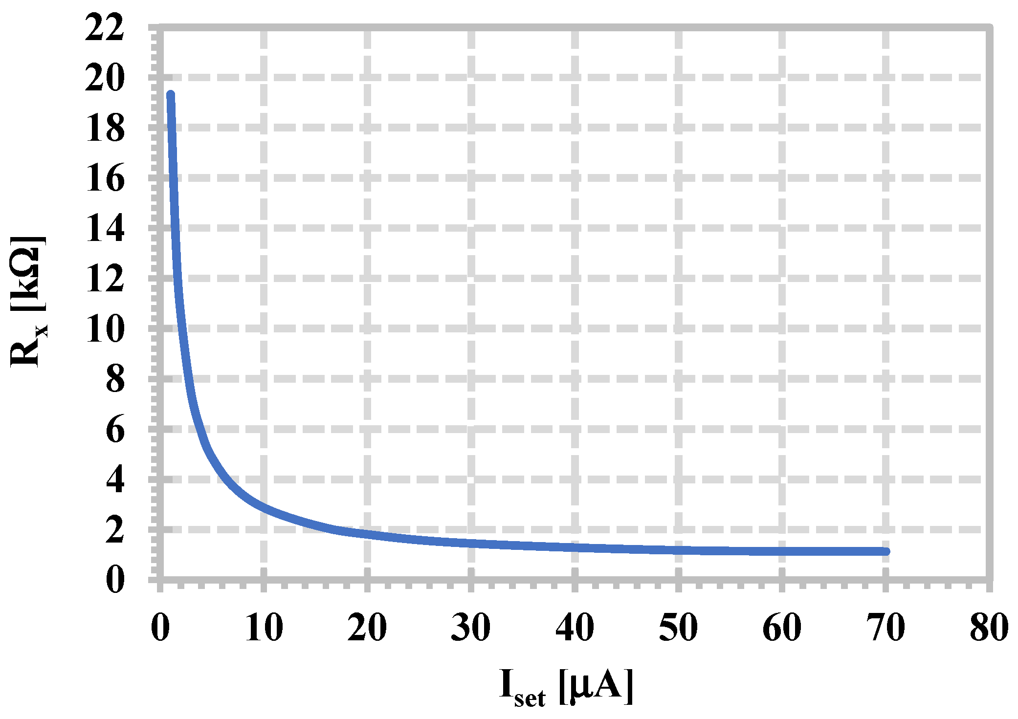
The simulated intrinsic resistances R x ( R x = R x 2 = R x 2 ) against the setting current I s e t are shown in Figure 5. The intrinsic resistances R x varied in square-root form from 13.49 kΩ to 1.13 kΩ while the setting current I s e t was increased from 1.5 μA to 70 μA.
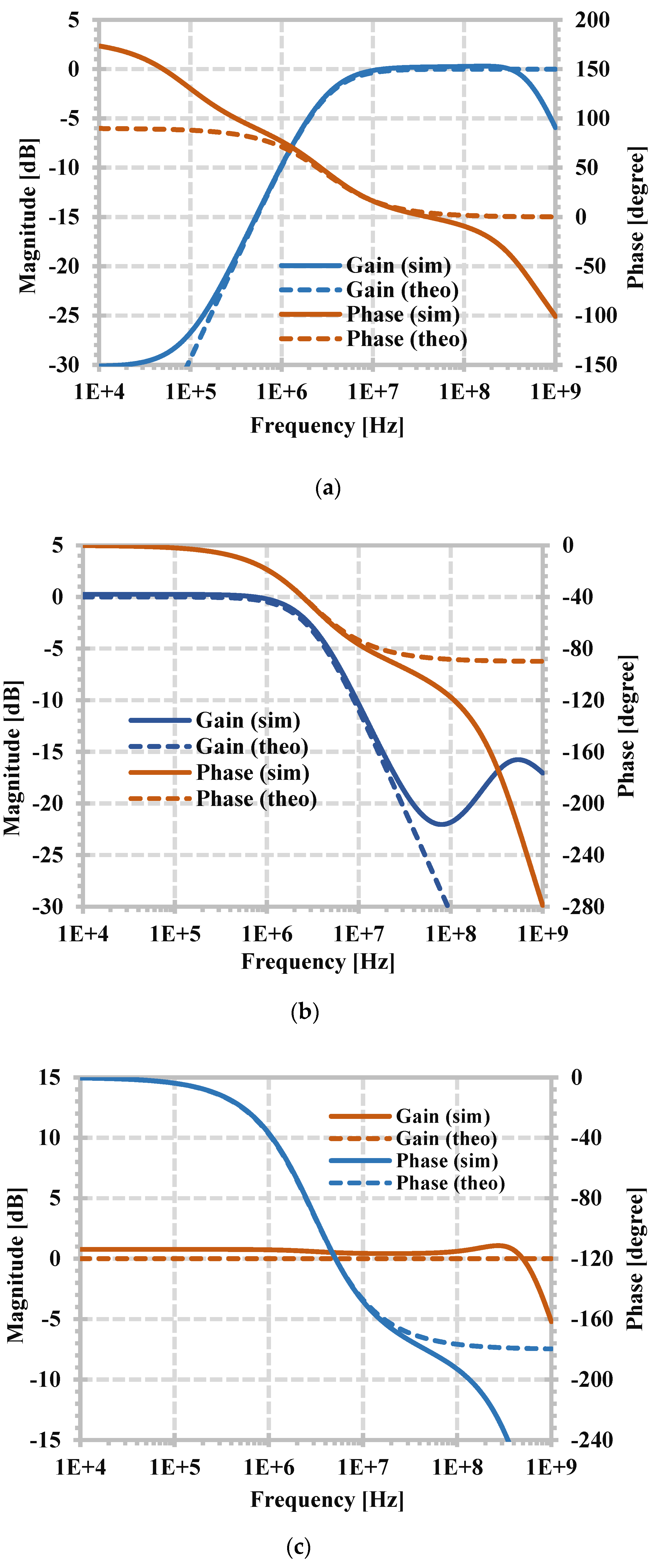
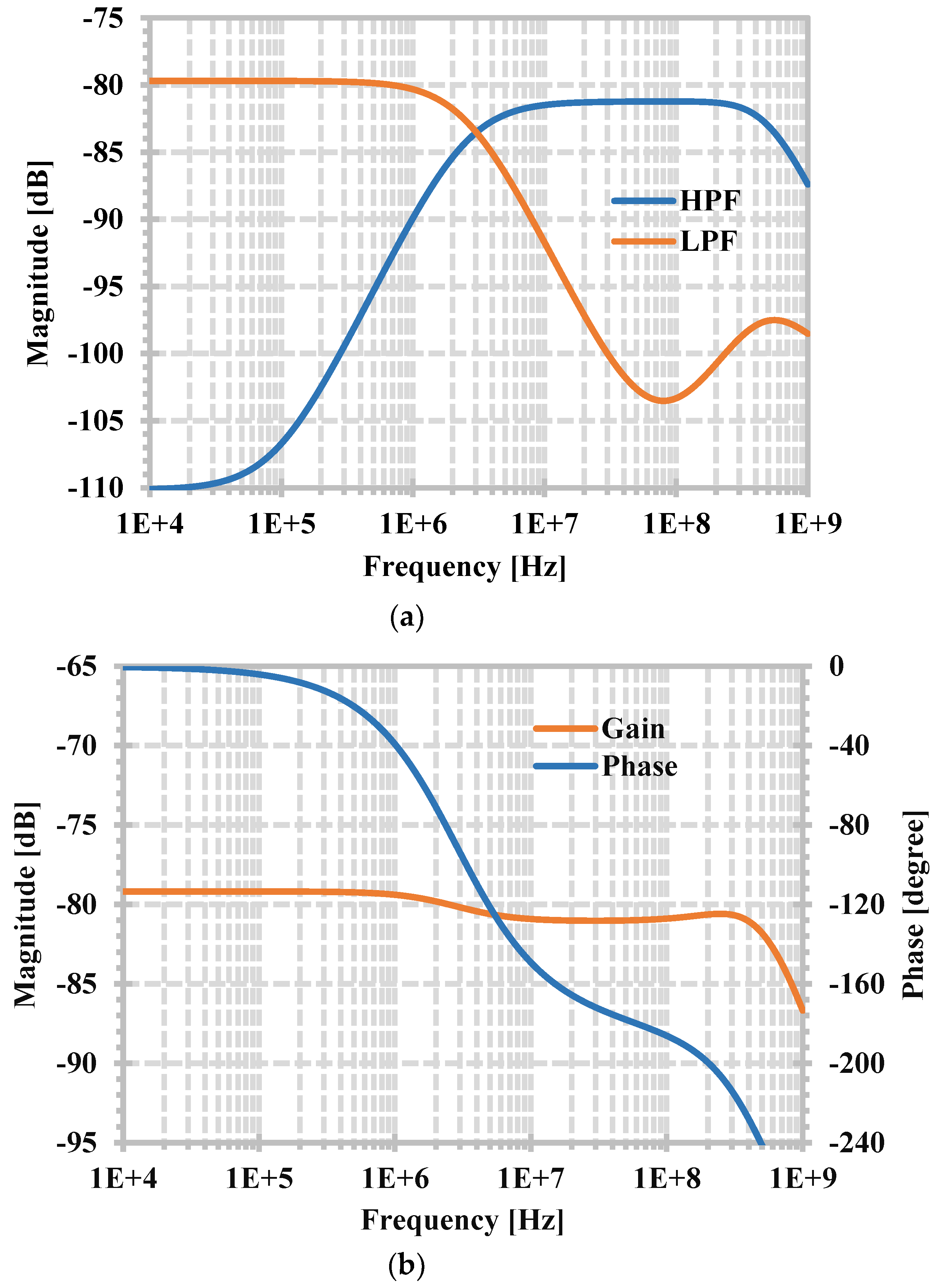
Figure 6 shows the simulated magnitude frequency responses of the HPF and LPF and the magnitude and phase frequency responses of the APF when the circuit was designed as C 1 = 30 pF and I s e t = 20 μA ( R x = 1.81 kΩ). The simulated pole frequency was 2.91 MHz, whereas the designed pole frequency was 2.93 MHz. The circuit consumed 0.558 mW of power, and the −3 dB bandwidth of the filter was 600 MHz. The theoretical value was used to confirm the simulation results, showing that the simulation results agree with the theory.
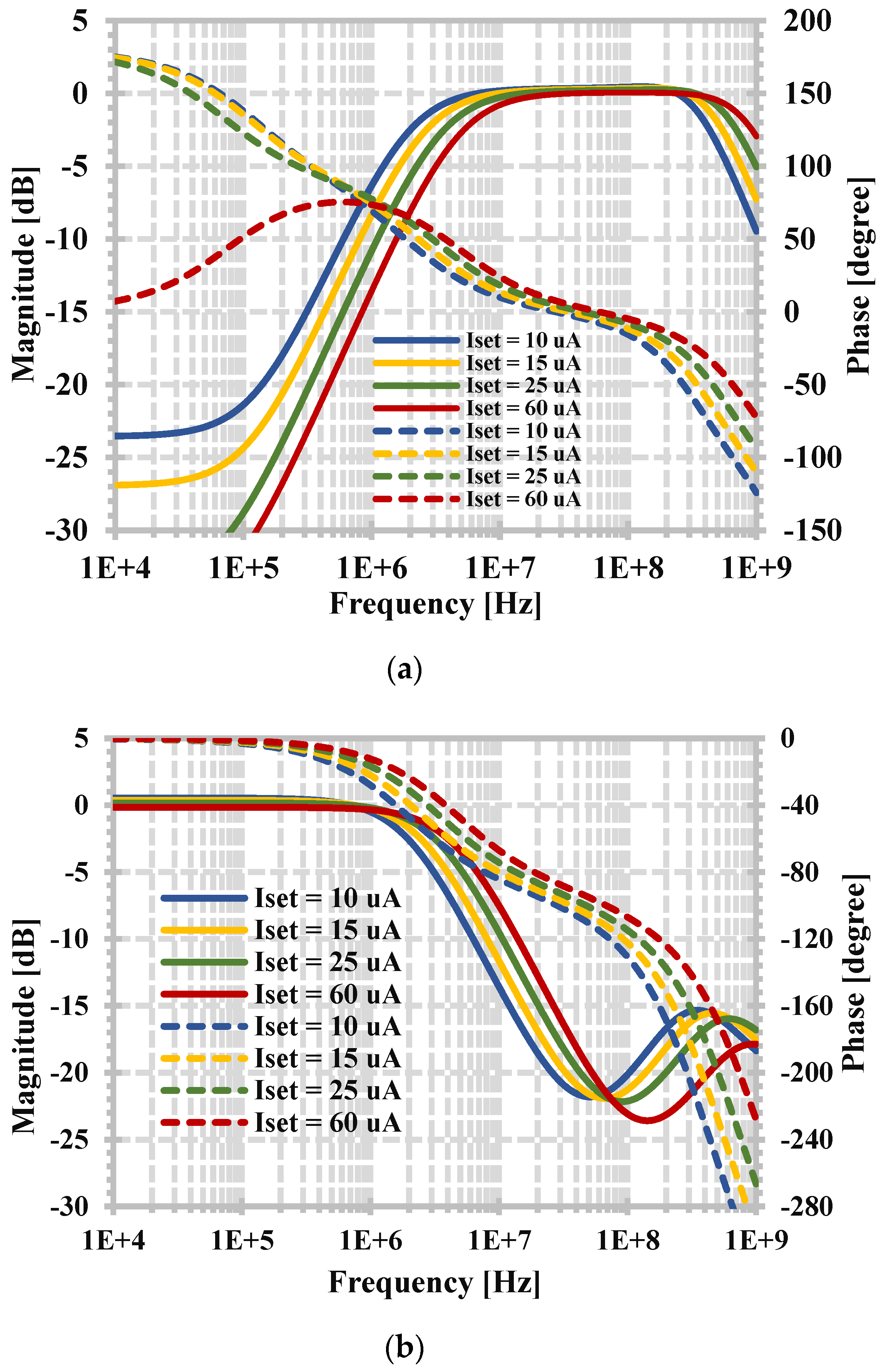
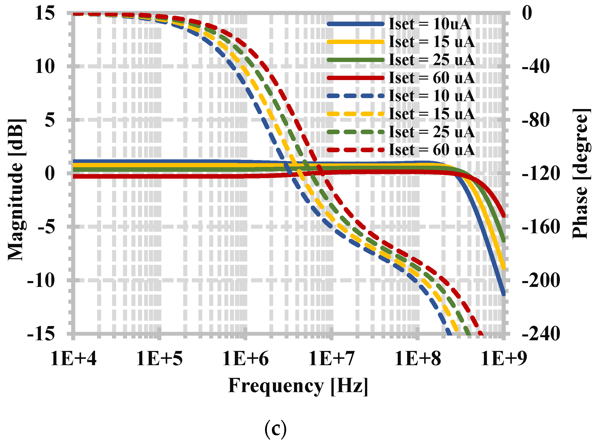
Figure 7 shows the simulated magnitude frequency responses of the HPF and LPF and the magnitude and phase frequency of the APF when the setting current I s e t (i.e., 10, 15, 25, or 60 μA) was used to vary the pole frequency. This result is confirmed by (7).
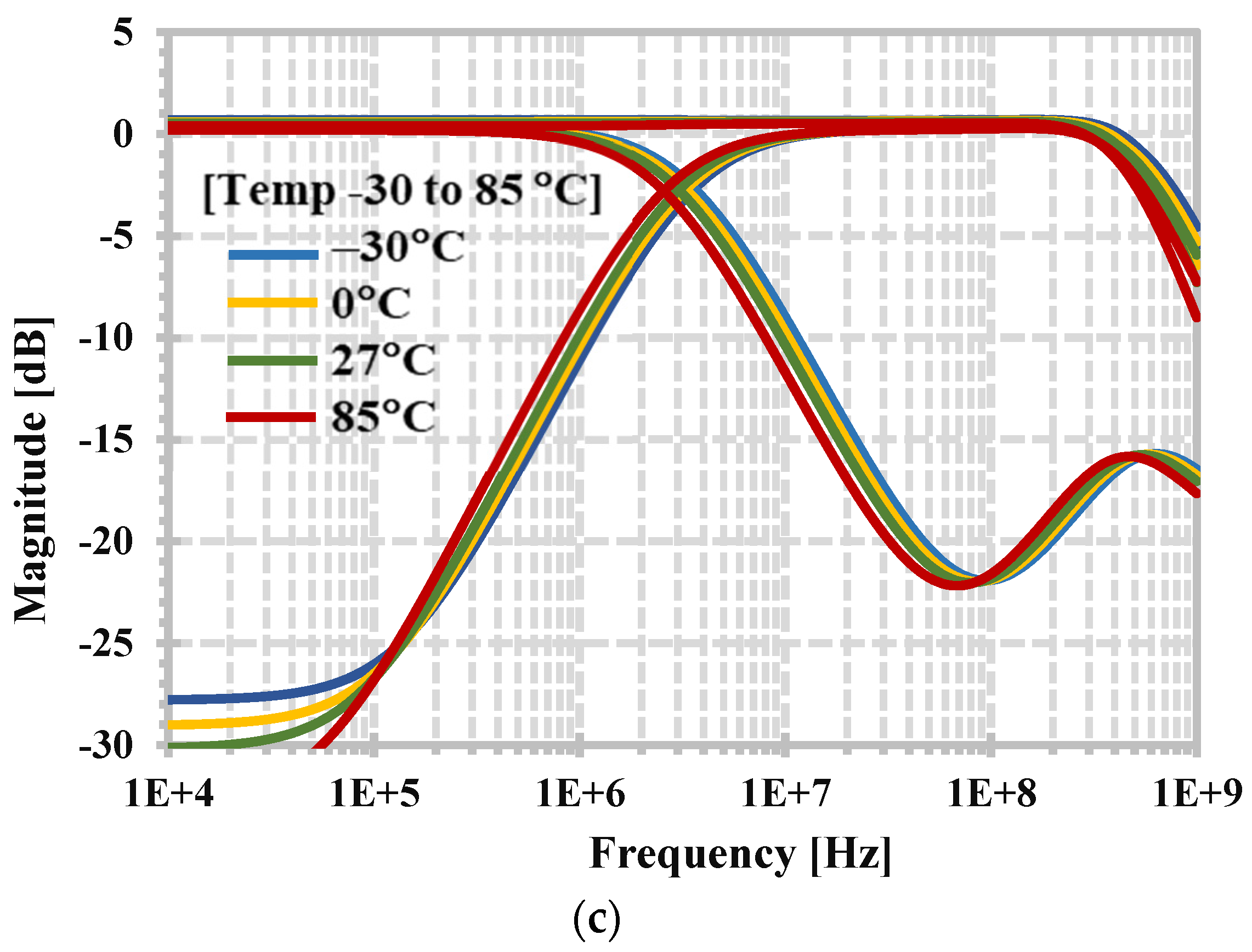
Figure 8 shows the simulated magnitude frequency responses of the HPF, LPF, and APF when several parameters were varied. Figure 8a shows the magnitude frequency responses when the threshold voltage in the CMOS process was varied by 10% (LOT tolerance); the curves are overlapped here. A Monte Carlo analysis with 200 runs was used for simulation and some simulated magnitude frequency responses were selected to be shown. This is used to represent a process variation. Figure 8b shows the magnitude frequency responses when the supply voltage was varied by ±10%, and Figure 8c shows the magnitude frequency responses when the temperature was set to −30, 0, 27, and 85 °C. Thus, the process–voltage–temperature (PVT) of the proposed filter can be confirmed by Figure 8.
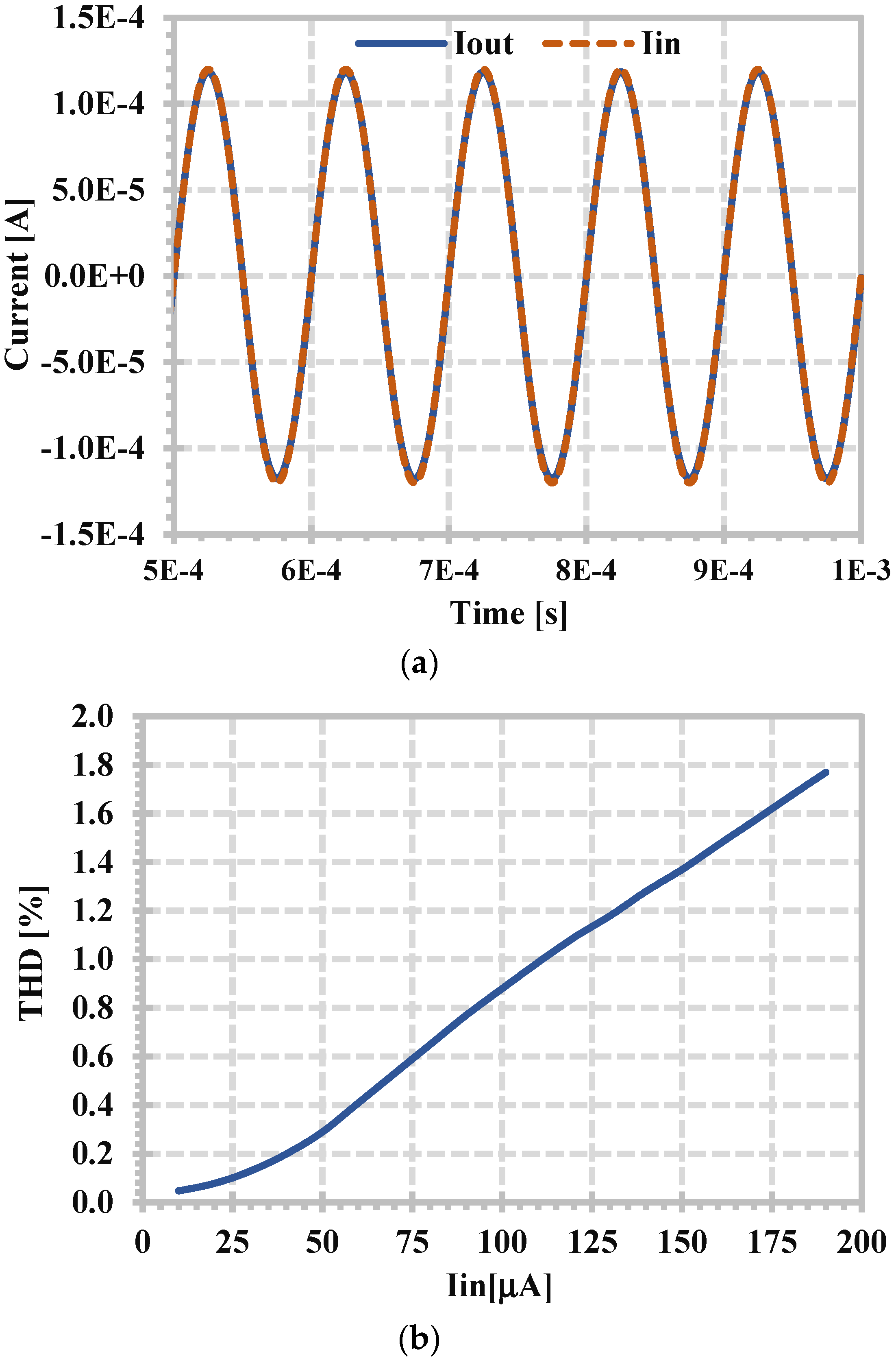
The linearity of the proposed filter was investigated. The LPF with the 2.85 MHz cut-off frequency was selected, and the in-band input frequency of 10 kHz was applied. Figure 9a shows the input and output waveforms of 120 µA for 1.09% of total harmonic distortion (THD). Figure 9b shows the overall THD against the amplitude of the input signal. Figure 10 shows the equivalent output current noise of the LPF. The integrated output noise in the 2.85 MHz bandwidth was calculated to be 13.45 nA, giving a dynamic range (DR) of 75.99 dB.
The properties comparison of the proposed first-order versatile filter with those of some first-order universal filters is shown in Table 3. The first-order universal filters in [32,33,42,43,47] were selected for comparison. The circuit in [32] was selected because it can offer six filtering responses within the same topology, and the circuits in [33,42,43,47] were selected because they use only a single active element. Compared with [32], the proposed circuit uses one active element, one grounded capacitor, and offers low-input and high-output impedance, which simplifies its application in a mixed-mode filter. Compared with the CM filter [33] and the VM filter [47], the proposed circuit offers six transfer functions of both non-inverting and inverting filtering functions of the LPF, HPF, and APF. The proposed filter offers larger current-mode functions and does not require passive/active resistors, as compared to the MM filters in [42,43]. If the proposed filter is applied to work as an MM filter that uses passive resistors similar to [42,43], it can provide 24 transfer functions.
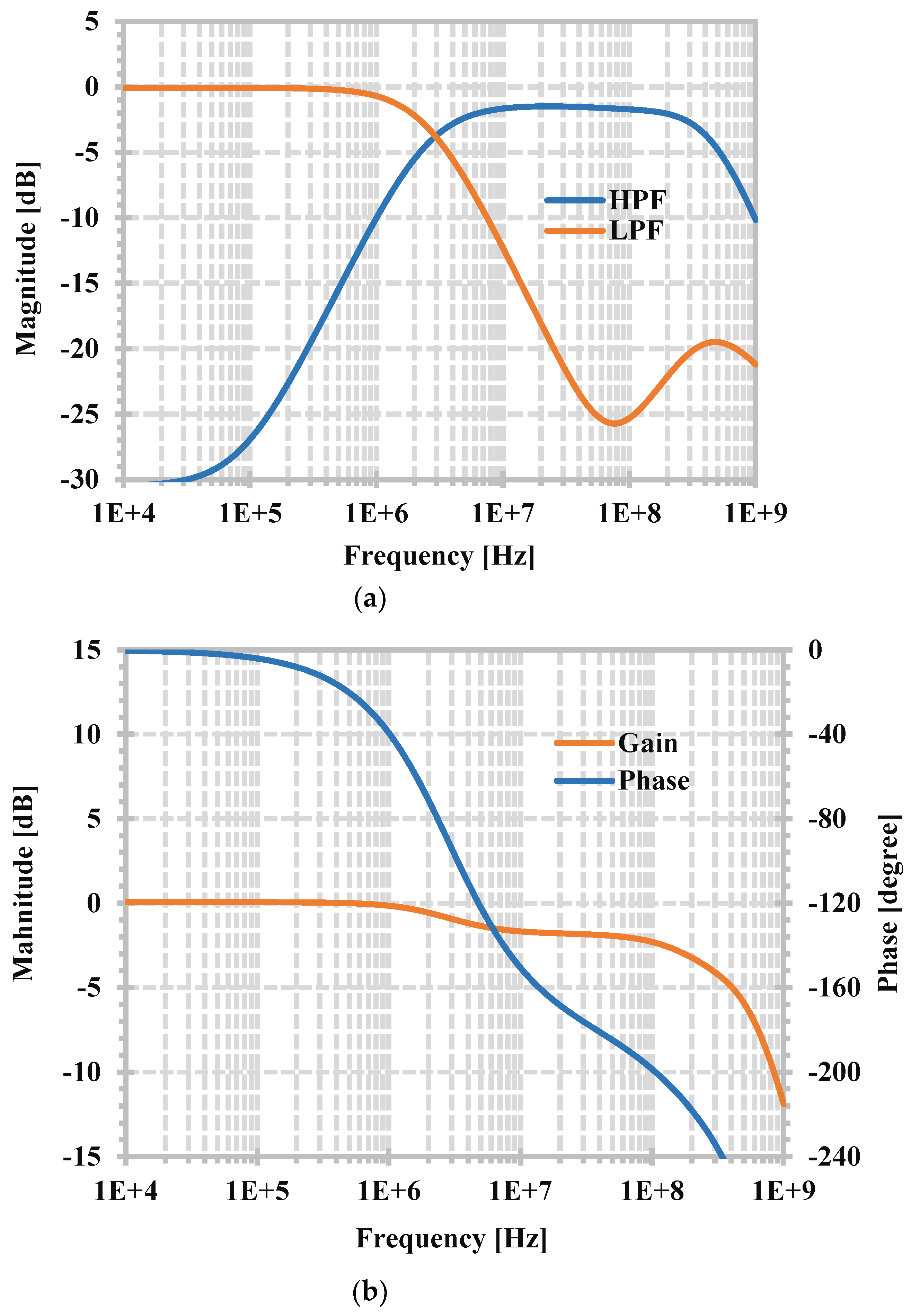
The application of the proposed current-mode active filter to the TIM, TAM, and VM filters in Figure 4 was simulated. Resistors of 10 kΩ were selected for R i n and R o u t . Figure 11 shows the simulated frequency responses of the TIM HPF, LPF, and APF. Figure 12 shows the simulated frequency responses of the TAM HPF, LPF, and APF, and Figure 13 shows the simulated frequency responses of the VM HPF, LPF, and APF. From Figure 11, Figure 12 and Figure 13, it can be confirmed that the proposed first-order CM filter can operate as a mixed-mode universal first-order filter using external resistors without changing the existing CM filter.
In the case of the TAM and VM ( R i n is used for converting the input voltage V i n to the input current I i n ), the magnitude at the passband frequency of the HPF is slightly lower than a unity gain (0 dB). The effect of the intrinsic resistance R x 2 should be considered for applications, i.e., R o u t = R i n + R x 2 . The lower unity gain of magnitude at the passband frequency of the HPF will also slightly affect the magnitude of the APF at a higher frequency than the pole frequency.

4. Experimental Results

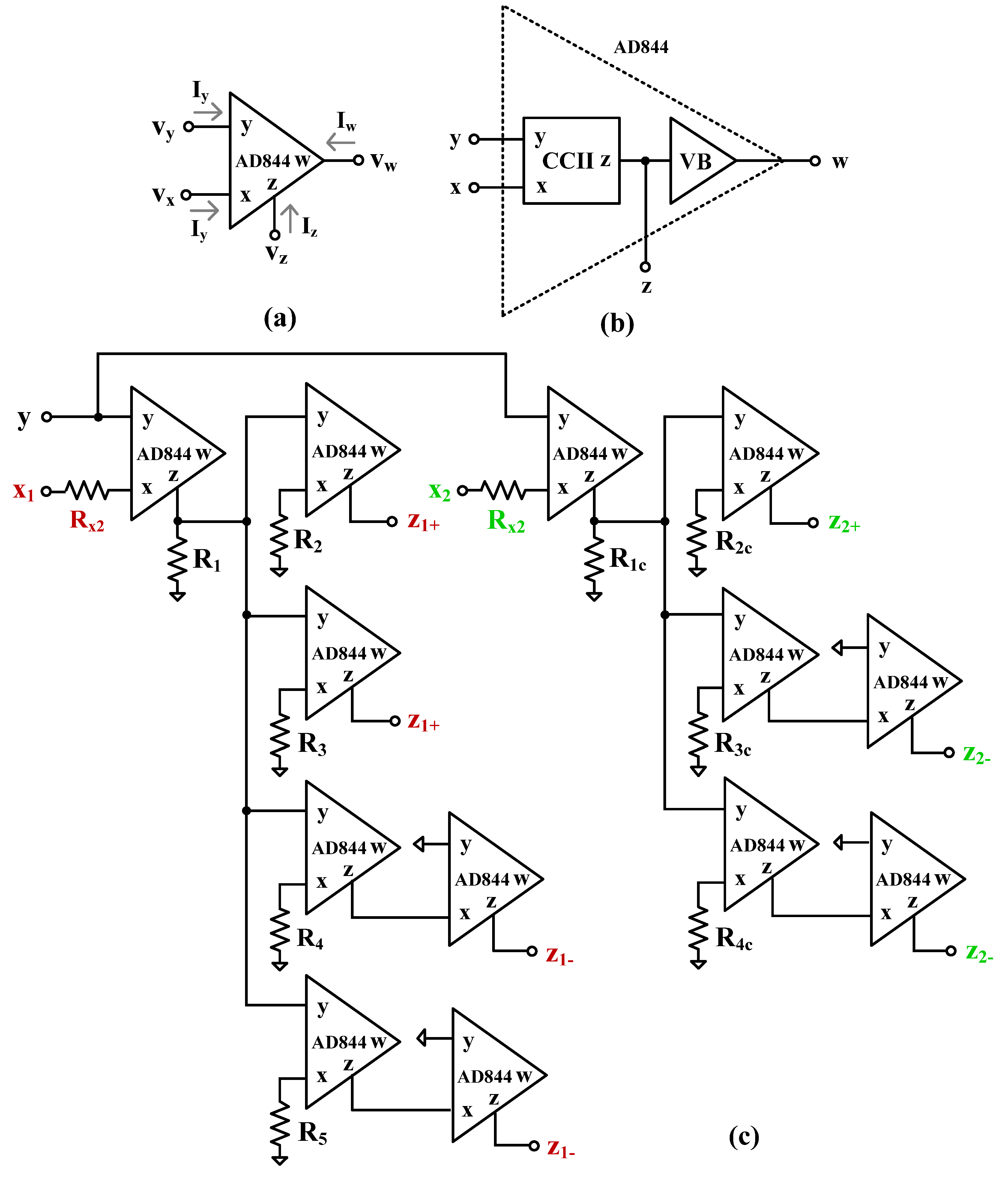
Because the EX-CCCII is not commercially available and the circuit in Figure 2 has not been constructed, an experimental setup was designed using the commercially available AD844 ICs to confirm the theoretical analysis of the proposed filters. The AD844 is a commercially available IC of the CFOA [52], and its symbol is shown in Figure 14a. The CFOA has four terminals and the ideal characteristic can be given by V x = V y , V w = V z , I y = 0 , and I x = I z [53]. It should be noted that the ideal CFOA expresses a voltage buffer between the y- and x-terminals, a current follower between the x- and z-terminals, which is the ideal characteristic of a CCII, and a latter voltage buffer (VB) between the z- and w-terminals. Its internal structure is shown in Figure 14b. To realize the EX-CCCII, only the properties of the CCII are used.
Figure 14c shows the implementation of the EX-CCCII using AD844 ICs. The resistors in the circuit were set as R 1 = R 2 = R 3 = R 4 = R 5 to obtain I x 1 = I z 1 + = I z 1 , and R 1 c = R 2 c = R 3 c = R 4 c to obtain I x 2 = I z 2 + = I z 2 . The resistors R 1 , R 2 , R 3 , R 4 , R 5 , R 1 c , R 2 c , R 3 c , and R 4 c were selected as 1 kΩ. The resistors R x 1 and R x 2 work as intrinsic resistances of the EX-CCCII. The VM filter in Figure 4c was chosen for measurement. The resistances R i n and R o u t were selected as 10 kΩ, and the circuits were supplied by ±5 V. The capacitance C 1 of 27 nF was used.
A photograph of the experimental setup of the first-order VM filter is shown in Figure 15. A Keysight DSOX1204G oscilloscope with a built-in signal generator was used to measure the filter performance. The supply voltage for the AD844 integrated circuits was set to ±5 V.
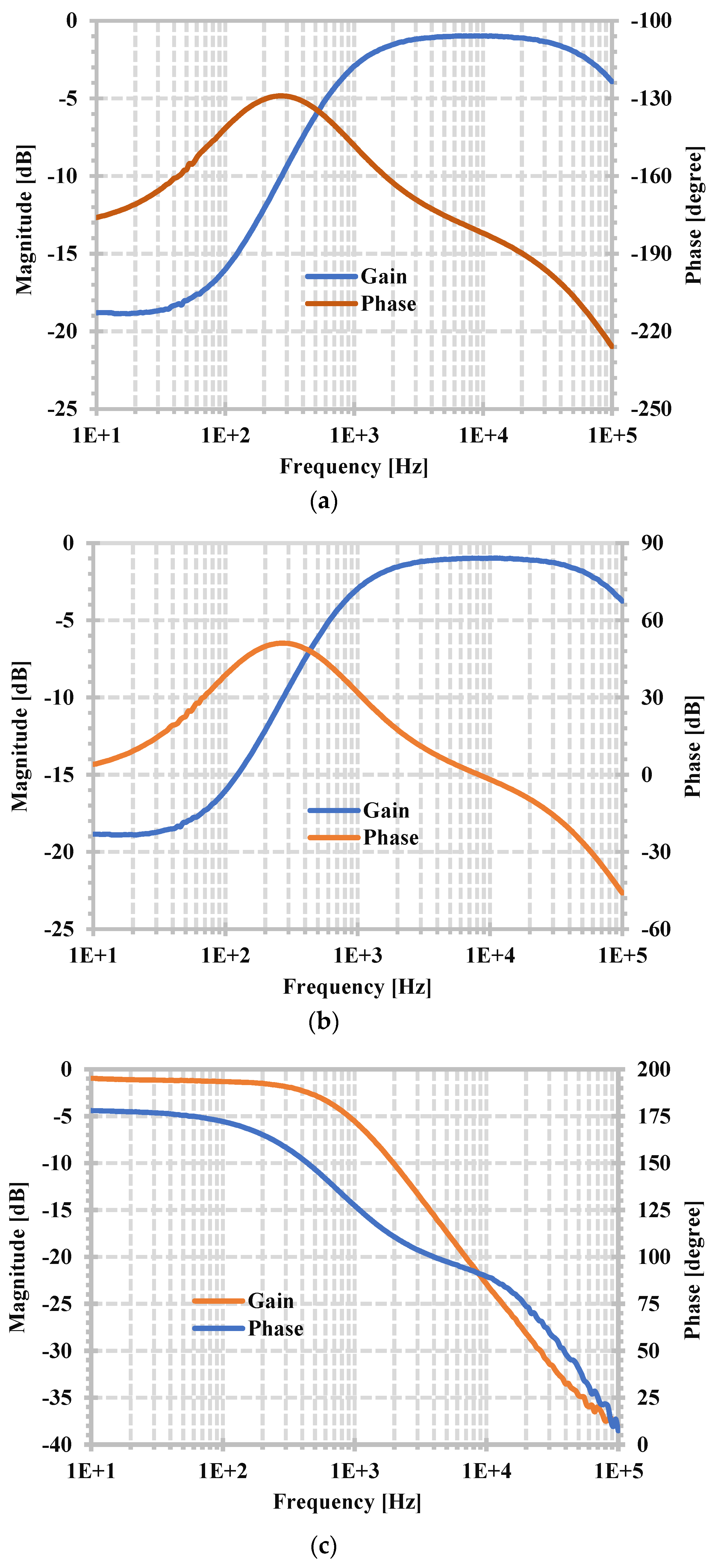
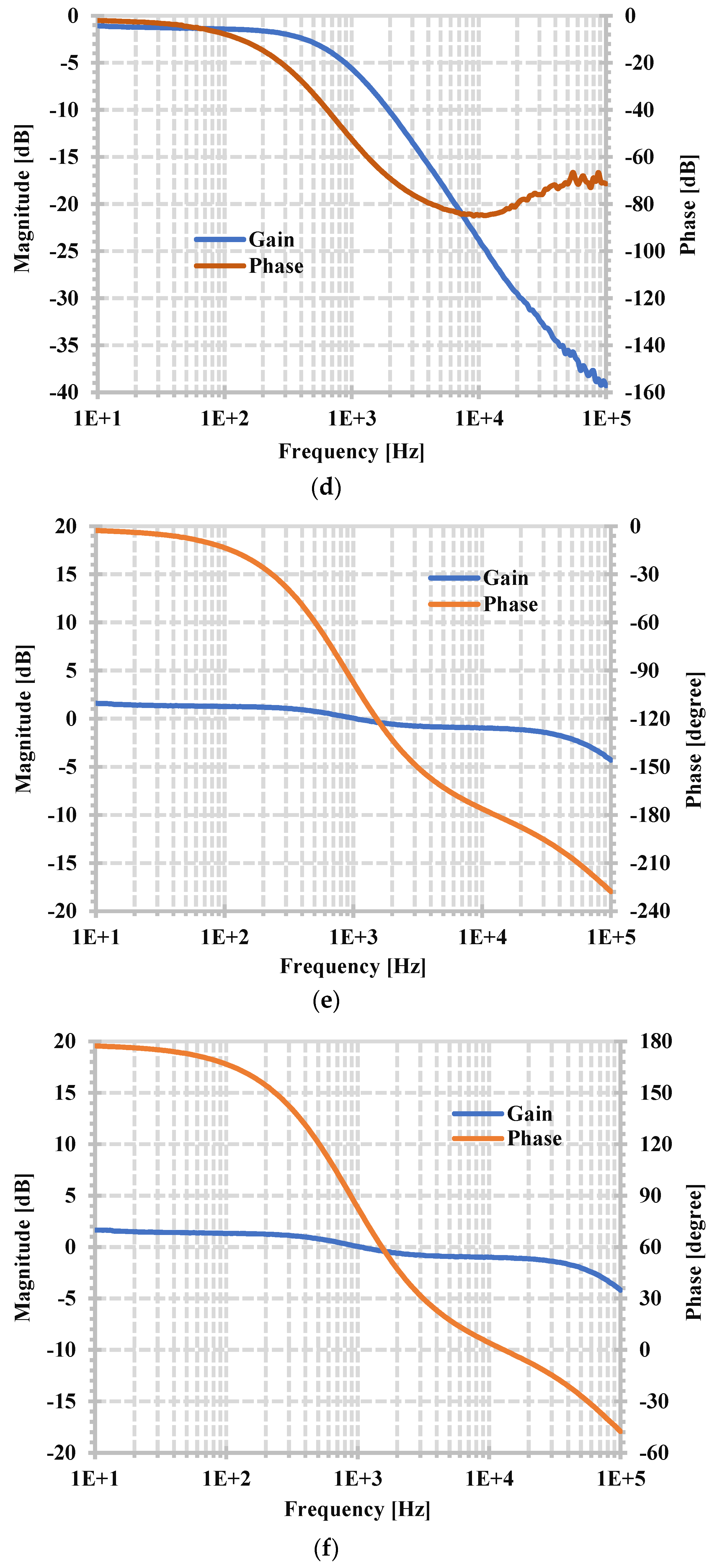
The measured frequency characteristics of the HPF, LPF, and APF with resistor settings R x 1 = R x 2 = 5 kΩ are shown in Figure 16. The measured natural frequency was 0.87 kHz, while the designed pole frequency of the filter was 1.17 kHz.
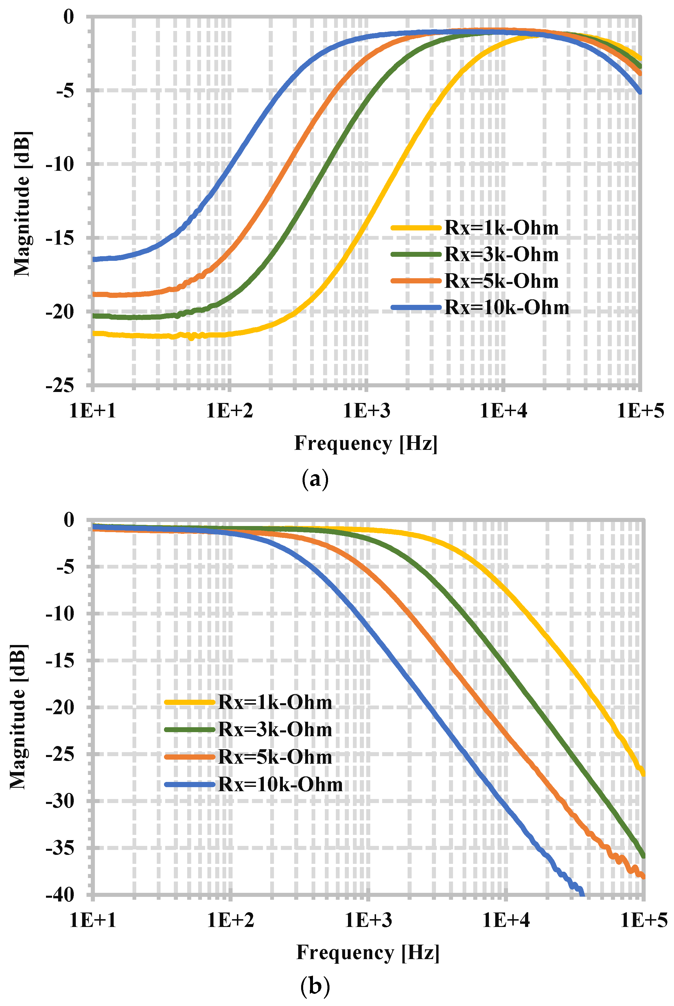
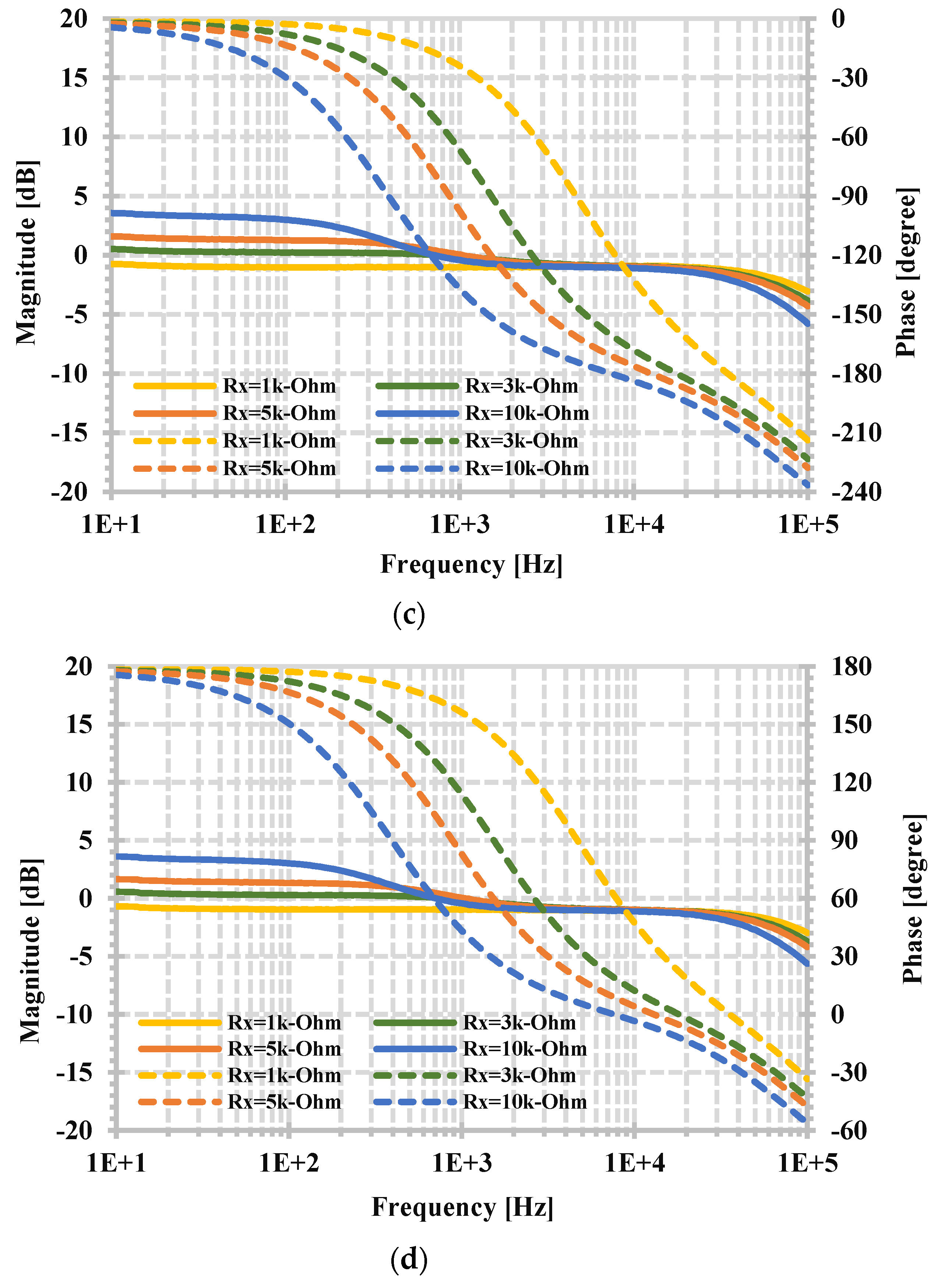
From (7), the pole frequency can be varied by R x ( R x = R x 1 = R x 2 ). Figure 17 shows the measured magnitude frequency responses of the HPF, LPF, and APF when the resistances R x 1 and R x 2 ( R x 1 = R x 2 = R x ) were set to 1 kΩ, 3 kΩ, 5 kΩ, and 10 kΩ. By setting the resistor’s values to 1 kΩ, 3 kΩ, 5 kΩ, and 10 kΩ, the measured pole frequencies were 4.6 kHz, 1.5 kHz, 0.87 kHz, and 0.39 kHz, respectively, while the filter’s designed pole frequencies were, respectively, 5.89 kHz, 1.96 kHz, 1.17 kHz, and 0.58 kHz. This experimental result can be used to confirm the tuning capability of the proposed first-order filter expressed in (7). However, the measured pole frequencies and the designed pole frequencies are slightly different, which is the effect of the IC AD844’s gain error.
Figure 18 shows the measured transient responses of the APF with setting resistances R x 1 = R x 2   = 5 kΩ. This shows the phase difference of about 90 degrees at the pole frequency of the input and output signals. The measured pole frequency was about 0.87 kHz. The experimental results in Figure 16, Figure 17 and Figure 18 show that the proposed VM first-order filter can provide non-inverting and inverting HPFs, LPFs, and APFs. This confirms the functionality of the proposed filter.

5. Conclusions

In this study, a new current-mode first-order versatile active filter using the extra-x second-generation current controlled current conveyor as an active element is proposed. The filter employs one EX-CCCII and one grounded capacitor, which offers the LPF, HPF, and APF in both non-inverting and inverting first-order transfer functions within the same topology, thus obtaining six transfer functions. The circuit offers low-input and high-output impedances that are desirable for current-mode circuits. The pole frequency of all filtering functions can be controlled electronically. The proposed current-mode filter can be applied to work as a TAM, TIM, and VM. SPICE validations using CMOS parameters 0.18 μm confirm the validity of the proposed active filter. The filter uses a supply voltage of ± 0.9 V, consumes 0.558 mW at a pole frequency of 2.85 MHz, and offers a dynamic range of 75.99 dB. The experimental setup using commercially available AD844 integrated circuits was used to confirm the functionality of the new topology. The new circuit can be applied to realize odd-nth-order filters, control systems such as a PID controller, communication systems such as phase/delay equalizers, and a phase lock loop.

Author Contributions

Conceptualization, M.K., F.K. and T.K.; methodology, M.K., F.K. and T.K.; software, M.K. and F.K.; validation, M.K. and F.K.; formal analysis, M.K. and T.K.; investigation, M.K., F.K. and T.K.; resources, M.K.; data curation, M.K. and F.K.; writing—original draft preparation, M.K., F.K. and T.K.; writing—review and editing, M.K., F.K. and T.K.; visualization, M.K. and F.K.; supervision, M.K. and F.K.; project administration, M.K. and F.K.; funding acquisition, M.K. All authors have read and agreed to the published version of the manuscript.

Funding

This work was supported in part by the University of Defence within the Organization Development Project VAROPS.

Institutional Review Board Statement

Not applicable.

Informed Consent Statement

Not applicable.

Data Availability Statement

The original contributions presented in the study are included in the article, further inquiries can be directed to the corresponding author.

Conflicts of Interest

The authors declare no conflicts of interest.

References

  1. Sedra, A.; Smith, K. A Second-Generation Current Conveyor and Its Applications. IEEE Trans. Circuit Theory 1970, 17, 132–134. [Google Scholar] [CrossRef]
  2. Roberts, G.W.; Sedra, A.S. All-Current-Mode Frequency Selective Circuits. Electron. Lett. 1989, 25, 759–761. [Google Scholar] [CrossRef]
  3. Toumazou, C.; Lidgey, F.J.; Haig, D.G. Analogue IC Design: The Current-Mode Approach; Peter Peregrinus: London, UK, 1990. [Google Scholar]
  4. Chiu, W.; Liu, S.I.; Tsao, H.W.; Chen, J.J. CMOS Differential Difference Current Conveyors and Their Applications. IEE Proceeding Circuits Devices Syst. 1996, 143, 91–96. [Google Scholar] [CrossRef]
  5. El-Adawy, A.A.; Soliman, A.M.; Elwan, H.O. A Novel Fully Differential Current Conveyor and Applications for Analog VLSI. IEEE Trans. Circuits Syst.-II 2000, 47, 306–313. [Google Scholar] [CrossRef]
  6. Zeki, A.; Toker, A. The Dual-X Current Conveyor (DXCCII): A New Active Device for Tunable Continuous-Time Filters. Int. J. Electron. 2002, 89, 913–923. [Google Scholar] [CrossRef]
  7. Maheshwari, S. Realization of Simple Electronic Functions Using EXCCII. J. Circuits Syst. Comput. 2017, 26, 1750171. [Google Scholar] [CrossRef]
  8. Maheshwari, S.; Agrawal, D. Cascadable and Tunable Analog Building Blocks Using EX-CCCII. J. Circuits Syst. Comput. 2017, 26, 1750093. [Google Scholar] [CrossRef]
  9. Md Idros, M.F.b.; Abu Hassan, S.F.b. A Design of Butterworth Low Pass Filter’s Layout Basideal Filter Approximation on The Ideal Filter Approximation. In Proceedings of the 2009 IEEE Symposium on Industrial Electronics & Applications, Kuala Lumpur, Malaysia, 4–6 October 2009; pp. 754–757. [Google Scholar] [CrossRef]
  10. Gift, S.J.G. The Application of All-Pass Filters in The Design of Multiphase Sinusoidal Systems. Microelectron. J. 2000, 31, 9–13. [Google Scholar] [CrossRef]
  11. Toker, A.; Ozoguz, S.; Cicekoglu, O.; Acar, C. Current-Mode All-Pass Filters Using Current Differencing Buffered Amplifier and a New High-Q Bandpass Filter Configuration. IEEE Trans. Circuits Syst. II Analog Digit. Signal Process. 2000, 47, 949–954. [Google Scholar] [CrossRef]
  12. Dogan, M.; Yuce, E. A First-Order Universal Filter Including a Grounded Capacitor and Two CFOAs. Analog Integr. Circuits Signal Process. 2022, 112, 379–390. [Google Scholar] [CrossRef]
  13. Kumari, S.; Nand, D. DDCC-Based MISO Type Voltage-Mode First-Order Universal Filter. In Proceedings of the 2022 2nd International Conference on Intelligent Technologies (CONIT), Hubli, India, 24–26 June 2022; pp. 1–6. [Google Scholar] [CrossRef]
  14. Singh, P.; Varshney, V.; Kumar, A.; Nagaria, R.K. Electronically Tunable First Order Universal Filter Based on CCDDCCTA. In Proceedings of the 2019 IEEE Conference on Information and Communication Technology, Allahabad, India, 6–8 December 2019; pp. 1–6. [Google Scholar] [CrossRef]
  15. Jaikla, W.; Talabthong, P.; Siripongdee, S.; Supavarasuwat, P.; Suwanjan, P.; Chaichana, A. Electronically Controlled Voltage Mode First Order Multifunction Filter Using Low-Voltage Low-Power Bulk-Driven OTAs. Microelectron. J. 2019, 91, 22–35. [Google Scholar] [CrossRef]
  16. Jaikla, W.; Buakhong, U.; Siripongdee, S.; Khateb, F.; Sotner, S.; Silapan, P.; Suwanjan, P.; Chaichana, A. Single Commercially Available IC-Based Electronically Controllable Voltage-Mode First-Order Multifunction Filter with Complete Standard Functions and Low Output Impedance. Sensors 2021, 21, 7376. [Google Scholar] [CrossRef] [PubMed]
  17. Barile, G.; Safari, L.; Pantoli, L.; Stornelli, V.; Ferri, G. Electronically Tunable First Order AP/LP and LP/HP Filter Topologies Using Electronically Controllable Second Generation Voltage Conveyor (CVCII). Electronics 2021, 10, 822. [Google Scholar] [CrossRef]
  18. Duangmalai, D.; Suwanjan, P. The Voltage-Mode First Order Universal Filter Using Single Voltage Differencing Differential Input Buffered Amplifier with Electronic Controllability. Int. J. Electr. Comput. Eng. 2022, 12, 1308–1323. [Google Scholar] [CrossRef]
  19. Singh, P.; Nagaria, R.K. Voltage Mode and Trans-Admittance Mode First-Order Universal Filters Employing DV-EXCCCII. Aust. J. Electr. Electron. Eng. 2022, 19, 396–406. [Google Scholar] [CrossRef]
  20. Dogan, M.; Yuce, E.; Dicle, Z. CFOA-Based First-Order Voltage-Mode Universal Filters. AEU-Int. J. Electron. Commun. 2023, 161, 154550. [Google Scholar] [CrossRef]
  21. Khateb, F.; Kumngern, M.; Kulej, T. 0.5-V Nano-Power Voltage-Mode First-Order Universal Filter Based on Multiple-Input OTA. IEEE Access 2023, 11, 49806–49818. [Google Scholar] [CrossRef]
  22. Kumngern, M.; Khateb, F.; Kulej, T.; Steffan, P. 0.3-V Voltage-Mode Versatile First-Order Analog Filter Using Multiple-Input DDTAs. Sensors 2023, 23, 5945. [Google Scholar] [CrossRef] [PubMed]
  23. Li, Y.-A. A series of new circuits based on CFTAs. AEU-Int. J. Electron. Commun. 2012, 66, 587–592. [Google Scholar] [CrossRef]
  24. Herencsar, N.; Lahiri, A.; Koton, J.; Vrba, K. First-Order Multifunction Filter Design Using Current Amplifiers. In Proceedings of the 2016 39th International Conference on Telecommunications and Signal Processing (TSP), Vienna, Austria, 27–29 June 2016; pp. 279–282. [Google Scholar] [CrossRef]
  25. Kumar, A.; Paul, S.K. Current Mode First Order Universal Filter and Multiphase Sinusoidal Oscillator. AEU-Int. J. Electron. Commun. 2017, 81, 37–49. [Google Scholar] [CrossRef]
  26. Chaturvedi, B.; Mohan, J.; Jitender; Kumar, A. A Novel Realization of Current-Mode First Order Universal Filter. In Proceedings of the 2019 6th International Conference on Signal Processing and Integrated Networks (SPIN), Noida, India, 7–8 March 2019; pp. 623–627. [CrossRef]
  27. Horng, J.-W.; Wu, C.-M.; Zheng, J.-H.; Li, S.-Y. Current-Mode First-Order Highpass, Lowpass, And Allpass Filters Using Two ICCIIs. In Proceedings of the 2020 IEEE International Conference on Consumer Electronics-Taiwan (IC-CE-Taiwan), Taoyuan, Taiwan, 28–30 September 2020; pp. 1–2. [Google Scholar] [CrossRef]
  28. Yucel, F. A DVCC-Based Current-Mode First-Order Universal Filter. J. Circuits Syst. Comput. 2021, 30, 2150305. [Google Scholar] [CrossRef]
  29. Yuce, E.; Minaei, S. A New First-Order Universal Filter Consisting of Two ICCII+s and a Grounded Capacitor. AEU-Int. J. Electron. Commun. 2021, 137, 153802. [Google Scholar] [CrossRef]
  30. Raj, A.; Bhaskar, D.R.; Senani, R.; Kumar, P. Extension of Recently Proposed Two-CFOA-GC All Pass Filters to The Realisation of First Order Universal Active Filters. AEU-Int. J. Electron. Commun. 2022, 146, 154119. [Google Scholar] [CrossRef]
  31. Herencsar, N.; Koton, J.; Sagbas, M.; Ayten, U.E. New Tunable Resistorless CM First-Order Filter Based on Single CBTA and Grounded Capacitor. In Proceedings of the 2016 IEEE 59th International Midwest Symposium on Circuits and Systems (MWSCAS), Abu Dhabi, United Arab Emirates, 16–19 October 2016; pp. 1–4. [Google Scholar] [CrossRef]
  32. Safari, L.; Yuce, E.; Minaei, S. A New ICCII Based Resistor-Less Current-Mode First-Order Universal Filter with Electronic Tuning Capability. Microelectron. J. 2017, 67, 101–110. [Google Scholar] [CrossRef]
  33. Chaturvedi, B.; Kumar, A.; Mohan, J. Low Voltage Operated Current-Mode First-Order Universal Filter and Sinusoidal Oscillator Suitable for Signal Processing Applications. AEU-Int. J. Electron. Commun. 2019, 99, 110–118. [Google Scholar] [CrossRef]
  34. Chaturvedi, B.; Mohan, J.; Jitender; Kumar, A. Resistorless Realization of First-Order Current Mode Universal Filter. Radio Sci. 2020, 55, e2019RS006932. [Google Scholar] [CrossRef]
  35. Kumar, A.; Kumar, S.; Elkamchouchi, D.H.; Urooj, S. Fully Differential Current-Mode Configuration for the Realization of First-Order Filters with Ease of Cascadability. Electronics 2022, 11, 2072. [Google Scholar] [CrossRef]
  36. Chaturvedi, B.; Kumar, A. Electronically Tunable First-Order Filters and Dual-Mode Multiphase Oscillator. Circuits Syst. Signal Process. 2019, 38, 2–25. [Google Scholar] [CrossRef]
  37. Rohilla, K.; Pushkar, K.L.; Kumar, R.; Raj, A. Resistorless First-Order Universal Filter Structures Employing OTAs with Independent Controllability of Gain and Pole Frequency. IETE J. Res. 2022, 70, 756–776. [Google Scholar] [CrossRef]
  38. Kumngern, M.; Jongchanachavawat, W.; Phatsornsiri, P.; Wongprommoon, N.; Khateb, F.; Kulej, T. Current-Mode First-Order Versatile Filter Using Translinear Current Conveyors with Controlled Current Gain. Electronics 2023, 12, 2828. [Google Scholar] [CrossRef]
  39. Chaturvedi, B.; Mohan, J.; Gupta, S.N. First Order Mixed Mode MOS-C All-Pass Frequency Selective Analog Network with Electronic Tuning. Trends Sci. 2022, 19, 4616. [Google Scholar] [CrossRef]
  40. Raj, A. Mixed-Mode Electronically-Tunable First-Order Universal Filter Structure Employing Operational Transconductance Amplifiers. J. Circuits Syst. Comput. 2022, 31, 2250234. [Google Scholar] [CrossRef]
  41. Bhaskar, D.R.; Raj, A.; Rajb, S.; Kumar, P. CFOA-Based Simple Mixed-Mode First-Order Universal Filter Configurations. Int. J. Circuit Theory Appl. 2022, 50, 2631–2641. [Google Scholar] [CrossRef]
  42. Roongmuanpha, N.; Likhitkitwoerakul, N.; Fukuhara, M.; Tangsrirat, W. Single VDGA-Based Mixed-Mode Electronically Tunable First-Order Universal Filter. Sensors 2023, 23, 2759. [Google Scholar] [CrossRef] [PubMed]
  43. Perumal, S.; Faseehuddin, M.; Kukker, A.; Shireen, S.; Tangsrirat, W. Minimum Component Truly Mixed Mode First Order Universal Filter Employing EXCCTA. Inf. MIDEM 2023, 53, 177–189. [Google Scholar] [CrossRef]
  44. Maheshwari, S. Current Conveyor All-Pass Sections: Brief Review and Novel Solution. Sci. World J. 2013, 2013, 429391. [Google Scholar] [CrossRef]
  45. Maheshwari, S. Tuning Approach for First-Order Filters and New Current-Mode Circuit Example. IET Circuits Devices Syst. 2018, 12, 478–485. [Google Scholar] [CrossRef]
  46. Agrawal, D.; Maheshwari, S. An Active-C Current-Mode Universal First-Order Filter and Oscillator. J. Circuits Syst. Comput. 2019, 28, 1950219. [Google Scholar] [CrossRef]
  47. Agrawal, D.; Tripathi, S.K.; Reddy, N.S.; Reddy, M.V.; Shoaib, P.M. Design a Configurable First Order Universal Filter Using a Single EX-CCCII. Russ. Microelectron. 2024, 53, 290–296. [Google Scholar] [CrossRef]
  48. Mohan, J.; Chaturvedi, B.; Jitender. CMOS Compatible First-Order Current Mode Universal Filter Structure and Its Possible Tunable Variant. J. Circuits Syst. Comput. 2022, 31, 2250242. [Google Scholar] [CrossRef]
  49. Lee, C.-N. Fully Cascadable Mixed-Mode Universal Filter Biquad Using DDCCs and Grounded Passive Components. J. Circuits Syst. Comput. 2011, 20, 607–620. [Google Scholar] [CrossRef]
  50. Agrawal, D.; Maheshwari, S. High-Performance Electronically Tunable Analog Filter Using a Single EX-CCCII. Circuits Syst. Signal Process. 2021, 40, 1127–1151. [Google Scholar] [CrossRef]
  51. Riewruja, V.; Anuntahirunrat, K.; Surakampontorn, W. A Class AB CMOS Square-Rooting Circuit. Int. J. Electron. 1998, 85, 55–60. [Google Scholar] [CrossRef]
  52. AD844: 60 MHz, 2000 V/s, Monolithic Op-amp with Quad Low Noise Data Sheet (Rev. G). May 2017. Available online: www.linear.com (accessed on 1 December 2020).
  53. Bhaskar, D.R.; Raj, A.; Senani, R. Three new CFOA-based SIMO-type universal active filter configurations with unrivalled features. AEU Int. J. Electron. Commun. 2022, 153, 154285. [Google Scholar] [CrossRef]
Figure 1. EX-CCCII: (a) symbol, (b) equivalent circuit.
Applsci 14 07396 g001
Figure 2. CMOS structure of the EX-CCCII.
Applsci 14 07396 g002
Figure 3. Proposed current-mode first-order versatile active filter using EX-CCCII.
Applsci 14 07396 g003
Figure 4. Proposed mixed-mode active filter: (a) TIM, (b) TAM, and (c) VM.
Applsci 14 07396 g004aApplsci 14 07396 g004b
Figure 5. The intrinsic resistance R x against the setting current.
Applsci 14 07396 g005
Figure 6. Simulated frequency responses of non-inverting (a) HPF, (b) LPF, and (c) APF.
Applsci 14 07396 g006
Figure 7. Simulated frequency responses with different setting currents for (a) HPF, (b) LPF, and (c) APF.
Applsci 14 07396 g007aApplsci 14 07396 g007b
Figure 8. Simulated frequency responses of HPF, LPF, and APF with different parameter variations: (a) process, (b) supply voltage, and (c) temperature.
Applsci 14 07396 g008aApplsci 14 07396 g008b
Figure 9. The linearity of the LPF: (a) input and output waveform for a THD of 1.09%, and (b) a THD with different input amplitudes.
Applsci 14 07396 g009
Figure 10. The equivalent output current noise of the LPF.
Applsci 14 07396 g010
Figure 11. Simulated frequency responses of the TIM filter: (a) HPF, LPF, and (b) APF.
Applsci 14 07396 g011
Figure 12. Simulated frequency responses of the TAM filter: (a) HPF, LPF, and (b) APF.
Applsci 14 07396 g012
Figure 13. Simulated frequency responses of the VM filter: (a) HPF, LPF, and (b) APF.
Applsci 14 07396 g013
Figure 14. AD844 IC: (a) symbol, (b) internal structure, and (c) realization of the EX-CCCII using the AD844 ICs.
Applsci 14 07396 g014
Figure 15. First-order VM filter using the AD844-based EX-CCCII: (a) experimental setup and (b) close-up image of the circuit.
Applsci 14 07396 g015
Figure 16. Measured frequency responses: HPF (a) V o 1 and (b) V o 2 ; LPF (c) V o 3 and (d) V o 4 ; APF (e) V o 1 + V o 4 (AP+) and (f) V o 3 + V o 2 (AP−).
Applsci 14 07396 g016aApplsci 14 07396 g016b
Figure 17. Measured frequency responses with different values of Rx for the (a) HPF, (b) LPF, and APF: (c) V o 1 + V o 4 (AP+), and (d) V o 3 + V o 2 (AP−).
Applsci 14 07396 g017aApplsci 14 07396 g017b
Figure 18. Measured transient responses of APFs showing phase differences of the input and output signals for (a) AP+ ( V o 1 + V o 4 ) and (b) AP− ( V o 3 + V o 2 ).
Applsci 14 07396 g018aApplsci 14 07396 g018b
Table 1. Aspect ratios of the MOS transistors of the EX-CCCII’s structure.
TransistorW/L (µm/µm)
M1–M35/0.36
M4–M615/0.36
Mb, M7–M183/0.36
M19–M306/0.36
Table 2. Simulated specifications of the EX-CCCII.
ParametersValue
Technology0.18 µm CMOS
Power supply±0.9 V
DC voltage range±200 mV
DC current range ±200 μA
Voltage gain Vx/Vy0.964
Current gain (Iz+/Ix)1.01
Current gain (Iz−/Ix)1.04
Bandwidth (−3 dB) @ Iset = 20 µA
Voltage follower (Vx/Vy)2 GHz
Current follower (Iz+/Ix)61.46 MHz
Current follower (Iz−/Ix)61.46 MHz
THD [Vy = 200 mV @ 10 kHz]0.69%
PSRR+32.82 dB
PSRR−37.67 dB
Parasitic parameters @ Iset = 20 µA
- Ry, Cy104 kΩ, 0.14 pF
- Rx, Lx1.81 kΩ, 62 nH
- Rz, Cz221.35 kΩ, 75.68 fF
Power consumption @ Iset = [10–50] µA[0.29–1.24] mW
Table 3. Properties comparison of this work with those of some first-order universal filters.
FactorProposed[32][33][42][43][47]
Number of active devices1-EX-CCCII2-ICCII1-DXCCTA1-EXCCTA1-VDGA1-EX-CCCII
RealizationCMOS structure and commercial ICCMOS structureCMOS structure and commercial ICCMOS structure and commercial ICCMOS structure and commercial ICCMOS structure
Number of capacitors1-C1-C1-C1-C1-C1-C
Passive/active resistor-1-MOST-4-MOST1-R-
Type of filterSIMOSIMOSIMOSIMOMIMOSISO
Operation modeCMCMCMMMMMVM
Number of offered responses66312-MM
3-CM
12-MM
3-CM
3
All grounded capacitorsYesNoYesYesYes (CM)Yes
Low-input and high-output impedancesYesNoYesYesNo-
Electronic   control   of   ω o YesYesYesYesYesYes
Simulated power supply (V)±0.9±0.75±1.25±1.25±0.9±0.5
Pole frequency (MHz)2.852.61016.231.594.5
Simulated power dissipation (mW)0.5584.081.75-1.31-
Total harmonic distortion (%)1.09@120 μA<1.5@90 μApp--0.38@20 μA (Exp.)-
Dynamic range75.99-----
Verification of resultSim./Exp. *Sim.Sim./Exp. *Sim./Exp. *Sim./Exp. *Sim.
Note: MOST = MOS Transistor, MM = Mixed-Mode, MIMO = Multiple-Input Multiple-Output, SISO = Single-Input Single-Output, * = it was verified with COTS components.
Disclaimer/Publisher’s Note: The statements, opinions and data contained in all publications are solely those of the individual author(s) and contributor(s) and not of MDPI and/or the editor(s). MDPI and/or the editor(s) disclaim responsibility for any injury to people or property resulting from any ideas, methods, instructions or products referred to in the content.