Article

An Assessment of the Mechanical Deformation Behavior of Three Different Clear Aligner Materials: A Digital Image Correlation Analysis

by
Nicolae Daniel Olteanu
1,
Camelia Szuhanek
2,*,
Sorana Nicoleta Rosu
1,*,
Dragos Florin Chitariu
3,
Nicolae Seghedin
3,
Tinela Panaite
1,
Amalia Casalean
2 and
Irina Nicoleta Zetu
1
1
Department of Oral and Maxillofacial Surgery, Faculty of Dental Medicine, “Grigore T. Popa” University of Medicine and Pharmacy from Iasi, 16 Universitatii Str., 700115 Iasi, Romania
2
Ortho-Center Research Center, Department of Orthodontics, Faculty of Dental Medicine, “Victor Babeş” University of Medicine and Pharmacy Timisoara, 9 No., Revolutiei Bv., 300041 Timişoara, Romania
3
Faculty of Machine Manufacturing and Industrial Management, “Gheorghe Asachi” Technical University of Iaşi, 700050 Iasi, Romania
*
Authors to whom correspondence should be addressed.
Appl. Sci. 2024, 14(17), 7496; https://doi.org/10.3390/app14177496
Submission received: 31 July 2024 / Revised: 21 August 2024 / Accepted: 22 August 2024 / Published: 24 August 2024
(This article belongs to the Special Issue Orthodontic Treatment: Current State and Future Possibilities)

Abstract

:
Introduction: The present study aimed to investigate the deformation behavior of three different clear aligner systems, CA® Pro+ Clear Aligner (Scheu Dental, Iserlohn, Germany), Taglus Premium (Taglus Company, Mumbai, India), and Spark Trugen (Ormco Corp., Orange, CA, USA), under compression testing, using the digital image correlation (DIC) technique. Materials and Methods: A total of 15 patients were treated with each of the three aligner systems, resulting in 45 sets of aligners. Each aligner set was fixed on the 3D-printed dental arches and then in an articulator. Then, the samples were subjected to occlusal forces using a purpose-built test stand to allow for controlled force application and precise displacement determination. The DIC technique was used for capturing the deformation behavior, providing detailed strain and displacement fields. Statistical analysis was performed using one-way ANOVA and Bonferroni post hoc tests with a significance of 0.05. Results: The results indicate that the Spark system exhibited the most substantial rigid displacement. Furthermore, the elastic deformation values of the Spark and Taglus systems were significantly higher than those of the CA Pro+ system (p > 0.05). Conclusions: The Spark Trugen clear aligner system demonstrated a lower stability to rigid displacement and elastic deformation under compression testing compared to the Scheu CA® Pro+ Clear Aligner and Taglus Premium. All three tested clear aligner systems showed an increased resistance to elastic displacement and rigid deformation in the mandibular arch.

1. Introduction

In recent years, clear aligners have revolutionized the field of orthodontics, providing an aesthetically pleasing and comfortable alternative to traditional braces. However, understanding the mechanical deformation behavior of aligners is crucial for optimizing their design and performance [1].
Clear aligners, typically made from thermoplastic polymers, work by applying controlled forces to teeth, gradually moving them into the desired position [2]. Unlike braces, aligners are removable and nearly invisible, which has contributed to their growing popularity. Despite their advantages, the success of aligners hinges on their mechanical behavior, particularly their ability to withstand deformation while delivering consistent forces over the treatment period [1,2].
Clear aligner treatment requires periodic refinements which are undesirable, costly, and unrecyclable. One of the reasons for refinements is the material from which the aligner is made. Polyethylene terephthalate glycol (PET-G) is currently the most widely used clear aligner material [3]. Polymers with shape memory properties for direct 3D printing, such as TC-85, a photocurable resin, have been proposed as new clear aligner materials [4]. New aligner materials seek to apply a constant force over a considerable period of time, with increased elasticity, strength, and transparency, and a more precise fit [1]. However, the force exerted by clear aligners decreases in 1–3 days due to the stress relaxation of the viscoelastic aligner materials. Clear aligners deform and wear in spots where attachments are fixed [3,5]. Temperature, oral functional and parafunctional forces induced by chewing, talking, drinking, swallowing, bruxism, and unilateral mastication may also modify the mechanical behavior of aligner materials [6]. Aligners made of the same material but printed on different 3D printers show significantly different mechanical properties [7].
The most suitable mechanical properties of aligner materials are characterized by stiffness, high yield strength, and a flat relaxation curve with low-stress relaxation levels [8]. Aligners with high stiffness are difficult to insert and remove, whereas aligners with decreased elasticity may not provide the force necessary to move teeth [9]. The initial removal of clear aligners is believed to make the material return to its initial shape and become wider transversally and shorter longitudinally [10].
The following finite element analysis and experimental methods were used for studying the mechanical behavior and the forces exerted by clear aligner materials [11], expressed as measurements of elasticity, strength, stiffness, and shape memory: the three-point bending test [3], compression tests such as tensile yield stress, stress relaxation, creep recovery, elastic modulus, and Young’s modulus tests [4,8,9], Martens hardness test, instrumented indentation testing [12], the U-shape bending test and the shape recovery ratio [4], von Mises stress distribution in Finite Element Analysis (FEA)/Finite Element Modeling (FEM) [10,11,13], the RSA3 Dynamic Mechanical Analyzer (Texas Instruments, Dallas), and the INSTRON Universal Testing System (Instron Corp, Wilmington/Norwood) [8,9]. Clear aligner wear expressed as microcracks, abrasion, and changes in clear aligner thickness were assessed by scanning electron microscopy, energy dispersive X-ray microanalysis, 3D models of clear aligners at different reference occlusal points, and the software Geomagic Qualify 2013 (3D Systems, Rock Hill, SC, USA). The behavior of the materials used in dentistry can also be assessed by the DIC (Digital Image Correlation) technique, which consists of a contact-free optical method for measuring deformations, motions, and changes in the shape of object surfaces [6].
The aim of the present study was to assess the deformation behavior of three different aligner systems—CA® Pro+ Clear Aligner (Scheu Dental, Iserlohn, Germany), Taglus Premium (Taglus Company, Mumbai, India), and Spark Trugen (Ormco Corp., Orange, CA, USA)—through a compression method by the digital image correlation (DIC) technique. The null hypothesis states that no differences in deformation behavior are recorded between the three aligner systems.

2. Materials and Methods

The study was conducted in accordance with the requirements of the Declaration of Helsinki and the rules imposed by the Research Ethics Committee of “Grigore T. Popa” University of Medicine and Pharmacy of Iasi, Romania (approval no. 56/12.03.2021). In addition, the patients were informed and consented to participate in the study by signing an informed consent.

2.1. Sample Preparation

The sample size was calculated using G*Power software version 3.1 (Heinrich-Heine University, Dusseldorf, Germany) with an alpha error of 0.05, an effect size of 0.5, and a power of the study of 0.8. The recommended minimum number of samples to be used in the study was 42.
The present study was conducted on a total of 15 patients, aged between 20 and 30 years, who came to the Pediatric Dentistry clinic, Orthodontics Department of “Grigore T. Popa” University of Medicine and Pharmacy, with an orthodontic diagnosis of dento-maxillary disharmony of Angle class I with crowding. After the clinical examination, diagnosis, and indication for orthodontic treatment with aligners, each of the 15 patients was fitted with a pair of aligners (upper and lower jaws) from each of the three tested systems. Therefore, the resulting total number of 45 pairs of study samples were divided into 3 groups corresponding to the used aligner system. The distribution of the samples and the material compositions are presented in Table 1.
The design of a clear aligner started with a digital dental record performed with a dedicated intraoral scan (MEDIT- I 500 scanner, Medit Corp., Seoul, Republic of Korea). The scan was then processed by the 3Shape OrthoAnalyzer® software (TRIOS-3Shape, Copenhagen, Denmark) or Approver (Spark ORMCO, Ormco Corp., Orange, CA, USA), which provided an accurate 3D reconstruction of the teeth and allowed for the 3D Setup to be performed. During this step, the orthodontist and the dental technician planned the dental movement and the final result. The virtual 3D reconstruction allowed them to print a resin cast and then thermoform and process the aligner materials accordingly.

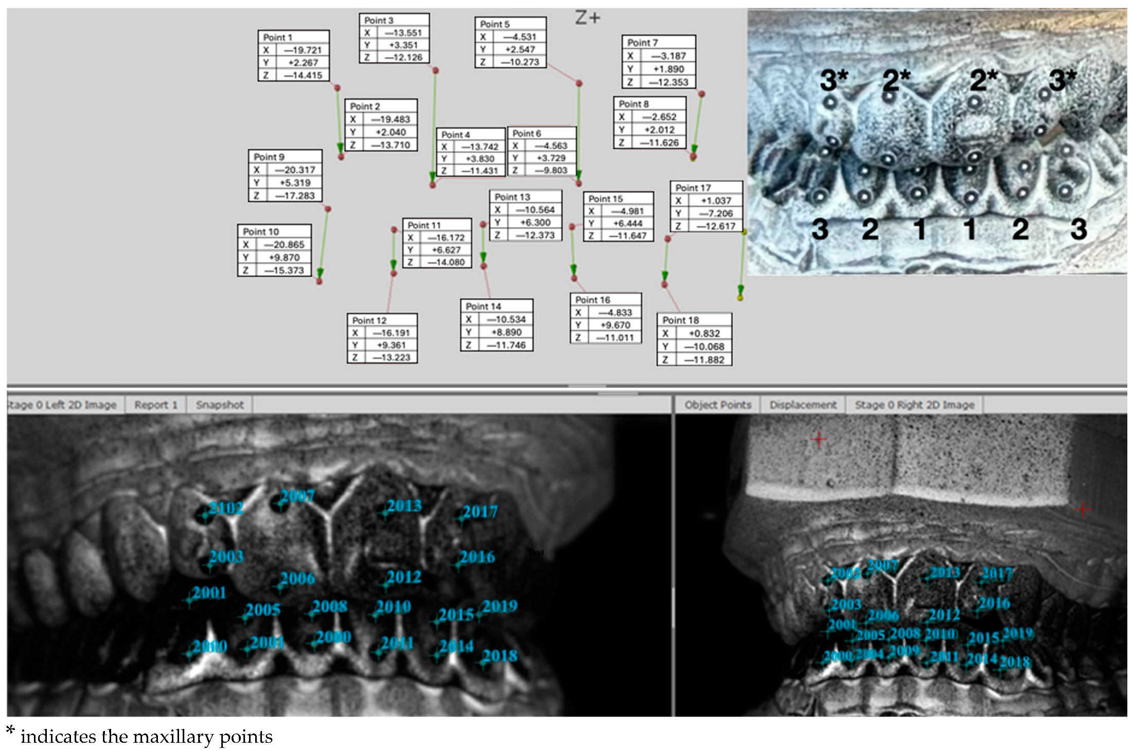
2.2. Deformation Behavior Testing

To investigate the deformation behavior, the clear aligners were subjected to occlusal forces using a purpose-made test stand developed in order to allow for controlled force application and to precisely determine the displacements of the aligners. The present study evaluated the following three different aligner materials and systems: CA® Pro+ Clear Aligner (Scheu Dental, Iserlohn, Germany), Taglus Premium (Taglus Company, Mumbai, India), and Spark Trugen (Ormco Corp., Orange, CA, USA).
The clear aligners were placed on 3D-printed dental arches, which in turn were fixed on hard resin dental casts that were fixed in a dental articulator. Thus, the mechanical hinged fixture could simulate the bite closure movement.
The lower part of the articulator (the lower jaw) was rigidly fixed on the base plate of the stand. In order to use the digital image correlation (DIC) method, markers were placed on the gingival and incisal part of the aligner for the upper and lower incisors as well as for lower incisors and canines on the frontal plane of the aligners (Figure 1).
The loading force of up to 500 N was applied, equivalent to the human biting force, the maximum molar occlusal force. Muscle activity during chewing was assessed to be normal during clear aligner use. The average magnitude of the biting force of a human is nearly 500 N [13]. The forces were measured directly using a S9 force transducer (produced by Hottinger Baldwin Messtechnik, HBM GmbH, Darmstadt, Germany) placed directly on the upper hard resin dental cast model. Force data acquisition was performed by Spider 8 PC measurement electronics (produced by Hottinger Baldwin Messtechnik, HBM GmbH, Darmstadt, Germany) linked to a PC running a Catman Easy/AP software version 2.2.
The deformation behavior of the materials was assessed using a digital image correlation (DIC) system. This is a contactless and non-destructive measurement technique that can compute 2D or 3D coordinates from an image series recorded with a stereo camera. By interpreting local displacements between the 2D or 3D coordinates, strain values and strain rates can be calculated. The DIC method uses reference images captured by the left and the right camera to determine the 3D coordinates of various points that will be analyzed, by subtracting the 3D coordinates from all recorded stages over time from the 3D coordinates of the reference stage which led to 3D displacement values. Before carrying out the measurements, the calibration procedure was performed in order for the possible measurement errors to remain low.
The measurement of the displacements and deformations was performed through the DIC system ARAMIS 3D 12M Camera (Carl Zeiss, Jena, Germany) running the PONTOS software version v6.3.1-1 (PONTOS Software GmbH, Jena, Germany). PONTOS Live is based on the triangulation principle and analyses components of different sizes—from a few millimeters to a few meters—point by point, regardless of the material. The DIC hardware system parameters are presented in Table 2.
Considering the field of view, calibration was performed, resulting in a measuring area of 420 × 330 × 300 mm. The software was able to provide the average value of the 3D coordinates (X, Y and Z) of each tracker placed, and further 3D displacements could then be calculated.
The deformation of each of the three aligner materials was measured using trackers placed in the same points. In our research, each of the three aligner materials was tested on the same test stand and using the same load value. The 3D displacements were measured during loading, and the rigid displacements and elastic deformation on each axis were determined.

2.3. Statistical Analysis
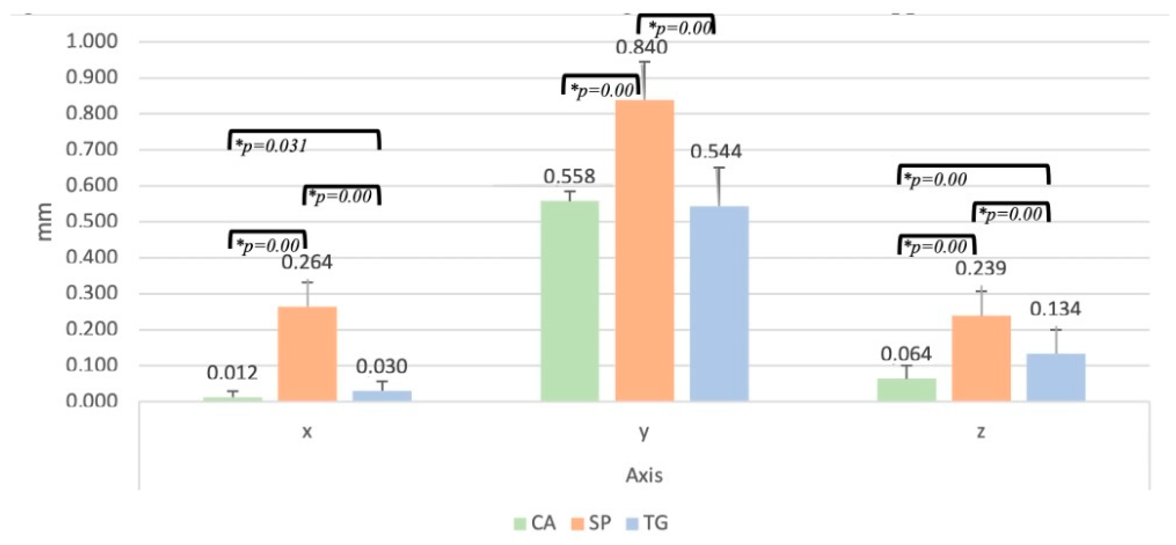
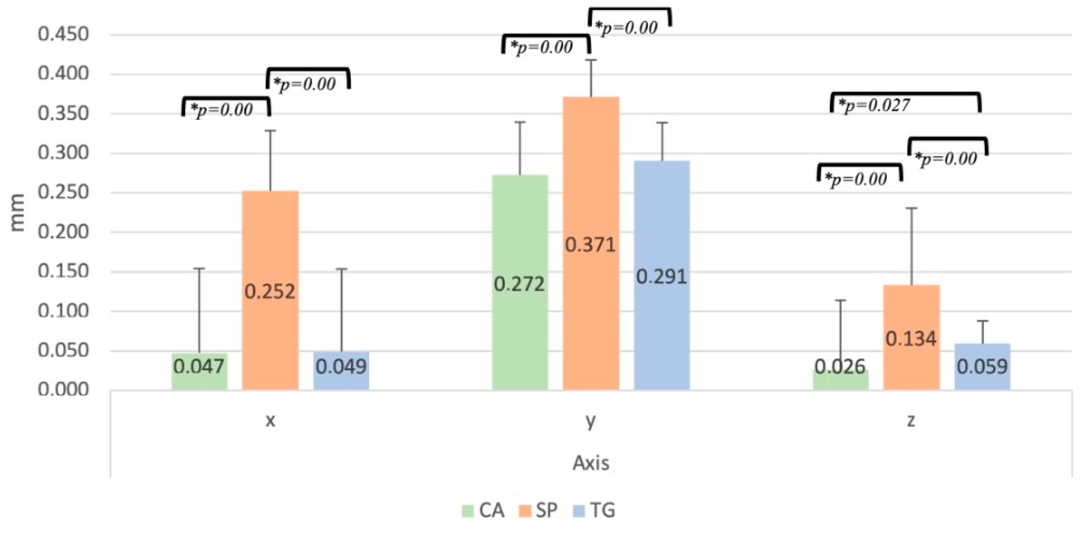
For statistical analysis, the IBM SPSS Software (SPSS Inc., Chicago, IL, USA) version 29.0.0 was used. The normality of data distribution was assessed using the Shapiro–Wilk test and the homogeneity of variances was evaluated by Levene’s test. Statistical analysis of data was performed by one-way ANOVA and Bonferroni post hoc tests. The significance level was set at 0.05.

3. Results

In Figure 2, there is a captured image that illustrates the 3D coordinates of each tracker placed on aligners, on the upper and lower arches.
The mean displacement values of the upper and lower arches for each of the tested aligners are presented in Table 2. The mean values were obtained considering the values of the coordinates of each axis from the reference stage and final loading stage, for each tooth and each arch.
In Figure 3, it can be observed that the highest mean values for each axis were recorded by the samples in group SP. For axis X, the highest mean value was 0.264 ± 0.068 mm; for axis Y, it was 0.840 ± 0.106 mm; and for axis Z, it was 0.239 ± 0.068 mm.
When analyzing the differences between the study groups for axis X, we recorded statistically significant differences between groups CA vs. SP (p = 0.00); TG vs. SP (p = 0.00) and CA vs. TG (p = 0.031). For axis Y, significant differences were observed between groups CA vs. SP (p = 0.00); TG vs. SP (p = 0.00). For axis Z, statistical significance was recorded between groups CA vs. SP (p = 0.00); CA vs. TG (p = 0.00) and TG vs. SP (p = 0.00).
In Figure 4, it can be observed that the highest mean values for each axis was recorded by the samples in group SP. For axis X, the highest mean value was 0.252 ± 0.077 mm; for axis Y, it was 0.371 ± 0.047 mm; and for axis Z, it was 0.134 ± 0.097 mm.
The statistical analysis of the mean values of the rigid displacement for the lower arch showed significant differences within axis X between groups CA vs. SP (p = 0.00) and SP vs. TG (p = 0.00). For axis Y, differences were recorded between groups CA vs. SP (p = 0.00) and SP vs. TG (p = 0.00). Within the mean values recorded for axis Z, statistically significant differences were observed for CA vs. SP (p = 0.00); TG vs. SP (p = 0.00) and CA vs. TG (p = 0.027).
Table 3, Table 4 and Table 5 represent the mean values of the elastic deformation for each of the three tested materials, determined as the difference between the position of the gingival and the incisal tracker on the same tooth. Table 3, Table 4 and Table 5 show the mean values recorded by each material on each axis, for each of the two arches, at each marked point. Comparative statistical analysis of the obtained values for the elastic deformation showed that, for the maxillary arch, significant differences were observed between the values recorded for the X-axis by the CA vs. SP group (p = 0.00) and the CA vs. TG group with a p = 0.00 value. There were no significant differences between the SP and TG groups (p > 0.05). For the Z-axis, the CA group showed significantly higher values compared to the SP group.
For the mandibular arch, the SP and TG groups showed significantly higher Z-axis values compared to the CA group.

4. Discussion

The deformation behavior of clear aligner systems is a critical aspect of orthodontic treatment, impacting the efficacy and comfort of aligners. The present study aimed to investigate the deformation behavior of three different aligner systems—CA® Pro+ Clear Aligner (Scheu Dental, Iserlohn, Germany), Taglus Premium (Taglus Company, Mumbai, India), and Spark Trugen (Ormco Corp., Orange, CA, USA)—under compression, using the digital image correlation (DIC) technique. The null hypothesis posited that no significant differences in deformation behavior would be recorded among these systems.
A study conducted by Casavola et al. investigated the mechanical behavior of PET-G-based aligners using DIC under compression testing [14]. The study found that the DIC technique efficiently captured the deformation phases of the material, providing detailed information on the response of the aligners to mechanical loads. This study supported the use of DIC in evaluating the mechanical behavior of aligners thus motivating our approach. Another research explored the use of DIC to measure the displacement and deformation of aligners during orthodontic treatment [15]. The study confirmed that the DIC technique has demonstrated its effectiveness in capturing the mechanical behavior of aligners, highlighting the distribution of displacement and deformation. A study conducted by Kibitkin also used the two-dimensional DIC technique to characterize the deformation behavior of aligners materials [16]. This study highlighted the ability of DIC to clearly delineate the phases of compressive behavior. The findings of this study are in full agreement with our results on the significant elastic deformation observed in the Spark and Taglus systems.
Images obtained with a high-speed camera have the advantage of a precise measurement of the elastic volume changes [11]. The thickness of the aligner material impacts the force that it generates. The different thickness of the studied aligners was taken into account. ASTM D882-18 and the ISO standard 527 recommend rectangular shapes for tensile testing in thermoplastic materials with a thickness of less than 1 mm [11,17], which also applies to Duran, with a thickness of 0.75 mm. The thickness of clear aligners varies in different teeth, such as the incisors, molars, and in the edentulous areas. 3D printing aligner manufacturing decreases the variation in thickness, leading to more predictable clear aligner treatment outcomes [4,18].
In PET-G materials, such as Taglus Premium, the residual static force and strain recovery rate remain relatively constant even after repeated cyclic loads [4,19], but there is a loss in the ability to exert constant force over a week of use. By applying a cyclic compression of up to 13,000 load cycles from 0 to 50 N, the estimated load to which an aligner is subjected for one week, wear, tear, high depressions, and cracks leading to a loss of force were recorded by digital image correlation and optical microscope analysis in 0.75 mm thick PET-G aligners, at higher levels than in the 0.88 mm thick sample [14,20].
Thermoformed aligners made of the thermo-plastic material Duran showed excessive irreversible deformation during plastic deformation with load application. The displacements were between 1.5 and 2.5 mm for the Duran thermoformed aligners, and the maximum load resistance was found to be almost 200 N [13]. Duran was shown to have a low stress value of 0.5 MPa and a low percentage of normalized stress of 4.6% on a three-point bending test after 14 days of constant deflection. A great decay was also found, with the initial values of 20 MPa being followed by values ranging between 12 MPa and 4 MPa in the 24 h stress relaxation tests [3]. In the Duran materials undergoing ISO527-1 tensile testing, thermoforming caused an increase in yield stress and elastic modulus, a measurement of stiffness, whereas the storage in artificial saliva with its fluid absorption caused a decrease in these parameters due to the plasticizing effect of water [19].
In a study comparing the mechanical properties of four clear aligner materials (Taglus, Essix, Zendura, and Zendura FLX), Taglus displayed a higher elastic modulus and ultimate strength than Essix, which is also a PET-G polymer, just like Taglus. Taglus was the stiffest of the four materials, being even stiffer (8%) than Essix [21]. An in vitro study using an orthodontic simulator and measuring the buccolingual force and moments of a 0.75 mm thick thermoformed Taglus aligner for three maxillary teeth (central incisor, canine, and second premolar) showed a significantly higher mean buccal force and mean moment with a tendency to tip a tooth crown buccally in canine teeth [22]. In comparison, the elastic strain values of the Taglus system were significantly higher than those of the CA Pro+ system. Previous research has also indicated that the materials used in the Taglus aligners’ composition have notable elastic properties [23]. Another study that followed the characterization by DIC confirmed that materials with higher elastic deformation respond better to compression, consistent with our results obtained for the Taglus system [17].
The PONTOS ARAMIS system is a powerful tool that significantly enhances our understanding of aligner deformation behavior. By providing precise, real-time data, it enables the development of better materials, optimized aligner designs, and personalized treatment plans. The integration of PONTOS ARAMIS with advanced computational methods like FEA further amplifies its impact, paving the way for continuous innovation in orthodontic treatment [14,24].
As research and technology continue to evolve, the insights gained from PONTOS ARAMIS analyses will undoubtedly lead to even more effective, durable, and comfortable aligners. This progress will ensure that clear aligners remain at the forefront of orthodontic treatment, offering patients a superior alternative to traditional methods [14,24].
The largest displacement on the Y axis is caused by the function of the articulator and the shape of the aligners. A first indication of the rigidity of the aligners can be seen as a difference between the three types of aligners, thus Spark has the largest displacement, followed by Taglus and Scheu.
The use of the DIC technique in this study provides a solid framework for analyzing the deformation behavior of aligner systems [17,25]. The ability of the technique to capture highly detailed strain and displacement fields provides significant insight into the mechanical properties of the alignment materials. However, it is essential to consider that different investigations may use different methodologies which may influence the results [14].
In our study, the highest values of rigid displacement in both the maxillary and mandibular arches for each of the three axes was recorded by the SP group, in which the specimens were fabricated using the Spark Trugen system. Within each studied axis, the Spark Trugen system showed significantly higher values compared to the other two tested aligner systems. Within axis Z, both maxillary and mandibular, the Taglus Premium system showed significantly higher values compared to the Scheu CA® Pro+ Clear Aligner system.
In terms of elastic deformation, in the maxillary arch, the Scheu system showed lower values in the X-coordinate compared to the other two systems tested. In the mandibular arch, both the Taglus and Spark systems showed higher values at the Z-coordinate compared to the Scheu system. The results of these experiments reproduce the actual operating conditions of the aligners that have a direct clinical significance in the biomedical field. The current study found that the Spark system exhibited the most considerable rigid displacement. This observation is consistent with previous findings that reported significant deformation of PET-G-based aligners under mechanical stress. For instance, a study performed by Casavola revealed a full-field mechanical deformation behavior of PET-G-based aligners including the Spark system [17]. The study demonstrated that PET-G aligners undergo significant deformation when subjected to mechanical loads, which supports our findings. The CA Pro+ Clear Aligner system demonstrated lower values of elastic deformation compared to the Spark and Taglus systems. This finding is supported by studies that have shown that certain alignment materials are designed to provide more stability and less deformation under stress [26,27]. A study that highlighted the image correlation to measure shape and deformation emphasized that different materials used in the composition of aligners react different to mechanical loads, which is consistent with our findings for the CA Pro+ system [26].
According to the literature, the polymer composition and the manufacturing process are responsible for the deformation and relaxation behavior of materials used for aligners [18,22]. For example, a previous study showed that polymers with a higher modulus of elasticity exhibit a lower elastic deformation, which confirms the findings of this study in which the aligner system made of copolyester and thermoplastic elastomer showed the lowest elastic deformation values [9,24]. In addition, the increased deformation resistance in the mandibular area of all the three systems is consistent with previous research highlighting the variability of deformation behavior depending on the dental arch thus suggesting the need for customized approaches in orthodontic treatments [27].
Based on the study findings, the clear aligner system based on copolyester and thermoplastic elastomer emerged as the most suitable and user-friendly option, particularly due to its superior resistance to elastic deformation and rigid displacement in compression tests. This is in line with other consistent findings in the literature, in which aligners with higher stability and lower deformation are often preferred for consistent orthodontic results [24,28]. Given its demonstrated stability, the clear aligner system based on copolyester and thermoplastic elastomer should be further recommended to patients seeking reliable and durable aligner solutions that guarantee effective and predictable treatment outcomes.
Given these results, it is admitted that the null hypothesis of the study has been rejected. However, future studies are needed to replicate, as closely as possible, the oral environment through the presence of saliva, masticatory movements, or changes in temperature or pH [29,30]. The research activity should also focus on standardizing the test protocols for the DIC analysis of alignment materials to ensure comparability of results across different studies. In addition, exploring the long-term effects of repeated mechanical loading on the deformation behavior of aligners may provide additional insights into their durability and performance in clinical contexts [31,32].
In conclusion, the findings of the present study, which indicate significant differences in the deformation behavior among the three alignment systems, are consistent with those reported by other researchers using the DIC technique as an evaluation method. The substantial rigid displacement of the Spark system as well as the higher elastic deformation values of the Spark and Taglus systems align with the findings of previous studies. These results emphasize the importance of considering the material properties and mechanical behavior in the design and selection of transparent alignment systems for orthodontic treatment.

5. Conclusions

  • In conclusion, the Spark Trugen clear aligner system demonstrated a lower stability to rigid displacement and elastic deformation under compression testing compared to the Scheu CA® Pro+ Clear Aligner and Taglus Premium systems.
  • All three tested clear aligner systems showed an increased resistance to elastic displacement and rigid deformation in the mandibular arch.
  • The Scheu CA® Pro+ Clear Aligner system showed the lowest elastic deformation values after compression testing.

Author Contributions

Conceptualization, N.D.O., D.F.C. and N.S.; methodology, T.P.; software, A.C. and D.F.C.; validation, D.F.C., N.D.O. and I.N.Z.; formal analysis, S.N.R.; investigation, N.D.O. and D.F.C.; resources, N.D.O. and I.N.Z.; data curation, D.F.C.; writing—original draft preparation, N.D.O. and D.F.C.; writing—review and editing, I.N.Z. and C.S.; visualization, S.N.R.; supervision, I.N.Z. and N.S.; project administration, N.D.O.; funding acquisition, N.D.O. All authors have read and agreed to the published version of the manuscript.

Funding

This research received no external funding.

Institutional Review Board Statement

The study was conducted in accordance with the Declaration of Helsinki and approved by the Ethics Committee of “Grigore T. Popa” University of Medicine and Pharmacy of Iași (approval no. 56, approval date 12 March 2021).

Informed Consent Statement

Informed consent was obtained from all subjects involved in the study.

Data Availability Statement

The original contributions presented in the study are included in the article, further inquiries can be directed to the corresponding authors.

Conflicts of Interest

The authors declare no conflicts of interest.

References

  1. Bichu, Y.M.; Alwafi, A.; Liu, X.; Andrews, J.; Ludwig, B.; Bichu, A.Y.; Zou, B. Advances in orthodontic clear aligner materials. Bioact. Mater. 2023, 22, 384–403. [Google Scholar] [CrossRef] [PubMed]
  2. Hennessy, J.; Al-Awadhi, E.A. Clear aligners generations and orthodontic tooth movement. J. Orthod. 2016, 43, 68–76. [Google Scholar] [CrossRef] [PubMed]
  3. Albertini, P.; Mazzanti, V.; Mollica, F.; Pellitteri, F.; Palone, M.; Lombardo, L. Stress Relaxation Properties of Five Orthodontic Aligner Materials: A 14-Day In-Vitro Study. Bioengineering 2022, 9, 349. [Google Scholar] [CrossRef] [PubMed]
  4. Lee, S.Y.; Kim, H.; Kim, H.J.; Chung, C.J.; Choi, Y.J.; Kim, S.J.; Cha, J.Y. Thermo-mechanical properties of 3D printed photocurable shape memory resin for clear aligners. Sci. Rep. 2022, 12, 6246. [Google Scholar] [CrossRef]
  5. Voudouris, J.C.; Voudouris, J.D.; Nicolay, O.; Glaser, B.; Nicozisis, J.; Theodoridis, G.; Carrillo, R.; Moshiri, M.; Masoud, M. Clear aligners, dentofacial orthopedics, physics and supercorrection prescription biomechanics. A meeting of the minds. Semin. Orthod. 2022, 27, 202–258. [Google Scholar] [CrossRef]
  6. Bucci, R.; Rongo, R.; Levatè, C.; Michelotti, A.; Barone, S.; Razionale, A.V.; D’Antò, V. Thickness of orthodontic clear aligners after thermoforming and after 10 days of intraoral exposure: A prospective clinical study. Prog. Orthod. 2019, 20, 36. [Google Scholar] [CrossRef]
  7. Zinelis, S.; Panayi, N.; Polychronis, G.; Papageorgiou, S.N.; Eliades, T. Comparative analysis of mechanical properties of orthodontic aligners produced by different contemporary 3D printers. Orthod. Craniofac Res. 2022, 25, 336–341. [Google Scholar] [CrossRef]
  8. Jindal, P.; Juneja, M.; Siena, F.L.; Bajaj, D.; Breedon, P. Mechanical and geometric properties of thermoformed and 3D printed clear dental aligners. Am. J. Orthod. Dentofacial Orthop. 2019, 156, 694–701. [Google Scholar] [CrossRef]
  9. Shirey, N.; Mendonca, G.; Groth, C.; Kim-Berman, H. Comparison of mechanical properties of 3-dimensional printed and thermoformed orthodontic aligners. Am. J. Orthod. Dentofacial Orthop. 2023, 163, 720–728. [Google Scholar] [CrossRef]
  10. Mao, B.; Tian, Y.; Li, J.; Zhou, Y. Expansion rebound deformation of clear aligners and its biomechanical influence: A three-dimensional morphologic analysis and finite element analysis study. Angle Orthod. 2023, 93, 572–579. [Google Scholar] [CrossRef]
  11. Zhang, Y.; Jin, X.; Savoldi, F.; Han, J.; Su, R.K.L.; Fok, A.; Chen, J.; Tsoi, J.K. Validation of a double-semicircular notched configuration for mechanical testing of orthodontic thermoplastic aligner materials. J. Mech. Behav. Biomed. Mater. 2024, 155, 106543. [Google Scholar] [CrossRef] [PubMed]
  12. Can, E.; Panayi, N.; Polychronis, G.; Papageorgiou, S.N.; Zinelis, S.; Eliades, G.; Eliades, T. In-house 3D-printed aligners: Effect of in vivo ageing on mechanical properties. Eur. J. Orthod. 2022, 44, 51–55. [Google Scholar] [CrossRef] [PubMed]
  13. Jindal, P.; Worcester, F.; Siena, F.L.; Forbes, C.; Juneja, M.; Breedon, P. Mechanical behaviour of 3D printed vs thermoformed clear dental aligner materials under non-linear compressive loading using FEM. J. Mech. Behav. Biomed. Mater. 2020, 112, 104045. [Google Scholar] [CrossRef] [PubMed]
  14. Casavola, C.; Pappalettera, G.; Pappalettere, C.; Patronelli, M.; Renna, G.; Laurenziello, M.; Ciavarella, D. A full-field DIC analysis of the mechanical-deformation behavior of polyethylene terephthalate glycol (PET-G) aligners. J. Mech. Behav. Biomed. Mater. 2022, 134, 105391. [Google Scholar] [CrossRef]
  15. Schreier, H.; Orteu, J.J.; Sutton, M.A.; Michael, A.M.A.; Orteu, J.J.; Schreier, H.W. Single Camera Models and Calibration Procedures in Computer Vision. In Image Correlation for Shape, Motion and Deformation Measurements; Michael, A., Sutton, M.A., Orteu, J.J., Schreier, H.W., Eds.; Springer: New York, NY, USA, 2009; pp. 1–37. [Google Scholar]
  16. Kibitkin, V.; Savchenko, N.; Grigoriev, M.; Solodushkin, A.; Burlachenko, A.; Buyakov, A.; Zykova, A.; Rubtsov, V.; Tarasov, S. Digital Image Correlation Characterization of Deformation Behavior and Cracking of Porous Segmented Alumina under Uniaxial Compression. Ceramics 2023, 6, 102–131. [Google Scholar] [CrossRef]
  17. Casavola, C.; Pappalettera, G.; Pappalettere, C.; Patronelli, M.; Renna, G.; Ciavarella, D.; Laurenziello, M. DIC analysis of mechanical response of tooth aligners under simulated swallowing acts. IOP Conf. Ser. Mater. Sci. Eng. 2023, 1275, 012023. [Google Scholar] [CrossRef]
  18. Lümkemann, N.; Klimenta, M.; Hoffmann, M.; Meinen, J.; Stawarczyk, B. Dimensional Stability and Reproducibility of Varying FFF Models for Aligners in Comparison to Plaster Models. Materials 2023, 16, 4835. [Google Scholar] [CrossRef]
  19. Tamburrino, F.; D’Antò, V.; Bucci, R.; Alessandri-Bonetti, G.; Barone, S.; Razionale, A.V. Mechanical properties of thermoplastic polymers for aligner manufacturing: In vitro study. Dent. J. 2020, 8, 47. [Google Scholar] [CrossRef]
  20. Hertan, E.; McCray, J.; Bankhead, B.; Kim, K.B. Force profile assessment of direct-printed aligners versus thermoformed aligners and the effects of non-engaged surface patterns. Prog. Orthod. 2022, 23, 49. [Google Scholar] [CrossRef]
  21. Keller, K.J.; Keller, K.J.; Giannini, P.J.; Gregory, M.S.; Oakley, G. Stress Relaxation in Orthodontic Aligner Plastics; An In Vitro Stress Relaxation in Orthodontic Aligner Plastics; An In Vitro Comparison Study Comparison Study Stress Relaxation In Orthodontic Aligner Plastics; An In Vitro Comparison Study [Internet]. 2020. Available online: https://digitalcommons.unmc.edu/etd (accessed on 5 June 2024).
  22. Kaur, H.; Truong, J.; Heo, G.; Mah, J.K.; Major, P.W.; Romanyk, D.L. An in vitro evaluation of orthodontic aligner biomechanics around the maxillary arch. Am. J. Orthod. Dentofacial Orthop. 2021, 160, 401–409. [Google Scholar] [CrossRef]
  23. Sawamura, M.; Nakano, H.; Shiogama, M.; Takano, N.; Maki, K. Using digital image correlation to measure displacement and strain during involving distal movement of anterior teeth with clear aligner. Dent. Mater. J. 2023, 42, 493–500. [Google Scholar] [CrossRef] [PubMed]
  24. Grünheid, T.; Bitner, T.F. Wear and fatigue resistance: An in-vitro comparison of three polyethylene terephthalate glycol and thermoplastic polyurethane materials for vacuum-formed retainers. Int. Orthod. 2023, 21, 100748. [Google Scholar] [CrossRef] [PubMed]
  25. Milovanović, A.; Sedmak, A.; Golubović, Z.; Mihajlović, K.Z.; Žurkić, A.; Trajković, I.; Milošević, M. The effect of time on mechanical properties of biocompatible photopolymer resins used for fabrication of clear dental aligners. J. Mech. Behav. Biomed. Mater. 2021, 119, 104494. [Google Scholar] [CrossRef] [PubMed]
  26. Lyu, X.; Cao, X.; Yan, J.; Zeng, R.; Tan, J. Biomechanical effects of clear aligners with different thicknesses and gingival-margin morphology for appliance design optimization. Am. J. Orthod. Dentofacial Orthop. 2023, 164, 239–252. [Google Scholar] [CrossRef]
  27. Nowak, C.M.; Othman, A.; Ströbele, D.A.; von See, C. Comparative mechanical testing for different orthodontic aligner materials over time—In vitro study. J. Clin. Exp. Dent. 2022, 14, e457–e463. [Google Scholar] [CrossRef]
  28. Dalaie, K.; Fatemi, S.M.; Ghaffari, S. Dynamic mechanical and thermal properties of clear aligners after thermoforming and aging. Prog. Orthod. 2021, 22, 15. [Google Scholar] [CrossRef]
  29. Golkhani, B.; Weber, A.; Keilig, L.; Reimann, S.; Bourauel, C. Variation of the modulus of elasticity of aligner foil sheet materials due to thermoforming. J. Orofac. Orthop. 2022, 83, 233–243. [Google Scholar] [CrossRef]
  30. Morris, R.S.; Hoye, L.N.; Elnagar, M.H.; Atsawasuwan, P.; Galang-Boquiren, M.T.; Caplin, J.; Viana, G.C.; Obrez, A.; Kusnoto, B. Accuracy of Dental Monitoring 3D digital dental models using photograph and video mode. Am. J. Orthod. Dentofac. Orthop. 2019, 156, 420–428. [Google Scholar] [CrossRef]
  31. Ryu, J.H.; Kwon, J.S.; Jiang, H.B.; Cha, J.Y.; Kim, K.M. Effects of thermoforming on the physical and mechanical properties of thermoplastic materials for transparent orthodontic aligners. Korean J. Orthod. 2018, 48, 316–325. [Google Scholar] [CrossRef]
  32. Doğramacı, E.J.; Chubb, D.W.R.; Rossi-Fedele, G. Orthodontic thermoformed retainers: A two-arm laboratory study into post-fabrication outcomes. Aust. Dent. J. 2018, 63, 347–355. [Google Scholar] [CrossRef]
Figure 1. Overview of the experimental setup used for the assessment of the deformation behavior of clear aligners.
Applsci 14 07496 g001
Figure 2. Captured image of the 3D coordinates of each tracker placed on aligners.
Applsci 14 07496 g002
Figure 3. Mean values and standard deviations of rigid displacement for upper arch. * Statistically significant differences between groups are indicated by black line.
Applsci 14 07496 g003
Figure 4. Mean values and standard deviations of rigid displacement for lower arch. * Statistically significant differences between groups are indicated by the black line.
Applsci 14 07496 g004
Table 1. Distribution of the samples and the material compositions.
GroupAligner SystemManufacturer Composition and Material Thickness
CA (n = 15)CA® Pro+ Clear AlignerScheu Dental, Iserlohn, GermanyThree layers (0.75 mm):
1. Copolyester layer (0.25 mm)
2. Thermoplastic elastomer (TPE) (0.25 mm)
3. Copolyester layer (0.25 mm)
TG (n = 15)Taglus PremiumTaglus Company, Mumbai, IndiaPolyethylene terephtalate glycol (PET-G)
(0.75 mm)
SP (n = 15)Spark TrugenOrmco Corp., Orange, CA, USATruGEN Technology (0.75 mm)
Table 2. DIC hardware parameters.
Camera SensorCMOS
Camera Resolution4096 × 3000 pixels
Frame Rate25 fps @ full resolution
43 fps @ 2496 × 2096 pixels (5M mode)
IlluminationLight Projector
Tracking Spots
Measuring Area [mm]Frame 150: 35|70|120|180
Frame 300: 110|170|260|400|550
Frame 600: 750|1500
Frame 1200: 1500|3000
Frame 1600: 5000
Control DeviceARAMIS Controller
Sensor Size [mm]Frame 150: approx. 260 × 330 × 300
Frame 300: approx. 420 × 330 × 300
Frame 600: approx. 730 × 230 × 130
Frame 1200: approx. 1300 × 230 × 130
Frame 1600: approx. 1700 × 230 × 130
Strain Measuring Range0.005% up to >2000%
Strain Measuring Resolutionup to 0.005%
Table 3. Elastic deformation determined as the difference between the position of the gingival and the incisal tracker on the same tooth for SCHEU CA® Pro+ material.
AlignerNo. Point3 *2 *12 *3 *
Scheu
Upper
Axis[mm][mm][mm][mm][mm]
X0.0230.011 0.0160.023
Y0.0020.005 0.0060.001
Z0.0090.054 0.0330.001
Scheu
Lower
321123
X0.0070.0070.0020.0030.0060.013
Y0.0030.0030.0030.0020.0010.002
Z0.0170.0170.010.0170.0140.003
* indicates the maxillary points.
Table 4. Elastic deformation determined as the difference between the position of the gingival and the incisal tracker on the same tooth for Spark Trugen Material.
AlignerNo. Point3 *2 *12 *3 *
Spark
Upper
Axis[mm][mm][mm][mm][mm]
X0.0070.008-0.0330.034
Y0.0070.003-0.010.02
Z0.0050.05-0.0240.027
Spark
Lower
321123
X0.010.0020.00150.0140.0140.002
Y0.00100.0060.0080.0060.007
Z0.0110.0090.00150.0210.0270.03
* indicates the maxillary points.
Table 5. Elastic deformation determined as the difference between the position of the gingival and the incisal tracker on the same tooth for Taglus Premium material.
AlignerNo. Point3 *2 *12 *3 *
Taglus
Upper
Axis[mm][mm][mm][mm][mm]
X0.0020.008 0.0190.044
Y0.0050.016 0.010.009
Z0.0240.053 0.0260.026
Taglus
Lower
321123
X0.0020.0080.0020.0040.0090.002
Y0.0010.010.0050.0060.0030.007
Z0.010.0480.0170.020.0180.03
* indicates the maxillary points.
Disclaimer/Publisher’s Note: The statements, opinions and data contained in all publications are solely those of the individual author(s) and contributor(s) and not of MDPI and/or the editor(s). MDPI and/or the editor(s) disclaim responsibility for any injury to people or property resulting from any ideas, methods, instructions or products referred to in the content.

