Article

Influence of Fractal Disc Filter Flow Channel Parameters on Filtration Performance

1
College of Water Resources and Civil Engineering, China Agricultural University, Beijing 100083, China
2
Zhejiang Toumen Port Investment & Development Co., Ltd., Taizhou 317015, China
*
Author to whom correspondence should be addressed.
Appl. Sci. 2024, 14(17), 7505; https://doi.org/10.3390/app14177505 (registering DOI)
Submission received: 6 July 2024 / Revised: 2 August 2024 / Accepted: 22 August 2024 / Published: 25 August 2024

Abstract

:
The research and development of a new disc filter is a key link in intelligent irrigation systems, the core of efficient and water-saving irrigation development, and also an important joint effort to ensure a clean water source in micro-irrigation systems. In this paper, the independent research and development of the fractal flow passage disc filter was taken as the research object, and the disc filter numerical simulation cell (FLUENT) and artificial intelligence technology (Back Propagation Neural Network) were combined to optimize the filter flow channel parameters, including the tilt angle, the length and height of the bottom of the internal section triangle, the taper, the position and number of buffer slots, etc. A new type of disc filter with lower head loss, larger flow capacity, higher filtration efficiency, and longer running time is proposed. It has certain reference value and promotion significance for the future development and design of high-performance disc filters and their wide use.

1. Introduction

In recent years, the vigorous development of information technology and big data [1] has continuously promoted the transformation of traditional water conservancy to smart water conservancy. At the same time, the irrigation rate of cultivated land in China is as high as 51%, 2.68 times the world average of 19% [2]. Under the background of the rapid development of agricultural production and irrigation science and technology [3], smart irrigation is increasingly welcomed by farmers. With the support of massive agricultural information and data, the use of artificial intelligence and the Internet of Things (AI+IOT) can solve the inefficiency of traditional agriculture [4,5], improve the efficiency of fine operations, and realize fine irrigation, intelligent fertilization, and pest and disease identification. This will not only promote the development of accurate, efficient, and green agriculture but also improve the level of agricultural information and intelligence and provide technical support for the expansion of the agricultural Internet of Things.
The disc filter is a key part of the intelligent irrigation system, and its characteristics of accurate filtration, thorough and efficient backwashing, automatic operation, and continuous water discharge provide an important guarantee for pollution control, farmland irrigation water quality, and irrigation efficiency. In order to improve the filtration effect and work efficiency of disc filters in intelligent irrigation systems, a large number of scholars have improved the macrostructure of disc filters. Xiao XM et al. [6] combined a sand filter and a disc filter to design a laminated sand filter. The new product has a large filtration capacity and a small head loss. Xiao XP et al. [7] proposed a new type of stacked mesh filter for agricultural drainage and irrigation that is simple in structure and far exceeds the performance index of similar domestic filters. Wang J et al. [8] developed a hydraulic piston disc filter with a transparent shell, which has a more uniform head loss and growth range; Zhang JW [9] designed a set of water flow and sediment separation systems based on centrifugal and disc filters, and the filtration effect has been significantly improved. Hou JX et al. [10] conducted a DPM model-based numerical simulation study on rectangular and triangular groove laminators, respectively, and found that the triangular groove disc filter had small head loss, uniform flow rate distribution, and high filtration efficiency. Li N et al. [11] found that the laminated thickness and section bottom angle of the disc filter affect its flow capacity, while the tilt angle has almost no effect on the filter head loss. Wu WY et al. [12] combined the disc filter with the sand and gravel filter, and found that the combination increased the removal rate by about 20% after filtering the reclaimed water. Cui R et al. [13] fuse two kinds of flow passage with different mesh numbers into one stack, and the results show that the composite flow passage stack has less head loss. Khan TA et al. [14] tested the filtering performance of a disc filter with clay and sand particles and found that the filtration efficiency of sand is higher than that of clay with a certain flow range in the filter.
The fractal theory was first proposed by Mandelbrot [15] to describe binding objects with extremely irregular shapes. At the same time, the fracture theory is suitable for small-scale scientific research and is widely used in microflow passage [16,17]. The flow state inside the disc filter is turbulent, and the internal flow [18] channel is complicated and difficult to observe directly. Therefore, the fractal theory can be used to optimize the structure of the disc filter’s internal micro-channel. Li YK et al. [19] used the fractal curve to construct a more complex flow passage boundary in the design of the emitter’s labyrinth flow passage, which reduced the flow index of the emitter. By using the simplified Koch Fractal curve, Zhang C et al. [20] designed the trapezoidal Fractal flow passage at 1/2 place that is most easy to sediment deposition. Ma ZX et al. [21] used the Minkowski Fractal Curve to design the flow passage inside the lamination and found that the long flow passage has better filtering performance. Chi YB et al. [22] simulated the filter operation process with the macroscopic and simplified model and found that the patterns of head loss among all of the disc filters were consistent.
The introduction of fractal theory provides a new idea for the optimal design of fractal disc filters. After the fracture curve is added along the stack, the optimal stack can have a longer flow channel length at an appropriate angle, and the fine deflection angle is also conducive to sediment settlement in the flow. At the same time, the buffer slot is added to the fractal curve to provide more sediment settlement and effectively reduce the water head loss during the filtration process of the disc filter. Therefore, the design of a new disc filter based on the Fractal Theory can improve the running time of the system and reduce head loss. This paper will focus on how to further improve the filtration performance of the fractal flow passage disc filter developed by our research group and reduce energy consumption.

2. Materials and Methods

The design of fractal disc filter mainly consists of two parts [23,24]: (1) With the analysis of flow channel characteristics and operating principles in the disc filter, the Minkowski curve was introduced. The fractal curve was applied along the central axis of the internal flow channels of the discs, with the fractal height being 0.30 mm. This design is shown in Figure 1a. (2) The buffer slot was designed for the middle area of the internal flow channels of the discs. The depth of the buffer slot and the flow channel in the entrance direction of the discs should be consistent, and the bottom edge should be straight. The width of the buffer slot is 0.40 mm. This design is shown in Figure 1b. The main difference between traditional disc filter and fractal disc filter is embodied in the fractal flow channel and the design of the buffer slot. This comparison is shown in Figure 1c.
The filtration accuracy of a disc filter is controlled by the diameter of the flow passage internal circle, so the premise of flow passage optimization is that the internal circle diameter of the flow passage internal section (filtration accuracy) is unchanged. The optimization of the laminar flow passage structure is affected by many parameters, but these parameters are not completely independent of each other. Therefore, this paper intends to select parameters such as the tilt angle of the flow passage, the length and height of the bottom of the internal section triangle, the taper, the position, and the number of buffer slots for optimization.

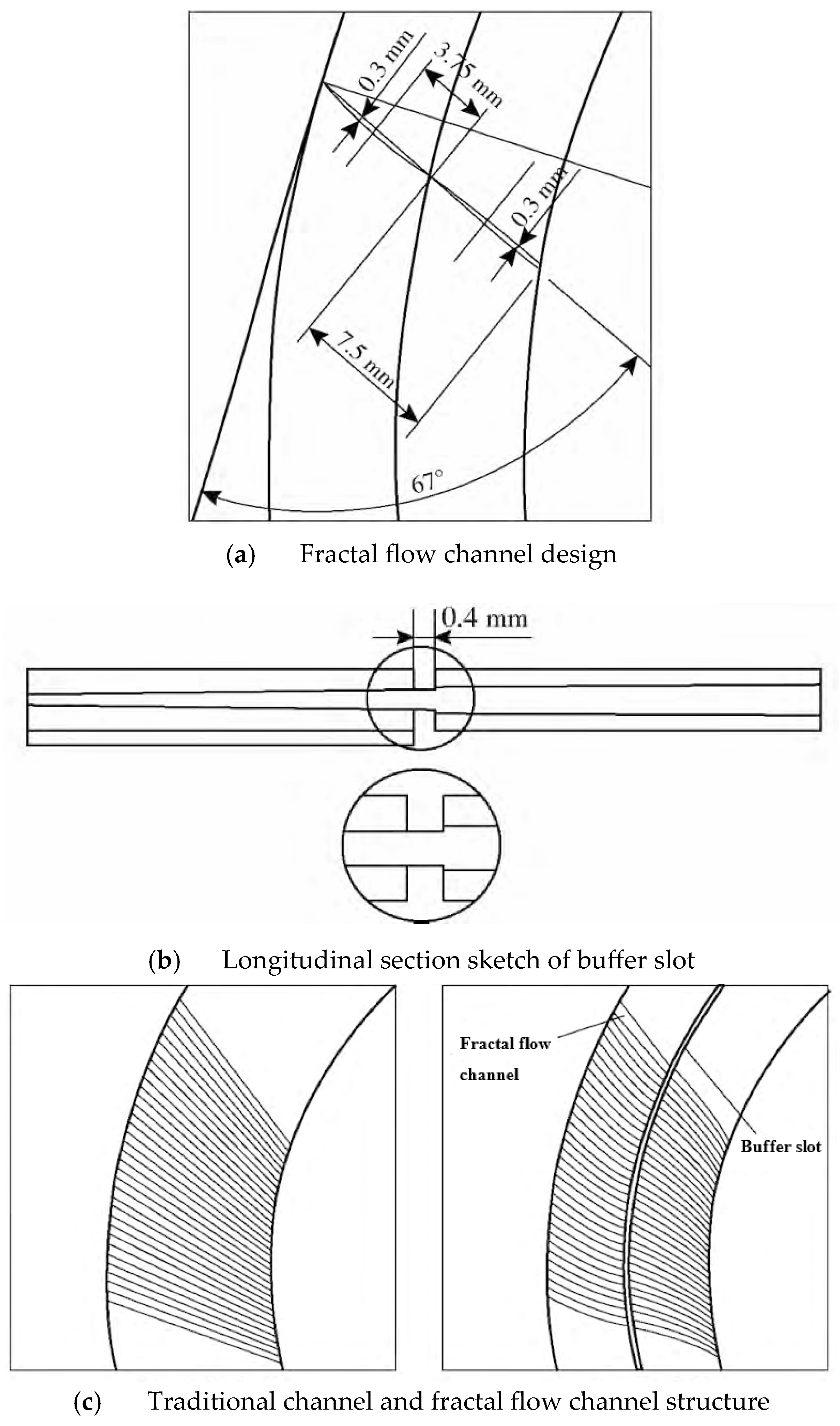
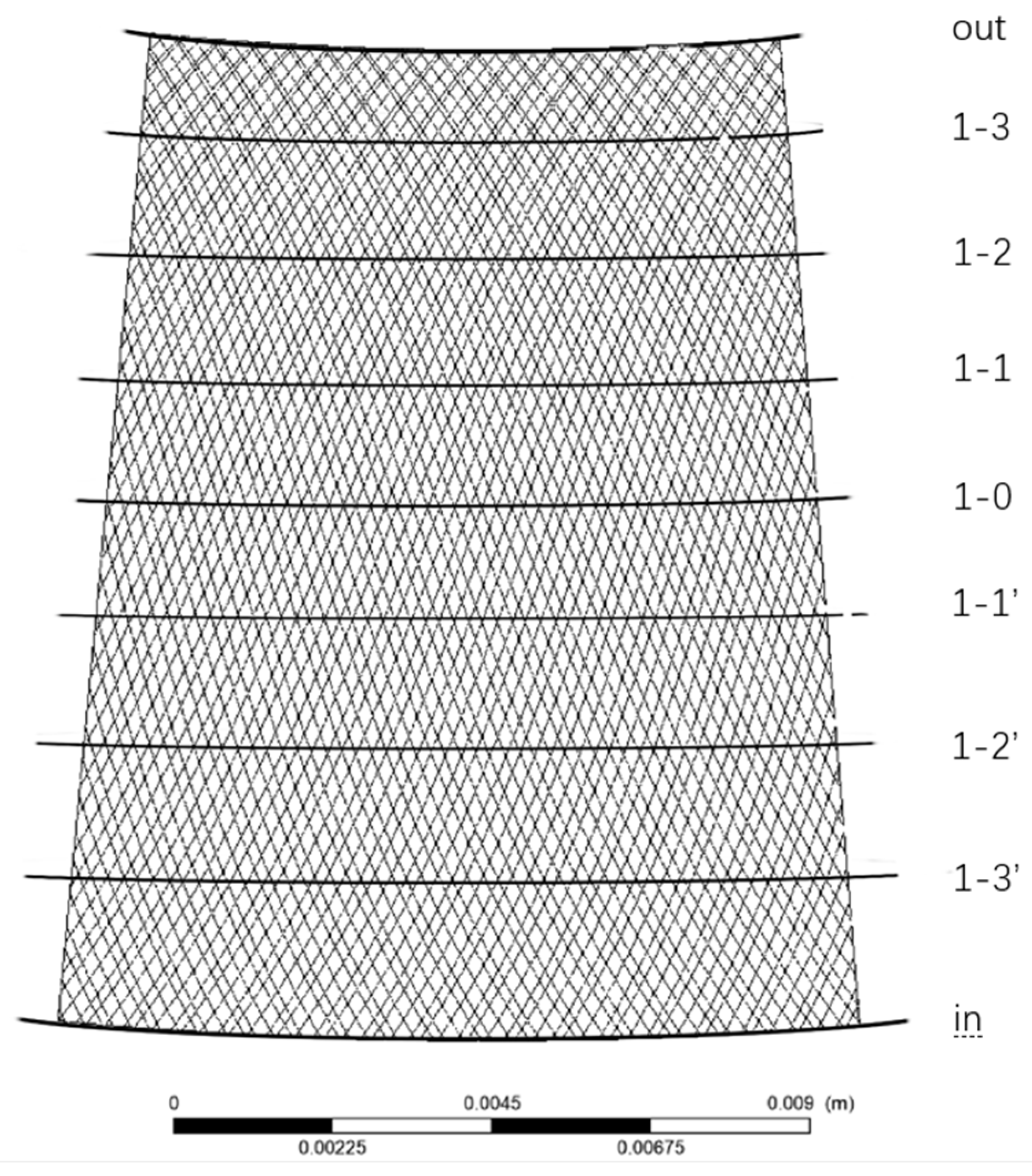
2.1. The Number and Position of Buffer Slot
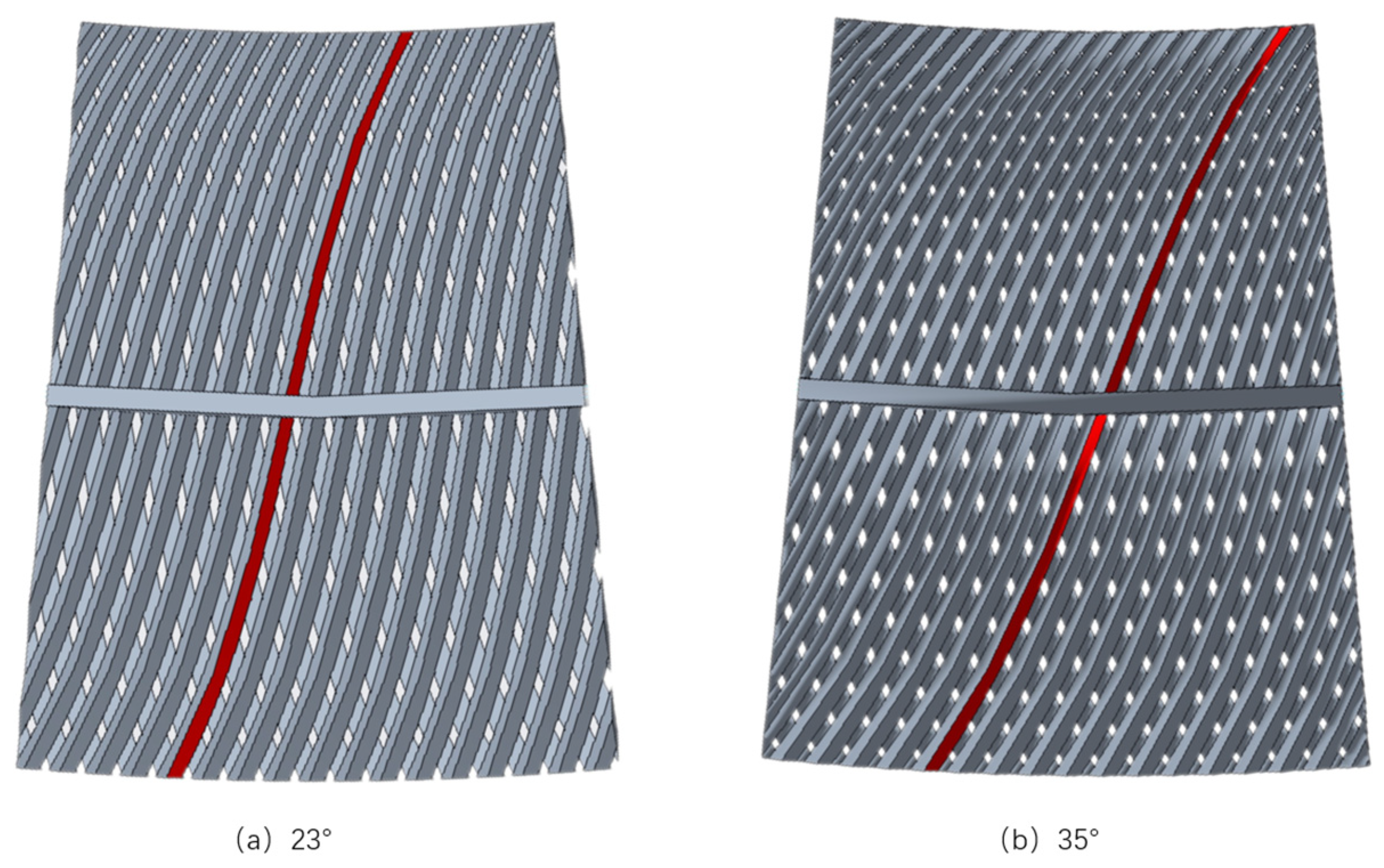
In the filter performance test, it was found that the flow passage in the first half of the traditional DC channel disc filter makes it very easy to block sand. Due to the narrow characteristics of the flow passage itself, the blocked flow passage is difficult to filter, resulting in the shortening of the entire filter operation cycle. At the same time, because the sand cannot enter the flow passage inside, it results in a large area of laminated waste with low filtration efficiency. Therefore, the fractal disc filter is added to the buffer slot design to buffer the water flow in the process of laminated filtration to achieve the role of reducing local water head loss and assisting sediment settlement.
In order to test the effectiveness and placement of the buffer slot, it was set at the following six locations: The numerical simulation was carried out for the laminations with no buffer slot and a different buffer slot, respectively. The position distribution of the buffer slot is shown in Figure 2.

2.2. The Tilt Angle

The tilt angle of different brands of filters is different, and the difference in tilt angle will lead to a difference in the number of intersections of upper and lower flow passage water bodies. In this paper, the lamination with tilt angles of 25° and 35° is taken as an example, and the difference in the number of intersections is shown by the red-marked point in Figure 3.
The figure shows that there are more intersections of upper and lower flow passage water bodies with larger flow passage inclination angles. When the inclination angle of the flow passage is 23°, 1 flow passage and 15 flow passages have intersection points. When the inclination angle of the flow passage increases to 35°, the average flow passage intersects with 23 flow passages. If the inclination angle of the flow passage is too small, the upper and lower flow passages cannot form an intersection point, while if the inclination angle of the flow passage is too large, the internal sections of adjacent flow passages will adhere to each other and cannot form an independent triangle. Based on the above two points, the tilt angle is controlled to change between 10° and 35°, and the step size is 5°.

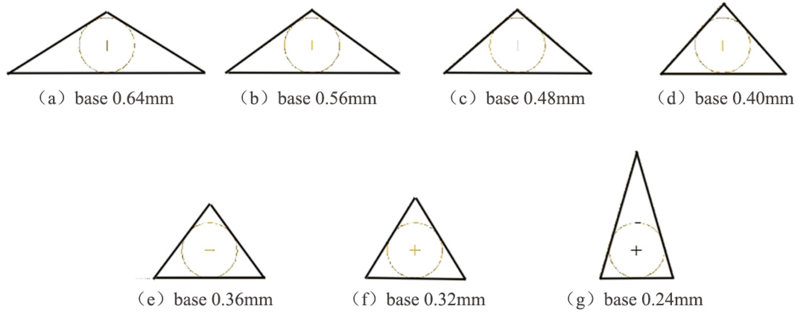
2.3. The Cross Section Shape

In order to increase the amount of sediment and intercept sediment of different particle sizes, the entrance section of the laminated flow passage is larger than the exit section. The inner circle shape of the exit section determines the filtration accuracy of the lamination. Each section shape of the laminated flow passage is an isosceles triangle of different shapes, and the size of the base and height of the triangle determine the shape of the isosceles triangle. Therefore, the flow passage of triangles with different internal sections is simulated without changing the filtering accuracy or taper.
The bottom length of the inner section is 0.24 mm minimum and 0.64 mm maximum, and the gradient is 0.08 mm. Before optimization, the bottom side length of the fractal disc filter was 0.36 mm. Observe Table 1 and Figure 4 for the specific parameters and dimensions of the triangle in the inner section.
The maximum cross-sectional area of a single flow passage does not correspond to the cross-sectional area of the whole filter element. With the decrease in bottom side length, the triangular area of a single inner section decreases first and then increases. The minimum area is 0.050 mm2, and the corresponding bottom side length is 0.32 mm. The maximum area is 0.076 mm2, and the corresponding bottom side length is 0.64 mm. The minimum cross-section area of the whole filter element is 19,421.28 mm2, and the corresponding bottom surface length is 0.24 mm. The maximum value is 20,558.50 mm2, and the corresponding bottom side length is 0.40 mm.
On the premise that the diameter of the tangent circle remains unchanged, the height of the triangle increases continuously with the decrease in base length. The triangular base of a single flow passage section decreases at the cost of increasing the section height. The larger the section height is, the larger the lamellar thickness is. And the height of the filter element is certain; the greater the thickness of the lamination, the smaller the number of laminations. The formula is as follows:
S = 2 × S 1 × n × m
where S1 is the section area of a single flow passage; the unit is mm2; n is the number of flow passages on the stack; m is the number of stacked pieces installed on the filter element.

2.4. The Taper

The ratio of the difference in diameter of the bottom circle above and below the table to the height of the table is defined as the taper. The flow passage of disc filter is similar to that of a triangular platform with small internal section and large external section, so the calculation formula for its taper is defined as follows:
T = d 1 d 2 l
where T is the taper; d1 and d2 are respectively the diameters of the tangential circles of the upper and lower sections of the triangular platform, in mm; l is the length of the laminated flow passage (unit: mm).
To make the laminated flow passage complete, the taper of the flow passage is changed on the premise that the triangular area shape of the inner section is unchanged and the number of the laminated flow passage is unchanged. The different taper flow passage is reflected in the difference in the external cross-section area. When the area of the inner circle of the inner and outer sections is the same, the taper is 0. Because the number of laminated flow passages is constant, the length of the bottom edge of the outer section of the laminated section is limited. Through calculation, when the bottom edge of the outer section is larger than 0.60, the laminated flow passage is no longer complete, and the corresponding taper is 0.0080. Therefore, the taper range is 0~0.0080, and the step size is 0.0020. The taper of the stack flow passage before optimization is 0.0039, which is close to 0.0040, so the taper of the stack before optimization is replaced by 0.0040. The relationship between laminate taper and flow passage external section area is shown in Table 2.

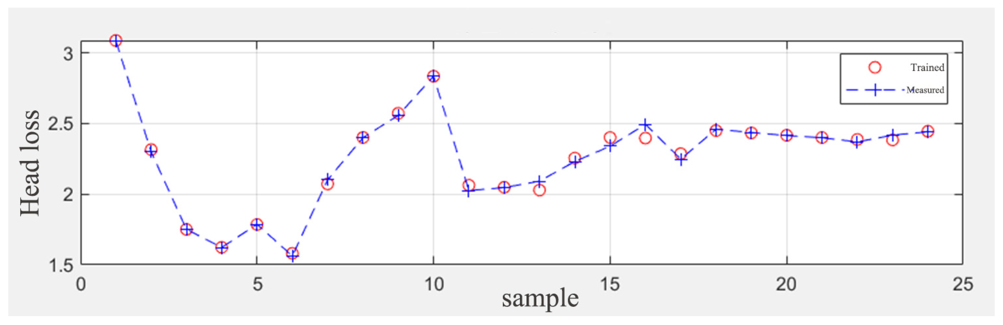
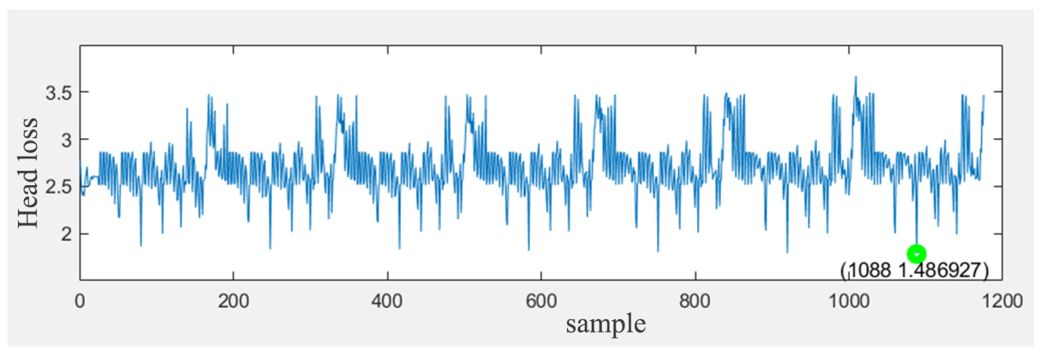
2.5. The BP Neural Network Model

To verify whether the optimal values of single flow passage parameters are consistent with those of multiple flow passage parameters. There are 7 kinds of placement positions for the buffer groove, 6 kinds of values for the flow passage inclination angle, 7 kinds of values for the flow passage internal section, and 4 kinds of values for the flow passage taper. The values of the above parameters are randomly arranged and combined, and a total of 1176 kinds of combination forms are obtained. Then the BP Neural Network model is used to learn 1176 combinations and predict the optimal values of various flow passage parameters.
The BP Neural Network optimization model [25,26] for configuring a variety of flow passage parameters of disc filter is designed. The learning flow chart is shown in Figure 5.
The optimized model consists of three layers: input layer, hidden layer, and output layer, with complete connections between layers and no connections between neurons in the same layer. The data set of buffer groove location, flow passage inclination angle, flow passage internal section shape, and taper is taken as the input layer, and the data set of head loss is taken as the output layer.
The number of nodes in the hidden layer of the neural network [27] is determined by the following formula:
l = i + k + a
where i represents the number of nodes in the input layer. There are four parameters affecting the disc filter, so 4 is taken. k represents the number of output nodes. In this example, the water head loss evaluates the performance of the filter, so 1 is taken; a is a constant [28] between 0 and 10. The number of nodes in the hidden layer is too small to meet the sample learning requirements, and too many samples will appear to exhibit an overfitting phenomenon [29] caused by too long training time. In summary, the number of nodes in the hidden layer in this example is 4, which can satisfy the complex mapping relationship.
Due to the different orders of magnitude of the four input parameters, it is necessary to perform normalization processing before training the data:
X i = X i 0 X m i n X m a x X m i n
where the value range is [0, 1], which indicates the data after normalization (i = 1,2,3,4); Xi, Xi0 are the input data; Xmax, Xmin are the maximum and minimum values in the input data.
The hidden layer of the BP Neural Network uses the Log-Sigmoid function. The Log-Sigmoid function has the advantage of being more accurate and fault-tolerant than linear functions. Its expression is:
l o g s i g n = 1 1 + e n
where n is the independent variable.
To prevent the output value from being restricted to 0~1 or 1~1, the output layer uses the linear function Purelin, whose expression is:
f n = k n
where n is the independent variable and k is the constant.

3. Results and Discussion

3.1. Influence of Single Flow Passage Parameter on Filtration Performance

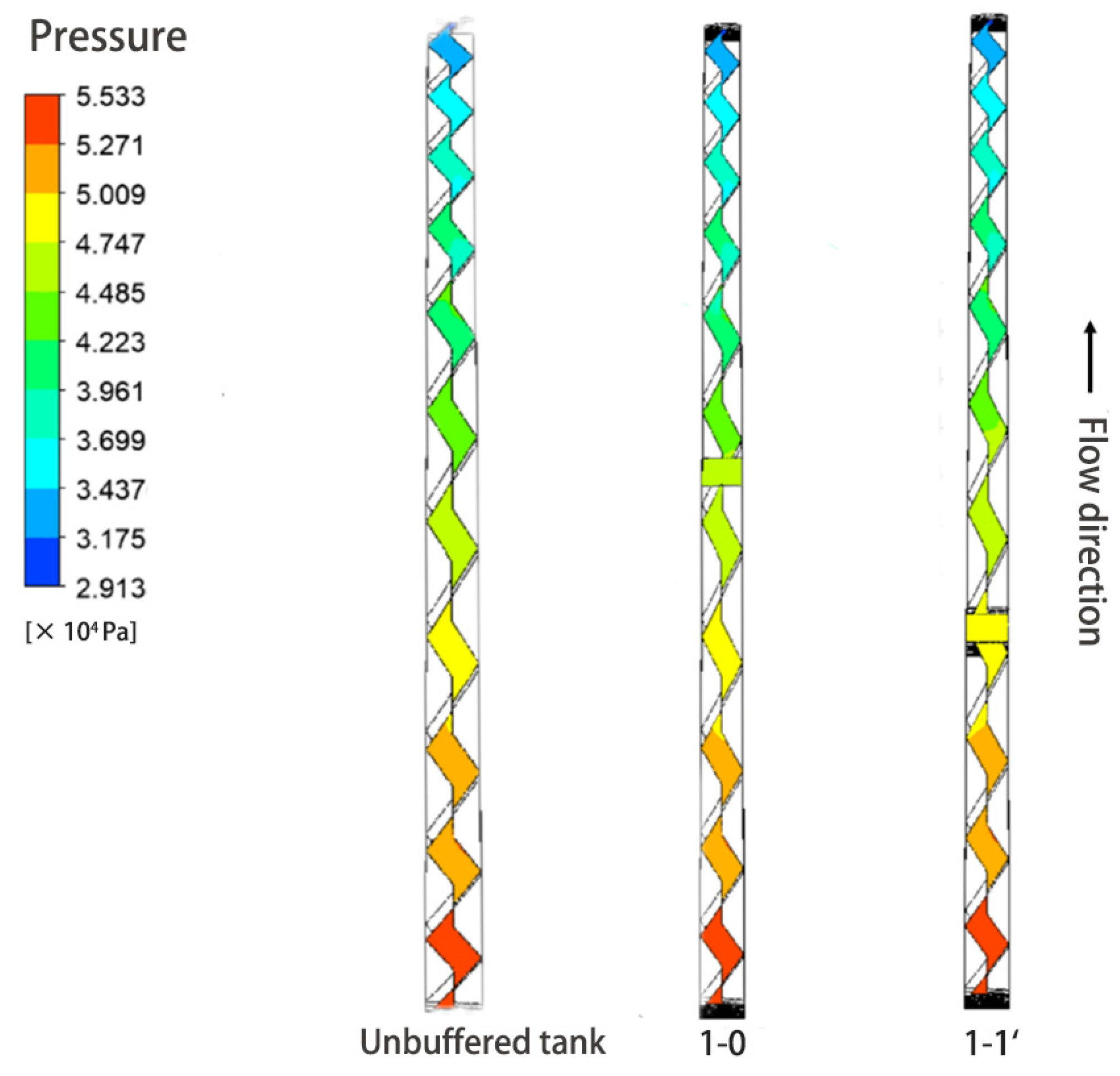
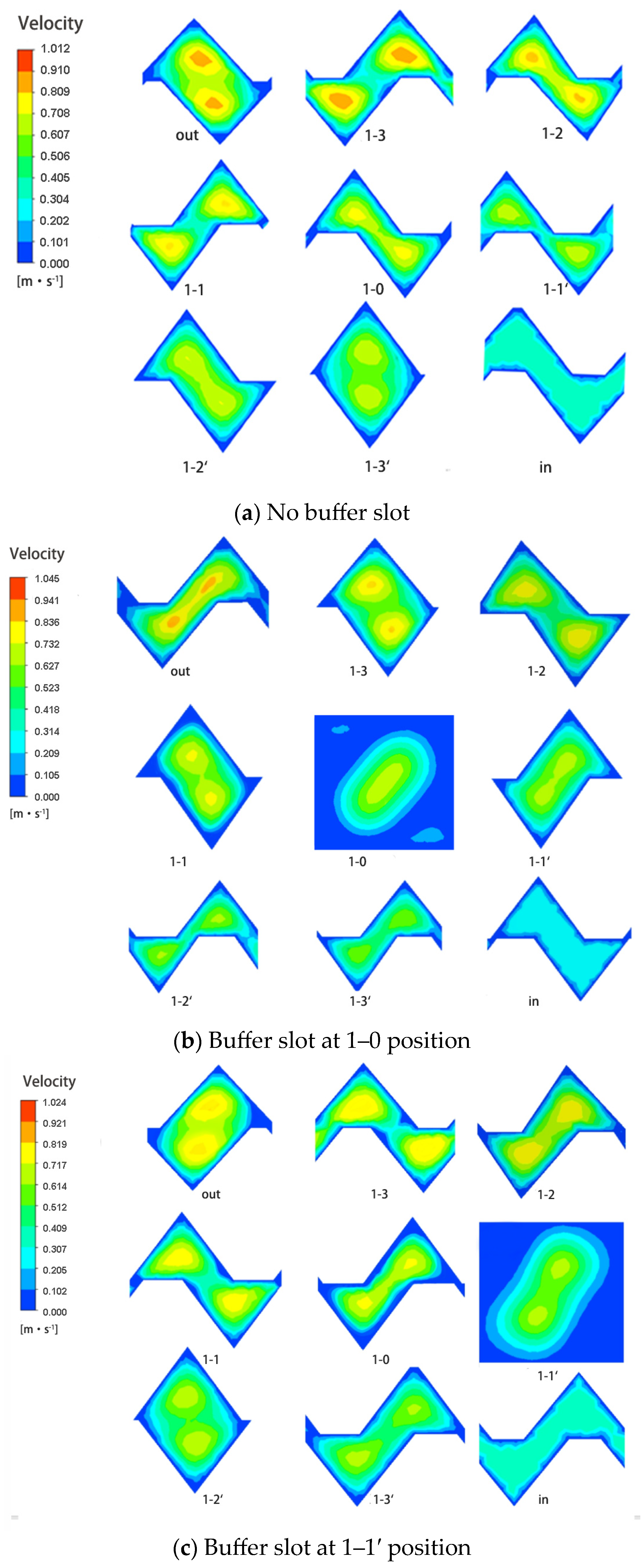
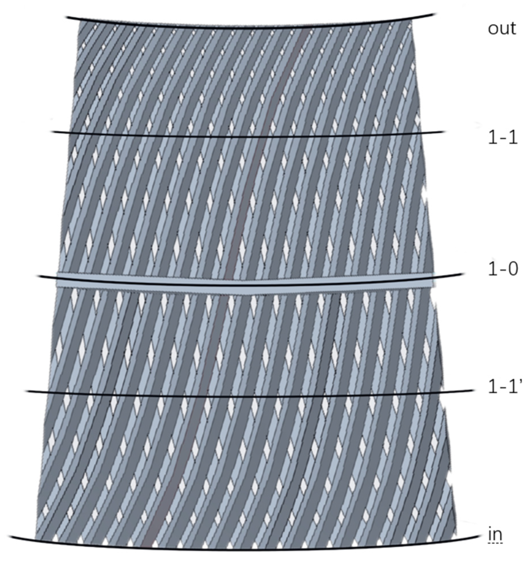
3.1.1. The Number and Position of Buffer Slot

In order to facilitate the observation of the laminated pressure changes, the pressure of the radial section was analyzed, and the flow passage pressure distribution diagram of the radial section is shown in Figure 6. The presence or absence of buffer grooves has a certain influence on the overall pressure distribution of laminate. The pressure distribution of the stack with a buffer groove is more uniform than that of the stack without a buffer groove. The pressure distribution at 1–1′ is more uniform than that at 1–0. In order to further study the change of velocity in the flow passage, the flow passage is cut into different sections along the flow direction (as shown in Figure 2). The fractal flow passage without buffer groove, the flow passage before optimization (the buffer groove is located at 1–0 position), and the simulated optimized buffer groove flow passage (the buffer groove is located at 1–1′ position) are respectively shown. The internal flow velocity changes are shown in Figure 7.
In Figure 6 and Figure 7, The red series means high pressure and fast flow velocity, and the blue series means low pressure and slow flow velocity. According to the color distribution presented in this figure, the velocity of each section of flow passage is high in the center and low at the edge. The flow velocity of each section of the stack with a buffer groove is lower than that of the stack without a buffer groove, and the flow velocity changes relatively slowly. Because the buffer groove increases the flow area of the section, the flow velocity of the section decreases and the low-speed area increases. Water flow enters the inner flow passage after flowing through the buffer slot. The decrease in flow area results in an increase in velocity in the main flow area. However, compared with the flow passage without a buffer slot, the low-speed zone near the flow passage wall is larger, indicating that the design is more conducive to sediment interception. The low flow velocity of the buffer trough reduces its sand-carrying capacity, resulting in large particle-size sediment being deposited in the low-speed area of the buffer trough and small-particle sediment flowing out with the flow. When the buffer slot is located at the 1–1′ section, the velocity area of the 1–2′ section in the low-speed zone and the main flow zone account for 16.4% and 15.9% of the section area, respectively. When the buffer slot is located at 1–0 section, the velocity area of 1–2′ section in the low-speed zone and the main flow zone account for 14.8% and 3.6% of the section area, respectively. The main stream area is large; the laminated flow passage is not easy to plug, while the low-speed area is large, which makes it easy to deposit sediment. Therefore, the optimized lamination effectively avoids the condition that the first half of the filter flow passage is prone to depositing most of the sediment and exiting the working state prematurely, thereby extending the running time of the filter and reducing the number of backwashes.
The above results show that the existence of buffer slots can not only reduce the loss of water head but also facilitate the interception of sediment. As the position of the buffer slot moves from the flow passage inlet to the flow passage outlet, the head loss decreases first and then increases, and the head loss reaches its lowest when the buffer slot is located at 1–1′. The filtration performance of a disc filter is better when the position of the flow passage buffer slot is 1–1′.

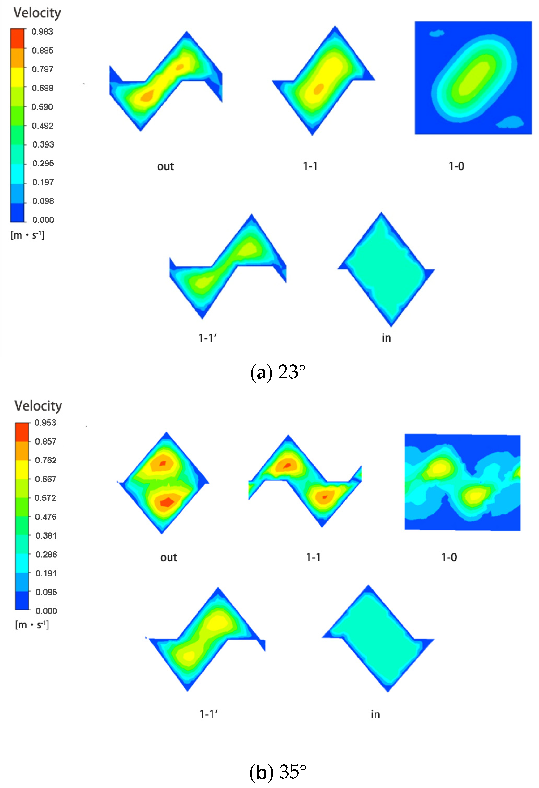
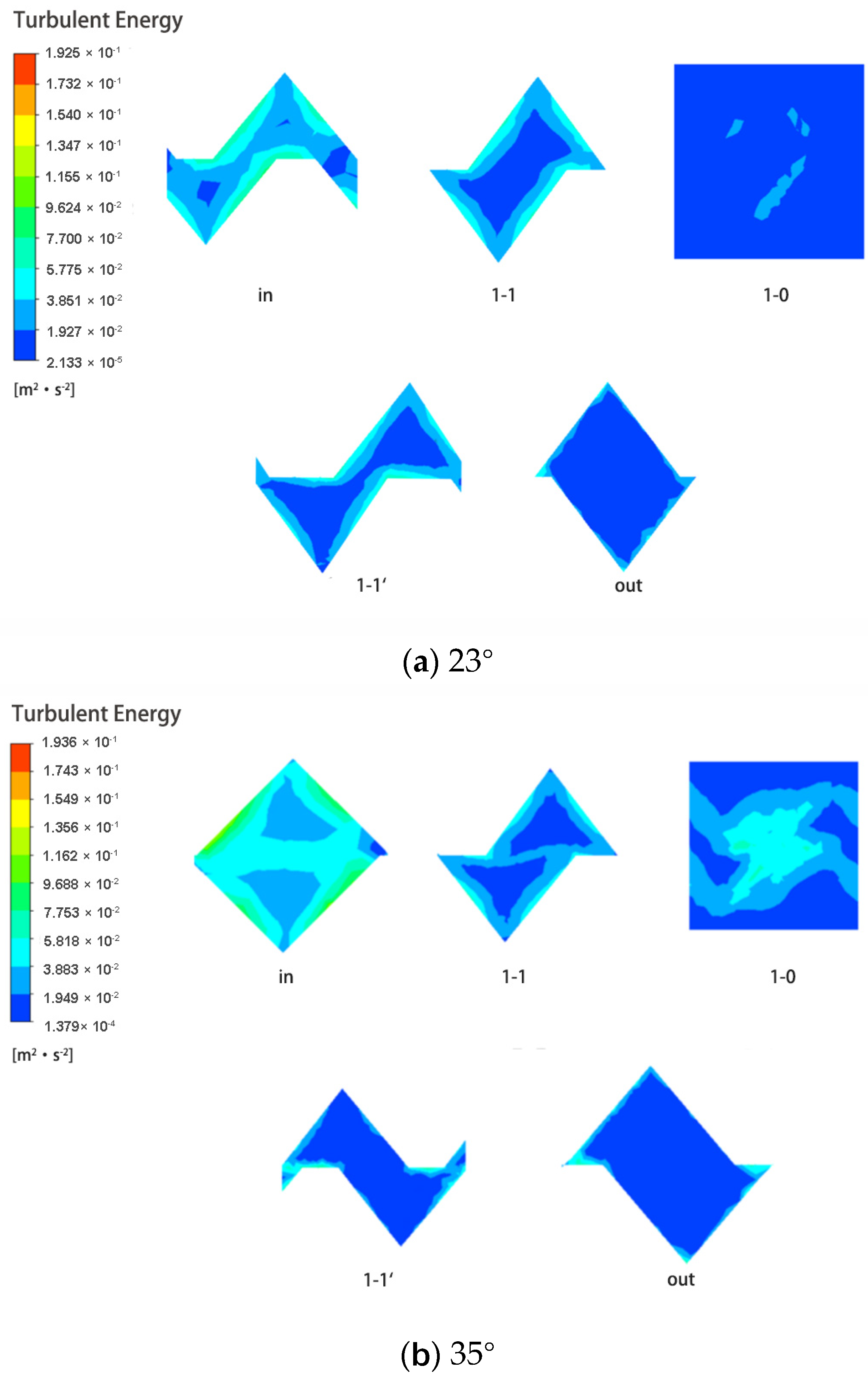
3.1.2. The Tilt Angle

With the increase in flow passage inclination angle, the flow capacity of the laminate is gradually increased. Under the same inlet pressure, the larger the flow capacity of the stack, the better the filtration performance of the disc filter. Therefore, from the perspective of flow capacity, under the condition that the flow passage exit section is complete, the stack with a tilt angle of 35° is better than the stack with a tilt angle of 23°. In order to verify the above conclusions and conveniently observe the changes in velocity and turbulent kinetic energy in the flow passage, five different cross sections were selected for observation. The locations of cross sections are shown in Figure 8, and the velocity and turbulent kinetic energy cloud images of each section are shown in Figure 9 and Figure 10.
According to the presented color distribution in Figure 9 and Figure 10, the velocity nephograms of different flow passage inclination angles show that the maximum velocity of the 35° inclination angle is located at the center of the flow passage exit, and the velocity is about 0.95 m/s. The maximum flow rate of the flow passage at a 23° inclination angle is also located at the center of the flow passage exit, with a maximum of 0.88 m/s. The lowest flow rate for both tilt angles is located at the edge of the flow passage and can be as low as 0 m/s. The high flow rate in the main stream area reduces the risk of clogging the filter in the early stage of operation, so that the filter has a longer running time, while the low flow speed near the wall reduces the sand-carrying capacity of the water here, which can effectively deposit sediment and improve the filtration efficiency of the disc filter. By comparing the velocities of the two inclined angle laminar sections at the 1–0 section (the section where the buffer slot is located), it is found that the velocity in the main flow zone of the 23° flow passage changes obviously, but there is no mixing phenomenon in the main flow zone between different flow passages. The 35° flow passage maintains a high speed in the transition region where the two main flow regions are connected, except for the obvious changes in the main flow region. It shows that the 23° laminated buffer slot only increases the overflow area and promotes sediment deposition, while the 35° laminated buffer slot not only promotes sediment deposition but also exchanges water flow between different flow passages. By comparing the turbulent kinetic energy of the two tilting angle laminators, it is found that the turbulent kinetic energy in the mainstream area is the lowest and increases from the middle to the periphery. The turbulent kinetic energy strength of the 35° stack is greater than that of the 23° stack after passing through the buffer groove. According to the comparison and analysis of the flow velocity cloud map, although the turbulence intensity in the mainstream area is small, the sand particles will not be deposited because of the high flow velocity. Near the wall, the turbulent kinetic energy of the 35° dip angle is not much different from that of the 23° dip angle, so it will not affect the sediment deposition.
The above results show that the lamination with a 35° inclination is superior to the lamination with a 23° inclination before optimization. The filter performance of a disc filter is better when the flow passage angle is 35°.

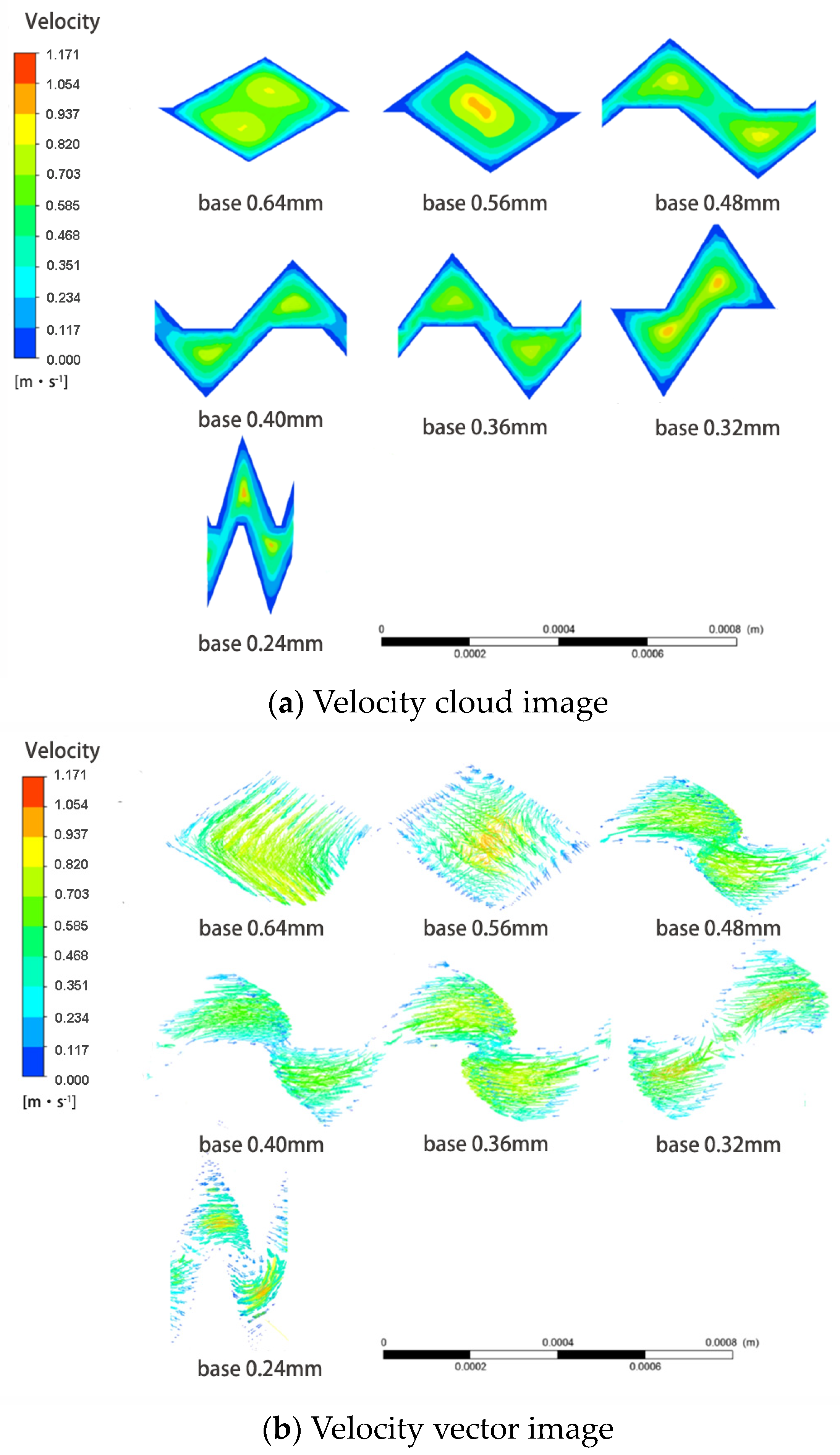
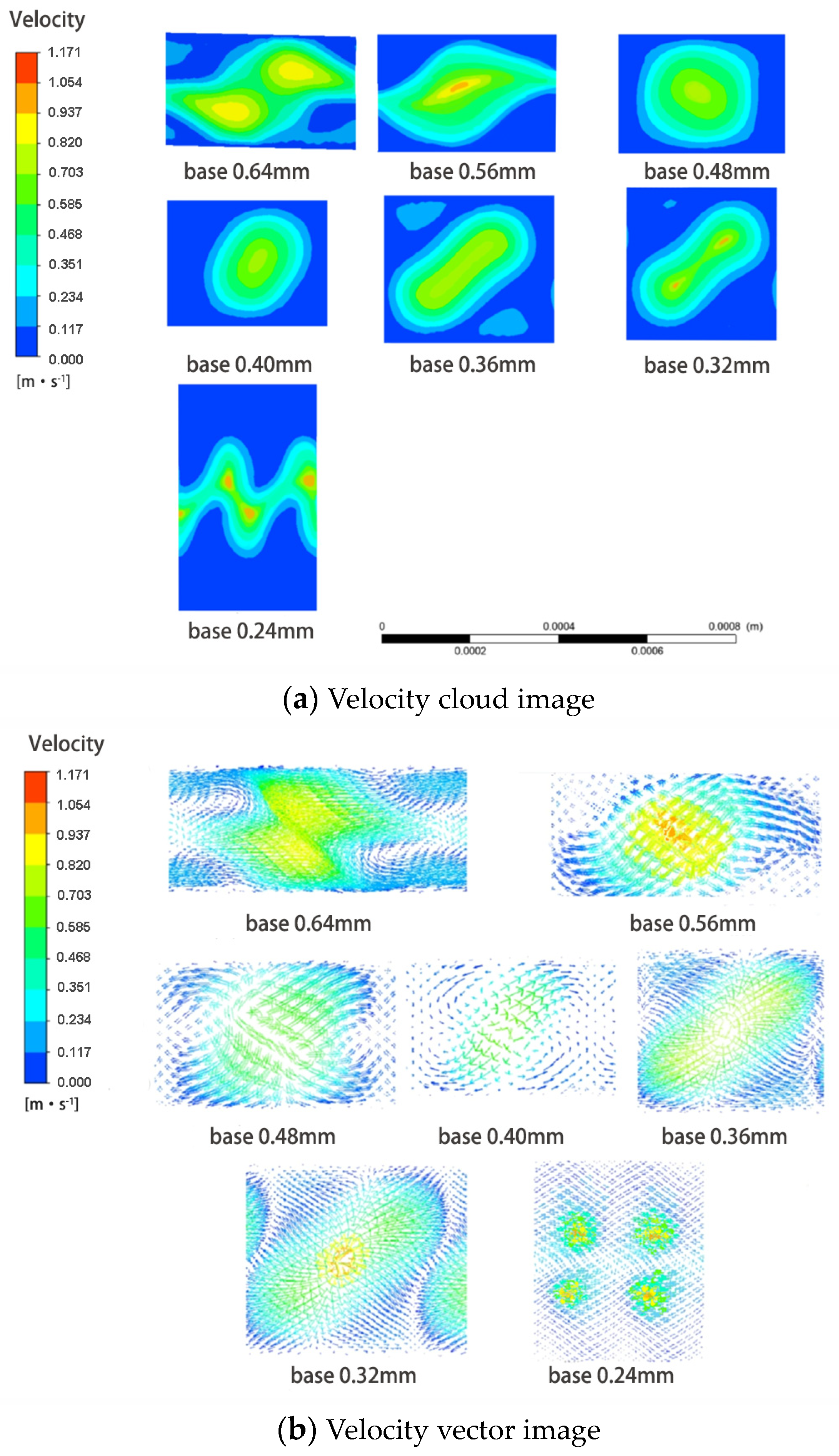
3.1.3. The Cross Section Shape
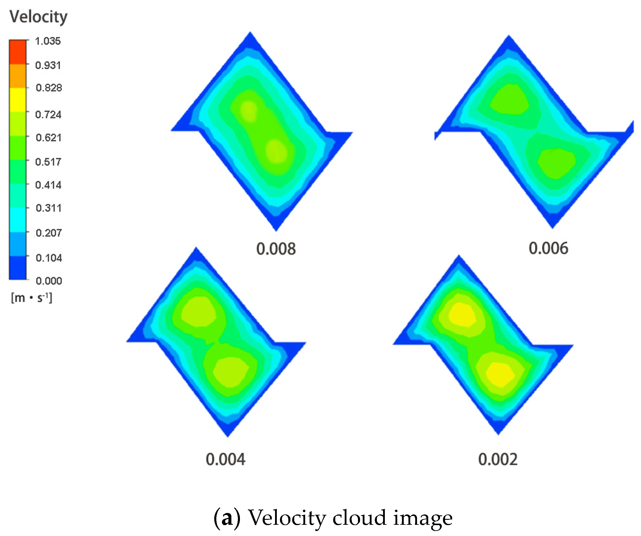
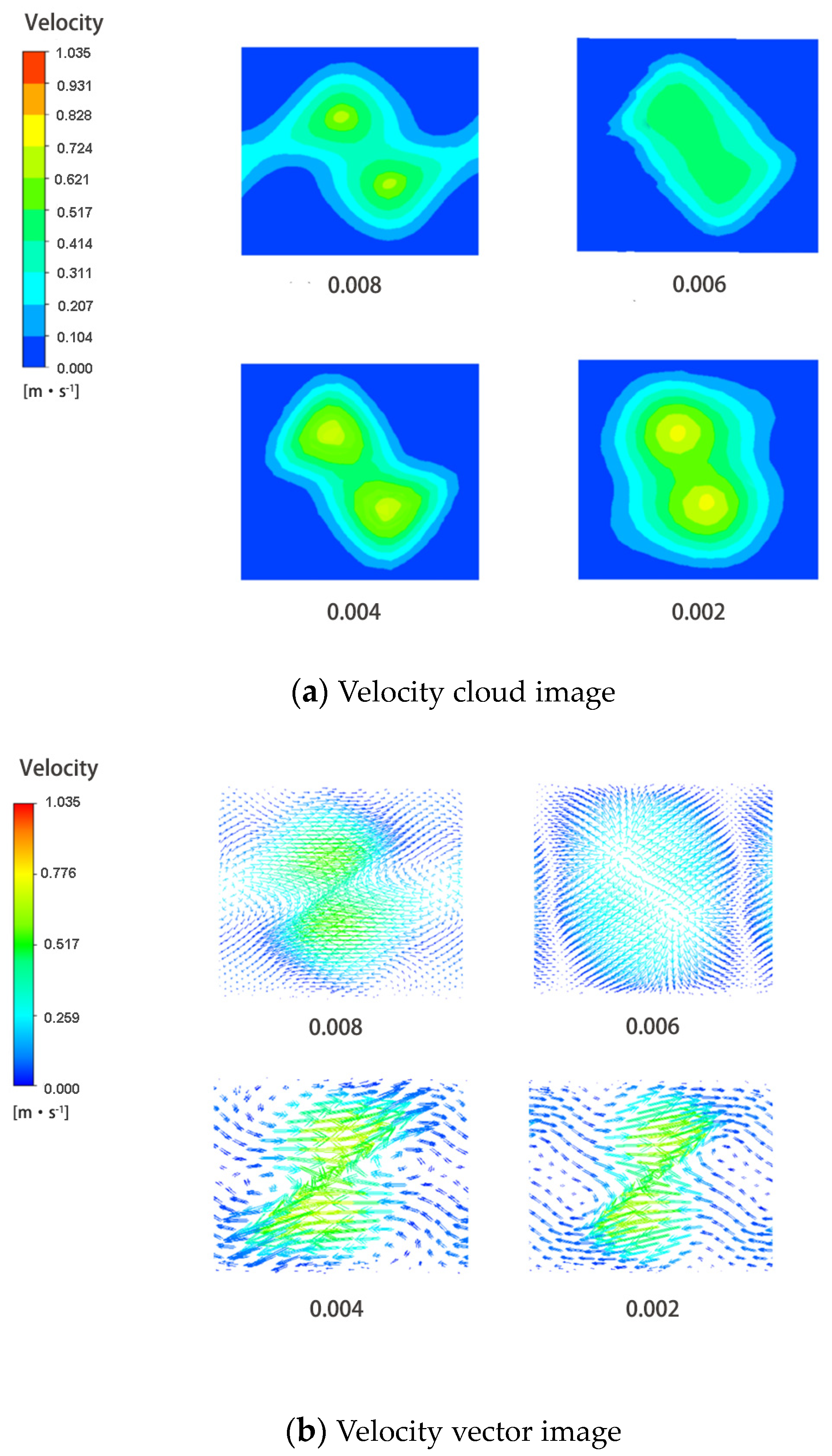
With the increase in length of the bottom edge of the inner section, the head loss presents a trend of slow increase, large increase, and decrease at first. When the bottom length of the section reaches 0.32 mm, the head loss reaches its maximum value of 2.49 m. By comparing the triangular shape of the section corresponding to different bottom lengths, it can be found that the closer the section of flow passage is to the regular triangle, the greater the head loss.
In order to further understand the flow characteristics of the water body in the flow passage, the velocity cloud images and velocity vector cloud images of different sections were observed. The locations of cross sections are shown in Figure 11. The velocity cloud image and velocity vector cloud image of the 1–1′ section with different base sizes are shown in Figure 12. The velocity cloud image and velocity vector cloud image of the 1–0 section with different base sizes are shown in Figure 13. Because the 1–1′ section is the easiest to clog sediment, and the buffer slot also plays a role in exchanging water and depositing sediment, it is important to monitor the buffer slot sections of the 1–1′ section and the 1–0 section.
Based on the presented color distribution in Figure 12, a comparative analysis between Figure 12a,b reveals that the flow rate of the flow passage at sections 1–1′ does not decrease with the increase in the cross-sectional area of a single flow passage but is related to the cross-sectional area of the whole filter element. For flow passages with bottom lengths of 0.56 mm, 0.32 mm, and 0.24 mm, the flow velocity in the main flow zone at the 1–0 section is above 0.93 m/s, which is larger than the other three sections. The water body in the main flow area of Section 1–0 of the flow passage, with a bottom length of 0.56 mm and 0.24 m is changed with the adjacent flow passage. For sections with a bottom length of 0.56 mm and 0.32 mm, the area of the low-speed zone near the wall accounts for 21.6% and 21.8% of the section area, respectively, which are larger than other sections. The 1–1′ section is located in front of the buffer slot, and according to the laminar filtration performance test, the 1–1′ section is the section that is most likely to clog sediment. If the flow rate of the mainstream area here is too small, the large particle-size sediment is relatively easy to deposit, which will hinder the operation of the filter. At the same time, in order to improve the filtration performance of the filter, sediment should be deposited as much as possible. From this point of view, the larger mainstream flow rate and the larger low-speed area near the wall are conducive to the operation of the filter. Therefore, the cross section with the bottom edge of 0.56 mm and 0.32 mm is relatively better. Except for the sections with base edges of 0.64 mm and 0.56 mm, the flow velocity of the remaining sections has a clear trend in parallel to the flow of the section. Since the overall flow direction of the flow passage water body flows from the inlet to the outlet, spiral flow appears in the flow passage water body after the disturbance of the parallel cross-section velocity vector, and the corresponding head loss increases. Therefore, in order to obtain the lamellar with a small head loss, it is necessary to make the velocity vector as parallel as possible to the flow cross section. Therefore, the cross sections with base edges of 0.64 mm and 0.56 mm are relatively better.
Based on the presented color distribution in Figure 13, a comparative analysis between Figure 13a,b reveals that the velocity cloud map of the main flow area at the section of buffer groove with a bottom edge of 0.64 mm and 0.56 mm is spindle-shaped; the velocity nebulogram at the buffer groove section with a bottom edge of 0.48 mm and 0.40 mm is square and oval; and the flow velocity cloud image of the main flow area at the buffer groove section with a bottom edge of 0.24 mm is broken line shape. Square, round, and dumbbell-shaped mainstream area cloud images are relatively closed and do not connect with the surrounding mainstream area. The main flow areas of spindle and fold-shaped flow passages are connected with the surrounding main flow areas. The connection of different main flow areas is conducive to the exchange of water flow in different flow passages, and the expansion of the exchange range can also extend the working time of the filter to a certain extent. To this extent, the sections with bottom edges of 0.64 mm, 0.56 mm, and 0.24 mm are relatively better. The flow trend of the low-speed area near the wall with the bottom edges of 0.64 mm, 0.36 mm, and 0.32 mm is obvious parallel to the section, so there is a vortex there. Although the flow rate is relatively low, it cannot effectively deposit sediment, and the advantages of buffer slots cannot be fully played. Therefore, the cross sections with bottom edges of 0.56 mm, 0.48 mm, 0.40 mm, and 0.24 mm are relatively better.
The above results show that, taking full account of the sand holding capacity and running time of the filter, the cross section with the bottom edge of 0.56 mm and the height of 0.20 mm is better. The filter performance of a disc filter is better when the base edge of the flow passage section is 0.56 mm and the height is 0.20 mm.

3.1.4. The Taper

With the increase in taper, the cross-sectional area outside the lamination gradually increases. With the increase in taper, the head loss showed a trend of great decline at first and then a slow decline. When the flow passage taper is 0.0020, the stack head loss is the largest, reaching 3.08 m. When the flow passage taper is 0.0080, the lamina head loss is the smallest (1.62 m).
Cut off the flow passage along the section and observe the flow state of the water body in the flow passage of different sections (the section position is the same as Figure 11). The velocity cloud image and velocity vector cloud image of the 1–1′ section with different taper are shown in Figure 14. The velocity cloud image and velocity vector cloud image of the 1–0 section with different tapers are shown in Figure 15.
Based on the presented color distribution in Figure 14, a comparative analysis between Figure 14a,b reveals that at the section before entering the buffer slot, the flow velocity in the main stream zone of the stack with a taper of 0.0020 can reach the maximum of 0.72 m/s, followed by those with a taper of 0.0040 and 0.0080, and the flow velocity in the main stream zone of the stack with a taper of 0.0060 is the smallest, only 0.51 m/s. By comparing the area of the low-speed zone near the wall, it is found that the flow passage with the taper of 0.0080 and 0.0060 has the largest area of the low-speed zone, accounting for 19.8% and 19.0% of the section area, respectively, while the flow passage with the taper of 0.0020 has the smallest area of the low-speed zone near the wall, accounting for only 15.4% of the section area. Therefore, it is determined that the laminate with a taper of 0.0020 is not conducive to sediment deposition, and the flow passage with a taper of 0.0060 makes it easy to block sediment in the main stream area before entering the buffer slot, which is not conducive to the stable operation of the disc filter. As far as the velocity cloud map of the 1–1′ section is concerned, the lamination with 0.0080 taper is better. In the flow velocity vector diagram of the 1–1′ section, there are more flow velocity vectors in the parallel section of the laminations with a taper of 0.0080 except for the laminations with a taper of 0.0080, so the spiral flow formed will dissipate part of the energy. However, only a small part of the lamella with a taper of 0.0080 is parallel to the flow velocity of the section, which proves that the flow velocity of the section is mostly in the same direction as the flow velocity of the mainstream area without excessive energy consumption. Macroscopically, it shows that the head loss of the section of the taper is smaller than that of other sections. Therefore, the cross-section with a taper of 0.0080 is excellent.
Based on the presented color distribution in Figure 15, a comparative analysis between Figure 15a,b reveals that except for the mainstream of the flow passage with a taper of 0.0080, the rest of the flow passage is dumbbell-shaped or rectangular. This indicates that the flow passage with a taper of 0.0080 has a wider water exchange space than the flow passage with other tapers. Therefore, a cross section with a taper of 0.0080 has a greater advantage. In the flow velocity vector diagram of the 1–0 section, the section with the taper of 0.0080 and 0.0060, the velocity vector is basically perpendicular to the section when it is near the wall, so there will be no phenomenon of rotating movement of the fluid near the wall. On the contrary, the velocity vector of the section with a taper of 0.0040 to 0.0020 near the wall still has a part parallel to the section. Therefore, the section with a taper of 0.0080 and 0.0060 is more conducive to sediment deposition on the velocity vector diagram of the buffer slot section.
The above results show that, from the perspective of head loss, sediment retention, and the difficulty of sediment deposition in the main flow area, the lamina with a taper of 0.0080 is of better quality. The filter performance of a disc filter is better when the flow passage taper is 0.0080.
In summary, through the number and position of the buffer slot, tilt angle, cross-section shape and size, and taper one-by-one simulation, it can be found that these four parameters have different degrees of influence on the filtration performance, among which the lamination taper has the greatest impact on the filtration performance.

3.2. Influence of Various Flow Passage Parameters on Filtration Performance

The optimal model of the disc filter was established by detecting the position and number of buffer slots, the tilt angle of the flow passage, the triangular shape and size of the internal section, and the taper, and then the optimal combination of laminated parameters was predicted. The input and output samples are defined, respectively, and then the model is established. The input data are trained, and when the error reaches the set value, it stops. The above neural network prediction model was constructed using MATLAB software (2022a). Among them, the maximum training time is 5000 times, and the learning rate of the network is 0.050. The error of the target to be reached is 0.65 × 10⁻³.
The model uses forty groups of numerical simulation results obtained by Fluent as data sets, including twenty-four groups of training sets, eight groups of verification sets, and eight groups of test sets. The learning results are shown in Figure 16.
The predicted results have a high degree of fit with the numerical simulation results. The maximum relative error is 4.8%, and the average relative error is 0.96%. The predicted value of 62.5% of the data was absolutely consistent with the measured value. It indicates that the model has high reliability in predicting the head loss of the fractal disc filter and can be used to predict the optimal value of the head loss for a variety of flow passage parameter models. The prediction results are shown in Figure 17.
It can be seen from the prediction in Figure 17 that the maximum head loss in the models with various flow passage parameters can reach 3.6 m, which is about 2.4 times the minimum head loss. The green-marked point in Figure 17 indicates that the minimum head loss of sample 1088th is 1.49 m. The corresponding flow passage parameters are as follows: The buffer groove is located at sections 1–2′, and the flow passage inclination is 25°. The bottom side length of the inner section is 0.36 mm, and the height is 0.24 mm. The taper is 0.0080. According to the prediction results, the optimal values of multiple flow passage parameters are not completely consistent with those of a single flow passage parameter, but the taper with the greatest influence is consistent.

4. Conclusions

(1)
At present, the popularization of micro-irrigation technology in China has broad prospects. The application of disc filters promotes the optimization of micro-irrigation filtration system selection, and backwashing disc filters can greatly improve the efficiency of micro-irrigation systems and save costs. Therefore, continuously strengthening the research and development of disc filters and structural optimization, reducing head loss and energy consumption, integrating intelligent irrigation technology, and building a system that adapts to various irrigation conditions can promote the vigorous development of micro-irrigation technology in China.
(2)
The application of fractal theory in disc filters has not only achieved remarkable results in improving the performance of disc filters but has also provided ideas for structural optimization of other components in micro-irrigation systems. The fractal disc filter, based on the fractal theory of the internal flow channel design, has a higher and more stable efficiency compared with the DC channel disc filter. It is not easy to block for a short time, which increases the working time of the filter and effectively reduces the local head loss in the filtration process.
(3)
The simulation result of the head loss of the time-shaped disc filter without buffer slot is 3 m, and the head loss of the filter varies from 2.30 m to 2.5 m after the buffer slot is added. When the buffer slot is located in a 1–1′ section, the filtration performance is better. The larger the inclination angle of the laminated flow passage, the more cross points there are between the upper and lower flow passages, the greater the flow capacity, and the better the filtration performance when the inclination angle of the laminated flow passage is 35°. The smaller the total area of flow passage at the outlet of the filter element, the greater the head loss. The taper has a significant influence on the head loss of the disc filter. The filter performance is better when the base edge of the laminated flow passage section is 0.56 mm and the height is 0.20 mm. The larger the taper value is, the smaller the head loss is, and the filter performance is better when the flow passage taper is 0.0080. Among them, the lamination taper has the greatest influence on the filter performance.
(4)
Combined with the prediction results of the BP Neural Network model, the optimal values of multiple flow channel parameter performance in the fractal disc filter are as follows: The buffer slot is located at 1–2′ of the cross section; the flow passage inclination is 25°; the length of the bottom side of the inner section is 0.36 mm; the height is 0.24 mm; and the taper is 0.0080. Combined with the third conclusion, it is shown that the results of superior performance of multiple flow passage parameters are not completely consistent with the results of superior performance of single flow passage parameters, but the values of the most influential taper are consistent.

Author Contributions

Methodology, J.Z.; Software, X.X.; Validation, W.L.; Formal analysis, X.X.; Investigation, W.L.; Resources, P.Y.; Data curation, J.Z. and W.L.; Writing—original draft, J.Z.; Writing—review & editing, P.Y.; Supervision, P.Y.; Project administration, P.Y.; Funding acquisition, P.Y. All authors have read and agreed to the published version of the manuscript.

Funding

This research was funded by Major Science and Technology Project of Yunnan Province, grant number: 202202AE090034. And the APC was funded by China Agricultural University.

Institutional Review Board Statement

Not applicable.

Informed Consent Statement

Not applicable.

Data Availability Statement

The original contributions presented in the study are included in the article, further inquiries can be directed to the corresponding author.

Conflicts of Interest

Author Xudong Xiang was employed by the company Zhejiang Toumen Port Investment & Development Co., Ltd. The remaining authors declare that the re-search was conducted in the absence of any commercial or financial relationships that could be construed as a potential conflict of interest.

References

  1. De, S.; Zhou, Y.; Larizgoitia Abad, I.; Moessner, K. Cyber–Physical–Social Frameworks for Urban Big Data Systems: A Survey. Appl. Sci. 2017, 7, 1017. [Google Scholar] [CrossRef]
  2. CAAS. Notice of the first National Intelligent Irrigation Forum. J. Irrig. Drain. 2022, 41, 1. [Google Scholar]
  3. Amiri, N.; Nakhaei, M. Evaluating the Potential of Treated Municipal Wastewater Reuse in Irrigation and Groundwater Recharge; 5-year Contaminant Transport Modeling. Int. J. Environ. Sci. Technol. 2024, 21, 577–602. [Google Scholar] [CrossRef]
  4. Hüllmann, J.A.; Precht, H.; Carolin, W. Configurations of Human-AI Work in Agriculture; German Informatics Society: Bonn, Germany, 2023. [Google Scholar]
  5. Zhao, J.C.; Zhang, J.F.; Feng, Y.; Guo, J.X. The Study and Application of the IOT Technology in Agriculture. In Proceedings of the 2010 3rd International Conference on Computer Science and Information Technology, Chengdu, China, 9–11 July 2010. [Google Scholar]
  6. Xiao, X.; Dong, W.; Yang, J.; Luo, J. Experimental Study on Characteristics of Laminated Sand Filter for Micro-Irrigation. Trans. Chin. Soc. Agric. Eng. 2005, 21, 81–84. [Google Scholar]
  7. Xiao, X.; Xu, J. Repeated Nets filter. J. N. China Inst. Aerosp. Ind. 2006, 16, 1–2. [Google Scholar]
  8. Wang, J.; Cui, C.; Cui, R. A Test on the Hydraulic Performance of Self-developed Piston Driven Monomer Disc Filter. Heilongjiang Hydraul. Sci. Technol. 2016, 44, 4–6. [Google Scholar]
  9. Zhang, J. Design and Analysis of Sediment Separation System with High Sediment Content Water. Water Sav. Irrig. 2015, 5, 88–91. [Google Scholar]
  10. Hou, J.X.; Zhang, Y.C. Study on Filtration Performance of Rotary Disc Filter with Different Filter Discs. Adv. Mater. Res. 2013, 610–613, 1265–1269. [Google Scholar] [CrossRef]
  11. Li, N.; Zhai, G.; Zhang, W.; Cai, J. Filtration Performance of Disc Filters for Microirrigation. J. Irrig. Drain. 2016, 35, 52–56. [Google Scholar]
  12. Wu, W.Y.; Huang, Y.; Liu, H.L.; Yin, S.Y.; Niu, Y. Reclaimed Water Filtration Efficiency and Drip Irrigation Emitter Performance with Different Combinations of Sand and Disc Filters. Irrig. Drain. 2015, 64, 362–369. [Google Scholar]
  13. Cui, R.; Cui, C.; Sheng, X.; Lei, J.; Chen, Z. Research of Lamination Head Loss for two Different Types of Channel Structure. J. Water Resour. Water Eng. 2019, 30, 257–260. [Google Scholar]
  14. Khan, T.A.; Rehman, A.U.; Jamal, M.N. To Investigate the Performance of Disc Filter in Retaining Clay and Sand Particles. Int. J. Sci. Eng. Appl. Sci. 2017, 3, 87–92. [Google Scholar]
  15. Mandelbrot, B.B. The Fractal Geometry of Nature. Am. J. Phys. 1983, 51, 286. [Google Scholar] [CrossRef]
  16. Feng, J. Step Regulation Mechanism and Method of Sediment in Drip Irrigation System with the Yellow River Water. Ph.D. Thesis, China Agricultural University, Beijing, China, 2017. [Google Scholar]
  17. Chen, W. Research on the Flow and Heat Transfer Performance of a Fractal Wick Structure Based on the Y-Shaped Unit. Master’s Thesis, South China University of Technology, Guangzhou, China, 2015. [Google Scholar]
  18. Li, Y. Design of Fractal Flow Path for Emitters and Experiment Study and Modeling on Its Fluid Mechanism. Ph.D. Thesis, China Agricultural University, Beijing, China, 2005. [Google Scholar]
  19. Tang, Y. Preliminary Study on a New Theory of Turbulence: Fractal DDC and General Physics Equations. Ph.D. Thesis, Hohai University, Nanjing, China, 1993. [Google Scholar]
  20. Zhang, C. Study on Flow Characteristics of Laminated Filter and Design and Verification of Fractal Flow Channel. Master’s Thesis, China Agricultural University, Beijing, China, 2016. [Google Scholar]
  21. Ma, Z.X. Research of the Flow Path in the Laminated Filter and Product Development with Fractal Curve. Master’s Thesis, China Agricultural University, Beijing, China, 2018. [Google Scholar]
  22. Chi, Y.; Yang, P.; Ma, Z.; Wang, H.; Liu, Y.; Jiang, B.; Hu, Z. The Study on Internal Flow Characteristics of Disc Filter under Different Working Condition. Appl. Sci. 2021, 11, 7715. [Google Scholar] [CrossRef]
  23. Yang, P.L.; Lu, P.; Ren, S.M.; Wang, X.; Liu, W. Comprehensive Evaluation Method for Hydraulic Performance and Filtering Quality of Laminated Filter. Trans. Chin. Soc. Agric. Eng. 2019, 35, 134–141. [Google Scholar]
  24. Yang, P.; Lu, P.; Ren, S.; Wang, X. Experiment on Performance of Disc Filter Based on Fractal Theory. Trans. Chin. Soc. Agric. Mach. 2019, 50, 218–226. [Google Scholar]
  25. Jiang, G.; Luo, M.; Bai, K.; Chen, S. A Precise Positioning Method for a Puncture Robot Based on a PSO-Optimized BP Neural Network Algorithm. Appl. Sci. 2017, 7, 969. [Google Scholar] [CrossRef]
  26. Cai, K.; Wang, Y.; Lu, S. Research on Optimization Design of Injection Mold for Automobile Filter Shell Model Based on BP Neural Network. IOP Conf. Ser. Mater. Sci. Eng. 2019, 612, 032014. [Google Scholar] [CrossRef]
  27. Kazarian, A.G.; Teslyuk, V.M.; Kazymyra, I.Y. Selection of the Optimal Structure of Hidden Layers of the Artificial Neural Network for Energy Efficiency Analysis. Ukr. J. Inf. Technol. 2021, 3, 30–36. [Google Scholar] [CrossRef]
  28. Liu, X.; Wu, Y. The Computation of the Lateral Jet Turbulence Flow Using DES Method. Acta AERO et Astro. Sinica. 2004, 25, 209–213. [Google Scholar]
  29. Wang, J.; Zhao, Z.; Liu, Y.; Guo, Y. Research on the Role of Influencing Factors on Hotel Customer Satisfaction Based on BP Neural Network and Text Mining. Information 2021, 12, 99. [Google Scholar] [CrossRef]
Figure 1. Main design of fractal disc filter.
Applsci 14 07505 g001
Figure 2. Distribution of buffer slot.
Applsci 14 07505 g002
Figure 3. Number of flow passage intersections at different tilt angles.
Applsci 14 07505 g003
Figure 4. Triangular shape of the cross-section.
Applsci 14 07505 g004
Figure 5. BP Neural Network learning flow chart.
Applsci 14 07505 g005
Figure 6. Pressure distribution of flow passage in radial section.
Applsci 14 07505 g006
Figure 7. Cross-section flow velocity cloud picture of buffer slot at different positions.
Applsci 14 07505 g007
Figure 8. Verifies the tilt angle section location diagram.
Applsci 14 07505 g008
Figure 9. Velocity cloud diagram of different flow passage inclination angles and inner section of different flow passage.
Applsci 14 07505 g009
Figure 10. Cloud picture of turbulent energy in different flow passage inclination angles and different flow passage internal sections.
Applsci 14 07505 g010
Figure 11. Verifying section shape Section location diagram.
Applsci 14 07505 g011
Figure 12. Velocity cloud image and velocity vector image of 1–1′ section of flow passage with different base size.
Applsci 14 07505 g012
Figure 13. Velocity cloud image and velocity vector image of 1–0 section of flow passage with different base size.
Applsci 14 07505 g013
Figure 14. Velocity cloud image and velocity vector image of 1–1′ section of flow passage with different taper.
Applsci 14 07505 g014aApplsci 14 07505 g014b
Figure 15. Velocity cloud image and velocity vector image of 1–0 section of flow passage with different taper.
Applsci 14 07505 g015
Figure 16. BP Neural Network learning diagram.
Applsci 14 07505 g016
Figure 17. Prediction diagram of BP Neural Network.
Applsci 14 07505 g017
Table 1. Dimensions of the triangle of the section.
External Section (mm)Internal Section (mm)1–1′ Section (mm2)
External BaseExternal HeightInternal BaseInternal, HeightArea of Single SectionArea of the Whole Filter Element
0.860.260.640.200.076 20,659.33
0.740.270.560.200.067 19,425.07
0.620.280.480.210.060 20,055.80
0.540.300.400.230.055 20,558.50
0.440.320.360.240.050 19,619.86
0.420.350.320.260.050 19,926.86
0.320.550.240.410.059 19,421.28
Table 2. Relationship between flow passage taper and external section size.
TaperBase of External Section (mm)Height of Internal Section (mm)
0.00200.420.28
0.00400.480.32
0.00600.540.36
0.00800.600.40
Disclaimer/Publisher’s Note: The statements, opinions and data contained in all publications are solely those of the individual author(s) and contributor(s) and not of MDPI and/or the editor(s). MDPI and/or the editor(s) disclaim responsibility for any injury to people or property resulting from any ideas, methods, instructions or products referred to in the content.

