Article

CFD Research for Air Bearing with Gradient-Depth Recesses

1
Beijing Engineering Research Center of Precision Measurement Technology and Instruments, Beijing University of Technology, Beijing 100124, China
2
Department of Electromechanical Technology, School of Mechatronics Engineering, Beijing Polytechnic, Beijing 100176, China
*
Authors to whom correspondence should be addressed.
Appl. Sci. 2024, 14(17), 7710; https://doi.org/10.3390/app14177710 (registering DOI)
Submission received: 8 July 2024 / Revised: 11 August 2024 / Accepted: 21 August 2024 / Published: 31 August 2024

Abstract

:
Ultra-precision measurement and manufacturing need high-precision machines, just as a photolithography machine needs air bearings. In gas lubrication, the use of compound restrictors with recesses has been widely proven to be an effective method to improve stiffness, which directly affects the accuracy of the machine. However, determination of the structural parameters of recesses is lacking in theoretical models. This paper has established a mechanical property model for a small-scale guideway, which can respond to the variation in force caused by micron-level changes in the recesses’ depth. To meet the requirements of high positioning accuracy and movement accuracy, this paper puts forward a high-stiffness guideway without an air tube. In order to improve rotational stiffness and determine the structural parameters of recesses, this paper found a guideway with the optimal gradient depth of recesses. Both AFVM (adaptive finite volume method) research and experimental results show that the gradient depth of recesses could significantly improve the rotational stiffness of guideways without air tubes.

1. Introduction

Air bearings have the advantages of high accuracy, fast speed, and low friction, and have been widely used in premium wares such as ultra-precision measurement and sophisticated manufacturing [1,2]. Recently, many scholars have been paying attention to relevant developments, because air bearings have become an irreplaceable core component in reticle masking and exposure systems to improve efficiency and accuracy for photolithography machines [3,4,5]. As shown in Figure 1, no matter how the lens diaphragm has been upgraded in the past 20 years, without exception, air bearings have perfectly adapted to the increasing scanning speed and acceleration, with the accuracy becoming higher and the structure becoming more integrated [6,7,8].
Compared with the traditional air bearing, the compound restrictor type has greater stiffness. But its microstructure is complex, and it also has stricter requirements for operating conditions and shape errors [9,10,11]. In recent years, the gradual development of micro-fabrication technology has provided underlying support for the innovation and application of compound restrictor air bearings [12,13,14,15,16]. Especially in the field of ultra-precision measurement and manufacturing, guideway structure miniaturization and performance optimization have become increasingly necessary and urgent [17,18].
However, the traction force of air tubes for small air bearings cannot be ignored in practical applications. Therefore, this paper proposes a kind of guideway with no air tube on the sliding sleeve. In order to improve the stiffness, a mathematical model of the guideway is established and used to determine the structural parameters of the recesses, especially the depth. Lastly, both AFVM (adaptive finite volume method) [19,20] research and experimental results show that the gradient depth of the recesses could significantly improve the rotational stiffness of the guideway without an air tube.

2. Principle Model of Guideway without Air Tube

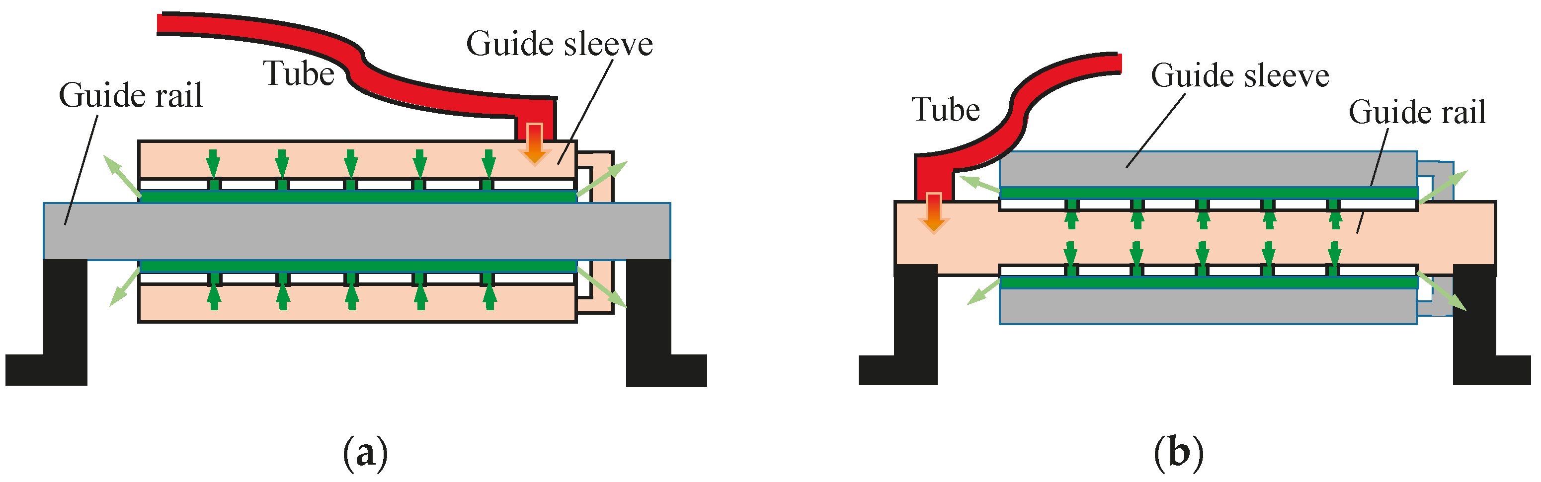
2.1. Working Principle

Mechanical crawling is common in most movement systems. While air bearings are regarded as having no crawling, for small systems, the electric wire in the motor and air tube of the guideway will still cause crawling and reduce accuracy. In principle, air bearings cannot provide bearing capacity without compressed air from the tube and an air-supply device. But compressed air can be supplied from the guide rail, meaning that the guide sleeve can be free of an air tube. As shown in Figure 2, the guide sleeve can avoid the traction force caused by an air tube if the guide rail can be supplied with high-pressure air, just like a motor with dynamic magnetic steel.

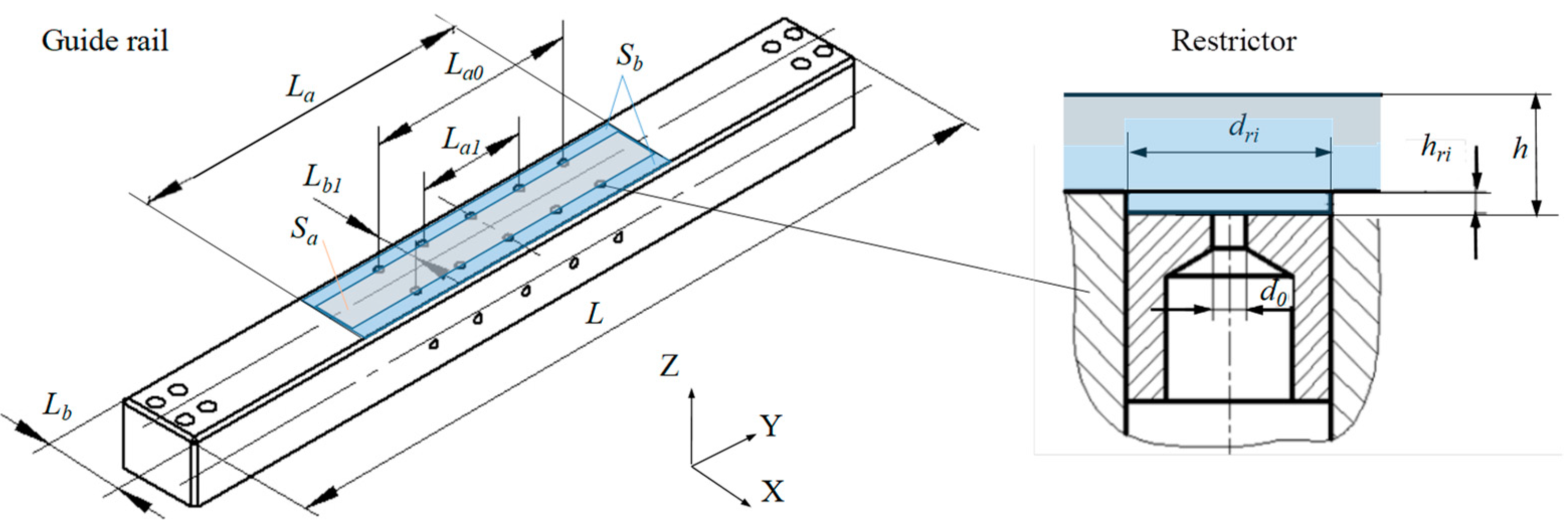
2.2. Structure and Model

The construction of compound restrictors is wholly concentrated on the guide rail, as shown in Figure 3. Although the guide rail has the length of L, the actual working proportion is determined by the length of the guide sleeve La. In order to simplify the computational domain of Sa and Sb, four assumptions can be formatted as follows:
Assumption 1.
No lateral flow along Y.
Assumption 2.
One-dimensional laminar flow along X in Sb.
Assumption 3.
No pressure gradient and consistent viscosity μ along Z.
Assumption 4.
Set status of adiabatic flow κ = 1.4 for compound restrictors and isothermal flow at other positions.
Based on these, the kinematic Equation (1) [1] can be simplified to Equation (2), in which the velocity of air flow along X, Y, and Z is, respectively, u, v, and w.
ρ u t + u u x + v u y + w u z = p x + x μ 2 u x 2 3 u x + v y + w z + y μ u y + v x + z μ u z + w x
p x = z μ u z
Create the indefinite integral of u. Then, bring in the boundary conditions of z, and integrate ρu on the outlet surface along X to obtain the outlet mass flow rate of Sb.
M o u t = ρ u d 2 S o u t = 2 L a 0 h ρ u d z = L a 1 2 μ d p d x ρ 0 h z z h d z = ρ h 3 L a 6 μ d p d x = h 3 L ρ a 6 μ P a d p d x p
Separate and integrate p and x of Formula (3). Substitute the import and export pressure status again when x = 0, p = Pd and when x = (LbLb1)/2, p = Pa.
P d 2 p 2 = 12 μ P a M o u t h 3 L a ρ a ( 0 x ) = 12 μ P a M o u t h 3 L a ρ a x
P d 2 P a 2 = 12 μ P a M o u t h 3 L a ρ a ( 0 L b L b 1 2 ) = 12 μ P a M o u t h 3 L a ρ a L b L b 1 2
Divide Formula (4) by (5) and transform it; the mathematical expression of pressure p in Sb can be given.
p = P d 2 2 x L b L b 0 P d 2 P a 2 1 2 = P d 1 2 x L b L b 0 1 P a 2 P d 2 1 2
The bearing capacity of the guideway W is the integration of p in Sa and Sb, and then minus the atmospheric pressure on the same area. In Formulas (7) and (8), β = Pd/Pa and Pd will be determined by P0, h, hri, and dri.
W = 2 L a 0 0 L b L b 1 2 p d x + 2 L b L b 1 2 L a L a 0 2 P a + L a 0 L b 1 P d L a L b P a   = 2 P a L a L a 0 L b L b 1 2 3 β 3 1 β 2 1 1 + L a L b 0 P a β 1
K h = d W d h = 1 3 N L a L a 0 L b L b 1 P a β 1 β 1 + 2 β 1 1 2 d β h d h 1 β 2 β 2 + 2 β 2 1 2 d β h d β 2
K θ = d W d θ
Formulas (7)–(9) could be directly used for traditional air bearings, but for the cableless one, the variation in W and its torque Mr caused by the geometric center deviating should also be analyzed.

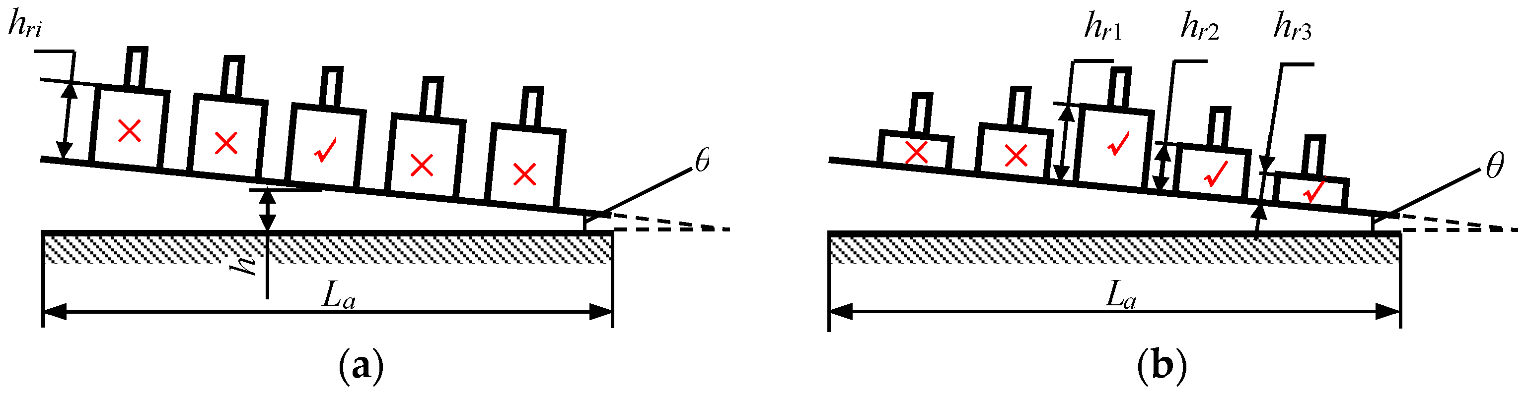
2.3. Work Distance Presupposition

The moving distance of guide sleeve without an air tube is restricted. The guide sleeve must cover all the orifices; otherwise, it will be overturned when the outermost restrictors are about to be exposed. To avoid this extreme situation, the work distance is set to Lcmax = 10 mm to meet Formula (10).
L c < L a L a 0 2

3. CFD Simulation and Structure Optimization

3.1. Simulation for Unified-Depth Recesses’ Air Bearing

When the guide sleeve moves along the y-direction, the asymmetry of the restrictors’ position will lead to the asymmetry of pressure distribution, as shown in Table 1. Due to the pressure homogenization effect [21,22], the bearing capacity W hardly changes unless it exceeds the range of Lcmax. But the rotational torque Mr continues to increase as the eccentricity value increases. The air film itself has a certain degree of stiffness and rotational stiffness, which can offset the rotational torque. But the cost is that the air film must produce spontaneous tilting, which is not desirable because it will reduce the straight motion accuracy [23]. We calculate the rotational stiffness of the air film at different moving distances l, which shows an inverse effect on the theoretical straightness error caused by rotational torque Mr, shown in Figure 4.
The rotational stiffness Kθ when the air film is tilted by 6 μm can be obtained by Formula (9). The Kθ values at different l are considered as the average ones, which are used to draw an approximate straight line of the rotational torque vs. straightness error. According to the rotational torque result in Table 1, the curve of the maximum straightness error Δmax vs. the moving distance l is drawn up in Figure 4. It can be seen that when l = 4~10 mm, the straightness error is about 6 μm, which is unacceptable for high-precision air bearings. Therefore, an improved structure needs to be invented to reduce the straightness error caused by an insufficiency of rotational stiffness.

3.2. Principle Structure of Gradient Depth of Recesses in Air Bearing

If the recesses’ depths are not equal, only one at most of the recesses can provide the maximum stiffness at its local film thickness. Usually, this recess is set in (or close to) the middle of the guide sleeve along La for balance, as shown in Figure 5a. But the downside is that its rotating arm is (or is close to) zero, providing such low rotational stiffness.
In order to improve the rotational stiffness, the recesses’ depths were set to the gradient, as shown in Figure 5b. The depths of hri are set to match the local film thickness h. This method has been experimentally validated by our previous research in ref. [3].
In order eliminate the influence of air volume changes, the recesses’ depths need to meet the following conditions:
5 h r i = h r 1 + 2 h r 2 + 2 h r 3
h r 2 = h r 1 h r 3

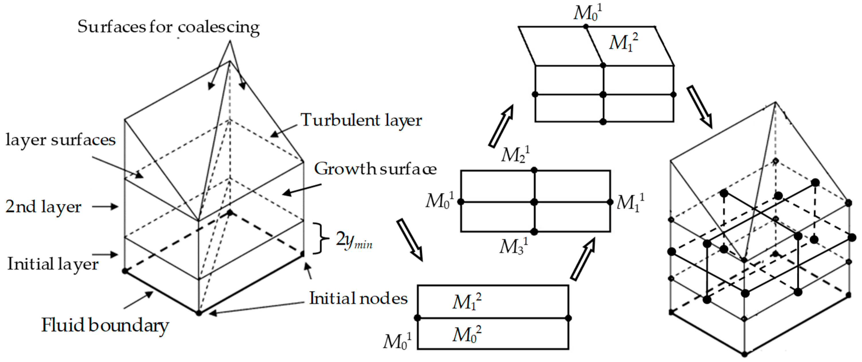
3.3. Numerical Solution of AFVM for Gradient-Depth Recesses

In order to solve the problem of non-convergence in the finite volume numerical solution of the compound throttling global flow field, the UDF (user-defined functions) in CFD method is proposed to capture and subdivide the mesh near the wall. As shown in Formulas (11) and (12), the dimensionless velocity u+ is modified as a mixed function of the linear law, which is associated with laminar flow, and of the logarithmic law, which is associated with turbulent flow. Then, the corrected u+ is incorporated into Formula (13) to obtain a new first grid height ymin, as shown in Formula (14).
u + = e Γ u l a m + + e 1 Γ u t u r b +
where Γ = C a y + 4 1 + C b y + , Ca = 0.01, Cb = 5;
y m i n = y m i n + μ / ρ u 0.058 R e 1 5 2
where u + = u u τ , y + = u τ μ y .
The structure of the guideway without an air tube is divided into hexahedral meshes according to the actual size parameters, and its initial boundary conditions (BCs) are shown in Figure 6.
BC1: Pressure inlet boundary. The pressure inlet boundary of the calculation domain is the outer edge of the throttle nozzle, with a total pressure of 4 atm (about 0.4 Mpa, σ = 4) for gas supply, a static pressure of 1 atm, a hydraulic diameter of the throttle nozzle aperture, a flow direction set perpendicular to the inlet boundary, and an initial turbulent re-flux intensity set at 9%.
BC2: Pressure outlet boundary. The pressure outlet boundary of the calculation domain is the outer edge of the gap between the air flotation shaft and the air flotation sleeve, with a total pressure of 1 atm and a hydraulic diameter of 2 times the air film gap. The flow direction is set perpendicular to the outlet boundary, and the initial turbulence re-flux intensity is set to 4%. The corresponding initial turbulent kinetic energy is set to k = 2.96 × 10³ m2/s2.
BC3: Smooth wall boundary. The smooth wall boundary of the computational domain is the upper boundary of the gas film gap, which is also used to calculate the mechanical properties of the guide rail on the air flotation working surface. The heat exchange is set to isothermal flow, and there is wall slip, so a strengthened wall treatment is adopted.
BC4: Microstructure wall boundary. The boundary of the microstructure wall in the computational domain is the lower boundary of the gas film gap, which includes the shallow cavity diameter, the width of the pressure equalization groove, and the depth parameters of these microstructures. Other settings are the same as BC3.
BC5: Symmetrical boundary of the air duct. The velocity and acceleration perpendicular to the boundary direction are zero, and the normal gradient in other directions on the boundary is zero.
BC6: Centrally symmetric boundary. Other settings are the same as BC5.
BC7: Adjacent area interface boundary. Two adjacent areas that share interface boundaries are divided into different grids, but it is necessary to ensure that some of the grid nodes overlap, such as the difference points.
BC8: Inner face boundary in the same area. The two parts of the same area that share inner face boundaries are divided into the same mesh method, so it is possible to achieve overlapping of all mesh nodes, such as point-to-point.
The result of the adaptive method for the boundary layer is shown in Figure 7.
In this method, the initial thickness of the layer is strictly divided according to 2ymin.
The surface along the thickness direction is the growth surface, so each hexahedron grid is composed of four growth surfaces and two layer surfaces.
Finally, the subdivided grid will move the position of the initial node up one layer for further subdivision.
Using the UDF in AFVM, the effects of recess depth on the carrying capacity and rotational stiffness of the air bearing are studied. This method has been experimentally validated by our previous research in ref. [24].
In UDF of FVM, a turbulence model is used to solve compressible 3D flow. The Cartesian coordinates are given as follows:
ρ u i x i = 0
ρ u i u j x j = P x i + x j μ u i x j + u j x i 2 3 δ i j u x ρ u i u j ¯ x j
x j u j C p p + ρ 2 u 1 2 + u 2 2 + u 3 2 = x j κ + C p μ t 0.85 T x j + u i μ + μ t u i x j + u j x i 2 3 δ i j u x
where ρ u i u j ¯ = 2 3 ρ k + μ t u i x i δ i j μ t u i x j + u j x i , with i = 1, 2, 3 and j = 1, 2, 3.
The turbulent eddy viscosity is given in Formula (18). The transport equations modeled for k and ε in the k-ε model are shown in Formulas (19) and (20), where S is the modulus of the mean rate-of-strain tensor defined as S = 2 S i j S i j . Finally, the rotational torque Mr of the guideway without an air tube can be found by summing the working face.
μ t = ρ C μ k 2 ε
t ρ k + x j ρ k u j = x j μ + μ t k x j + μ t S 2 ρ ε 1 + 2 k a c 2
t ρ ε + x j ρ ε u j = x j μ + μ t 1.2 ε x j + 0.43 ρ S ε 1.9 ρ ε 2 k + μ ε

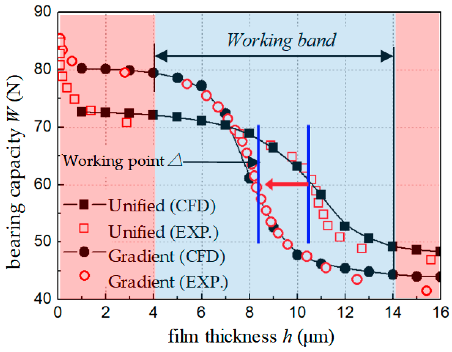
3.4. Calculation and Comparison

By calculation and comparison, a gradient-depth recess structure with significant improvements in rotational stiffness is obtained. That is, hr1 = 40 μm, hr2 = 30 μm, and hr3 = 15 μm. The simulation and calculation results are shown in Figure 8.
In principle, the structure of the gradient-depth recesses will increase both the rotational torque Mr by the eccentricity value and the rotational stiffness Kθ by the inclined value. But the growth rate of Kθ is faster than that of Mr. Figure 8 shows that the new structure’s straightness error is always smaller than 3 μm, which more than doubles the accuracy. This indicates that the guideway with gradient-depth recesses has obtained higher rotational stiffness at the same inclined angle. This characteristic makes it more difficult to overturn the guide sleeve, which is especially suitable for air bearings without an air tube.

4. Analysis and Discussion

For intuitive comparison, the UDF method was used to calculate the bearing capacity W with unified and gradient recesses. The experimental principle and equipment are consistent with the method described in ref. [3]. The comparison results are shown in Figure 9.
It can be seen that the bearing capacity W curves of the two types of bearing working faces calculated using the AFVM by UDF are consistent with the experimental results. Comparing the bearing capacity curves under different values of air film clearance h, it can be concluded that when h is small (1 μm ≤ h ≤ 4 μm) and large (h ≥ 14 μm), the bearing capacity W of the air flotation working face changes steadily with the air film clearance h. When h is medium (4 μm ≤ h ≤ 14 μm), it is the working zone with the air film thickness. Within this range, the bearing capacity W of the air flotation working face changes significantly with the air film clearance h. The h corresponding to the maximum slope of the W curve is the of the air film thickness at the maximum stiffness of the air flotation working face.
By comparing the two types of bearings without air tubes, it can be seen that the of the gradient recesses bearing obtained by the UDF method is around 9 μm, while the of the original unified recesses one is around 11 μm. Therefore, the working point of the air film thickness of the gradient recesses bearing is lower, reducing by at least 2 μm. At the same time, the air bearing capacity of the gradient recesses bearing is greater, the working band is wider, and the variation in bearing capacity within the working band is greater. This indicates that the idea of using UDF methods to adjust the working point of the air film thickness through the design of microstructure parameters, thereby changing the bearing capacity and stiffness performance of the bearing, is effective and feasible. The experimental results have verified the correctness of the CFD analytical hybrid design method based on AFVM.
The above experimental results indicate that the bearing capacity and stiffness of the gradient recess bearings’ working surface obtained by using the UDF design method based on AFVM are higher than those of the original guide air flotation working surface. The reason for this gain effect is that the design method proposed in this article considers the influence of microstructure parameters on the performance of the guide rail and adjusts the working point of the gas film thickness. The essence of this parameter adjustment is to establish a connection between microstructure parameters and throttling coefficients, and to correct the throttling coefficients in the analytical model. Through this experiment, it has been confirmed that the throttling coefficient varies with the gas film clearance, especially for small bearings without an air tube.

5. Conclusions

In order to reduce the influence of the traction force of air tubes and improve the rotational stiffness, we propose the technical concept of an air bearing without an air tube. The research in this article includes theoretical modeling, performance optimization, simulation analysis, and final comparative verification for an air bearing with gradient-depth recesses. The detailed results are as follows:
(1)
To avoid mechanical crawling and accuracy reduction from the air tube of the air bearing, we put forward a new structure of an air bearing without an air tube.
(2)
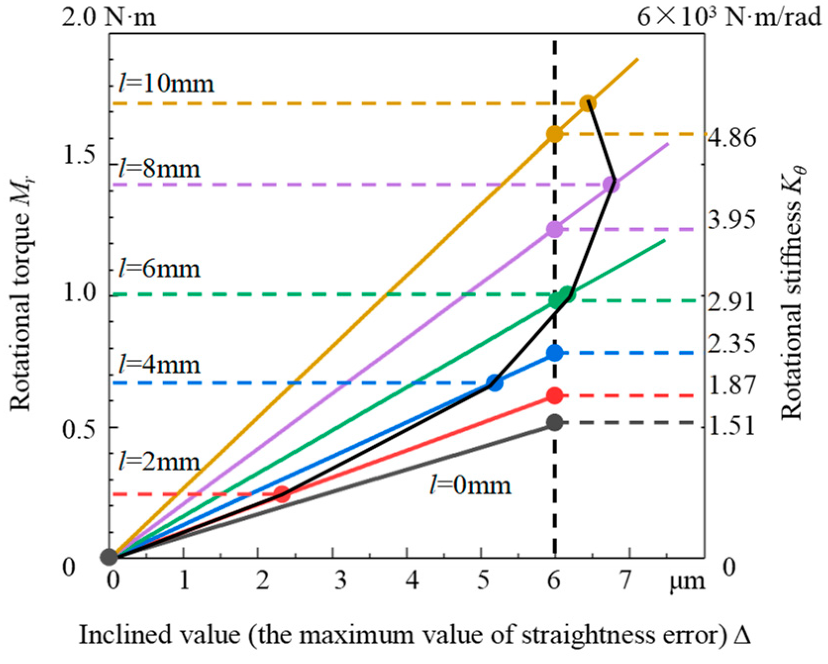
The mechanical performance model is established. The analysis results indicate that the air bearing without an air tube needs higher rotational stiffness Kθ to ensure the moving distance and linear accuracy.
(3)
The result of the theoretical analysis indicates that the gradient depth of recesses could improve the guideway’s rotational stiffness, which is verified by CFD investigations of AFVM.
(4)
The comparison shows that gradient recesses could reduce the straightness error by improving the rotational stiffness. The straightness error caused by rotational torque is always smaller than 3 μm, less than half of the original structure. The final actual error is even smaller because of the air film homogenization effect.

Author Contributions

Conceptualization, Z.W.; methodology, Y.C.; software, H.G.; validation, Y.C.; writing—original draft preparation, Z.W. and H.Q.; writing—review and editing, H.Q.; funding acquisition, Z.W. and Z.S. All authors have read and agreed to the published version of the manuscript.

Funding

This research was funded by the National Natural Science Foundation of China, grant number 52205042, and the Young Elite Scientists Sponsorship Program by CAST, grant number 2022QNRC001.

Data Availability Statement

The data presented in this study are available on request from the corresponding author.

Acknowledgments

Numerical calculation was supported by Beijing Engineering Research Center of Precision Measurement Technology and Instruments. The authors would like to thank all the reviewers who participated in the review.

Conflicts of Interest

The authors declare no conflicts of interest.

References

  1. Colombo, F.; Luigi, L.; Terenziano, R.; Trivella, A.; Viktorov, V. Design and Analysis of an Aerostatic Pad Controlled by a Diaphragm Valve. Lubricants 2021, 9, 47. [Google Scholar] [CrossRef]
  2. Yu, P.; Lu, J.; Luo, Q.; Li, G.; Yin, X. Optimization Design of Aerostatic Bearings with Square Micro-Hole Arrayed Restrictor for the Improvement of Stability: Theoretical Predictions and Experimental Measurements. Lubricants 2022, 10, 295. [Google Scholar] [CrossRef]
  3. Wen, Z.P.; Wu, J.W.; Xing, K.P.; Zhang, Y.; Li, J.A.; Tan, J.B. Design of Microstructure Parameters on a Small Multi-Throttle air bearing in Photolithography. Engineering 2021, 7, 226–237. [Google Scholar] [CrossRef]
  4. Zhang, Y.; Wu, J.W.; Xing, K.P.; Wen, Z.P.; Tan, J.B. Evaluation of measurement uncertainty of the high-speed variable-slit system based on the Monte Carlo method. Front. Mech. Eng. 2020, 15, 517–537. [Google Scholar] [CrossRef]
  5. Raghunathan, S. A Study of Reticle Non-Flatness Induced Image Placement Error in Extreme Ultraviolet Lithography. Ph.D. Thesis, College of Nanoscale Science and Engineering, Albany, NY, USA, 2010. [Google Scholar]
  6. Wu, J.W.; Wen, Z.P.; Cui, J.W.; Tan, J.B. A Wireless Cable Type Bidirectional Scanning Device. Chinese Patent CN109270805A, 26 February 2019. [Google Scholar]
  7. Wen, Z.P.; Wu, J.W.; Bin, D.E.; Zhang, Y.; Tan, J.B. A Slit Variable Aperture Based on Air Floatation Guidance. Chinese Patent CN108663797A, 7 May 2019. [Google Scholar]
  8. Wen, Z.P. Research on Design Method of Multi-Throttle Air Bearing with Recesswe and Grooves Based on Modified Discharge Coefficient. Ph.D. Thesis, Harbin Institute of Technology, Harbin, China, 2020. [Google Scholar]
  9. Maamari, N.; Krebs, A.; Weikert, S.; Wild, H.; Wegener, K. Stability and dynamics of an orifice based aerostatic bearing with a compliant back plate. Tribol. Int. 2019, 138, 279–296. [Google Scholar] [CrossRef]
  10. Zhang, J.; Han, D.; Xie, Z.; Huang, C.; Rao, Z.; Song, M.; Su, Z. Nonlinear behaviors analysis of high-speed rotor system supported by aerostatic bearings. Tribol. Int. 2021, 170, 107111. [Google Scholar] [CrossRef]
  11. Qi, L.; Liu, L.; Gao, Q.; Yao, Y.; Lu, L.; Gao, S. Investigation on the influence of structural rigidity on the stiffness of air bearing considering fluid-structure interaction. Tribol. Int. 2022, 173, 107658. [Google Scholar] [CrossRef]
  12. Feng, K.; Wang, P.; Zhang, Y.; Hou, W.; Cui, H. Novel 3-D printed aerostatic bearings for the improvement of stability: Theoretical predictions and experimental measurements. Tribol. Int. 2021, 163, 107149. [Google Scholar] [CrossRef]
  13. Ma, W. Study on Loading Characteristic of Parallel Micro-Channel Compensated Aerostatic Thrust Bearing. Ph.D. Thesis, Northeast Forestry University, Harbin, China, 2013. [Google Scholar]
  14. Wang, P.; Zhang, Y.; Feng, L.; Hou, W.; Wang, J.; Li, W.; Feng, K. Study on the pneumatic hammer phenomenon of aerostatic bearings based on the empirical mode method: Numerical and experimental analysis. Tribol. Int. 2023, 181, 108305. [Google Scholar] [CrossRef]
  15. Colombo, F.; Lentini, L.; Raparelli, T.; Trivella, A.; Viktorov, V. Dynamic characterisation of rectangular aerostatic pads with multiple inherent orifices. Tribol. Lett. 2018, 66, 512–521. [Google Scholar] [CrossRef]
  16. Li, Y.; Yin, Y.; Yang, H.; Liu, X.; Mo, J.; Cui, H. Modeling for optimization of circular flat pad aerostatic bearing with a single central orifice-type restrictor based on CFD simulation. Tribol. Int. 2017, 109, 206–216. [Google Scholar]
  17. Wu, Y.; Qiao, Z.; Chen, W.; Xue, J.; Wang, B. Evaluation and Application of an Engineering Calculation Method of the Static Performance of an Aerostatic Journal Bearing with Multiple Orifice-Type Restrictors. Lubricants 2021, 10, 332. [Google Scholar] [CrossRef]
  18. Du, J.J.; Zhang, G.Q.; Liu, T. Influences of Pressure-equalizing Groove on the Load Capacity of Externally Pressurized Gas Journal Bearings. J. Mech. Eng. 2012, 48, 106–112. [Google Scholar] [CrossRef]
  19. Wang, W.; Cheng, X.; Zhang, M.; Gong, W.; Cui, H. Effect of the deformation of porous materials on the performance of aerostatic bearings by fluid-solid interaction method. Tribol. Int. 2020, 150, 106391. [Google Scholar] [CrossRef]
  20. Wen, Z.P.; Wu, J.W.; Zhang, Y.; Cui, J.-W.; Tan, J.-B. Improving the rotational stiffness of compact air bearing by micro-structures optimization. IEEE Access 2019, 7, 55780–55787. [Google Scholar] [CrossRef]
  21. Mori, H.; Mori, A. Stabilizing Element for Externally Pressurized Gas-Bearing: 3rd Report, A Study of the Dynamic Characteristics. Trans. Jpn. Soc. Mech. Eng. 1967, 33, 2065–2072. [Google Scholar] [CrossRef]
  22. Powell, J.W. Design of Aerostatic Bearings; Ding, W.G., Lin, X.Q., Eds.; The Machinery Publishing Co., Ltd.: London, UK, 1978. [Google Scholar]
  23. Belforte, G.; Raparelli, T.; Viktorov, V.; Trivella, A. Discharge coefficients of orifice-type restrictor for aerostatic bearings. Tribol. Int. 2008, 40, 512–521. [Google Scholar] [CrossRef]
  24. Wen, Z.P.; Gu, H.; Shi, Z.Y. Key technology and design method of ultra-precision aerostatic bearing. Lubricants 2023, 11, 315. [Google Scholar] [CrossRef]
Figure 1. The evolution of reticle masking of photolithography machines in recent 20 years [6,7,8].
Applsci 14 07710 g001
Figure 2. Working principle of guideway. (a) Air tube on guide sleeve. (b) Air tube on guide rail (The direction of the arrows are the direction of the airflow).
Applsci 14 07710 g002
Figure 3. Structure, parameters, and computational domain of guideway without air tube.
Applsci 14 07710 g003
Figure 4. Structure, parameters, and computational domain of the guideway without air tube.
Applsci 14 07710 g004
Figure 5. The model of air film. (a) Unified-depth recesses. (b) Gradient-depth recesses [3] (√ means matched and × means not).
Applsci 14 07710 g005
Figure 6. Boundary conditions for initial mesh of guideway with recesses.
Applsci 14 07710 g006
Figure 7. Hierarchical structure and subdivision of boundary layer grids.
Applsci 14 07710 g007
Figure 8. The performance increasing of Mr (a) and Kθ (b) by gradient-depth recesses.
Applsci 14 07710 g008
Figure 9. Results of W of guideway working surface with air film clearance.
Applsci 14 07710 g009
Table 1. Guideway performance at different moving distances l (from 0 to Lcmax).
l
(mm)
Pressure DistributionBearing Capacity W (N)Eccentricity Value (mm)Rotational Torque (N·m)
0Applsci 14 07710 i001Applsci 14 07710 i00224200
2Applsci 14 07710 i0032492 − 1.02 = 0.980.244
4Applsci 14 07710 i0042584 − 1.34 = 2.660.686
6Applsci 14 07710 i0052706 − 2.28 = 3.721.004
8Applsci 14 07710 i0062688 − 2.73 = 5.271.412
10Applsci 14 07710 i00726410 − 3.43 = 6.571.734
Disclaimer/Publisher’s Note: The statements, opinions and data contained in all publications are solely those of the individual author(s) and contributor(s) and not of MDPI and/or the editor(s). MDPI and/or the editor(s) disclaim responsibility for any injury to people or property resulting from any ideas, methods, instructions or products referred to in the content.

