Article

Influence of Additives on Grinding Performance of Digital Light Processing-Printed Phenol Bond Grinding Wheels

Institute of Advanced Manufacturing (KSF), Furtwangen University, 78532 Tuttlingen, Germany
*
Author to whom correspondence should be addressed.
Appl. Sci. 2024, 14(17), 7711; https://doi.org/10.3390/app14177711 (registering DOI)
Submission received: 1 August 2024 / Revised: 22 August 2024 / Accepted: 26 August 2024 / Published: 31 August 2024
(This article belongs to the Section Additive Manufacturing Technologies)

Abstract

:
Resin bond grinding wheels are the most common grinding tools in the industry. Until now, all research on the additive manufacturing of resin bond grinding wheels has focused on commercially available acrylate resin. However, using a phenol-based bond to print resin-bond grinding wheels has been challenging for researchers and industries. In this study, a photo-curable phenol resin bond grinding wheel was introduced for the first time, offering advantages such as lower cost, high thermal resistance, and good mechanical properties. To enhance the grinding performance of the printed wheels, various additives, such as copper, glass fiber, and carbon fiber, were incorporated into the composition. Different on-machine and out-of-machine measurements, such as force, tool wear, dimensional accuracy, and optical microscopy measurements, were conducted to investigate the grinding performance of the printed wheels. The results demonstrate that printed grinding wheels have strong potential in grinding applications, which was more prominent for the bond reinforced by glass fibers, providing improved mechanical properties (up to 50%), wear resistance (up to 75%), and higher dimensional accuracy (up to 11%).

1. Introduction

The importance of grinding as a finishing process step originates from its dimensional accuracy, a wide range of machinable materials, and good surface finish. Grinding wheels consist of the bond and the abrasives. The combination of these components determines the properties of the grinding wheel.
There are three main bond types: vitrified, metal, and resin. Each has its advantages and disadvantages. The resin bond has low process forces and self-sharpening properties and is the second most common bond type for grinding wheels [1]. The tool life and wear of grinding tools depend on various factors, such as the mechanical properties of the tool (strength and fracture toughness), the interfacial adhesion between the matrix and abrasives, and thermal conductivity [2].
Various resin types exist, each with distinct properties. The type of resin bond is selected based on the application [3]. These resin bonds can be categorized as phenolic resin bonds, polyimide and polyamide bonds, and epoxy or urethane resin bonds. Resin-bonded grinding wheels are manufactured through thermal pressing. This process involves filling a mold with a mixture of resin and abrasives and then pressing it under a high temperature for an extended duration [4]. This process is quite time- and energy-consuming.
Additive manufacturing (AM) has gathered attention across different fields of engineering [5]. AM presents a more versatile and resource-efficient approach to grinding wheel production. The layer-by-layer manufacturing inherent in AM enables the production of grinding wheels with internal or external structures without additional expenses or manufacturing processes [6,7,8]. This allows the elimination of molds, which also allows greater flexibility in the grinding wheel design, which consequently reduces the costs and development time [6,9]. Finally, the AM method needs less energy and time for grinding wheel production compared to the thermal-pressing method [10,11]. Barmouz et al. [7,9] reported that using AM could contribute to more easily improving the bond strength and finding the efficient bond material for resin bond grinding wheels. They printed resin bond grinding wheels with different abrasive grains, including SiC and diamond in different concentrations, to understand the effect of each parameter on the grinding performance. They also investigated the influence of surface structures and cooling channels on the grinding performance of the printed wheels [8].
In an experimental study, Yang et al. [12] employed selective laser sintering (SLS) to fabricate metal-bonded grinding wheels with a regular distribution of abrasive grains. It was asserted that the fabricated wheels were capable of withstanding high grinding forces without significant diamond grain pull-out. The fabrication of porous metal-bonded grinding wheels using selective laser melting (SLM) with varying structures (octahedron, honeycomb, and solid) was documented by Tian et al. [13]. The findings of the study indicate that grinding wheels produced via SLM exhibit excellent dressing and self-sharpening capabilities, along with high compressive grinding performance. Furthermore, the quality of the bonding between the abrasives and matrix was found to be entirely satisfactory, with the formation of chip flutes around the abrasive grains. Denkena et al. also produced metal-bonded grinding wheels (NiTi diamond composites) using SLM [14]. The results of the study demonstrate that the matrix was capable of maintaining a firm grip on the abrasive diamonds when a scratch test was conducted on tungsten carbide using fabricated grinding wheels. The impact of additive particles on the functionality of grinding wheels produced via stereolithography was examined by Qiu et al. [15]. Their findings indicate that the incorporation of additive particles, including Al2O3, SiO2, and SiC, enhanced the tensile strength of the composites. However, this resulted in a concomitant reduction in the shear strength of the composites.
Pure resin bond grinding wheels find almost no use in the industry due to their low crack resistance, strength, and hardness. In order to improve their mechanical properties, fillers/additives, like fibers, solid lubrication, SiC, or metals, can be added. These additives can provide more strength, porosity, lubrication, and better thermal conductivity [2,16,17]. Fu et al. [18] showed how the properties of resin can be influenced by additives. They also showed that the impact of the additives is dependent on the particle concentration and size. In addition, they state that one of the most important factors for additively manufactured plastic composites is the adhesion forces at the interface between the particles and the matrix, as well as the distribution of the particles in the matrix.
This work investigates the influence of fillers, such as glass fibers, carbon fibers, and copper particles, on the grinding performance of phenol-bonded grinding wheels, as one of the challenges in grinding wheel production is the determination of the influence of additives on grinding behavior. In this work, photo-curable phenol resin was used for the first time as a bond material. There is only a limited number of reports (according to the authors’ knowledge) about identifying the influence of additives on mechanical properties and grinding performance. Flat grinding processes were carried out on an aluminium plate with specified grinding parameters. To analyze the grinding performance, the normal and tangential force (Fn and Ft), as well as the topography, morphology, and wear of the grinding wheel surface, were measured. This study will make a very appreciable contribution to grinding performance since there is limited data available in this area.

2. Materials and Methods
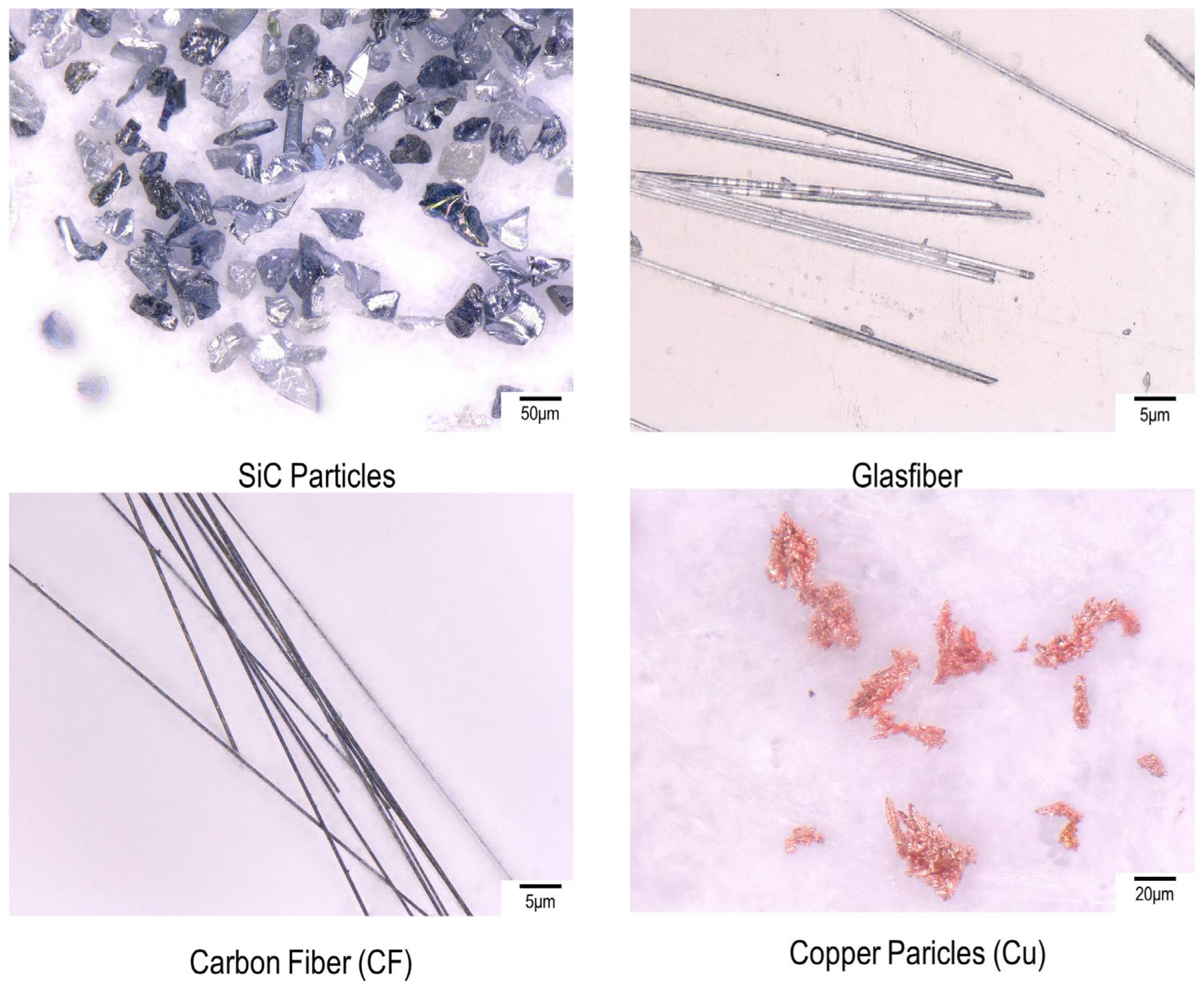
2.1. Materials

Different materials and particles were used in this work (see Figure 1). Their sizes are displayed in Table 1. For the bond, a phenol resin was used. Phenol resin is a thermosetting plastic that cannot undergo curing through UV light. In a joint research project, the University of Osnabrück developed a modified phenol resin that can cure under UV radiation. Polymerization is made possible by a free-radical photoinitiator system. Through printing, a partially hardened part is produced, which has to be cured in the oven.
Three common additives for grinding wheels were chosen for this work. Glass fibers and carbon fibers were chosen because of their high strength and chemical resistance [19]. Copper was selected in order to increase thermal conductivity [20].

2.2. Printing and Post-Processing Process

A laboratory-scale digital light processing (DLP) machine (Totem3D) with a 250 W UV power source was employed to produce the grinding wheels. To achieve a homogeneous mixture, the bond resin, abrasives, and an anti-sediment agent were combined in a single-step process. The mixture was stirred for 20 min using a 200 W electric mixer equipped with a stainless-steel stirring rod, operating at a maximum speed of 3000 RPM. The mixtures with fibers were additionally dispersed with an ultrasonic disperser for 10 min (see Figure 2). The grinding wheel specifications are listed in Table 2. The post-curing process was carried out for two hours at 180 °C.
For mechanical characterization, four tensile samples were printed according to ASTM-D638-14. Their composition is listed in Table 3. The same process of printing grinding wheels was applied for printing the tensile samples.
Figure 3 presents the results of the optical microscopy examination of the printed grinding wheel surfaces, indicating the satisfactory dispersion of the abrasive grains and fillers within the wheels. The separation states of the glass and carbon fibers (see Figure 3b,c) are deemed satisfactory, as no significant agglomeration was observed in the microstructural examinations. In addition, for the grinding wheel filled with copper particles, it could be seen that the copper particles were well dispersed between the abrasive grains.

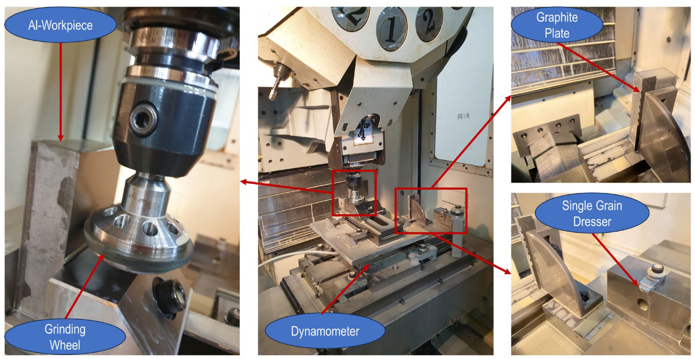
2.3. Grinding Process

The grinding test was performed on a CNC machining center (Müga R4530). Figure 4 shows the experimental setup. The grinding wheels were dressed with a single-grain diamond dresser. After that, the workpiece was ground with different grinding parameters (shown in Table 4). The grinding parameters were determined based on several initial tests on the workpiece to find the optimum parameters to evaluate the influence of the bond properties during which the material removal rate was kept constant, while the depth of cut and feed rate changed accordingly. During the dressing and grinding processes, an emulsion was used as a cooling fluid. An aluminium plate was selected as the optimal material for the workpiece due to its compatibility with the SiC abrasives utilized in the production of grinding wheels. The use of aluminium plates allows a more pronounced demonstration of the variations in grinding wheel performance.

2.4. Measurement

To assess the grinding process and the performance of the grinding wheels with different additives, various in- and out-of-process measurements were conducted. The grinding forces were measured during experiments using an ME systems force dynamometer. It was securely fixed to the machine table. The workpieces were clamped with a standard clamp installed on the dynamometer (Figure 4).
To determine the wear of the grinding wheel, a thin graphite plate was ground in fixed intervals. By measuring the distance between the ground profile steps, the changes in the grinding wheel diameter were calculated. The real depth of cut was determined based on depth differences between the ground surfaces and adjacent workpiece surfaces, measured using a contour measuring device (Hommel-Werke: T-8000, Germany).
Following workpiece machining, surface roughness was measured using an optical roughness measuring device (3D-Profilometer VR 6200 (Keyence), Germany) employing a multi-line strategy with an average of 10 lines. The measurement was carried out in accordance with DIN EN ISO 21920.
A tensile test machine was utilized to derive the mechanical properties of both the pure resin and the composite wheels through tension experiments conducted at a rate of 2.5 mm/min. The tensile test samples were prepared according to the D638-14 standard. To enhance data reliability, each measurement was repeated three times, and the reported values included the average along with the calculated error bars.

3. Results

This section discusses the mechanical properties and grinding performance of DLP-printed grinding wheels. First, the mechanical properties of diverse compositions were evaluated through tensile tests. After that, the grinding experiments were analyzed and discussed.

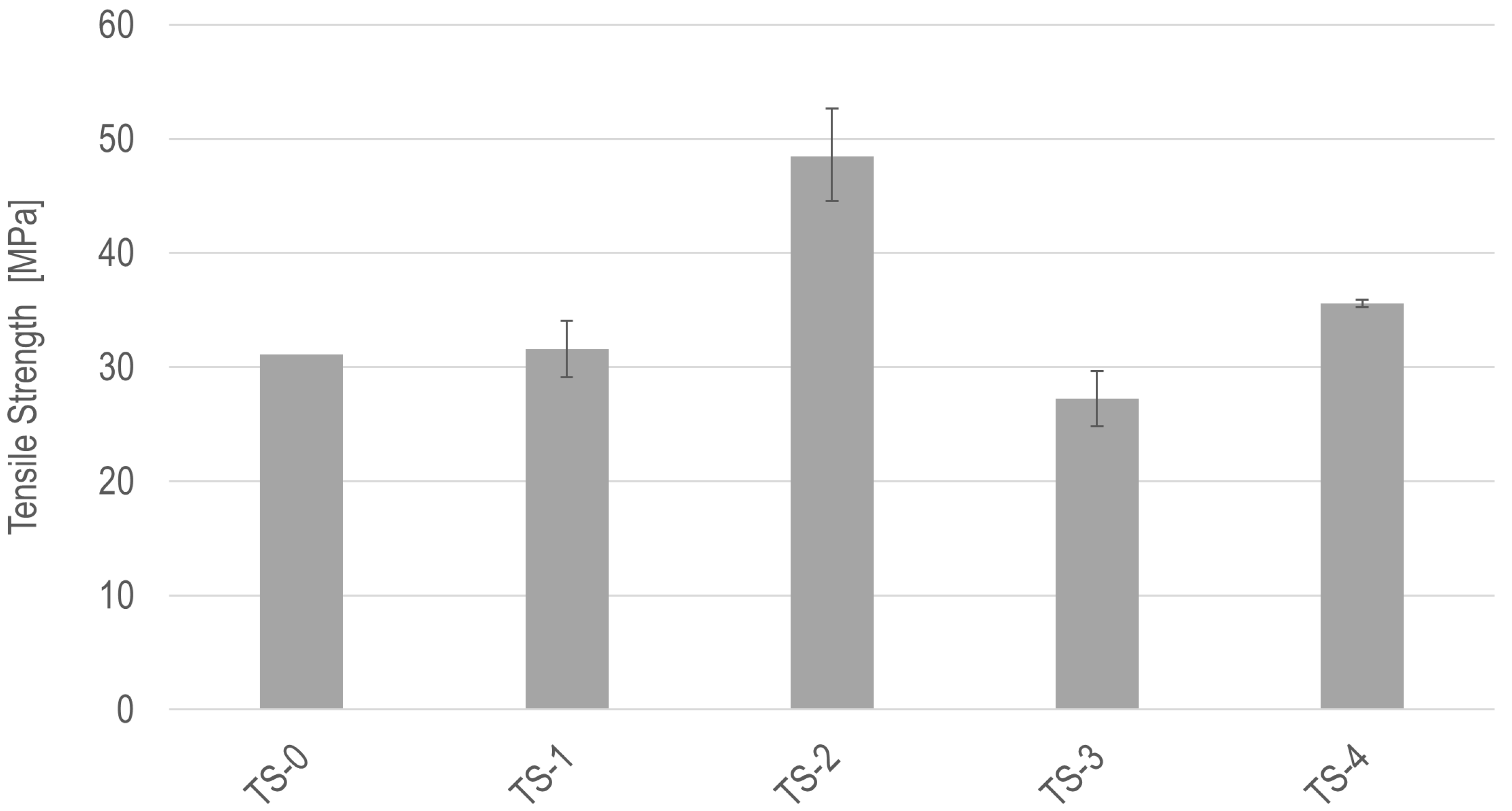
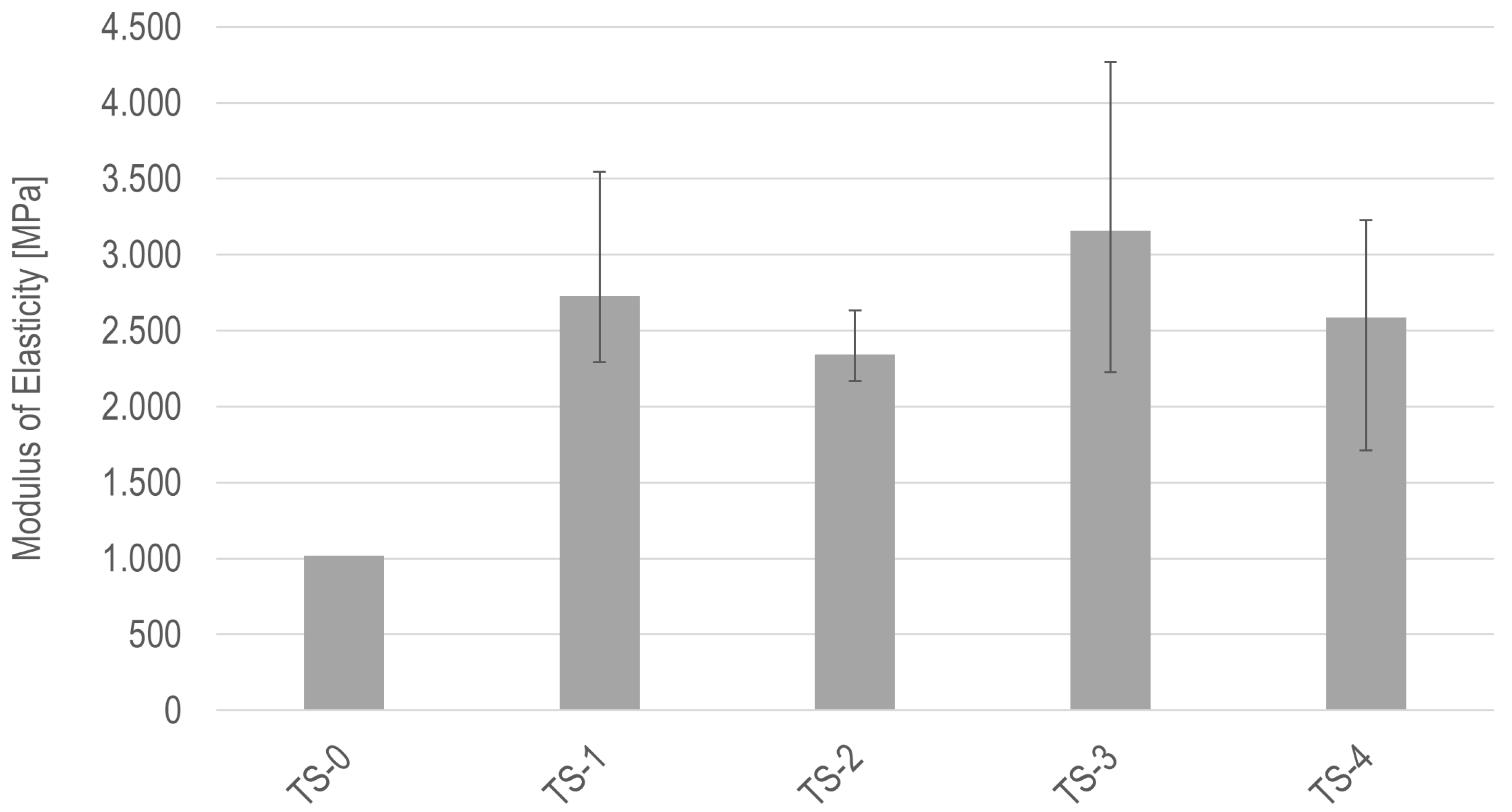
3.1. Mechanical Properties of Grinding Wheels

In order to see the influence of the different additives, tensile tests were carried out. Figure 5 displays the average mechanical properties of the printed samples. As seen in this figure, the pure resin has a strength of around 30 MPa. By adding the abrasive grains (SiC), an insignificant change in strength value was determined. The addition of glass fibers (GFs) with a mass fraction of 1.2 w% to the resin–abrasives composite (TS-2) led to an increase of over 50% in strength. The increase probably comes from the significantly higher tensile strength of the glass fibers with a high aspect ratio by which polymer–fiber entanglement happens, thereby improving the load-bearing ability of the composite. In contrast, when adding carbon fiber (CF), the strength decreased by over 10% (0.6 w% CF) despite its higher tensile strength, which could be attributed to the different utilized fiber lengths. Joseph et al. [21] explained the reduction in strength for compounds with shorter fibers: the short fibers detach more easily from the matrix than the long fibers, which leads to failure at low stresses. Adding 5.5 w% of copper led to an increase in strength of roughly 15% compared to TS-1. The main reason for this result is the strengthening effect of particles caused by the existence of copper particles preventing the mobility of the polymeric chains during the tensile test, by which the load needed for sample breakage is enhanced.
In addition to the tensile strength, the modulus of elasticity was determined from the stress–strain curve. The modulus of elasticity is displayed in Figure 6. The pure resin shows a modulus of elasticity of 1017 MPa. By adding abrasive grains (SiC) 170% increase in the elastic modulus value was observed. This is probably due to the high elastic modulus of SiC. Furthermore, abrasive grains can serve as a barrier to material flow, leading to increased stress concentration and a higher probability of crack initiation between the bond and grain, resulting in reduced tensile strain. The addition of glass fibers with a mass fraction of 1.2 w% led to a reduction in the modulus of elasticity of 15% in comparison with the PF/SiC compound. The addition of carbon fibers with 0.6 w% content led to an increase of 17%. The E-modulus was decreased with the addition of 5.5 w% copper by 5% less than the PF/SiC modulus of elasticity. After adding additives to the resin–abrasives mixture, the modulus of elasticity barely changed. Fu et al. [18] explained this phenomenon as a result of the non-homogenous distribution of particles in the resin matrix.

3.2. Grinding Experiment

3.2.1. Dressing Operation

Figure 7 shows the surface morphology of the grinding wheels after the dressing operation. Based on these images, all GWs seem to have a similar microstructure and a similar level of grain protrusion after the dressing operation. The lack of differences in the GW surfaces could be a result of the small added percentage of additives and the same fine dressing parameters. By inspecting the GW surfaces in Figure 7, it can be seen that the majority of the surfaces consist of resin or abrasives. In addition, due to their small concentration and the relatively small analyzed area, it is not possible to determine the homogenous distribution of the additives for GW-2 and GW-3. For GW-4, the figure indicates a fairly homogenous distribution of copper without greater agglomeration.

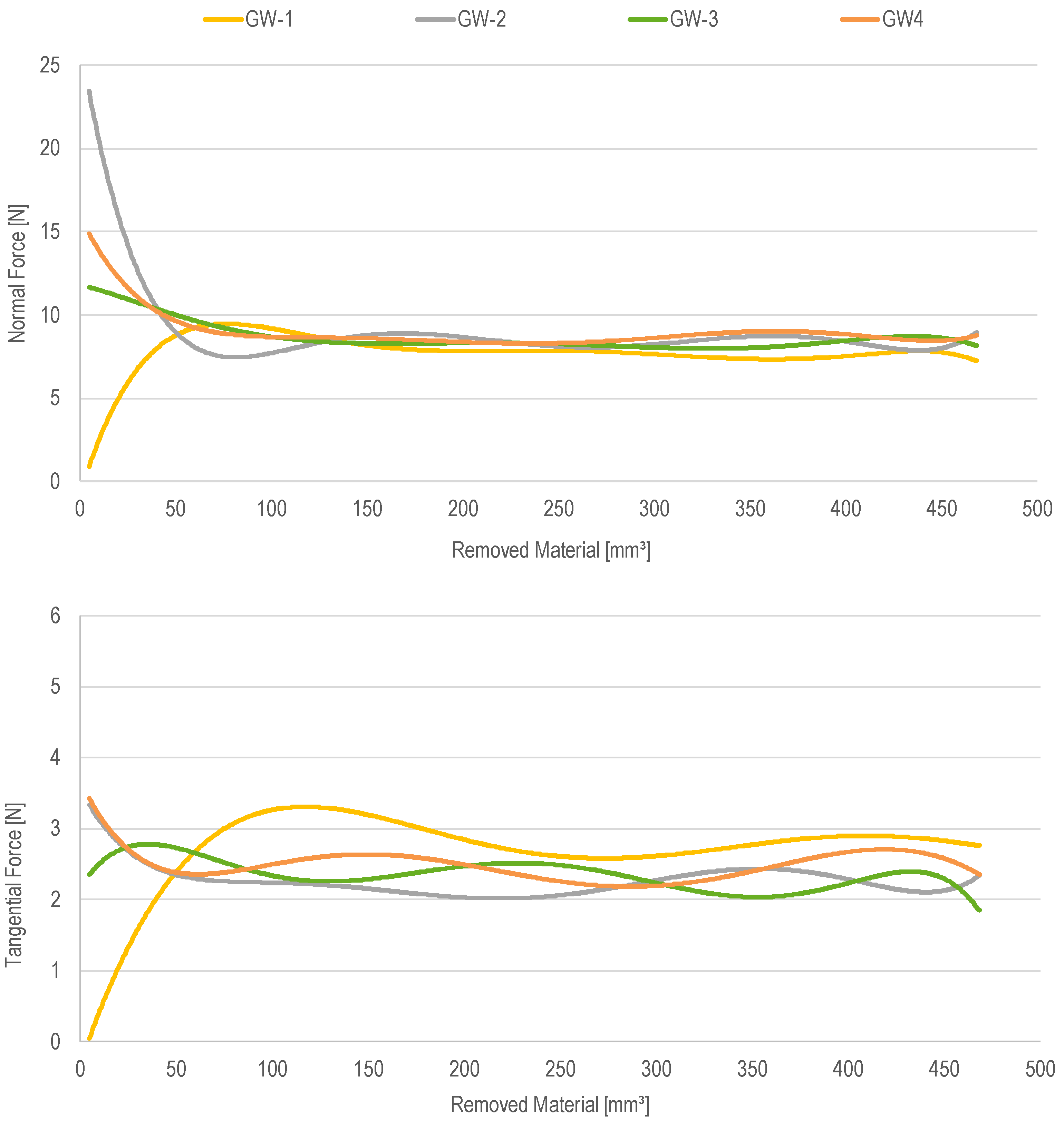
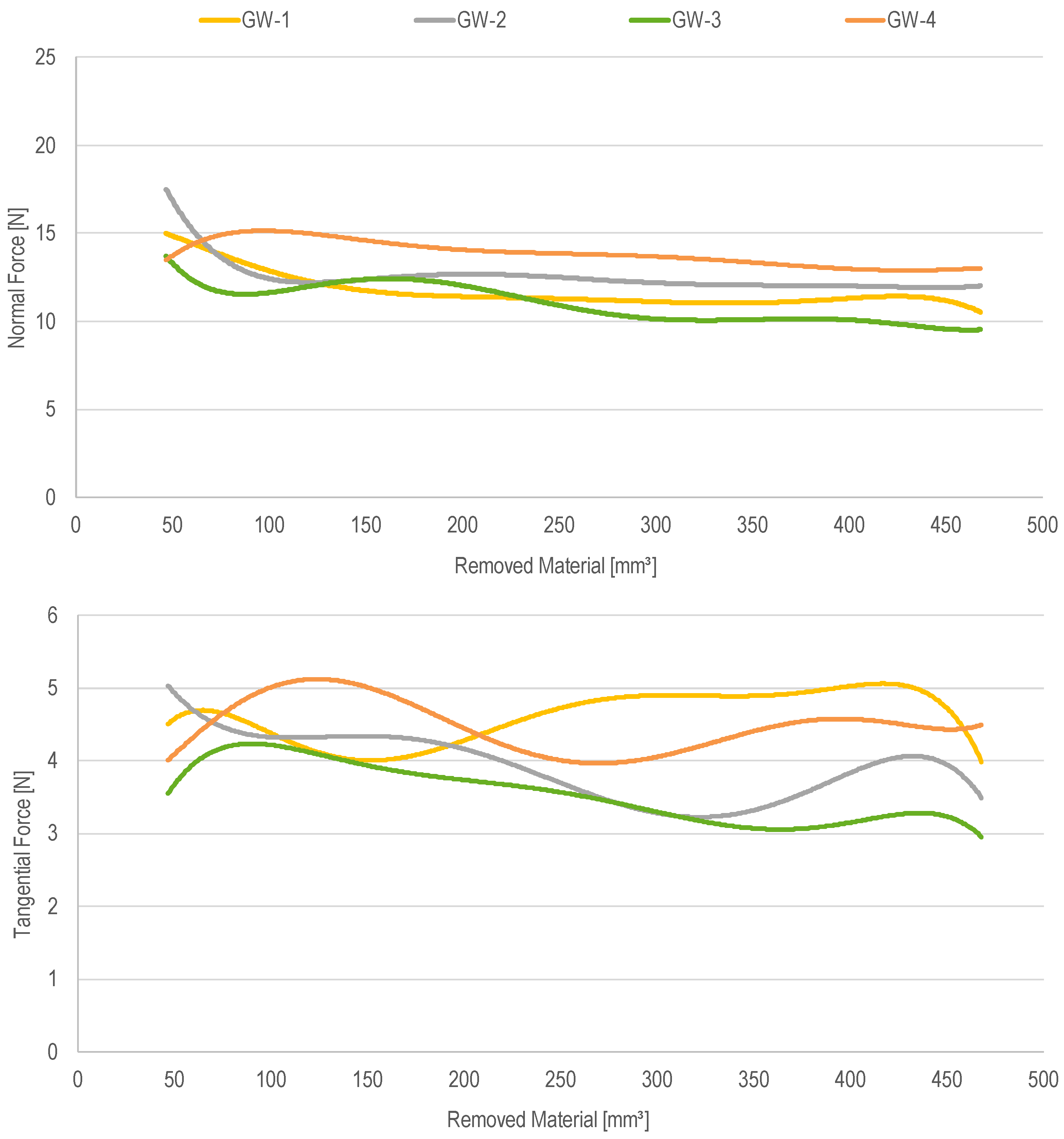
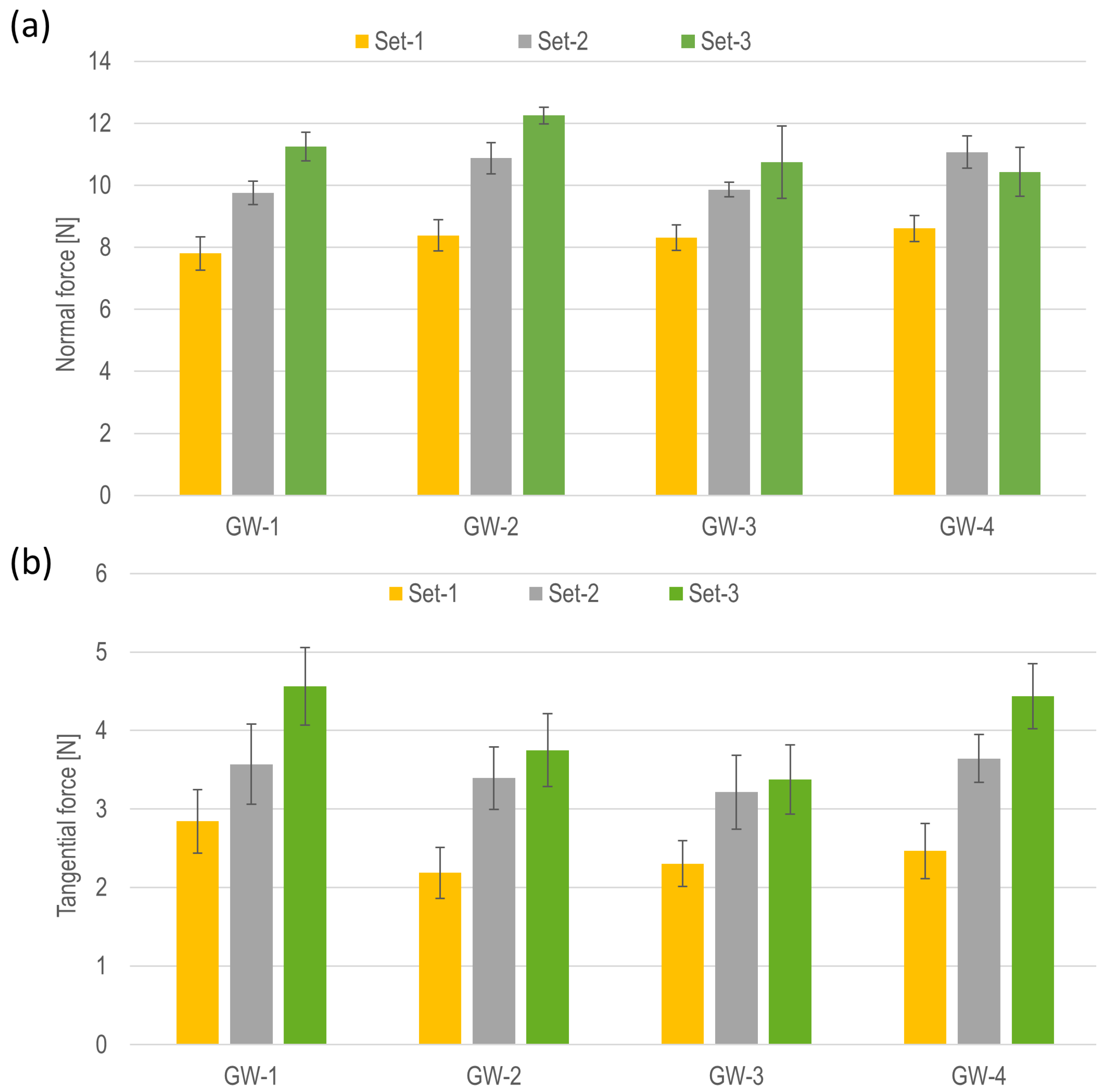
3.2.2. Grinding Forces

This section shows the results of the forces during the grinding process with different grinding process parameters (see Table 4) and different additively manufactured resin-bonded grinding wheels (see Table 2).
Figure 6 displays the force values during the grinding operation on the Al workpiece with parameter set 1. In general, all GWs have a grinding-in phase after dressing. This was observed through the unstable and rapid changing forces at the beginning of the grinding process. This could be the result of the influence of the dressing parameter effect on the different bond properties. For example, in Figure 8, you can see that GW-2 has the highest force at the beginning. This could be due to protruding grains with better grain retention. In comparison, there is GW-1, where the grains detach more easily and fall out after making first contact with the workpiece. It was observed that after the initial phase of grinding, the GWs developed a fairly stable force level, indicating that the microstructure of the GWs finds a stable configuration.
It was observed that the normal force (Fn) for all GWs reached roughly the same force after the removed material volume of 120 mm3. The tangential (Ft) force varied for all GWs between 2 and 3 N. The fluctuating Ft indicates that there could be self-sharpening. To explain this phenomenon, when the grains become dull or drop out, the grinding forces begin to rise, leading to an increase in heat concentration and localized stress. In this state within the cutting zone, the bond starts to wear out and grain sharpening occurs, causing the forces to subsequently decrease.
Figure 9 illustrates the grinding force for grinding with parameter set 2. In comparison to parameter set 1, the initial phase for all GWs was similar to the trend discussed earlier. The higher forces and larger contact area covered the differences in bond properties. The fluctuating tangential force of GW-1 indicates a constant flattening and sharpening of the wheel. In contrast, the force of GW-2, 3, and 4 stayed at the same level after roughly 250 mm3, which indicates the start of the stable grinding region.
Figure 10 illustrates the grinding force for grinding with parameter set 3. The grinding forces showed the most variation between the GWs compared to the other parameter sets. Additionally, the initial phase of grinding represents a significant force reduction since the higher depth of cut caused a smaller chip thickness, providing less frictional contact between the wheel and the workpiece. GW-1 has the lowest normal forces but high tangential forces, which could be indicative of higher tool wear and tool–workpiece frictional contact. GW-2 and 3 have low normal forces and fairly low tangential forces, which indicates a good balance between tool wear and material removal. GW-4 has the highest normal forces, which is attributed to the higher pressure and rubbing contact in the contact zone.
In Figure 11, the average normal and tangential forces for the stable region of the grinding process for all grinding wheels are displayed. It can be seen that with the increase in the depth of cut, the cutting forces increase. For shallow grinding (parameter sets 1 and 2), GW-1 has the lowest average normal forces. For parameter set 3, GW-3 has the lowest forces. Although a higher depth of cut brings about smaller uncut chip thickness, it causes a higher material removal rate, creating higher thermal and mechanical stresses in the cutting zone. According to this explanation, the higher depth of cut could lessen the grinding force by reaching smaller uncut chip thickness and increase the force values by inducing higher material removal rates. On balance, the rise in force levels between the parameter sets in this study comes from the higher material removal rate resulting from the higher depth of cuts. As a result, it is assumed that the change in the forces (Fn and Ft) in a parameter set must come from its bond properties and capability to hold grains.

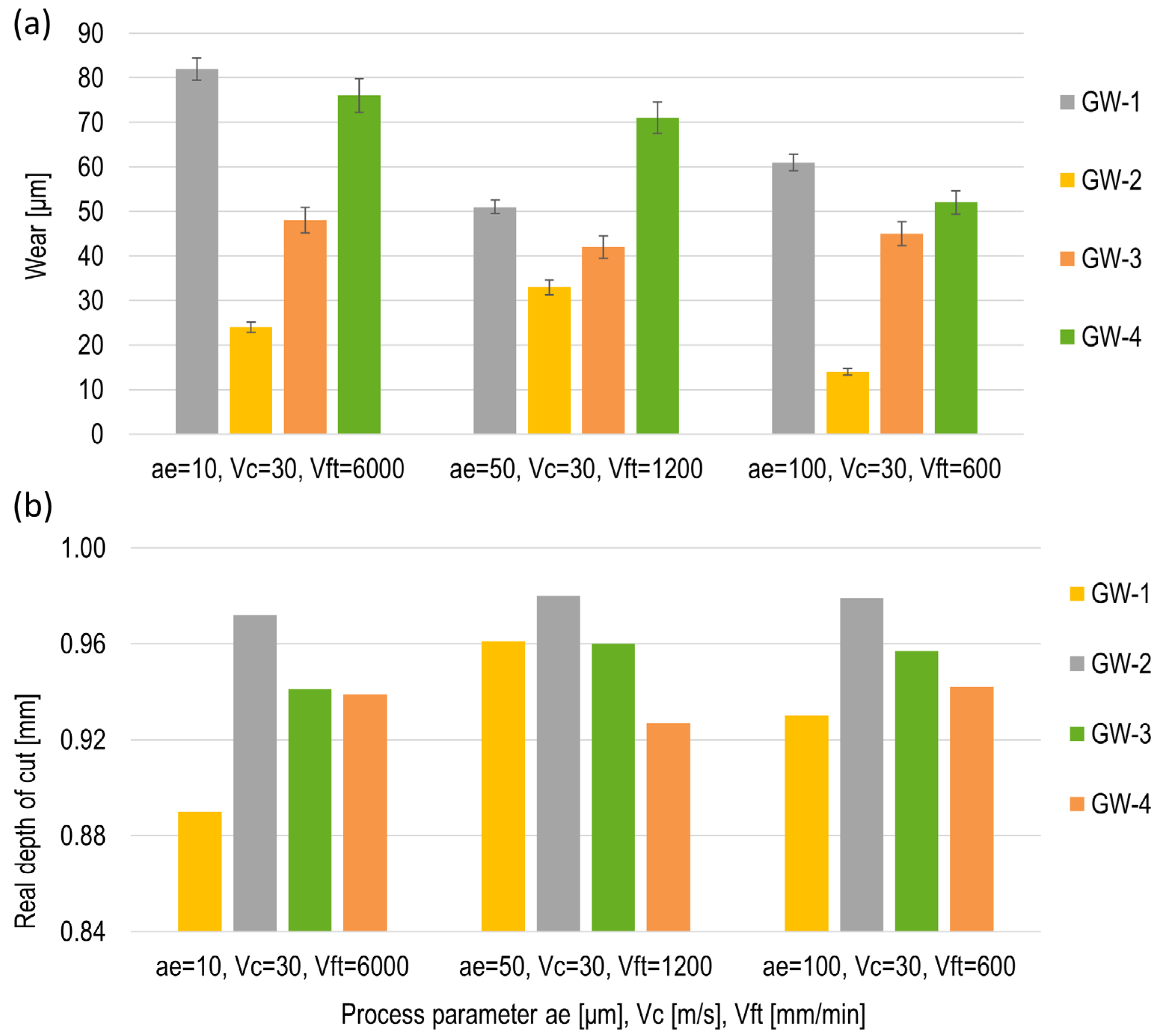
3.2.3. Real Depth of Cut and Tool Wear

This section analyzes the wear of the grinding wheels after grinding with different grinding parameters. Since the grinding operation typically represents one of the final stages in the parts manufacturing process, the capability of grinding wheels depends on factors such as tool life and dimensional accuracy.
According to Figure 12a, when grinding with a low infeed (parameter set 1), GW-1 shows the highest wear. The other examined grinding wheels represent the reduced tool wear values of up to 70%, 41%, and 7% for GW2, GW-3, and GW-3, respectively, compared to GW-1. The lowest wear was achieved when grinding with GW-2, which is mainly attributed to the higher mechanical properties of this bond compared to the others, increasing the grain retention ability of the bond. An almost similar trend of tool wear was observed when a higher infeed rate was utilized to perform grinding operations. It is seen in this figure that GW-2 represents the highest resistance to wear by representing a 26% less tool wear value compared to GW-1. During grinding with the highest infeed and lowest feed rate (parameter set 3), the wear of the grinding wheels still shows the same trend as when grinding with the lowest infeed (parameter set 1). However, the measured wear values indicate a slight reduction compared to the grinding condition in set 1. It is worth mentioning that GW-2 offered the lowest value of tool wear with a 75% reduction compared to GW-1.
A decremental trend in tool wear was observed by increasing the depth of the cut. This probably comes from the higher tool compression along with the smaller uncut chip thickness. Indeed, when the pressure between the workpiece and GW increases, the bond gets pushed back, resulting in higher grain contact with the workpiece, which leads to cutting instead of rubbing. On the other hand, smaller uncut chip thickness causes less loading on the grinding wheels. GW-4 wears similarly to GW-1 since the copper particles influence the thermal conductivity rather than the strength of the bond.
Examination of the actual cutting depth confirms the wear measurements. Indeed, the tool wear values closely mirror the remaining uncut portions of the real depth of cut, with only a small discrepancy between the theoretical and measured real depth of cut (see Figure 12b). The deviation could be the result of tool deflection or compression.

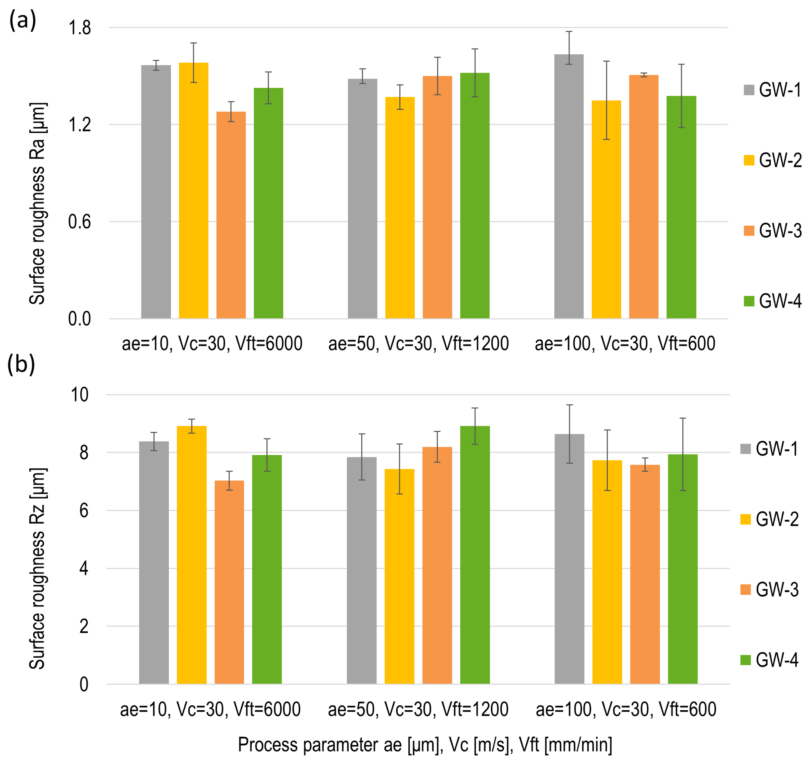
3.2.4. Surface Roughness

In this section, the surface roughness of the workpiece after the grinding process with different grinding parameters is analyzed. The measured surface roughness values are displayed in Figure 13.
The results of the surface roughness of the ground surface under parameter set 1 show that the Ra values for GW-1 and GW-2 are approximately the same. In comparison, the ground surface of the workpiece exhibits lower Ra values when grinding with GW-3 and GW-4. Applying parameter set 2 for the grinding operation decreased the Ra value of GW-2 significantly, making it the lowest obtained surface roughness. In addition, it was observed that the ground surface with other grinding wheels represents almost the same value of Ra under the grinding parameters in set 2. Following the grinding operation by utilizing parameter set 3 reduced the Ra values of the ground surface except for GW-1. It was also demonstrated that the lowest value of the surface roughness still belongs to the ground surface with GW-2.
The increase in surface quality when using GW-2 could come from the higher grain retention due to its better mechanical strength. Indeed, higher grain retention prevents grains from dropping out under cutting forces, creating a higher chance for the grains to break rather than fall out. This could lead to emerging broken grains with flat surfaces on the grinding wheel surface, providing a better surface quality. This phenomenon can also be seen in Ft since the higher values indicate a sharper GW due to the chip formation forces instead of showing compressive force in the normal direction.

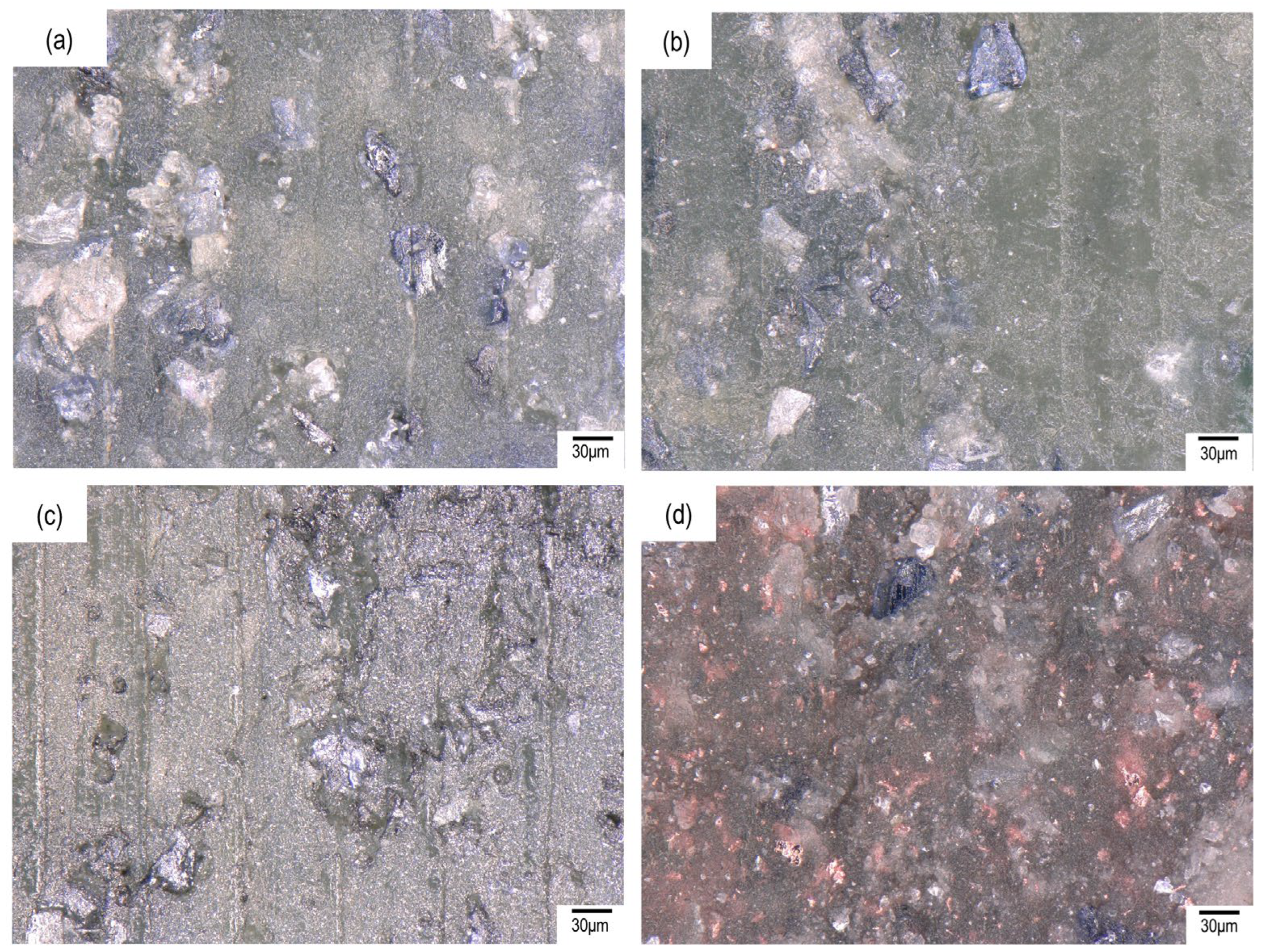
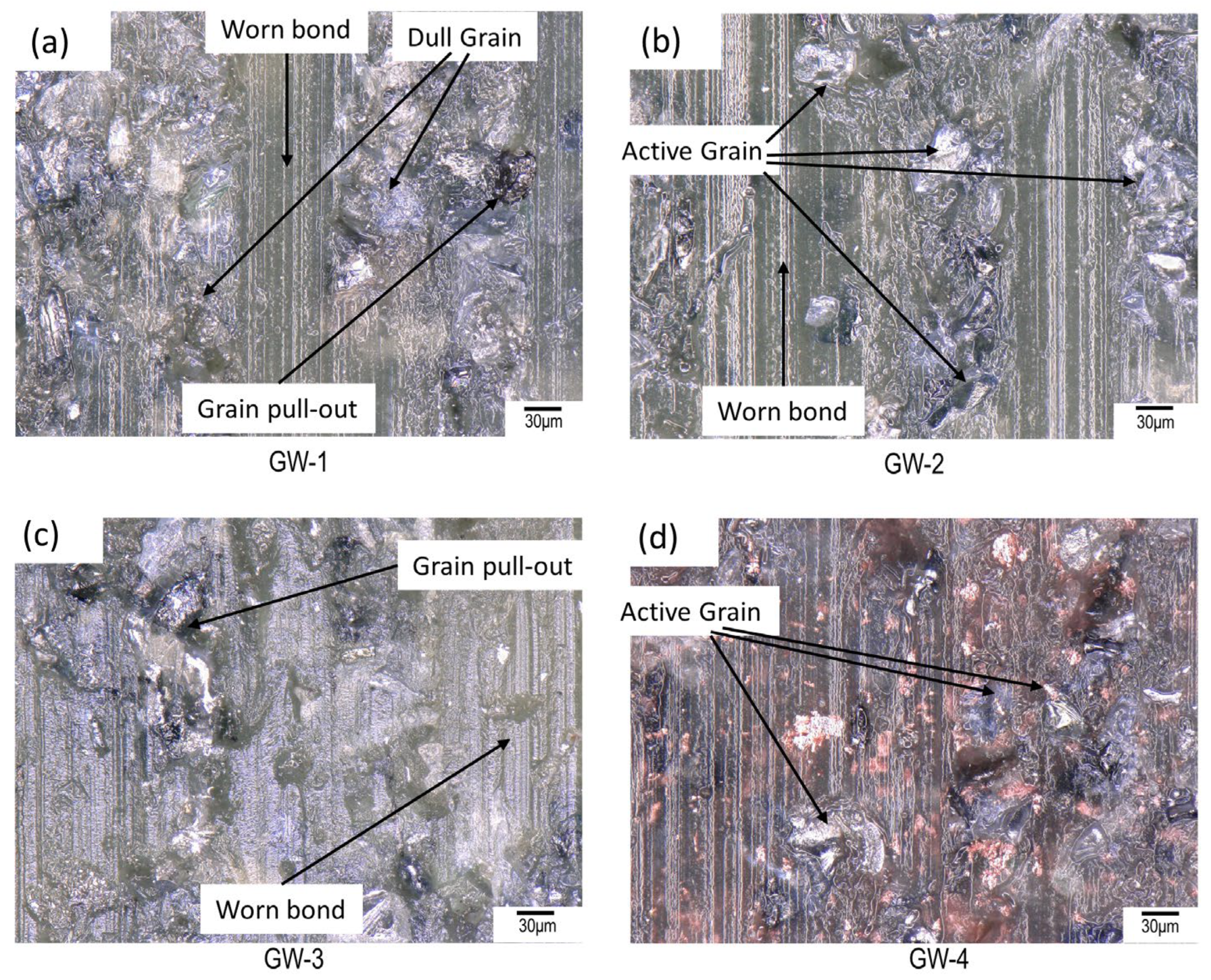
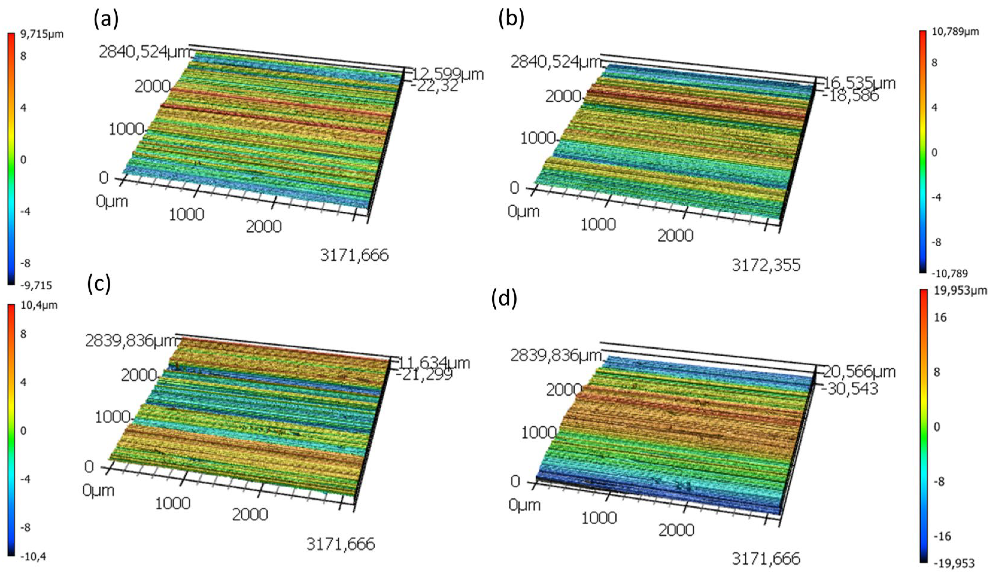
3.2.5. Surface Morphology and Microtopography

In this section, the surface microtopography of the grinding wheel after the grinding operation under parameter set 3 is analyzed in Figure 14. The optical analysis can give insight into the wear mechanisms, wheel loading, and sharpness of the grinding wheel. The surface topography of all GWs with all parameter sets shows partial grain pull-out and a worn bond surface. The contact between the bond and the workpiece can also enhance the forces and the wear. In the case of GW-1, it is seen that the force ratio is higher than the other GWs, but it also has comparatively higher wear. Therefore, it can be concluded that the additives enhance the resistance to wear, but in conversion, higher forces are achieved. It is also seen that the surface of GW-1 contains more dull grains, which could be a sign of the reduced cuttability of this wheel, causing lower surface quality (see Figure 13). Conversely, GW-1 contains more active and sharp grains, indicating a long tool lifespan, as well as higher surface quality and less tool wear. The surface morphology of GW-3 (Figure 14c) illustrates the grain pull-out and signifies a worn surface, which could be attributed to the lower tensile strength of this bond compared to the other grinding wheels. GW-4 represents the morphology surface with a slightly less significant worn bond, which comes from the existence of the higher fraction of copper particles, increasing the hardness of the bond.
A comparison of the surface topography of the workpiece surface after grinding with printed wheels (see Figure 15) corroborates the aforementioned surface roughness results from the preceding section. Furthermore, it is evident that the final ground surfaces produced by GW-1, GW-2, and GW-3 exhibit comparable surface integrity. However, GW-4 exhibits a slight convex pattern on the surface, which is likely attributable to uneven wear on the grinding wheel.

4. Conclusions

This work aimed to investigate the influence of fillers, such as glass fibers, carbon fibers, and copper particles, on the grinding performance of additively manufactured resin-bonded grinding wheels using the DLP process. Since the most applicable resin bond grinding wheels in the industry are produced incorporating phenol-based resin, it was challenging to make this resin UV-curable. Therefore, UV-curable phenol resin was developed by Osnabrück University and utilized for the first time to print grinding wheels. Mechanical tests were conducted on tensile samples to identify a correlation between grinding performance and mechanical properties. The findings indicate that the mechanical properties can be significantly altered by the incorporation of additives, which notably impact the grinding performance. Some of the main achievements are listed below:
  • Adding different additives makes a notable improvement to the mechanical properties, including the tensile strength and E-modulus of the grinding wheel compositions. This was more prominent for glass fiber with a 50% increase in the tensile strength and carbon fiber with a 16% increase in E-modulus compared to the phenol-SiC (TS1) composition;
  • Comparing the grinding forces showed a significant change (up to 25%) between the compositions when the highest depth of cut (100 µm) was applied. The increase in the depth of cut led to notable growth in the force values of up to 50% of all examined grinding wheels. A higher normal force for GW-2 mainly originated from improved grain retention by adding glass fibers;
  • Reinforced grinding wheels with glass fiber represented the highest wear resistance compared to the other examined grinding wheels with up to 75% reduction in tool wear value;
  • For shallow grinding, the results indicate that GW with lower strength produces better surface quality mainly due to the higher tool wear and lower forces. However, with deep grinding, GW-2 represented improved surface quality compared to the other examined grinding wheels;
  • The surface morphology of the grinding wheels following the grinding operation indicates the presence of a worn bond, grain pull-out, and dull grains, with these effects being less significant for the grinding wheel reinforced with glass fiber.

Author Contributions

Conceptualization, M.B.; Methodology, A.H., M.B. and F.S.; validation, M.B. and F.S.; investigation, M.B. and F.S.; data curation, M.B. and F.S.; writing—original draft preparation, M.B. and F.S.; writing—review and editing, M.B. and F.S.; supervision, B.A. All authors have read and agreed to the published version of the manuscript.

Funding

This work was supported by the Zentrales Innovationsprogramm Mittelstand (ZIM) under grant No. KK5080103CD1.

Institutional Review Board Statement

Not applicable.

Informed Consent Statement

Not applicable.

Data Availability Statement

Datasets are available upon request.

Conflicts of Interest

The authors declare no conflicts of interest.

References

  1. Schneider, G. American Machinist (29 June 2020), Cutting Tool Applications, Chapter 16: Grinding Wheels and Operations. Available online: https://www.americanmachinist.com/cutting-tools/media-gallery/21135367/chapter-16-grinding-wheels-and-operations-cutting-tool-applications (accessed on 25 July 2024).
  2. Luo, S. Effect of fillers of resin-bonded composites on diamond retention and wear behavior. Wear 1999, 236, 339–349. [Google Scholar] [CrossRef]
  3. Azarhoushang, B.; Marinescu, I.D.; Rowe, W.B.; Dimitrov, B.; Ohmori, H. (Eds.) Tribology and Fundamentals of Abrasive Machining Processes, 3rd ed.; William Andrew Publishing: Norwich, NY, USA, 2022. [Google Scholar]
  4. Linke, B. Manufacturing and sustainability of bonding systems for grinding tools. Prod. Eng. 2016, 10, 265–276. [Google Scholar] [CrossRef]
  5. Lawson, S.; Li, X.; Thakkar, H.; Rownaghi, A.A.; Rezaei, F. Recent Advances in 3D Printing of Structured Materials for Adsorption and Catalysis Applications. Chem. Rev. 2021, 121, 6246–6291. [Google Scholar] [CrossRef] [PubMed]
  6. Ai, Q.; Khosravi, J.; Azarhoushang, B.; Daneshi, A.; Becker, B. Digital light processing-based additive manufacturing of resin bonded SiC grinding wheels and their grinding performance. Int. J. Adv. Manuf. Technol. 2022, 118, 1641–1657. [Google Scholar] [CrossRef]
  7. Barmouz, M.; Steinhäuser, F.; Azarhoushang, B.; Khosravi, J. Influence of bond thermal and mechanical properties on the additively manufactured grinding wheels performance: Mechanical, wear, surface integrity, and topography analysis. Wear 2024, 538, 205215. [Google Scholar] [CrossRef]
  8. Barmouz, M.; Azarhoushang, B.; Zahedi, A.; Rabiei, F.; Steinhäuser, F. Progress in grinding performance by additive manufacturing of grinding wheels integrated with internal venturi cooling channels and surface slots. J. Manuf. Process. 2023, 99, 485–500. [Google Scholar] [CrossRef]
  9. Barmouz, M.; Steinhäuser, F.; Azarhoushang, B. Tailored bond characteristics in additively manufactured resin bond grinding wheels: Achieving optimal performance, high abrasive concentration, and cost efficiency. Prog. Addit. Manuf. 2024, 24, 1–22. [Google Scholar] [CrossRef]
  10. Whitmore, L. A precision manual grinding tool for sample preparation. Ultramicroscopy 2021, 233, 113436. [Google Scholar] [CrossRef] [PubMed]
  11. Kishore, K.; Sinha, M.K.; Singh, A.; Archana; Gupta, M.K.; Korkmaz, M.E. A comprehensive review on the grinding process: Advancements, applications and challenges. Proc. Inst. Mech. Eng. Part C J. Mech. Eng. Sci. 2022, 236, 10923–10952. [Google Scholar] [CrossRef]
  12. Yang, Z.; Zhang, M.; Zhang, Z.; Liu, A.; Yang, R.; Liu, S. A study on diamond grinding wheels with regular grain distribution using additive manufacturing (AM) technology. Mater. Des. 2016, 104, 292–297. [Google Scholar] [CrossRef]
  13. Tian, C.; Li, X.; Zhang, S.; Guo, G.; Wang, L.; Rong, Y. Study on design and performance of metal-bonded diamond grinding wheels fabricated by selective laser melting (SLM). Mater. Des. 2018, 156, 52–61. [Google Scholar] [CrossRef]
  14. Denkena, B.; Krödel, A.; Harmes, J.; Kempf, F.; Griemsmann, T.; Hoff, C.; Hermsdorf, J.; Kaierle, S. Additive manufacturing of metal-bonded grinding tools. Int. J. Adv. Manuf. Technol. 2020, 107, 2387–2395. [Google Scholar] [CrossRef]
  15. Qiu, Y.; Huang, H.; Xu, X. Effect of additive particles on the performance of ultraviolet-cured resin-bond grinding wheels fabricated using additive manufacturing technology. Int. J. Adv. Manuf. Technol. 2018, 97, 3873–3882. [Google Scholar] [CrossRef]
  16. Klocke, F. Fertigungsverfahren 2; Springer: Berlin/Heidelberg, Germany, 2018. [Google Scholar]
  17. Francois, E.C.; Zhang, G.; Klett, M.W. Saint Gobain Abrasives INC°[US]; Saint Gobain Abrasifs SA°[FR]. WO2010078191 (A2), 2009.
  18. Fu, S.-Y.; Feng, X.-Q.; Lauke, B.; Mai, Y.-W. Effects of particle size, particle/matrix interface adhesion and particle loading on mechanical properties of particulate–polymer composites. Compos. Part B Eng. 2008, 39, 933–961. [Google Scholar] [CrossRef]
  19. Goh, G.D.; Dikshit, V.; Nagalingam, A.P.; Goh, G.L.; Agarwala, S.; Sing, S.L.; Wei, J.; Yeong, W.Y. Characterization of mechanical properties and fracture mode of additively manufactured carbon fiber and glass fiber reinforced thermoplastics. Mater. Des. 2018, 137, 79–89. [Google Scholar] [CrossRef]
  20. Amoabeng, D.; Velankar, S.S. Bulk soldering: Conductive polymer composites filled with copper particles and solder. Colloids Surf. A Physicochem. Eng. Asp. 2018, 553, 624–632. [Google Scholar] [CrossRef]
  21. Joseph, S. A comparison of the mechanical properties of phenol formaldehyde composites reinforced with banana fibres and glass fibres. Compos. Sci. Technol. 2002, 62, 1857–1868. [Google Scholar] [CrossRef]
Figure 1. Images of the different additives.
Applsci 14 07711 g001
Figure 2. Different steps of grinding wheel production using DLP.
Applsci 14 07711 g002
Figure 3. Optical images of the printed grinding wheels (a) GW-1, (b) GW-2, (c) GW-3, and (d) GW-4.
Applsci 14 07711 g003
Figure 4. Experimental setup for grinding operation.
Applsci 14 07711 g004
Figure 5. Influence of the additives on the tensile strength.
Applsci 14 07711 g005
Figure 6. Influence of the additives on the E-modulus.
Applsci 14 07711 g006
Figure 7. Microtopography of (a) GW-1, (b) GW-2, (c) GW-3, and (d) GW-4 after dressing.
Applsci 14 07711 g007
Figure 8. Grinding forces of the grinding experiment with parameter set 1.
Applsci 14 07711 g008
Figure 9. Grinding forces of the grinding experiment with parameter set 2.
Applsci 14 07711 g009
Figure 10. Grinding forces of the grinding experiment with parameter set 3.
Applsci 14 07711 g010
Figure 11. Grinding forces (a) normal force (Fn) and (b) tangential force (Ft) for different printed grinding wheels under different grinding parameters.
Applsci 14 07711 g011
Figure 12. Results of (a) tool wear and (b) real depth of cut for all GWs.
Applsci 14 07711 g012
Figure 13. Surface roughness measurements (a) Ra and (b) Rz for all the GWs.
Applsci 14 07711 g013
Figure 14. Surface morphology of the printed grinding wheels (a) GW-1, (b) GW-2, (c) GW-3, and (d) GW-4 after grinding operation with parameter set 3.
Applsci 14 07711 g014
Figure 15. Surface topography of the ground surface of (a) GW-1, (b) GW-2, (c) GW-3, and (d) GW-4 with parameter set 3.
Applsci 14 07711 g015
Table 1. Materials.
Table 1. Materials.
MaterialParticle Size [μm]Fiber Length [mm]Fiber Diameter [nm]
Silicon carbide (SiC)60–70__
Glass fiber (GF)_12100
Carbon fiber (CF)_3100
Copper (Cu)40__
Table 2. Grinding wheel specifications.
Additive-Manufactured Grinding Wheels
Grinding Wheel No.Equal as Tensile SamplePhenol Resin w%Abrasives w% Additives w%
GW-1TS-158.8%SiC 41.2%_
GW-2TS-258.1%SiC 40.7%GF 1.2%
GW-3TS-358.5%SiC 40.9%CF 0.6%
GW-4TS-455.6%SiC 38.9%Cu 5.5%
Table 3. Tensile sample specifications.
Tensile Samples
Sample No.Phenol Resin w%Abrasives w% Additives w%
TS-0100%__
TS-158.8%SiC 41.2%_
TS-258.1%SiC 40.7%GF 1.2%
TS-358.5%SiC 40.9%CF 0.6%
TS-455.6%SiC 38.9Cu 5.5%
Table 4. Grinding parameters for Al.
Parameter Set 1
Grinding wheelGW-1; GW-2; GW-3; GW-4;Workpiece materialAluminium 7075
Grinding parametersVS = 30 m/s, Vft = 6000 mm/min, ae = 10 µm
Dressing and sharpening parameterDressing: aed = 4 µm, Vsd = 10 m/s, Ud = 9CoolantEmulsion
Parameter Set 2
Grinding wheelGW-1; GW-2; GW-3; GW-4;Workpiece materialAluminium 7075
Grinding parametersVS = 30 m/s, Vft = 1200 mm/min, ae = 50 µm
Dressing and sharpening parameterDressing: aed = 4 µm, Vsd = 10 m/s, Ud = 9CoolantEmulsion
Parameter Set 3
Grinding wheelGW-1; GW-2; GW-3; GW-4;Workpiece materialAluminium 7075
Grinding parametersVS = 30 m/s, Vft = 600 mm/min, ae = 100 µm
Dressing and sharpening parameterDressing: aed = 4 µm, Vsd = 10 m/s, Ud = 9CoolantEmulsion
Disclaimer/Publisher’s Note: The statements, opinions and data contained in all publications are solely those of the individual author(s) and contributor(s) and not of MDPI and/or the editor(s). MDPI and/or the editor(s) disclaim responsibility for any injury to people or property resulting from any ideas, methods, instructions or products referred to in the content.

