Article

The Influence of Gas-Dynamic Non-Stationarity of Air Flow on the Heat Transfer Coefficient in Round and Triangular Straight Pipes with Different Turbulence Intensities

Turbines and Engines Department, Ural Federal University Named after the First President of Russia B.N. Yeltsin, Str. Mira, 19, Yekaterinburg 620062, Russia
*
Author to whom correspondence should be addressed.
Appl. Sci. 2024, 14(17), 7758; https://doi.org/10.3390/app14177758
Submission received: 11 August 2024 / Revised: 28 August 2024 / Accepted: 30 August 2024 / Published: 2 September 2024
(This article belongs to the Special Issue Fluid Flow and Heat Transfer: Latest Advances and Prospects)

Abstract

:
Unsteady gas-dynamic phenomena in pipelines of complex configuration are widespread in heat exchange and power equipment. Therefore, studying the heat transfer level of pulsating air flows in round and triangular pipes with different turbulence intensities is a relevant and significant task for the development of science and technology. The studies were conducted on a laboratory stand based on the thermal anemometry method and an automated system for collecting and processing experimental data. Rectilinear round and triangular pipes with identical cross-sectional areas were used in the work. Flow pulsations from 3 to 15.8 Hz were generated by means of a rotating flap. The turbulence intensity (TI) of the pulsating flows varied from 0.03 to 0.15 by installing stationary flat turbulators. The working medium was air with a temperature of 22 ± 1 °C moving at a speed from 5 to 75 m/s. It was established that the presence of gas-dynamic unsteadiness leads to an increase in the TI by 47–72% in a round pipe and by 36–86% in a triangular pipe. The presence of gas-dynamic unsteadiness causes a heat transfer intensification in a round pipe by 26–35.5% and by 24–36% in a triangular pipe. It was shown that a significant increase in the TI of pulsating flows leads to an increase in the heat transfer coefficient by 11–16% in a round pipe and a decrease in the heat transfer coefficient by 7–24% in a triangular pipe. The obtained results can be used in the design of heat exchangers and gas exchange systems in power machines, as well as in the creation of devices and apparatuses of pulse action.

1. Introduction

Working media in the form of pulsating flows of liquid and gas in pipes of various configurations are used in many branches of industry and technology (for example, pulsating heat pipes [1], solar energy [2] and piston engines [3]). In most cases, the efficiency of the final product (engine, heat exchanger, power plant, etc.) depends on the gas-dynamic and heat-exchange perfection of the working fluid processes in systems with pipes of various configurations. In such systems, the thermogasdynamics of the flow are determined by a large number of factors: (1) the characteristics of the flow pulsations (frequency, amplitude, type); (2) the flow turbulence intensity, and (3) the geometric configuration of the pipeline. Therefore, obtaining data on gas dynamics and heat exchange of pulsating gas flows in straight pipes with different cross-section shapes for different turbulence conditions remains a relevant and important task for the development of fundamental and applied science, as well as for increasing the efficiency of energy technologies. A brief overview of modern research results on this topic is presented below.
The impact of gas-dynamic non-stationarity (pulsations) of gas flow on the intensity of heat transfer in pipeline systems remains the focus of attention of many researchers [4,5,6,7,8]. Nishandar and colleagues conducted a detailed study of the gas-dynamic features of pulsating flows in a pipe to clarify the physical mechanism of changes in the heat transfer level [4]. The authors identified several important factors that had a decisive influence on heat exchange: the Reynolds number, the length and diameter of the pipe, and the frequency and amplitude of the flow pulsation. It was found that high-frequency flow velocity pulsations increase the local Nusselt number in the pipe. Hayrullin et al. studied the effect of flow pulsations on the heat exchange level in a tube bundle of heat exchangers of various designs [5,6]. It was established that, in this case, the intensification of heat exchange increases with the growth of the amplitude and frequency of flow pulsations and decreases with the growth of the Reynolds number. An increase in the heat transfer coefficient (HTC) by 1.25–1.6 times compared to a steady flow was recorded. Van Buren et al. studied pulsating flows in a pipe with flow reversal [7]. It was shown that there was an increase in the HTC of up to 60% at the moments of flow reversal compared to the steady-state movement of the medium. At the same time, the increase in the average HTC for the full cycle of the pulsation under consideration was insignificant. Nakamura and colleagues separately investigated the effect of air flow acceleration and deceleration on the heat transfer rate in a pipe [9].
There are also applied studies on the influence of gas flow pulsations on the heat exchange level in the exhaust systems of piston engines [10,11]. For example, Simonetti et al. studied the heat transfer of engine exhaust gases pulsating with frequencies from 10 to 95 Hz [10]. The authors found that flow pulsations improved heat transfer in the system across the entire frequency range. The key factor in increasing the HTC was the relative amplitude of the gas flow velocity. In turn, Kato and colleagues found that the increased intensity of heat transfer of exhaust gases at frequencies of 25–35 Hz could be associated with increased flow turbulence caused by flow pulsations in the exhaust system [11].
A separate area of research into pulsating flows in various gas-dynamic systems consists of studying the effect of flow turbulence on the heat exchange intensity [12,13,14,15,16]. One of the most well-known and effective methods for improving heat exchange of air flow in channels is the creation of various types of dimples and/or grooves on the inner surface (spherical dimples, flat rectangle, square groove, rectangular groove, etc.). For example, this can cause flow turbulence and a corresponding intensification of heat transfer by up to two times compared to smooth surfaces [12,13]. De Maio and colleagues found that a significant increase in pipe roughness also caused a rise in the flow turbulence intensity (TI) and an intensification of heat transfer by 4–13% compared to a smooth pipe [14]. There are also other ways to turbulize the flow of liquid and gas in order to intensify heat exchange, for example, by installing an aerodynamic spoiler or creating special fins on the channel surface [15,16]. This can lead to an increase in the HTC by 170% compared to a smooth surface.
It is also known that the cross-sectional shape of a pipeline can have a significant impact on the gas-dynamic conditions of heat exchange of stationary and pulsating gas flows [17,18,19,20]. Thus, Nikitin and colleagues studied in detail the formation and development of secondary flows in a pulsating flow in the corners of a square pipe [17,18]. The authors described the physical mechanism of eddy currents in the corners of a square and proposed a mathematical model for their prediction. Kumar et al. reviewed the studies on the features of gas dynamics and heat transfer in triangular tubes [19]. It was shown that strong secondary flows were also formed in triangular tubes. These secondary flows significantly transformed the gas-dynamic characteristics and also caused a modification of the heat exchange level in the gas-dynamic system under consideration.
Many researchers have paid attention to the comparison of the heat transfer intensity of stationary and pulsating flows in square and triangular channels [19,21,22,23]. Thus, Guo et al. found that there was a slight decrease in the HTC in a square with a pulsating movement of the medium compared to a stationary flow [21]. Similar data were obtained by Nikitin: gas-dynamic non-stationarity in a square pipe caused suppression of the HTC by up to 15% [22]. Pirozzoli et al. compared the level of heat exchange of stationary flows in round and square pipes [23]. It was shown that changing the shape of the cross section has a weak effect on the heat transfer intensity. At the same time, Kumar and colleagues found a slight intensification of heat exchange in a triangular pipe (TrP) compared to a round one [19]. Accordingly, it can be concluded that the gas dynamics and heat exchange of flows in pipes with different cross-sectional shapes have not been studied in sufficient detail: different configuration and regime conditions in the formulation of the research problem lead to the opposite effects.
There have also been developments and studies on the use of specific tube designs for heat exchange intensification [24,25,26]. For example, Zhang and colleagues investigated the features of gas dynamics and heat exchange in wave and arc tubes [24]. The results showed a noticeable intensification of heat exchange in almost all studied modes (for all Reynolds numbers). Kurtulmuş and Sahin obtained similar results for a sinusoidal tube [25]. It should be noted that the studies were conducted for stationary and pulsating flows. In this case, gas-dynamic non-stationarity led to an additional increase in the HTC. Ishaq et al. used diamond-shaped tubes in a heat exchanger to improve heat transfer [26].
Accordingly, the study of the influence of configurational (various cross-sectional shapes of channels) and regime (stationary and pulsating flows) factors on the gas dynamics and heat exchange of flows in pipelines remains a popular and important task in the development of science and technology (for example, heat pipes [27], power machines [28], thermoelectric generators for exhaust gases [29], etc.).
Thus, the main objectives of this study were as follows:
-
To obtain experimental data on instantaneous values of velocity and local HTC of stationary and pulsating air flows with different levels of turbulence in straight pipes with different cross-sectional shapes;
-
To evaluate the effect of gas-dynamic non-stationarity on the air flow turbulence intensity in round and triangular straight pipes;
-
To establish the effect of gas-dynamic non-stationarity on the air flow heat transfer intensity in round and triangular pipes;
-
To identify the effect of air flow pulsation frequency on the TI and the HTC of air flows in pipes with different cross-sectional shapes.
The scientific significance of the study was that information about the impact of gas-dynamic non-stationarity (pulsation frequency) on the TI and the heat exchange level of the air flow in a triangular rectilinear pipe was obtained, and a comparative analysis of the impact of the initial TI on gas dynamics and heat exchange in the system under consideration was carried out.
The practical significance of the research lies in obtaining thermophysical patterns for the design of advanced heat exchangers and original gas exchange systems in power machines, as well as for the creation of pulsed (periodic) devices.
The advantage of this study is that it is based on proven experimental methods, contains reliable data on gas dynamics and heat exchange of air flows, and presents significant, original scientific results.
The article has a traditional structure: (1) an introduction with a description of the current state of research in this area, as well as with formulations of the objectives of the work and its scientific and practical significance; (2) a description of the research methods, measuring equipment, and the main boundary conditions of the experiments; (3) experimental data on gas dynamics and heat exchange of air flows in pipelines and their analysis; (4) the main conclusions of the study with a formulation of directions for further research on this topic; (5) references.

2. Description of the Research Task and Measuring Instruments

The study of non-stationary gas dynamics and heat exchange of flows in straight pipes was carried out by means of experimental approaches based on the thermal anemometry method. A laboratory setup was developed for these purposes, the scheme of which was shown in Figure 1.
The laboratory setup consists of the following main elements: (1) a vacuum pump to create air movement in the gas-dynamic system; (2) straight pipelines with circular and triangular cross-sections; (3) static flat air flow turbulators; (4) a rotating damper to create air flow pulsations; (5) an automated measuring system based on a constant-temperature hot-wire anemometer (H-WA). A photograph of the experimental setup is shown in Figure 2 (the measurement system is described below).
The flow pulsations in the gas-dynamic system were created by means of a damper (Figure 3a), the rotation frequency of which could be changed by means of a voltage regulator. In this way, air flow pulsations with a frequency f from 3 to 16.6 Hz were generated. Such pulsating flows are typical for various periodic devices (for example, piston machines) and for pulse devices of various purposes.
Stationary flat turbulators were used to change the turbulence intensity TI of stationary and pulsating flows in straight pipes (Figure 3b). Several turbulators with different numbers of holes and different hole diameters were used. Thus, the flow TI varied from 0.03–0.04 (flow without a turbulator) to 0.12 (maximum average TI value).
Two straight pipeline configurations were used in the study. The base pipe had a circular cross-section with an internal diameter of 30 mm. The alternative pipe had a cross-section in the form of an equilateral triangle with a side length of 39 mm. The geometry of the TrP was chosen based on the equality of the cross-sectional area of both pipes. The length of the pipelines was 1 m in both cases. The scientific idea of studying a TrP is based on known data that strong secondary flows are formed in channels with transverse profiling, which significantly affect the gas-dynamic and heat exchange characteristics of the flows [30,31]. The pipelines were made of a metal alloy. The inner surfaces of the pipes had a technically smooth surface (the roughness of the surface did not affect the intensity of heat exchange between the air flow and the wall).
The working medium in the experiments was air with a temperature of 22 ± 1 °C moving at a speed of 5 m/s to 75 m/s (10,000 < Re < 150,000), i.e., the flow regime was developed turbulent. The experiments were carried out at an atmospheric pressure of 98.0 ± 0.2 kPa.
The following parameters were measured in the experiments: (1) instantaneous values of the air flow velocity wx (using a H-WA with a response time of no more than 3 ms); (2) instantaneous values of the local HTC αx (using a H-WA with an identical response time); (3) flow temperature (using thermocouples); (4) damper rotation frequency (using an inductive sensor); (5) atmospheric pressure (using a manometer).
The thermal anemometry method was the main research method in this work. Special sensors with a thread sensitive element were manufactured for a H-WA to measure wx and αx [32,33]. The thread had a diameter of 5 µm and a length of about 5 mm. The thread was placed on posts approximately in the center of the pipe to determine wx. The thread was mounted on a substrate and was flush with the inner surface of the pipe to determine αx. A constant temperature H-WA from Irvis (Moscow, Russia) was used; the sensors were manufactured independently. More detailed information about the sensors and the method of their installation in pipelines of different configurations can be found in the article [34]. This article presents data obtained with the help of sensors located at a distance of 150 mm from the turbulator (see also Figure 1).
Signals from all sensors were fed to the LCard (Moscow, Russia) analog-to-digital converter (ADC) in real time, after which the digitized signals were transferred to specialized LGraph2 (version 3.25.20) software (Russia) for storage and processing. The response time of the measuring system based on a H-WA and ADC was from 3 to 6 ms. This response time is sufficient for studying pulsating flows with a frequency of up to 100 Hz.
The relative uncertainty in determining wx was 5.3%; the relative uncertainty in determining αx was 10.9%; the relative uncertainty in measuring the flow temperature was 1.0%. The following errors of measuring instruments were taken into account to determine the relative uncertainty of the experiment: barometric pressure (barometer, 0.1%), pressure drop in the flow (micromanometer, 2.2%), air temperature (thermocouple, 1.0%), linear dimensions of the pipe (caliper, 0.6%), and the thermophysical properties of substances (handbook, 2.0%). The relative uncertainty was also calculated considering the conversion of analog signals from sensors into digital data (1.1%).
Thus, a gas-dynamic system with an automated measuring base was developed, which made it possible to study the gas dynamics and heat exchange of stationary and pulsating air flows with different pulsation frequencies and different turbulence intensities. The experimental stand has the possibility of modernization for the study of other system configurations and initial conditions of tests.

3. Experimental Research Results, Analysis and Discussion

Primary data on the change in instantaneous values of velocity wx and local HTC αx over time during the movement of a pulsating air flow in round and triangular pipes without a turbulator are shown in Figure 4 and Figure 5.
The following conclusions were drawn based on a comparison of the data in Figure 4 and Figure 5:
-
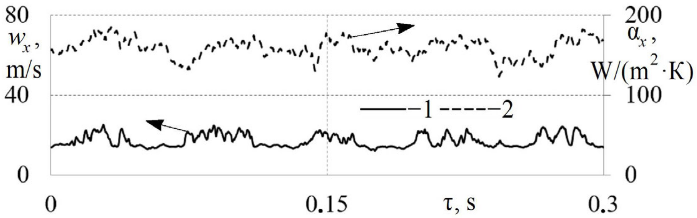
There are pronounced flow pulsations (with corresponding maxima and minima of wx and αx), caused by the blocking of the pipe by the valve for both cases;
-
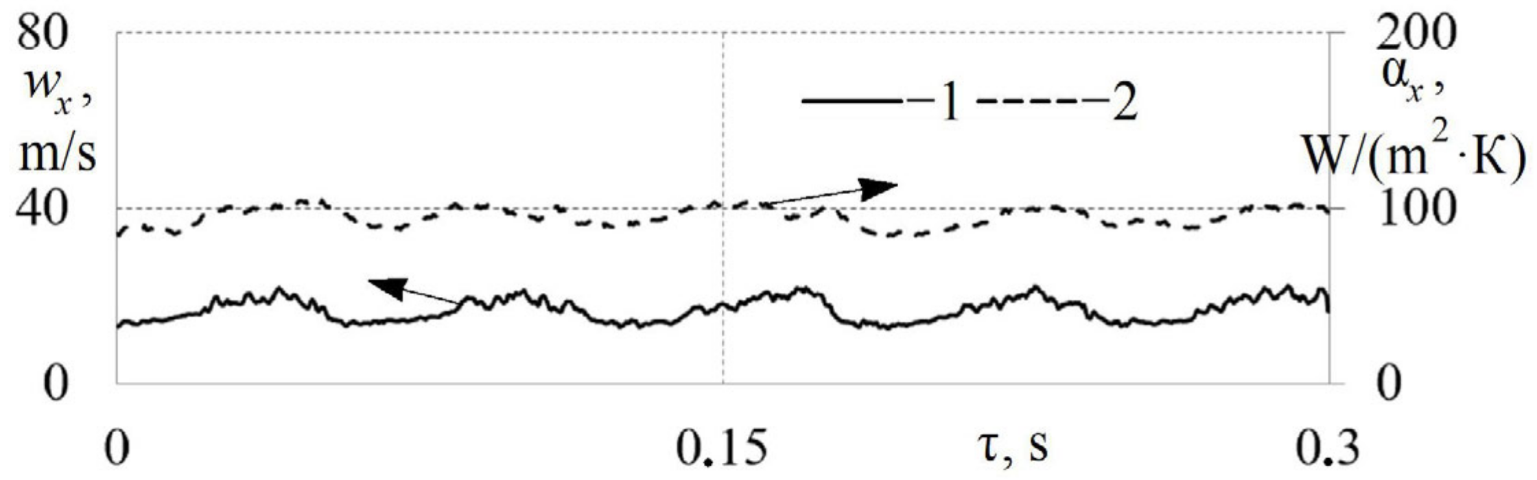
The dependencies wx = f (τ) and αx = f (τ) are practically smooth (with minimal fluctuations) when the flow moves in a round pipe, whereas noticeable fluctuations in the velocity wx and the local HTC αx of the flow are observed when using a TrP; their formation can be associated with secondary vortex flows in the corners of the triangular profile;
-
The maximum values of αx in a TrP are visually 10–15% less compared to a round pipe under these experimental conditions.
Primary data on the change in instantaneous values of the velocity wx and local HTC αx over time during the movement of a pulsating air flow in a round and TrP with a turbulator are shown in Figure 6 and Figure 7.
It can be seen from Figure 6 that an increase in the flow TI caused a significant deformation of the dependencies wx = f (τ) and αx = f (τ) in the round tube. The amplitude of the air flow oscillation is comparable with the amplitude of the main pulsations. It is visually difficult to identify pulsations of the local HTC caused by a rotating damper on the function αx = f (τ).
The pulsating air flow in a TrP is more resistant to an increase in TI (Figure 7). Fluctuations in the local flow velocity wx have a significantly smaller amplitude in a TrP compared to a round one. The function αx = f (τ) is more pronounced (clear); it is possible to easily identify the pulsations of the local HTC due to the damper rotation in the pipeline. Accordingly, it can be assumed that the secondary vortex structures in the TrP impart rigidity to the flow and prevent its deformation under the influence of external disturbances.
The TI for round and triangular pipes in free flow (i.e., without using a turbulator) was calculated to quantitatively assess the magnitude of the pulsation component of the air flow velocity in the gas-dynamic system (Figure 8 and Figure 9). Analysis of Figure 8 and Figure 9 shows the influence of gas-dynamic non-stationarity and geometric shape of pipelines on the turbulence intensity in straight pipes. TI was defined as the ratio of the mean square pulsating component of velocity to the average velocity of the flow under study; the method for calculating TI for pulsating flows was described in detail in the article [35].
Figure 8 shows that there is a tendency for TI values to increase with a rise in the average air flow velocity in a circular pipe, which is typical for stationary and pulsating flows. At the same time, gas-dynamic non-stationarity (flow pulsations) causes a significant increase in the TI by almost double compared to stationary flow. These differences are typical for all the air flow velocities under study. At the same time, an increase in the pulsation frequency f actually does not affect TI (the differences are within the limits of experimental uncertainty).
Other patterns of change in the flow TI occur in a triangular pipe (Figure 9). TI values grow with increasing flow velocity for stationary air flow in a TrP (Figure 9). However, the opposite trend is observed for pulsating flows: the TI values decrease with increasing velocity in a TrP. At the same time, the TI values are 1.36–2.2 times higher for pulsating flows compared to steady air movement at velocities w < 40 m/s. The TI values are approximately the same (within the experimental uncertainty) for steady and pulsating flows for w > 40 m/s. The flow pulsation frequency f also has little effect on turbulence intensity. The observed features of TI change in a triangular pipe can be explained by longitudinal vortex structures formed in the channel corners. They probably stabilize the flow and prevent gas-dynamic deformation under the influence of external factors.
Accordingly, a TrP should be used to suppress turbulence (alignment) of the flow in technical devices of cyclic action. The stabilization effect is clearly expressed for velocities w > 50 m/s.
Juxtaposition of Figure 8 and Figure 9 shows that:
-
There is a significant influence of gas-dynamic non-stationarity on the flow structure and pulsating components of the air flow velocity in a TrP;
-
There are opposite tendencies in the change of TI in stationary and pulsating flows in a TrP;
-
It is necessary to use optical methods or an entropy generation method [36] for a detailed study of the gas dynamics of pulsating flows (the thermal anemometry method does not provide a complete physical picture of the processes taking place).
A significant change in the gas-dynamic conditions in the triangular tube should lead to a modification of the heat exchange characteristics of stationary and pulsating air flows. Therefore, the average HTC α was additionally calculated in both tubes for different boundary conditions. The coefficient α was defined as the mathematical expectation of the function αx = f (τ) for one pulsation period.
The influence of gas-dynamic non-stationarity of the flow and the shape of the pipeline cross-section on the heat transfer level in straight pipes can be traced based on Figure 10 and Figure 11.
It can be seen from Figure 10 that gas-dynamic non-stationarity causes an intensification of heat transfer in a round straight pipe by 22–30%. At the same time, a rise in the flow pulsation frequency f does not cause a noticeable further increase in the HTC (the increase in α is 4–5.5% with an increase in f from 4.6 Hz to 15.3 Hz, which is within the uncertainty limits of the experiment). Similar data on the influence of air flow pulsations on the level of heat exchange in various gas-dynamic systems can be found in the work of other authors [37,38]. There is a similarity of scientific results that gas-dynamic non-stationarity causes an intensification of heat exchange within 20–40%. There are also data from other authors that suggest an increase in the TI values causes a rise in the HTC [39]. The detected intensification of heat exchange in pulsating flows may be associated with large- and small-scale oscillations in the flow, and the corresponding restructuring and weakening of the boundary layer, which contributes to improved heat transfer.
Gas-dynamic non-stationarity has a similar effect on the heat exchange level of flows in a TrP: there is an intensification of the HTC α by 24–36% compared to a steady flow (Figure 11). Also, an increase in the pulsation frequency from 3 Hz to 15.8 Hz does not actually affect the heat transfer intensity (an insignificant decrease in α by 2–11% is observed, which is within the uncertainty limits of the experiment). Accordingly, it can be stated that gas-dynamic non-stationarity has a similar effect on the heat exchange level of the air flow in round and triangular pipes.
Accordingly, the creation of flow pulsations in a gas-dynamic system can be considered an effective way to intensify heat exchange. This can be applied in the field of heat exchangers, heat pumps, and engines.
It should be noted that the HTC values of pulsating flows in a TrP are 6.5–13.5% lower than those in a round pipe. This can be explained by the previously discovered effect of stabilizing the pulsating flow in a TrP and lower TI values. Suppression of heat transfer in a TrP has practical application in cases where it is necessary to impair heat exchange between the gas flow and the wall.
The influence of turbulence of a pulsating flow on the heat transfer intensity in pipes with different cross-sectional shapes can be assessed based on Figure 12 and Figure 13. These figures also show the dependence α = f (w) for steady flows without a turbulizer as a baseline for comparison.
Juxtaposition of the dependencies in Figure 10 (data without a turbulator) and Figure 12 (data with flow turbulence) shows that:
-
A rise in TI from 0.04 to 0.08 leads to an increase in the HTC α of pulsating flows in a round pipe by 11–16%, which is in good agreement with [39];
-
A further rise in the TI of the pulsating flow causes an additional small increase in α within 5–8%;
-
Accordingly, there is reason to state that turbulization of the pulsating flow in a round pipe intensifies heat transfer;
-
The pulsation frequency f has a weak effect on the heat transfer level of pulsating flows in a round pipe.
Comparison of the patterns in Figure 11 (data without flow turbulence) and Figure 13 (data with a turbulence generator in the pipe) shows that:
-
An increase in the TI of the pulsating flow (from 0.04 to 0.08) in a TrP leads to a suppression of heat transfer by up to 24%;
-
An increase in the TI of the pulsating flow from 0.04 to 0.15 in a TrP causes a decrease in the HTC to 10.6% (which is within the uncertainty limits of the experiment);
-
Accordingly, it can be concluded that turbulization of the pulsating flow in a TrP suppresses heat transfer; the discovered effect requires additional research to clarify the physical mechanism.
The obtained results indicate that the heat transfer intensity of air flows in pipes with different cross-sections has noticeable differences. This must be taken into account when designing gas-dynamic systems for heat exchange equipment, heat engines, and power plants.
Thus, experimental data on the influence of the geometry of a straight pipe, pulsations, and turbulence of the air flow on the heat transfer intensity were obtained. The obtained data expand the knowledge base of the gas dynamics and heat exchange of stationary and pulsating flows in pipelines for different initial conditions. The discovered scientific results can find application in the design of heat exchangers and gas exchange systems in power engineering, as well as in the creation of machines and devices of cyclic (pulse) action.

4. Conclusions

The following main conclusions can be drawn, based on the analysis and generalization of the obtained data:
  • A laboratory stand and a measuring system with the required speed for studying the gas dynamics and heat exchange of stationary and pulsating flows in straight pipes with different cross-sectional shapes were created;
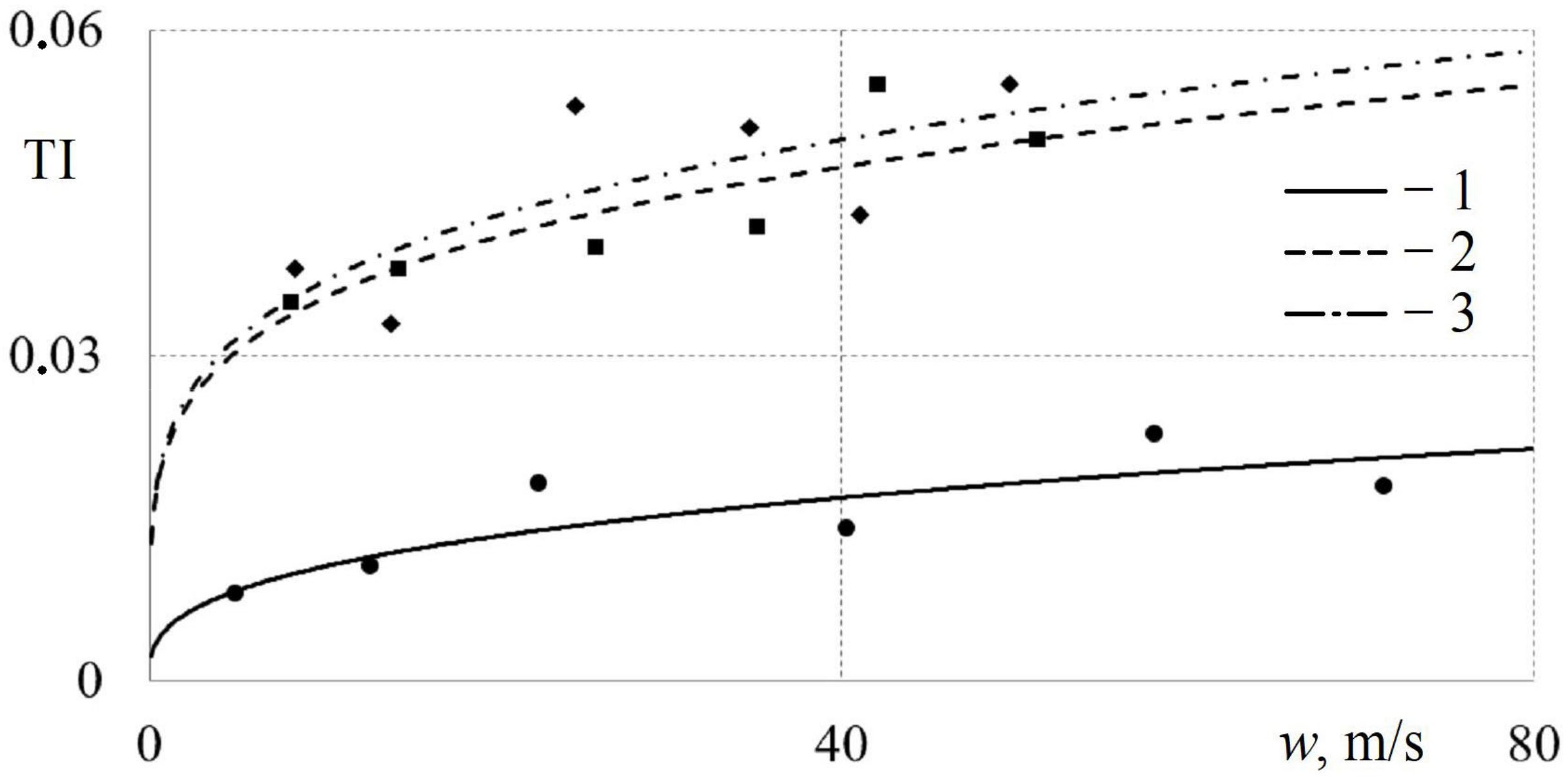
  • It was found that gas-dynamic non-stationarity (the presence of flow pulsations in comparison with steady motion) led to an increase in the TI by 47–72% in a round straight pipe and by 36–86% in a triangular pipe;
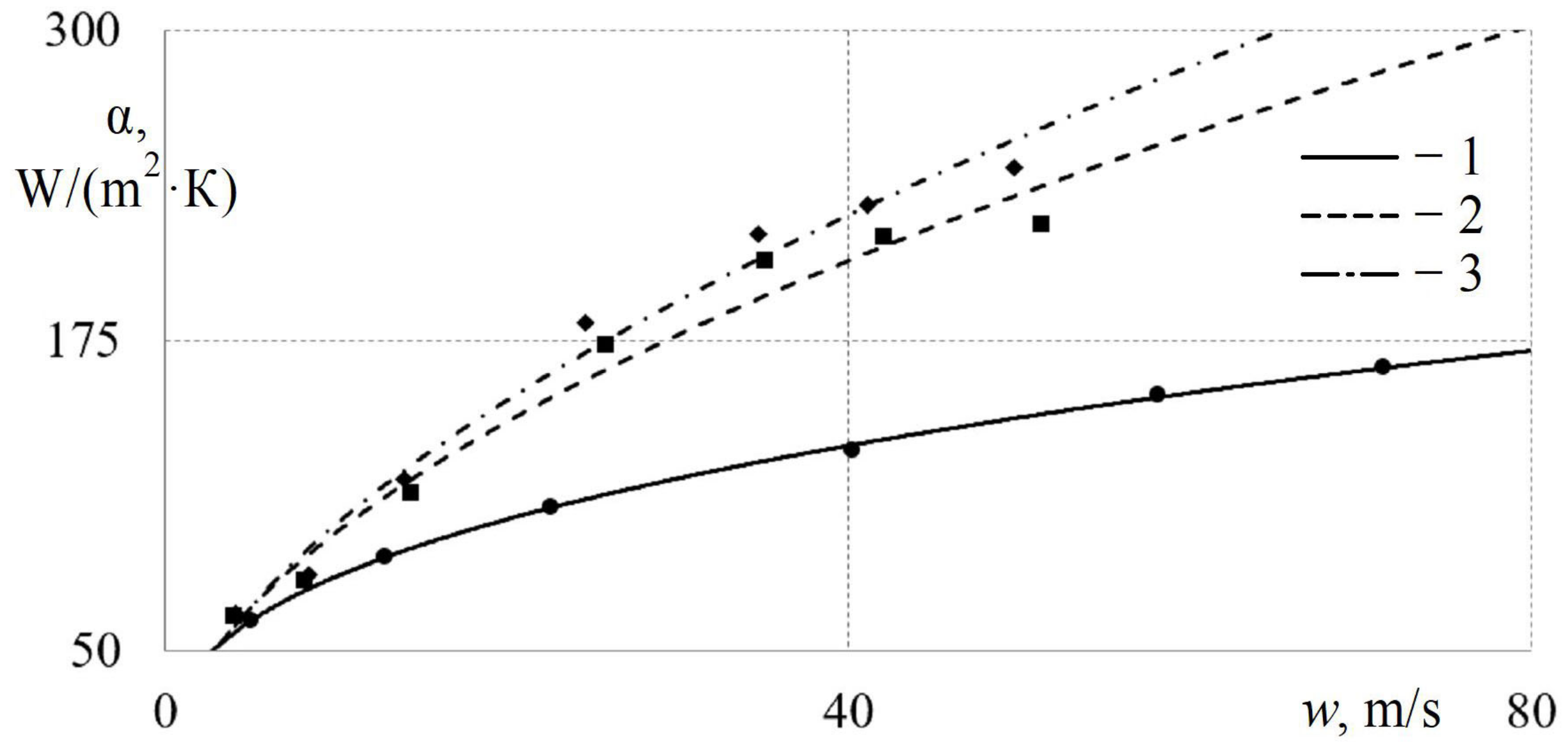
  • It was revealed that gas-dynamic non-stationarity (flow pulsations in the range from 4.6 to 15.3 Hz) caused an intensification of heat transfer in a round straight pipe by 26–35.5%;
  • It was shown that gas-dynamic non-stationarity (flow pulsations in the range from 3.0 to 15.8 Hz) led to an increase in the HTC in a triangular pipe by 24–36%;
  • It was found that increasing TI from 0.04 to 0.12 led to a rise in the HTC of pulsating flows in a round pipe by 11–16%;
  • It was revealed that increasing TI (from 0.04 to 0.15) for a pulsating flow in a triangular pipe caused a suppression of heat transfer by 7–24%;
  • The obtained results confirm the significant influence of flow pulsations, TI, and the cross-sectional shape of pipelines on the gas-dynamic and heat-exchange characteristics of gas flows in straight pipes.
The obtained results can be useful for designing power and heat exchange equipment, and for refining mathematical models for predicting the gas dynamics and heat exchange of stationary and pulsating gas flows.
Obtaining detailed information about the structure of secondary flows in the corners of square and TrPs under conditions of gas-dynamic unsteadiness should be considered a direction for further research on this topic. These studies will improve the understanding of the physical mechanism of transformation of the heat transfer level of pulsating flows in pipelines of different designs. The use of modern optical methods (for example, the PIV method) will be required to solve this pressing problem.

Author Contributions

Conceptualization, L.P.; methodology, L.P. and L.O.; validation, L.P. and L.O.; formal analysis, L.P. and L.O.; investigation, L.P.; resources, L.P.; data curation, L.P.; writing—original draft preparation, L.P. and L.O.; writing—review and editing, L.P.; visualization, L.P. and L.O.; supervision, L.P.; project administration, L.P. All authors have read and agreed to the published version of the manuscript.

Funding

The research funding from the Ministry of Science and Higher Education of the Russian Federation (Ural Federal University Program of Development within the Priority-2030 Program) is gratefully acknowledged.

Institutional Review Board Statement

Not applicable.

Informed Consent Statement

Not applicable.

Data Availability Statement

Data is contained within the article.

Acknowledgments

The authors would like to thank the Ministry of Science and Higher Education of the Russian Federation (Ural Federal University Program of Development within the Priority-2030 Program) for supporting this work.

Conflicts of Interest

The authors declare no conflicts of interest.

References

  1. Yang, K.-S.; Jiang, M.-Y.; Tseng, C.-Y.; Wu, S.-K.; Shyu, J.-C. Experimental investigation on the thermal performance of pulsating heat pipe heat exchangers. Energies 2020, 13, 269. [Google Scholar] [CrossRef]
  2. Matouq, J.; Al-Waked, R.; Al-Rashdan, M.; Mustafa, D.B.; Nasif, M.S. Computational Fluid Dynamics Analysis of Slip Flow and Heat Transfer at the Entrance Region of a Circular Pipe. Appl. Sci. 2024, 14, 6528. [Google Scholar] [CrossRef]
  3. Winkler, N. Effect of pressure oscillations on in-cylinder heat transfer—Through large eddy simulation. Int. J. Engine Res. 2015, 16, 705–715. [Google Scholar] [CrossRef]
  4. Nishandar, S.V.; Pise, A.T.; Bagade, P.M.; Gaikwad, M.U.; Singh, A. Computational modelling and analysis of heat transfer enhancement in straight circular pipe with pulsating flow. Int. J. Interact. Des. Manuf. 2024. [Google Scholar] [CrossRef]
  5. Hayrullin, A.; Haibullina, A.; Sinyavin, A.; Ilyin, V. Experimental study of the in-line tube bundle thermal performance in pulsating flow. Int. J. Heat Mass Transf. 2024, 232, 125916. [Google Scholar] [CrossRef]
  6. Haibullina, A.; Khairullin, A.; Balzamov, D.; Ilyin, V.; Bronskaya, V.; Khairullina, L. Local Heat Transfer Dynamics in the In-Line Tube Bundle under Asymmetrical Pulsating Flow. Energies 2022, 15, 5571. [Google Scholar] [CrossRef]
  7. van Buren, S.; Miranda, A.C.; Polifke, W. Large eddy simulation of enhanced heat transfer in pulsatile turbulent channel flow. Int. J. Heat Mass Transf. 2019, 144, 118585. [Google Scholar] [CrossRef]
  8. Brahma, I.; Singh, S. Experimental, numerical and deep learning modeling study of heat transfer in turbulent pulsating pipe flow. Appl. Therm. Eng. 2024, 244, 122685. [Google Scholar] [CrossRef]
  9. Nakamura, H.; Saito, R.; Yamada, S. Delay in response of turbulent heat transfer against acceleration or deceleration of flow in a pipe. Int. J. Heat Fluid Flow 2020, 85, 108661. [Google Scholar] [CrossRef]
  10. Simonetti, M.; Caillol, C.; Higelin, P.; Dumand, C.; Revol, E. Experimental investigation and 1D analytical approach on convective heat transfers in engine exhaust-type turbulent pulsating flows. Appl. Therm. Eng. 2020, 165, 114548. [Google Scholar] [CrossRef]
  11. Kato, Y.; Guo, G.; Kamigaki, M.; Fujimoto, K.; Kawaguchi, M.; Nishida, K.; Koutoku, M.; Hongou, H.; Yanagida, H.; Ogata, Y. An Examination of Heat Transfer Dynamics in Pulsating Air Flow within Pipes: Implications for Automotive Exhaust Engines. Int. J. Heat Technol. 2023, 41, 815–826. [Google Scholar] [CrossRef]
  12. Yuvaraj, M.A.; Satish, G. Comparative study of different pipe geometries using CFD. Mater. Today Proc. 2020, 33, 5384–5391. [Google Scholar]
  13. Kong, D.; Isaev, S.A.; Li, W.; Chen, S.; Liu, C.; Guo, T. Flow friction and heat transfer characteristics evaluation for a rectangular channel with spherical dimples and protrusions. Int. J. Therm. Sci. 2024, 195, 108644. [Google Scholar] [CrossRef]
  14. De Maio, M.; Latini, B.; Nasuti, F.; Pirozzoli, S. Direct numerical simulation of turbulent flow in pipes with realistic large roughness at the wall. J. Fluid Mech. 2023, 974, A40. [Google Scholar] [CrossRef]
  15. En, J.; Ma, Z.; Jia, S.; Mu, J.; Gao, Z. Numerical analysis of heat transfer enhancement in pulsating flow pipes. J. Phys. Conf. Ser. 2021, 2133, 012034. [Google Scholar] [CrossRef]
  16. Xifeng, W.; Xiaoluan, Z.; Mahariq, I.; Ghalandari, M.; Ghadak, F.; Abedini, M. Performance Optimization of the Helical Heat Exchanger With Turbulator. Front. Energy Res. 2022, 9, 789316. [Google Scholar] [CrossRef]
  17. Nikitin, N.V.; Popelenskaya, N.V. Pulsating Turbulent Flows through a Square Pipe. Fluid Dynamics 2023, 58, 198–213. [Google Scholar] [CrossRef]
  18. Nikitin, N. Turbulent secondary flows in channels with no-slip and shear-free boundaries. J. Fluid Mech. 2021, 917, A24. [Google Scholar] [CrossRef]
  19. Kumar, R.; Varun Kumar, A. Thermal and fluid dynamic characteristics of flow through triangular cross-sectional duct: A review. Renew. Sustain. Energy Rev. 2016, 61, 123–140. [Google Scholar] [CrossRef]
  20. Nikitin, N.; Startsev, N. Doubling the period in a turbulent pulsating flow. Phys. Fluids 2023, 35, 071701. [Google Scholar] [CrossRef]
  21. Guo, G.; Kamigaki, M.; Inoue, Y.; Nishida, K.; Hongou, H.; Koutoku, M.; Yamamoto, R.; Yokohata, H.; Sumi, S.; Ogata, Y. Experimental study and conjugate heat transfer simulation of pulsating flow in straight and 90° curved square pipes. Energies 2021, 14, 3953. [Google Scholar] [CrossRef]
  22. Nikitin, N. Wall friction and heat transfer in turbulent pulsating flow in a square duct. Int. J. Therm. Sci. 2024, 196, 108679. [Google Scholar] [CrossRef]
  23. Pirozzoli, S.; Modesti, D.; Orlandi, P.; Grasso, F. Turbulence and secondary motions in square duct flow. J. Fluid Mech. 2018, 840, 631–655. [Google Scholar] [CrossRef]
  24. Zhang, L.; Tian, L.; Zhang, A.; Chen, H. Effects of the shape of tube and flow field on fluid flow and heat transfer. Int. Commun. Heat Mass Transf. 2020, 117, 104782. [Google Scholar] [CrossRef]
  25. Kurtulmuş, N.; Sahin, B. Experimental investigation of pulsating flow structures and heat transfer characteristics in sinusoidal channels. Int. J. Mech. Sci. 2020, 167, 105268. [Google Scholar] [CrossRef]
  26. Ishaq, M.; Ali, A.; Amjad, M.; Syed, K.S.; Iqbal, Z. Diamond-shaped extended fins for heat transfer enhancement in a double-pipe heat exchanger: An innovative design. Appl. Sci. 2021, 11, 5954. [Google Scholar] [CrossRef]
  27. Iwata, N.; Bozzoli, F.; Pagliarini, L.; Cattani, L.; Malavasi, M.; Rainieri, S. A Novel Approach for Flow Analysis in Pulsating Heat Pipes: Cross-Correlation of Local Heat Flux. Energies 2022, 15, 8664. [Google Scholar] [CrossRef]
  28. Nasuti, F.; Torricelli, A.; Pirozzoli, S. Conjugate heat transfer analysis of rectangular cooling channels using modeled and direct numerical simulation of turbulence. Int. J. Heat Mass Transf. 2021, 181, 121849. [Google Scholar] [CrossRef]
  29. Fernández-Yáñez, P.; Jarama, J.; Martos, F.J.; Armas, O. Heat Transfer in Thermoelectric Generators for Waste Energy Recovery in Piston Engines. Appl. Sci. 2023, 13, 5647. [Google Scholar] [CrossRef]
  30. Nikitin, N.V.; Popelenskaya, N.V.; Stroh, A. Prandtl’s Secondary Flows of the Second Kind. Problems of Description, Prediction, and Simulation. Fluid Dyn. 2021, 56, 513–538. [Google Scholar] [CrossRef]
  31. Plotnikov, L.V. Gas dynamics and heat exchange of stationary and pulsating air flows during cylinder filling process through different configurations of the cylinder head channel (applicable to piston engines). Int. J. Heat Mass Transf. 2024, 233, 126041. [Google Scholar] [CrossRef]
  32. Plotnikov, L. A Thermal Anemometry Method for Studying the Unsteady Gas Dynamics of Pipe Flows: Development, Modernisation, and Application. Sensors 2023, 23, 9750. [Google Scholar] [CrossRef] [PubMed]
  33. Plotnikov, L.; Plotnikov, I.; Osipov, L.; Slednev, V.; Shurupov, V. An Indirect Method for Determining the Local Heat Transfer Coefficient of Gas Flows in Pipelines. Sensors 2022, 22, 6395. [Google Scholar] [CrossRef] [PubMed]
  34. Plotnikov, L.; Grigoriev, N.; Osipov, L.; Slednev, V.; Shurupov, V. Stationary Gas Dynamics and Heat Transfer of Turbulent Flows in Straight Pipes at Different Turbulence Intensity. Energies 2022, 15, 7250. [Google Scholar] [CrossRef]
  35. Plotnikov, L.V. Thermal-mechanical characteristics of stationary and pulsating gas flows in a gas-dynamic system (in relation to the exhaust system of an engine). Therm. Sci. 2022, 26, 365–376. [Google Scholar] [CrossRef]
  36. Gu, Y.; Sun, H.; Wang, C.; Lu, R.; Liu, B.; Ge, J. Effect of Trimmed Rear Shroud on Performance and Axial Thrust of Multi-Stage Centrifugal Pump With Emphasis on Visualizing Flow Losses. J. Fluids Eng. Trans. ASME 2024, 146, 011204. [Google Scholar] [CrossRef]
  37. Davletshin, I.A.; Mikheev, N.I.; Paereliy, A.A.; Gazizov, I.M. Convective heat transfer in the channel entrance with a square leading edge under forced flow pulsations. Int. J. Heat Mass Transf. 2019, 129, 74–85. [Google Scholar] [CrossRef]
  38. Wang, X.; Zhang, N. Numerical analysis of heat transfer in pulsating turbulent flow in a pipe. Int. J. Heat Mass Transf. 2005, 48, 3957–3970. [Google Scholar] [CrossRef]
  39. Terekhov, V.I. Heat Transfer in Highly Turbulent Separated Flows: A Review. Energies 2021, 14, 1005. [Google Scholar] [CrossRef]
Figure 1. Block diagram of the experimental setup: 1—inlet section; 2—rotating damper; 3—plate turbulator; 4—test pipe of circular cross-section; 5—control section with sensors; 6—pump; 7—damper electric drive; 8—damper rotation speed control system; 9—H-WA; 10—ADC; 11—personal computer.
Applsci 14 07758 g001
Figure 2. Photograph of the experimental setup: 1—inlet section; 2—rotating damper; 3—flow turbulator; 4—test pipe; 5—control section with sensors; 6—damper electric drive; 7—H-WA; 8—ADC; 9—laptop.
Applsci 14 07758 g002
Figure 3. General view of the rotating damper (a) and geometric dimensions of the flat turbulator (b): 1—pipeline; 2—damper; 3—flat turbulator.
Applsci 14 07758 g003
Figure 4. Dependences of the local air flow velocity wx (1) and the local HTC αx (2) on time τ in a round pipe without a turbulator (TI ≈ 0.03) under the following conditions: w = 24.8 m/s, f = 10.6 Hz.
Applsci 14 07758 g004
Figure 5. Dependences of the local air flow velocity wx (1) and the local HTC αx (2) on time τ in a triangular pipe without a turbulator (TI ≈ 0.05) under the following conditions: w = 23.8 m/s, f = 9.2 Hz.
Applsci 14 07758 g005
Figure 6. Dependences of the local air flow velocity wx (1) and the local HTC αx (2) on time τ in a round pipe with a turbulator (TI ≈ 0.12) under the following conditions: w = 17.2 m/s, f = 16.6 Hz.
Applsci 14 07758 g006
Figure 7. Dependences of the local air flow velocity wx (1) and the local HTC αx (2) on time τ in a triangular tube with a turbulator (TI ≈ 0.10) under the following conditions: w = 17.5 m/s, f = 16.6 Hz.
Applsci 14 07758 g007
Figure 8. Dependences of turbulence intensity TI in a round straight pipe without a turbulator on the average flow velocity w for different conditions: 1—steady flow; 2—pulsating flow with f = 4.6 Hz; 3—pulsating flow with f = 15.3 Hz.
Applsci 14 07758 g008
Figure 9. Dependences of the turbulence intensity TI in a triangular straight pipe without a turbulator on the average flow velocity w for different conditions: 1—steady flow; 2—pulsating flow with f = 3.0 Hz; 3—pulsating flow with f = 15.8 Hz.
Applsci 14 07758 g009
Figure 10. Dependences of the average HTC α in a round straight pipe without a turbulator on the air flow velocity w for different conditions: 1—steady flow with TI = 0.04; 2—pulsating flow with f = 4.6 Hz and TI = 0.04; 3—pulsating flow with f = 15.3 Hz and TI = 0.04.
Applsci 14 07758 g010
Figure 11. Dependences of the average HTC α in a triangular straight pipe without a turbulator on the air flow velocity w for different conditions: 1—steady flow with TI = 0.03; 2—pulsating flow with f = 3.0 Hz and TI = 0.03; 3—pulsating flow with f = 15.8 Hz and TI = 0.04.
Applsci 14 07758 g011
Figure 12. Dependences of the average HTC α in a round straight pipe on the air flow velocity w for different conditions: 1—steady flow with TI = 0.04; 2—pulsating flow with f = 10.6 Hz and TI = 0.08; 3—pulsating flow with f = 14 Hz and TI = 0.12.
Applsci 14 07758 g012
Figure 13. Dependences of the average HTC α in a triangular straight pipe on the air flow velocity w for different conditions: 1—steady flow with TI = 0.03; 2—pulsating flow with f = 9.2 Hz and TI = 0.08; 3—pulsating flow with f = 9.2 Hz and TI = 0.15.
Applsci 14 07758 g013
Disclaimer/Publisher’s Note: The statements, opinions and data contained in all publications are solely those of the individual author(s) and contributor(s) and not of MDPI and/or the editor(s). MDPI and/or the editor(s) disclaim responsibility for any injury to people or property resulting from any ideas, methods, instructions or products referred to in the content.

