
Simulation and On-Site Monitoring of Deformation Characteristics of Roadway Excavation along Goaf in Soft and Thick Coal Seams in Western Mining Areas

 ,
,
Abstract
:1. Introduction
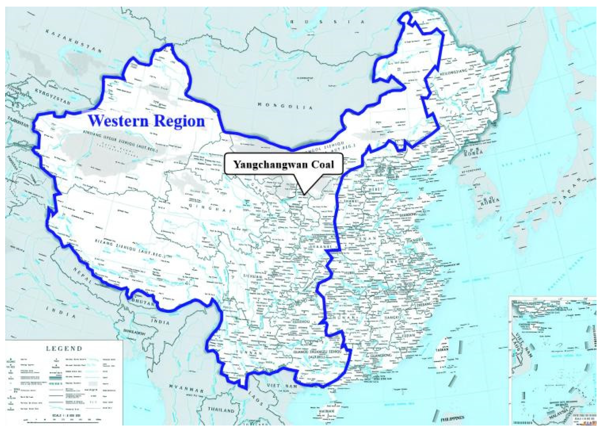
2. Project Overview
3. Theoretical Analysis
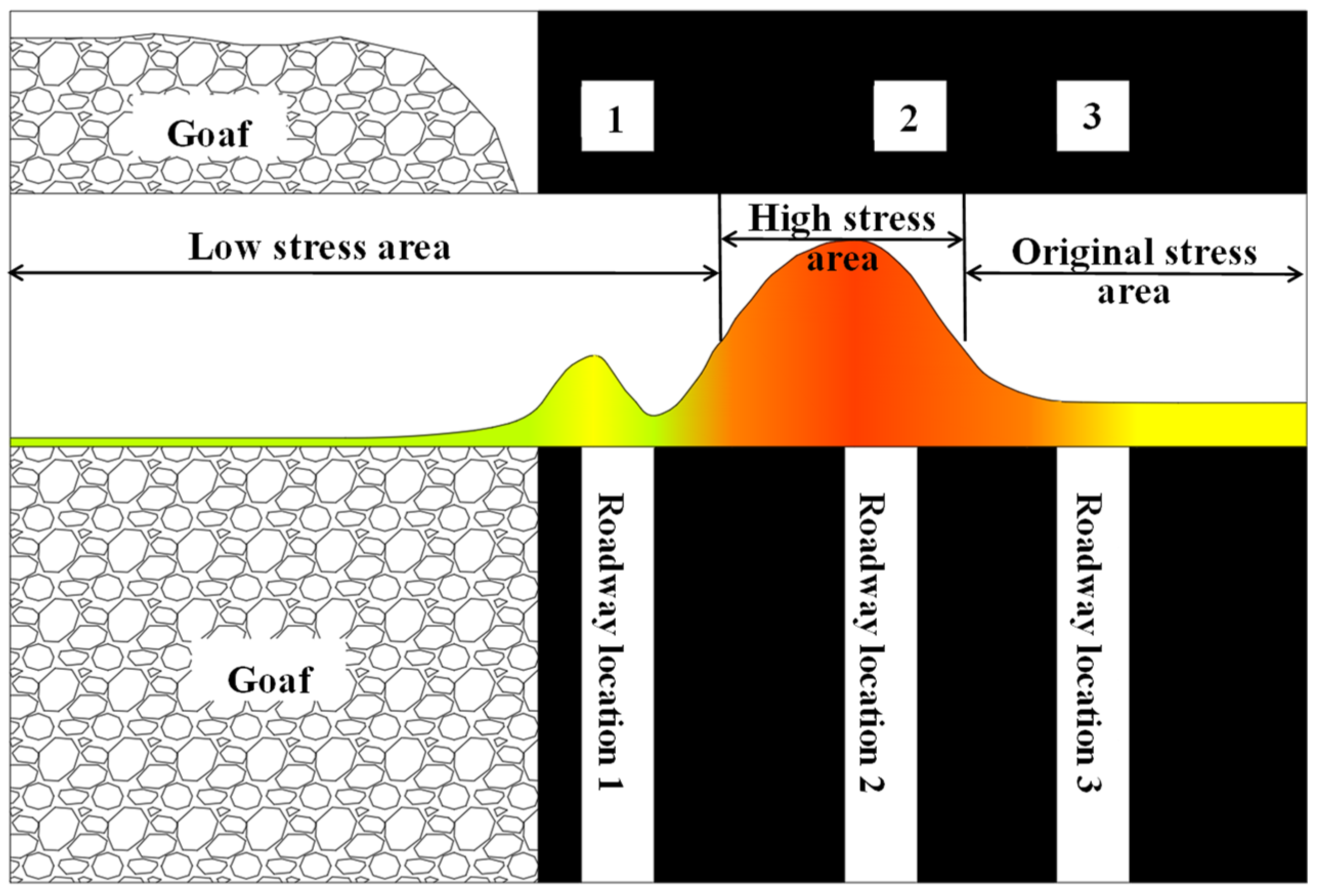
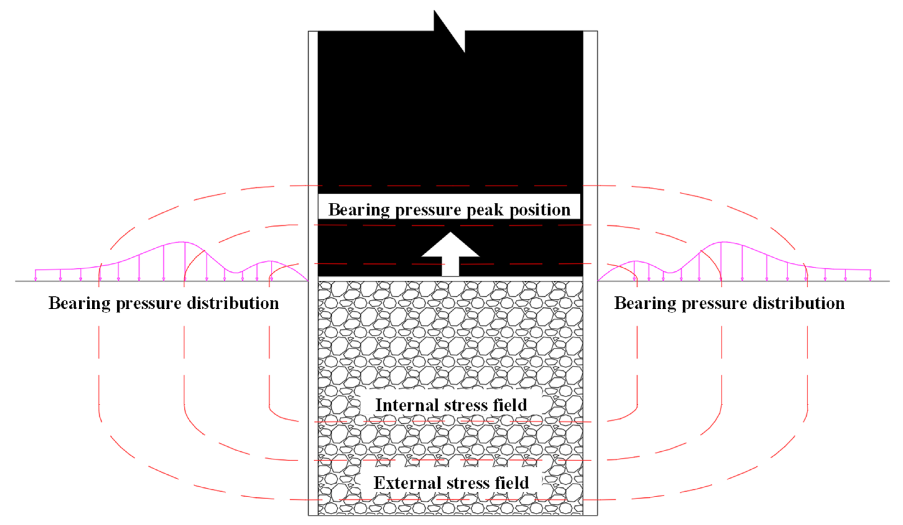
3.1. The Support Pressure Distribution Law of the Goaf Area of the Previous Working Surface
3.2. Weakly Cemented Return Mining Roadway Width Retention Design
- 1.
- Mechanical model of weak cementation return mining roadway failure
- 2.
- Analysis of mine pressure monitoring results on adjacent working surfaces
4. Numerical Simulation Calculation
4.1. Numerical Simulation Analysis of Coal Column Stability in a Weakly Cemented Environment
- 1.
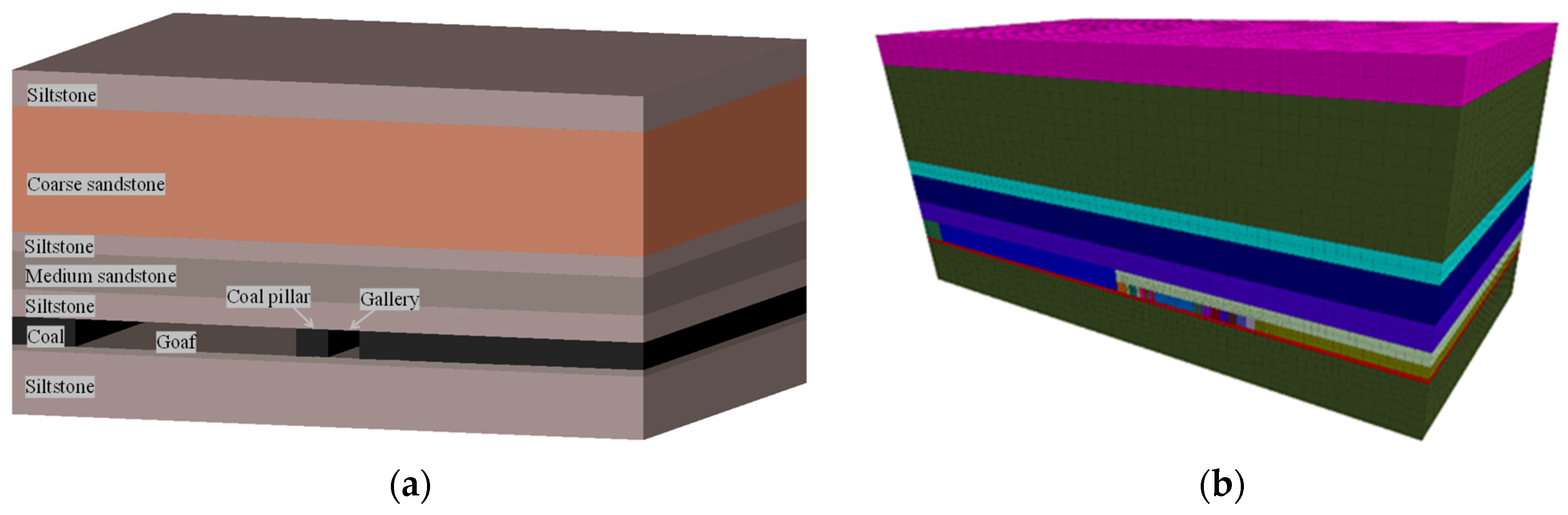
- Numerical model establishment and roadway excavation design
- 2.
- Support scheme
- 3.
- Simulation scenario
4.2. Analysis of Numerical Simulation Results
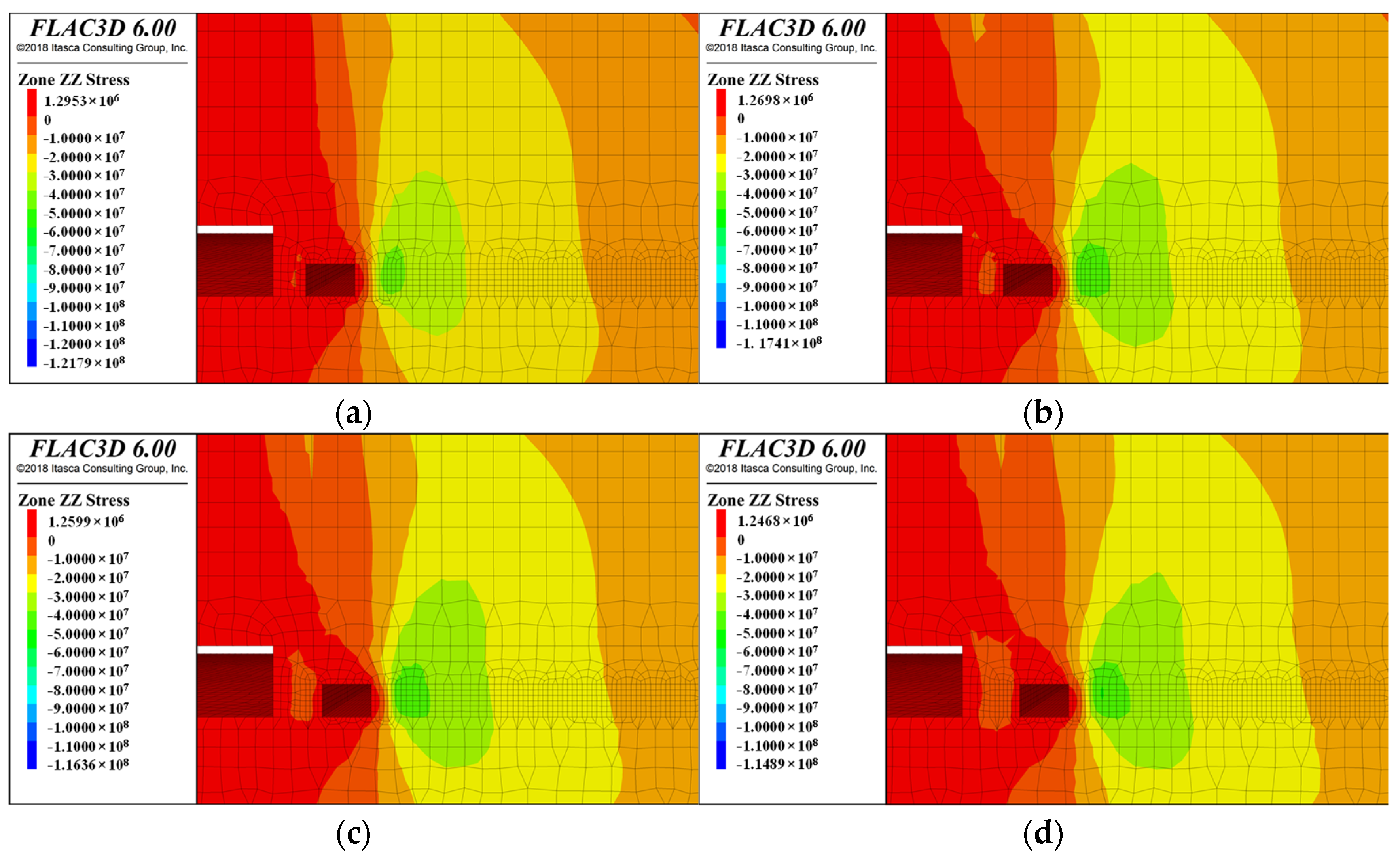
- 1.
- Stress distribution of roadways with coal pillars of different widths
- 2.
- Displacement analysis for coal column roadways of different widths
5. Field Monitoring and Analysis
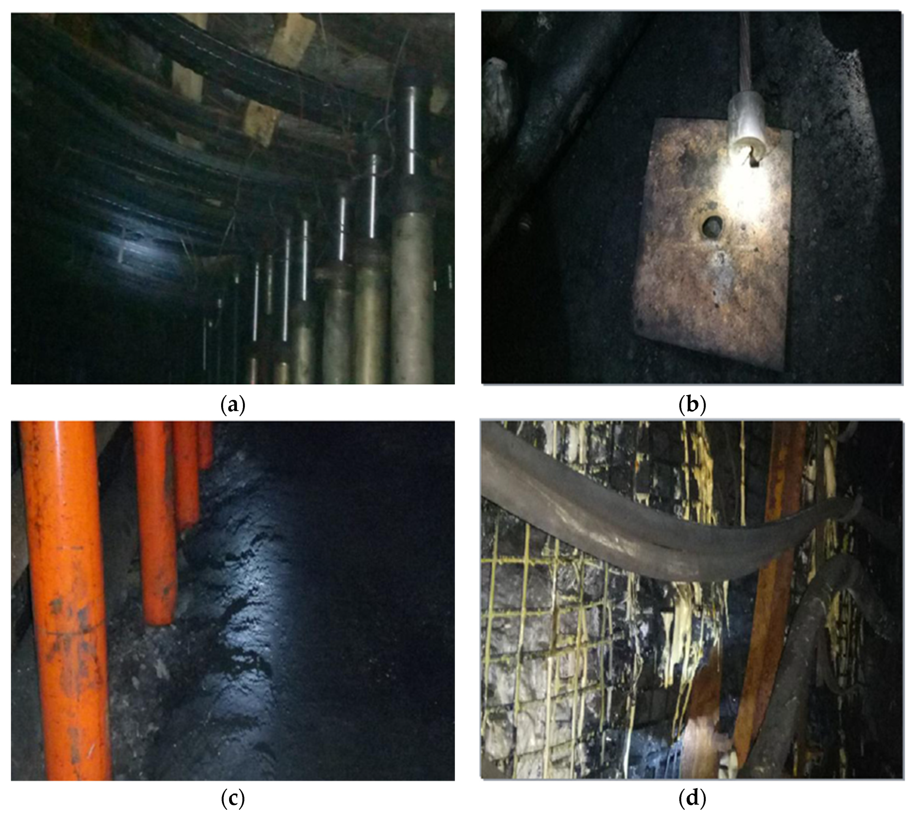
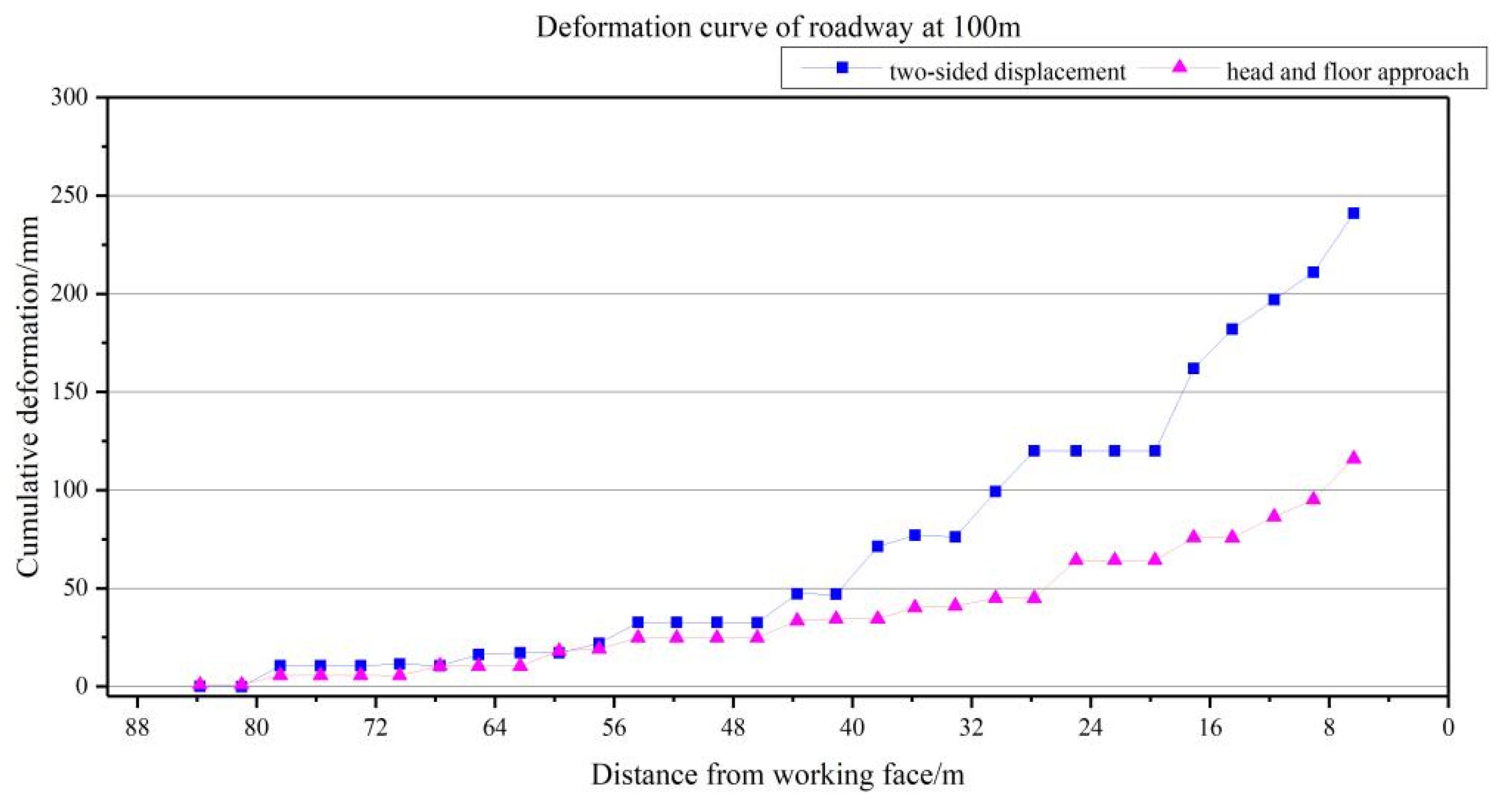
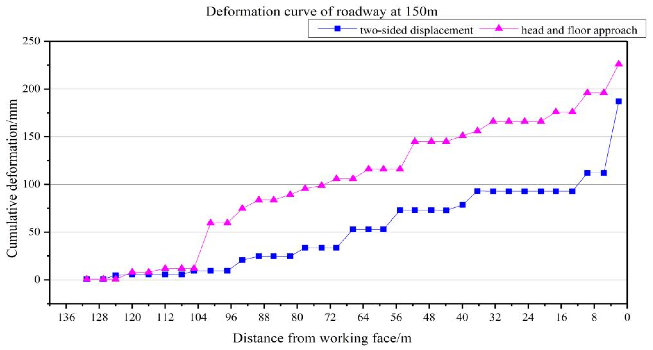
5.1. Deformation Analysis of the Surrounding Rock along the Empty Excavation Alley
- 1.
- First item:
- 2.
- Second item:
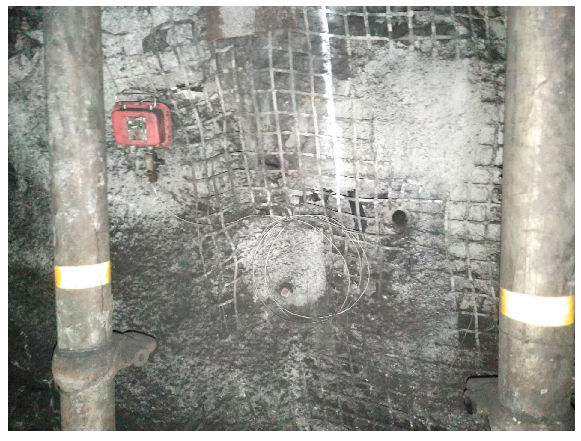
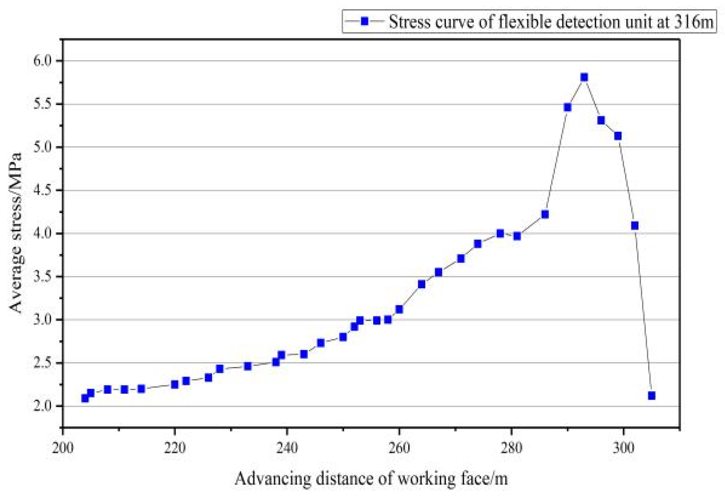
5.2. Analysis of the Upper Support Pressure in Front of the Work during the Recovery Period
6. Conclusions
Author Contributions
Funding
Institutional Review Board Statement
Informed Consent Statement
Data Availability Statement
Conflicts of Interest
References
- Wei, J.; Wu, F.; Yin, H.; Guo, J.; Xie, D.; Xiao, L. Formation and height of the interconnected fractures zone after extraction of thick coal seams with weak overburden in western China. Mine Water Environ. 2017, 36, 59–66. [Google Scholar] [CrossRef]
- Liu, Q.; Tian, J.; Liu, Y.; Jiang, Q.; Wang, M.; Liu, L. Grouting reinforcement technology of weak fractured rock mass in subway open-cut station. IOP Conf. Ser. Earth Environ. Sci. 2020, 570, 022014. [Google Scholar] [CrossRef]
- Zhu, L.; Zhao, M.; Huang, Q.; Xu, K.; Gu, W. Research on roof fracture characteristics of gob-side entry retaining with roof cutting and non-pillar mining in thick coal seam, China. Geotech. Geol. Eng. 2021, 40, 1429–1448. [Google Scholar] [CrossRef]
- Wang, Y.; Li, Y.; Yu, Z.; Zhang, H.; Ding, D. Research on the surrounding rock control technology of gob-side entry with a narrow coal pillar reserved in a fully mechanized caving face with large mining height. Geotech. Geol. Eng. 2021, 40, 285–300. [Google Scholar] [CrossRef]
- Sheng, R.; Hao, P. A case study on control technology of surrounding rock of a large section chamber under a 1200 m deep goaf in Xingdong coal mine, China. Eng. Fail. Anal. 2019, 104, 112–125. [Google Scholar]
- Mohammad, R.; Mohammad, F.; Abbas, M. A time-independent energy model to determine the height of destressed zone above the mined panel in longwall coal mining. Tunn. Undergr. Space Technol. Inc. Trenchless Technol. Res. 2015, 47, 81–92. [Google Scholar]
- Xie, G. Mechanical characteristics of macro stress shell in fully mechanized top coal caving face and its surrounding rock. J. China Coal Soc. 2005, 30, 309–313. [Google Scholar]
- Xie, G.; Yang, K.; Chang, J. Abutment pressure distribution of surrounding rock and layer thickness effect of dynamic disaster in fully mechanized top coal caving face. J. China Coal Soc. 2006, 31, 731–735. [Google Scholar]
- Sun, L.; Ji, H.; Yang, B. Physical and mechanical properties of rocks in weakly cemented strata in typical Western Mining Areas. J. China Coal Soc. 2019, 44, 866–874. [Google Scholar]
- Wang, W.; Zhao, Z.; Wang, Y.; Gao, X. Failure behavior and constitutive model of weakly consolidated soft rock. Sci. World J. 2013, 2013, 758750. [Google Scholar] [CrossRef]
- Zhao, Z.; Ma, Q.; Chen, S.; Ma, H.; Gao, X. Prediction Model of Failure Zone in Roadway Sidewall considering the Lithologic Effect of Rock Formation. Math. Probl. Eng. 2018, 2018, 9627564. [Google Scholar] [CrossRef]
- Zhao, Z.; Ma, Q.; Tan, Y.; Gao, X. Load transfer mechanism and reinforcement effect of segmentally yieldable anchorage in weakly consolidated soft rock. Simulation 2018, 95, 83–96. [Google Scholar] [CrossRef]
- Zhao, Z.; Wang, W.; Gao, X.; Yan, J. Sensitivity analysis of mechanical parameters of different rock layers to the stability of coal roadway in soft rock strata. Sci. World J. 2013, 2013, 869040. [Google Scholar] [CrossRef] [PubMed]
- Cai, J.; Zou, W.; Wen, Z. Triaxial Compressive Failure Characteristics and Constitutive Model Study of Jurassic-Cretaceous Weakly Cemented Sandstone. Adv. Civ. Eng. 2020, 2020, 8812575. [Google Scholar] [CrossRef]
- Du, B.; Liu, C.; Yang, J.; Wu, F. Abutment pressure distribution pattern and size optimization of coal pillar under repeated mining: A case study. Arab. J. Geosci. 2020, 13, 1261. [Google Scholar] [CrossRef]
- Zhu, L.; Yao, Q.; Xu, Q.; Yu, L.; Qu, Q. Large Deformation Characteristics of Surrounding Rock and Support Technology of Shallow-Buried Soft Rock Roadway: A Case Study. Appl. Sci. 2022, 12, 687. [Google Scholar] [CrossRef]
- Yang, Y.; Lai, X.; Shan, P.; Cui, F. Comprehensive analysis of dynamic instability characteristics of steeply inclined coal-rock mass. Arab. J. Geosci. 2020, 13, 241. [Google Scholar] [CrossRef]
- Ru, W.; Hu, S.; Ning, J.; Wang, J.; Gu, Q.; Guo, Y.; Zuo, J. Study on the Rheological Failure Mechanism of Weakly Cemented Soft Rock Roadway during the Mining of Close-Distance Coal Seams: A Case Study. Adv. Civ. Eng. 2020, 2020, 8885849. [Google Scholar] [CrossRef]
- Arasteh, H.; Saeedi, G.; Farsangi, M.A.E. Numerical Study of the Roof Fall and Out of Seam Dilution and Their Event Risk in a Mechanized Longwall Panel. Geotech. Geol. Eng. 2023, 41, 967–984. [Google Scholar] [CrossRef]
- Vu, T.T. Solutions to prevent face spall and roof falling in fully mechanized longwall at underground mines, Vietnam. Min. Miner. Depos. 2022, 16, 127–134. [Google Scholar] [CrossRef]
- Smoliński, A.; Malashkevych, D.; Petlovanyi, M.; Rysbekov, K.; Lozynskyi, V.; Sai, K. Research into Impact of Leaving Waste Rocks in the Mined-Out Space on the Geomechanical State of the Rock Mass Surrounding the Longwall Face. Energies 2022, 15, 9522. [Google Scholar] [CrossRef]
- Malashkevych, D.; Petlovanyi, M.; Sai, K.; Zubko, S. Research into the coal quality with a new selective mining technology of the waste rock accumulation in the mined-out area. Min. Miner. Depos. 2022, 16, 103–114. [Google Scholar] [CrossRef]
- Zhang, W. Discussion on the current situation and future development trend of coal mining technology. Sci. Technol. Innov. 2019, 24, 161–162. [Google Scholar]
- Gui, B.; Guo, J.; Chen, B. Experimental study on distribution characteristics of advance bearing pressure in 16302 face of Jisan coal mine. Coal Technol. 2007, 26, 66–68. [Google Scholar]


| Location | Lithology | Thickness/[m] | Lithological Characteristics |
|---|---|---|---|
| 1 coal | A layer of coal | 0.92 | Black, semidark briquettes, eye-shaped fracture strip structure, layered structure. The roof is a coarse sandstone aquifer at the base of the Giro Formation. |
| Main roof | Fine sandstone | 4.96 | Black-gray and composed mainly of quartz; the middle and lower parts of the development have wavy, lens-like, and small staggered layers. |
| Medium sandstone | 12.7 | The color is off-white, containing long-term minerals and mud chips, mainly gelatinous calcium; good sorting; semicircular, developmental level layer. | |
| Immediate roof | Fine sandstone | 3.23 | Dark gray, mainly composed of long-term minerals and mud chips, mud calcareous cementation. |
| Siltstone | 4.62 | Dark gray, with a thin layer of fine sandstone in the upper part and a high argilla content in the middle. | |
| False roof | Carbonaceous peat | 0.4 | Black, containing a small amount of silt and pyrite, with brittleness, angular fractures, and stratigraphic development, relatively broken. |
| 2 coal | Second layer of coal | 8.4 | Black, blocky, nonstick coal, mainly composed of semibright coal and silk charcoal, stepped fractures, striped structure, layered structure, stable deposition, simple structure. |
| Direct bottom | Siltstone | 1.44 | Black, black-gray, striped structure, block structure; the boundary line with the lower depression formation is obvious, and the coal line is partially thinned. |
| Two layers under the coal | 0.93 | Black, striped structure, broken step-like, with a clear boundary with the lower strata. | |
| Basic base | Siltstone | 10.4 | Light gray, silty structure, block structure, thin coal line. |
| Numbering | Rock Name | Thickness [m] | Depth [m] | Compressive Strength [MPa] | Tensile Strength [MPa] | Elastic Modulus [GPa] | Poisson’s Ratio | Cohesion [MPa] | Unit Weight [kg/m3] |
|---|---|---|---|---|---|---|---|---|---|
| M10 | Siltstone | 14.68 | 474.90 | 42.2 | 4.22 | 13.6 | 0.24 | 4.66 | 2.35 |
| M9 | Medium sandstone | 22.40 | 497.30 | 38.3 | 3.83 | 14.4 | 0.23 | 4.83 | 2.35 |
| M8 | Siltstone | 35.29 | 532.59 | 45.2 | 4.52 | 14.6 | 0.22 | 4.66 | 2.35 |
| M7 | Medium sandstone | 3.70 | 536.29 | 38.6 | 3.86 | 14.4 | 0.23 | 4.83 | 2.35 |
| M6 | Siltstone | 7.59 | 543.88 | 45.4 | 4.54 | 14.6 | 0.22 | 4.66 | 2.35 |
| M5 | Coarse sandstone | 39.27 | 583.15 | 37.3 | 3.73 | 14.4 | 0.23 | 4.83 | 2.35 |
| M4 | 1 coal | 1.15 | 584.30 | 15.0 | 1.5 | 1.86 | 0.25 | 0.75 | 1.5 |
| M3 | Siltstone | 5.24 | 589.54 | 45.2 | 4.52 | 14.6 | 0.23 | 4.66 | 2.35 |
| M2 | Medium sandstone | 12.00 | 601.54 | 38.6 | 4.6 | 14.4 | 0.23 | 4.83 | 2.35 |
| M1 | Siltstone | 8.56 | 610.10 | 35.7 | 3.57 | 12.5 | 0.22 | 4.27 | 2.2 |
| M0 | 2 coal | 8.70 | 618.80 | 13.0 | 1.3 | 1.86 | 0.25 | 0.87 | 1.45 |
| F1 | Siltstone | 1.45 | 620.45 | 45.2 | 4.52 | 14.6 | 0.23 | 4.66 | 2.35 |
Disclaimer/Publisher’s Note: The statements, opinions and data contained in all publications are solely those of the individual author(s) and contributor(s) and not of MDPI and/or the editor(s). MDPI and/or the editor(s) disclaim responsibility for any injury to people or property resulting from any ideas, methods, instructions or products referred to in the content. |
© 2024 by the authors. Licensee MDPI, Basel, Switzerland. This article is an open access article distributed under the terms and conditions of the Creative Commons Attribution (CC BY) license (https://creativecommons.org/licenses/by/4.0/).
Share and Cite
Zhang, B.; Zhang, S.; Shen, B.; Li, Y.; Song, S.; Han, X.; Dang, J. Simulation and On-Site Monitoring of Deformation Characteristics of Roadway Excavation along Goaf in Soft and Thick Coal Seams in Western Mining Areas. Appl. Sci. 2024, 14, 7760. https://doi.org/10.3390/app14177760
Zhang B, Zhang S, Shen B, Li Y, Song S, Han X, Dang J. Simulation and On-Site Monitoring of Deformation Characteristics of Roadway Excavation along Goaf in Soft and Thick Coal Seams in Western Mining Areas. Applied Sciences. 2024; 14(17):7760. https://doi.org/10.3390/app14177760
Chicago/Turabian StyleZhang, Buchu, Shichuan Zhang, Baotang Shen, Yangyang Li, Shilong Song, Xuexian Han, and Jinming Dang. 2024. "Simulation and On-Site Monitoring of Deformation Characteristics of Roadway Excavation along Goaf in Soft and Thick Coal Seams in Western Mining Areas" Applied Sciences 14, no. 17: 7760. https://doi.org/10.3390/app14177760
APA StyleZhang, B., Zhang, S., Shen, B., Li, Y., Song, S., Han, X., & Dang, J. (2024). Simulation and On-Site Monitoring of Deformation Characteristics of Roadway Excavation along Goaf in Soft and Thick Coal Seams in Western Mining Areas. Applied Sciences, 14(17), 7760. https://doi.org/10.3390/app14177760