Article

Solution of Water Inflow and Water Level Outside the Curtain of Strip Foundation Pit with Suspended Waterproof Curtain in the Phreatic Aquifer

School of Civil Engineering and Architecture, Henan University of Science and Technology, Luoyang 471023, China
*
Author to whom correspondence should be addressed.
Appl. Sci. 2024, 14(17), 7918; https://doi.org/10.3390/app14177918
Submission received: 26 July 2024 / Revised: 1 September 2024 / Accepted: 3 September 2024 / Published: 5 September 2024
(This article belongs to the Special Issue Advances and Challenges in Rock Mechanics and Rock Engineering)

Abstract

:
The seepage field of a suspended waterproof curtain strip foundation pit in a deep phreatic aquifer is theoretically analyzed, and a calculation method for the foundation pit water inflow and water level outside the curtain is derived. In this paper, it is assumed that the horizontal hydraulic gradient of the seepage field above the aquiclude below the bottom of the waterproof curtain decreases linearly. The separation variable method is used to solve the seepage field in the regular area inside the foundation pit, and the hydraulic head distribution function inside the foundation pit is obtained. According to the hydraulic head distribution function inside the foundation pit, the calculation expression of the water inflow of the foundation pit is further deduced theoretically. On this basis, the improved resistance coefficient method is applied to link the water level outside the pit with the solved hydraulic head inside the pit and solved. In addition, the calculation results presented in this study are compared with the calculation results of the existing model and the measured data of the foundation pit project of Yangwan Station, which proves that the analytical method can effectively meet the requirements of engineering applications.

1. Introduction

Groundwater seepage is one of the important factors affecting the stability of foundation pits [1,2,3,4]. According to the statistics, engineering accidents caused by improper treatment of groundwater in underground engineering are as high as 40~70% [5]. A suspended waterproof curtain can prolong the groundwater seepage path, reduce the water inflow of the foundation pit, and effectively reduce the influence of groundwater on the surrounding environment of the foundation pit [6,7]. Consequently, the suspended waterproof curtain is widely utilized in foundation pit engineering [8,9,10].
With the effect of a suspended waterproof curtain and precipitation in a pit, the phreatic surface outside the pit typically takes on a funnel shape [11]. Groundwater seepage is characterized as the seepage of phreatic water to incomplete wells [12], which has high complexity. However, the relevant theories are still underdeveloped, and the water level outside the curtain is difficult to solve directly. At present, the relevant industry standards regard the diving surface outside the pit as a horizontal plane when calculating the water and soil pressure acting on the supporting structure [13,14], which does not accurately reflect the actual conditions. Therefore, it is of great significance to solve the actual water level outside the curtain and enrich the seepage field solution theory concerning suspended waterproof curtain foundation pits.
The insertion depth of a waterproof curtain is one of the factors that significantly influence the seepage field of a foundation pit [15]. Therefore, the determination of the insertion depth of a waterproof curtain is a critical task in the design stage of foundation pit engineering [16,17]. At present, research on the seepage field of foundation pits is mainly focused on the analysis of the influence of the insertion depth of a waterproof curtain on a seepage field [18,19,20,21,22,23]. Due to the difficulty of building an indoor test model that is consistent with the actual project, the cost of using the test method to analyze the seepage field of the foundation pit is high and time-consuming. Wang et al. [18] analyzed the influence of the depth of a waterproof curtain inserted into a confined aquifer and the length of the filter section of the pumping well on the change in the water level using an indoor model. Zhang et al. [19] studied the model test chamber and discussed the influence of curtain insertion depth on the parameters, such as water inflow in a foundation pit. Zhang et al. [20,21] studied and analyzed the influence of the insertion depth of the waterproof curtain on the water level drop outside the curtain and the water inflow of the foundation pit through a self-made seepage model test box. Benefiting from the rapid development of computer technology, the numerical method to solve the seepage field of foundation pits is developing rapidly. The numerical method is more flexible when solving this problem; the model parameters are easily adjustable, and simulations under different conditions can be carried out. In certain cases, it can be a substitute for costly tests, thereby saving significant time and resources. Consequently, numerical simulations are widely used to solve seepage fields in foundation pits. Luo et al. [22] carried out a finite element numerical simulation of foundation pit dewatering of the fourth phase of the DongJiaDu Tunnel in Shanghai. The three-dimensional finite element computation was translated to a computer program with Visual Fortran 90, and the computation was completed using PIV 3.0. The final simulation results were consistent with the actual situation, and the foundation pit dewatering scheme was optimized. Wang et al. [23] used FLAC3D 3.00 software to analyze the change in groundwater pressure outside the foundation pit during the dewatering of the deep foundation pit with a suspended waterproof curtain combined with engineering examples. Due to the actual stratum being a non-uniform medium and the boundary conditions being more complex, these factors make it difficult to directly apply the analytical solutions relating to seepage fields to practice. However, compared with the above methods, the analytical method is more intuitive in terms of solving the seepage field, and the seepage characteristics of a foundation pit can be directly expressed in the form of a function. Therefore, the analytical solution has important theoretical significance. Zhang et al. [24] deduced the calculation formula of water inflow in a circular foundation pit of a suspended waterproof curtain and put forward a calculation method of surface settlement considering a suspended waterproof curtain by referring to the improved resistance coefficient method. Yu et al. [25] obtained the explicit analytical solution of a two-dimensional seepage field of a foundation pit by using the superposition method and the separation variable method, combined with the continuous conditions between regions, and obtained the position of the phreatic surface outside of the pit in the solution of a seepage field considering the phreatic surface outside the pit. Based on the barrier theory and numerical simulation, Shen et al. [26] proposed a formula for calculating the hydraulic head difference between the inside and outside of a suspended curtain. However, solving the seepage field of a foundation pit using numerical methods requires significant time, and the results are not universal, which is limited in terms of practical engineering applications. In addition, the analytical theory relating to seepage type from phreatic water to incomplete wells is still not sufficiently mature. With the gradual increase in aquifer thickness, the seepage characteristics of a foundation pit will change dramatically. The assumption that the hydraulic head from the bottom of a waterproof curtain to the top of the aquiclude is a fixed value adopted by many scholars in the solution process will be quite different from real situations.
Based on the current state of the research, this paper assumes that the horizontal hydraulic gradient of the seepage field above the aquiclude below the bottom of a waterproof curtain decreases linearly. The separation variable method is used to solve the seepage field in the regular area of the foundation pit, and the calculation expression of the water inflow of the foundation pit is further deduced. On this basis, the improved resistance coefficient method is used to establish the relationship between the water level outside the curtain and the solved hydraulic head in the pit. The calculation results are compared with the calculation results of the existing model and the measured data of the foundation pit project of Yangwan Station. The rationality of the calculation results is verified.

2. Solution of Foundation Pit Seepage Field

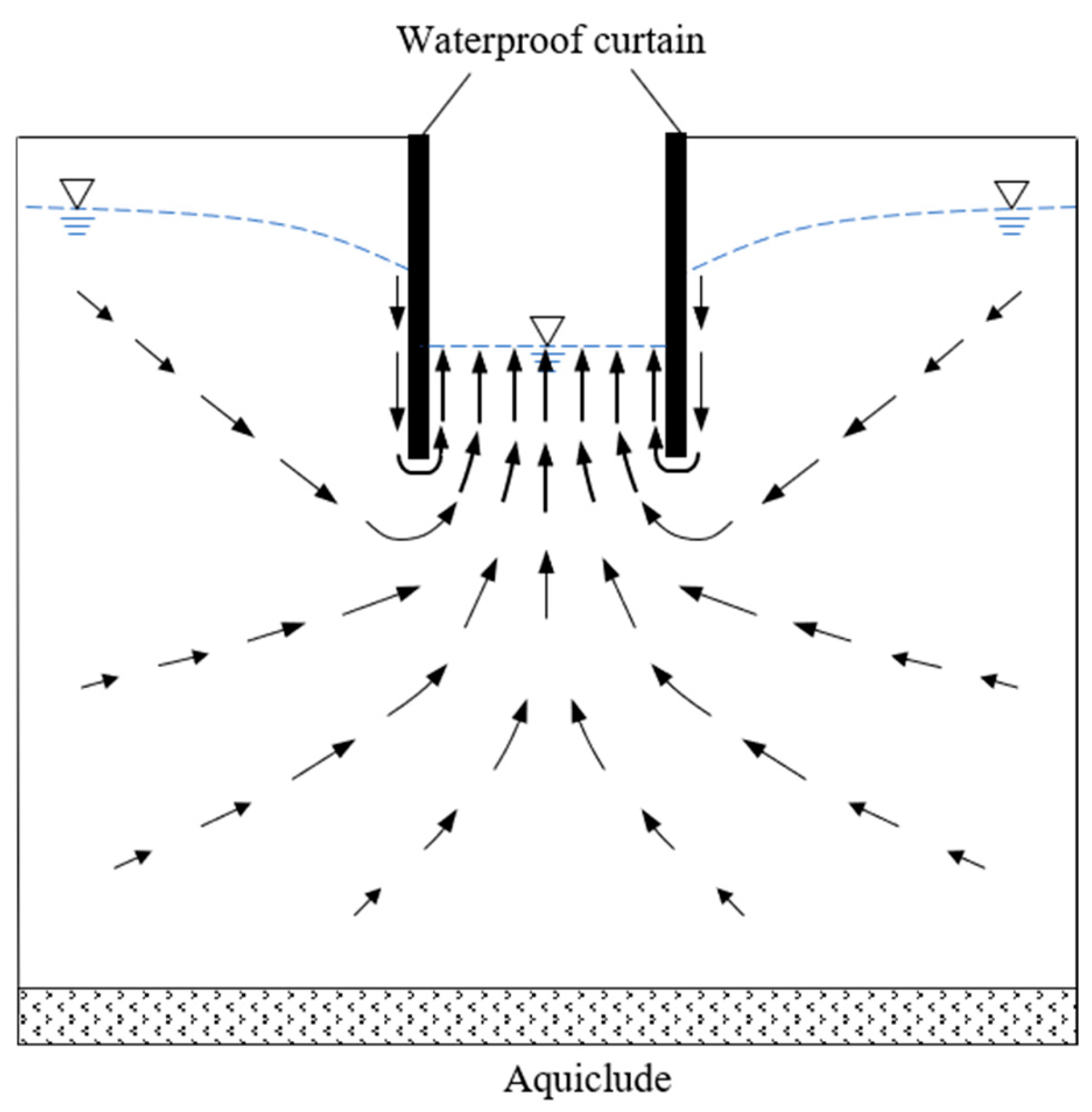
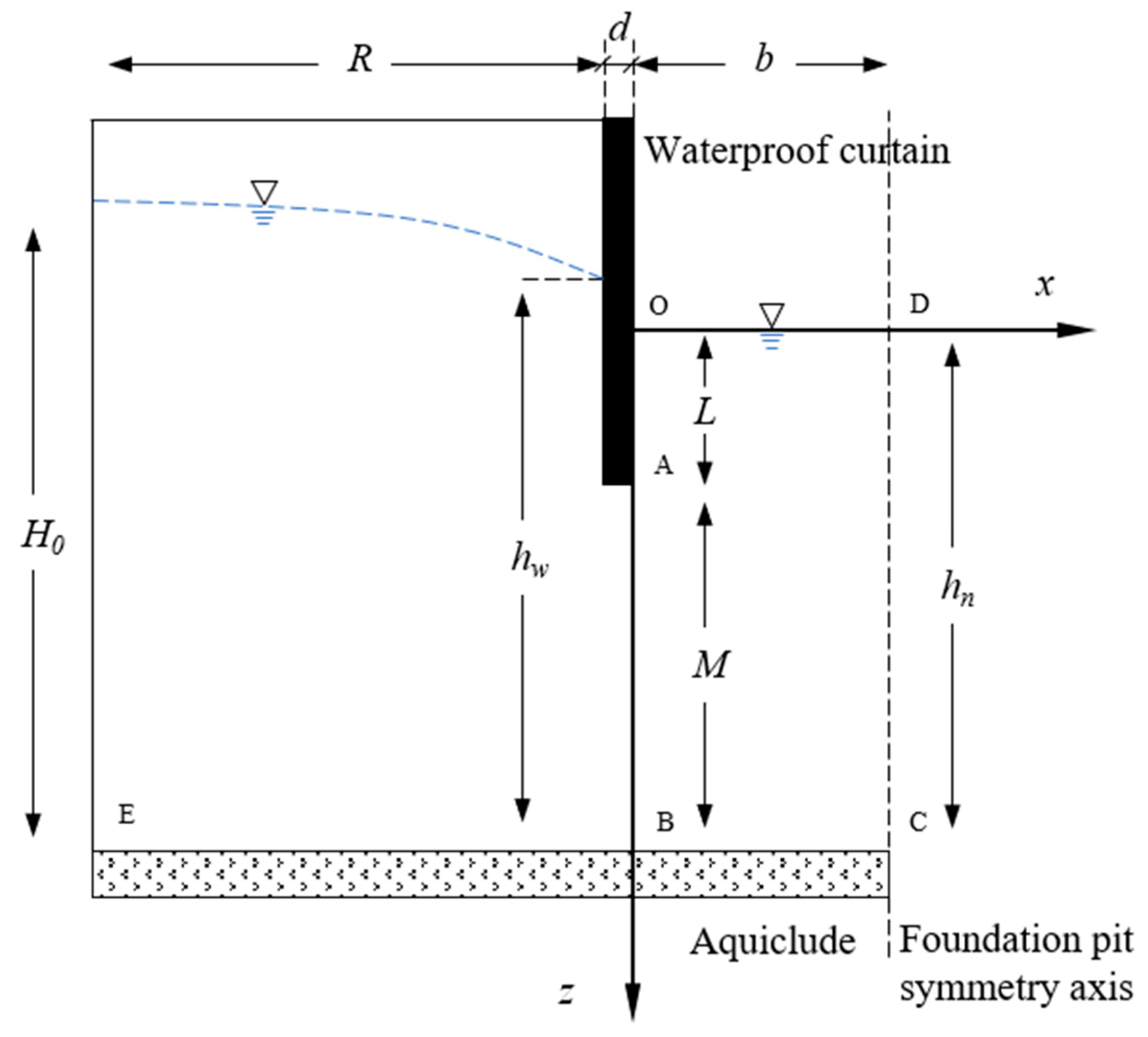
2.1. Establishment and Solution of Theoretical Analysis Model

Under the condition that the thickness of the flow cross-section is not particularly large, the groundwater on both sides of the foundation pit flows to the foundation pit due to the pumping effect inside the foundation pit, and the vertical velocity of the area below the waterproof curtain is negligible compared with the horizontal direction. Therefore, in some studies, the hydraulic head in the vertical direction from the bottom of the waterproof curtain to the top of the aquiclude is regarded as a constant [24,27]. With the further increase in the thickness of the aquifer, as shown in Figure 1, the groundwater flowing into the foundation pit is more from the aquifer below the foundation pit. At this time, the seepage in the vertical direction of the area below the waterproof curtain cannot be ignored. In addition, when the thickness of the flow cross-section is much larger than the depth of the waterproof curtain inserted into the aquifer, the range of pumping action inside the foundation pit is limited, and the groundwater seepage velocity at the top of the aquiclude being nearly zero. In the numerical simulation results of this kind of foundation pit, the horizontal velocity at the top of the aquiclude is approximately 0.08% of the horizontal velocity at the bottom of the waterproof curtain [11]. It can be inferred that if the thickness of the aquifer is deep enough, the groundwater velocity at the top of the aquiclude will approach zero.
A strip foundation pit was selected as the research object, and it is assumed that the stratum where the foundation pit is located is a homogeneous medium and the seepage is isotropic. For the foundation pit whose length is much larger than the width, the seepage field parallel to the width can be approximately simplified as plane seepage. Given the symmetry of the foundation pit, analysis can be conducted on only half of the structure. In order to facilitate the solution of the equation, the intersection of the water level in the pit and the waterproof curtain is taken as the coordinate origin, and the coordinate system shown in Figure 2 is established.
Where hn is the water level in the pit, hw is the water level outside the curtain, L is the water entry depth of a waterproof curtain in the pit, M is the thickness of the flow cross-section, which is equal to hnL; b is half of the width of the foundation pit, d is the width of the waterproof curtain, R is the influence radius of precipitation, and H0 is the water level at the influence radius. The above parameter units are m.
According to the geological conditions of the stratum where the foundation pit is located, and the seepage characteristics of the groundwater, the governing equation and boundary conditions of OABCD in the regular rectangular seepage area inside the foundation pit are listed. For the seepage in the phreatic aquifer, the governing equation is [28] as follows:
𝜕 2 h 𝜕 x 2 + 𝜕 2 h 𝜕 z 2 = 0 ,
The boundary conditions are as follows:
. z = 0 ,   0 x b ,   h = h n . .   z = h n , 0 x b ,   𝜕 h 𝜕 z = 0 . .   x = b ,   0 z h n , 𝜕 h 𝜕 x = 0 . a .   x = 0 ,   0 z L ,   𝜕 h 𝜕 x = 0 . b .   x = 0 ,   L z h n ,   𝜕 h 𝜕 x = J x ( z ) . ,
Boundary condition ① is the first kind of boundary condition, known as the hydraulic head boundary condition, which specifies that the hydraulic head at boundary OD is a fixed value equal to hn. Boundary condition ② and boundary condition ③ are the second kind of boundary condition, referred to as flow boundary conditions, which means that boundary BC and boundary CD are impermeable boundaries, and the water inflow is 0. Boundary condition ④ is also the second kind of boundary condition, where boundary OA is the impermeable boundary and the water inflow is 0, while boundary AB is the permeable boundary, in which Jx(z) is the horizontal hydraulic gradient distribution function from point A to point B, which quantifies the water inflow at each point along boundary AB. According to the groundwater seepage characteristics of the suspended waterproof curtain foundation pit, it can be seen that
  • The horizontal seepage gradient gradually decreases from the bottom of the foundation pit curtain to the aquiclude.
  • The gradient at the top of the aquiclude approaches zero, which is considered here to be zero.
  • The integral of the horizontal velocity on the AB section is equal to the water inflow per unit width on the side of the foundation pit, which is recorded as Q, m3/m·d.
In order to ensure the successful solution of the governing equation, it is assumed that the horizontal seepage gradient decreases linearly from point A to point B, and the horizontal seepage gradient at point B is zero; it can be assumed that the horizontal seepage gradient distribution function Jx(z) of the AB section is as follows:
J x ( z ) = k ( z h n ) ,
where k is the gradient decreasing rate. According to Darcy’s law, V x ( z ) = K J x ( z ) , K is the permeability coefficient of the formation, m/d. It can be obtained from the integral of the horizontal flow velocity over the AB section equal to the water inflow per unit width on one side of the foundation pit:
L h n V x ( z ) d z = L h n K J x ( z ) d z = Q ,
Substituting Equation (3) into Equation (4), the horizontal seepage gradient distribution function Jx(z) of the AB section can be obtained after solving the following:
J x ( z ) = 2 Q K M 2 ( z h n ) ,
The second-order linear partial differential Equation (1) is solved by using the separated variable method [29]. Assuming that the solution of Equation (1) can be expressed as h ( x , z ) = X ( x ) Z ( z ) , substituting it into Equation (1) results in the following:
d d x ( d X d x ) x = d d z ( d Z d z ) z ,
Equation (6) is denoted by X x = Z z = λ 2 , and the general solution of Equation (1) is the superposition of positive, negative, and zero cases of λ 2 :
h ( x , z ) = A 1 x z + B 1 x + C 1 z + D 1 + ( A 2 e λ x + B 2 e λ x ) c o s λ z + ( C 2 e λ x + D 2 e λ x ) s i n λ z + ( A 3 e λ z + B 3 e λ z ) c o s λ x + ( C 3 e λ z + D 3 e λ z ) s i n λ x ,
where Ai, Bi, Ci, and Di are constant coefficients, and i is 1, 2, and 3. Substituting the boundary conditions ①, ②, and ③ in Equation (2) into Equation (7), the following can be obtained:
𝜕 h 𝜕 x = p = 1 A p C 2 [ e A p x e A p ( 2 b x ) ] sin A p z ,
where A p = ( 2 p 1 ) π 2 h n , p = 1, 2, 3, …, ∞. Substituting the boundary conditions ④a, ④b into Equation (2) into Equation (8), the following can be obtained:
p = 1 A p C 2 ( 1 e 2 A p b ) sin A p z = 0 ; 0 z L . 2 Q K M 2 ( z h n ) ; L z h n . ,
Let the right side of the equal sign of Equation (9) be regarded as a function f(x), then the left side of the equal sign of Equation (9) can be regarded as the Fourier sine series of f(x) expansion [29], and from cos A p h n = 0 , sin A p h n = 1 , the following can be obtained:
A p C 2 ( 1 e 2 A p b ) = 2 h n 0 L 0 × sin A p z d z + L h n 2 Q K M 2 ( z h n ) × sin A p z d z = 2 h n [ 2 Q K M 2 A p 2 ( 1 sin A p L ) ] ,
The coefficient C 2 = 4 Q ( 1 sin A p L ) h n K M 2 A p 3 ( 1 e 2 A p b ) can be obtained. At this stage, the unknown coefficients have been solved. Substituting them into Equation (7), the expression for the hydraulic head distribution inside the foundation pit can be obtained:
h ( x , z ) = h n 4 Q h n K M 2 p = 1 1 sin A p L A p 3 ( 1 e 2 A p b ) [ e A p x + e A p ( 2 b x ) ] sin A p z ,
The range of x and z is as follows: 0 x b 0 z h n .

2.2. Solution of Foundation Pit Water Inflow

Analyzing Equation (11), in the design stage of foundation pit engineering, after determining the insertion depth of a suspended waterproof curtain, only the water inflow Q cannot be determined in the parameters needed in the solution process. Therefore, the next step is to solve the foundation pit water inflow Q by combining the seepage characteristics of the foundation pit with a suspended waterproof curtain.
In the process of foundation pit dewatering in the actual ultra-thick aquifer, the influence of pumping on the top area of the aquiclude is limited. Below the foundation pit, the groundwater seepage velocity in the vicinity of the aquiclude approaches zero, which indicates that the upper area of the aquiclude is similar to the still water area, and the hydraulic head is approximately equal. Therefore, in Figure 2, the EC section can be regarded as an equal hydraulic head line, and its hydraulic head value is equal to the aquifer thickness H0.
According to the hydraulic head value of EC section is equal to H0, it can be known that h 0 , h n = H 0 , and substituting it into Equation (11), the following can be obtained:
H 0 = h n 4 Q h n K M 2 p = 1 1 sin A p L A p 3 ( 1 e 2 A p b ) [ 1 + e 2 A p b ] ,
The water inflow per unit width on the side of the foundation pit can be obtained by sorting out Equation (12):
Q = ( h n H 0 ) h n K M 2 4 p = 1 1 sin A p L A p 3 ( 1 e 2 A p b ) [ 1 + e 2 A p b ] .

3. Improved Resistance Coefficient Method and Solution of Water Level Outside the Curtain

The goal of this paper is to solve the water level outside the curtain. The seepage field inside the foundation pit has been solved, and the improved resistance coefficient method can connect the water level outside the curtain with the hydraulic head inside the foundation pit. Consequently, this paper subsequently applies the improved resistance coefficient method to calculate the water level outside the curtain.

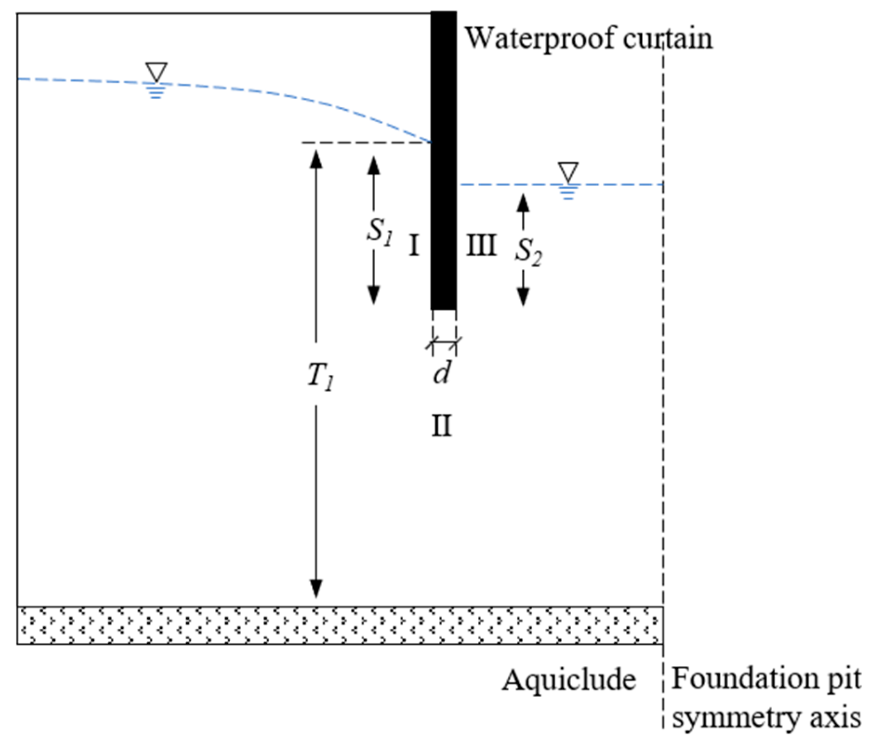
3.1. Improved Resistance Coefficient Method

According to the groundwater seepage characteristics, the seepage path is divided into different seepage sections, and the resistance coefficient of each seepage section can be calculated, respectively, according to the resistance coefficient of the weight of the allocation of the hydraulic head loss, which is the basic principle of improving the resistance coefficient method [30]. The resistance coefficient of the groundwater seepage path is divided into different seepage sections. Specifically, it can be expressed in the following equation:
Δ h i = ζ i ζ i Δ H = ζ i Q K ,
where Δ h i is the hydraulic head loss of section i, ζ i is the resistance coefficient of section i, Δ H is the total hydraulic head loss, and the meaning of Q and K is the same as before. Based on the improved resistance coefficient method, Yan [31] divided the groundwater seepage path in the foundation pit of the suspended waterproof curtain into three sections, which are summarized as the inlet and outlet seepage section and the horizontal seepage section. The calculation method of the resistance coefficient of each seepage section is given, and the application of the improved resistance coefficient method in solving the seepage field of the foundation pit with a suspended waterproof curtain is realized.

3.2. Solution of Water Level Outside the Curtain

Based on the improved resistance coefficient method, this study divides the groundwater seepage path, as shown in Figure 3, into three sections: I, II, and III:
Section I is the seepage of groundwater from the water level outside the curtain to the bottom of the waterproof curtain, which is the same as the form of the inlet and outlet seepage section summarized by Yan [31]. Therefore, the resistance coefficient of Section I is calculated directly using the calculation formula of the resistance coefficient of the inlet and outlet section:
ζ 1 = 1.5 ( S 1 T 1 ) 1.5 + 0.441 ,
Section II is the seepage of groundwater from the outside of the foundation pit to the inside of the foundation pit at the bottom of the waterproof curtain. The calculation formula of the resistance coefficient of the horizontal seepage section is as follows:
ζ 2 = d 0.7 S 1 + S 2 T 1 ,
where d is the width of the waterproof curtain; S1 is the vertical depth of penetration outside the curtain, which is equal to the difference between the water level outside the curtain and the thickness of the flow cross-section: S 1 = h w M ; S2 is the vertical depth of penetration inside the curtain, which is equal to the difference between the water level of the pit and the thickness of the flow cross-section: S 2 = h n M ; and T1 is the calculated depth of the foundation, which is equal to the water level outside the curtain hw. The units used for the above parameter are m.
In the suspended waterproof curtain foundation pit, the length of the horizontal seepage section is relatively short. Obviously, d < 0.7 (S1 + S2). According to the calculation formula of the horizontal seepage section resistance coefficient, the calculation result is negative; thus, take ζ 2 = 0 . That is, the hydraulic head loss of this seepage section can be regarded as zero, and the hydraulic head of the starting and ending points is equal. In the subsequent calculation, this seepage section can be ignored, and the hydraulic head of the starting and ending points of the horizontal seepage section is h0.
Section III is the seepage of groundwater from the bottom of the waterproof curtain to the bottom of the foundation pit. This section is located in the seepage field of the foundation pit. According to Equation (11), the loss relating to the hydraulic head of this section can be obtained. According to the relationship between the resistance coefficient and the water inflow of the foundation pit, the value of the resistance coefficient can be directly obtained. The hydraulic head loss of Section I and Section III is Δ h 1 = h w h 0 , Δ h 3 = h 0 h n respectively, and the total hydraulic head loss is Δ H = h w h n . In conjunction with Equation (14), the calculation formula of the Section III resistance coefficient can be obtained as follows:
ζ 3 = Δ h 3 K Q = 4 ( h 0 h n ) p = 1 1 sin A p L A p 3 ( 1 e 2 A p b ) [ 1 + e 2 A p b ] ( h n H 0 ) h n M 2 ,
According to Equation (14), there are the following relations:
Δ h 1 Δ h 3 = h w h 0 h 0 h n = ζ 1 ζ 3 ,
After ζ 3 is obtained using Formula (17), it is substituted into Equation (18), and in conjunction with Formula (15), the following can be obtained:
h w h 0 h 0 h n = 1.5 ( h w M h w ) 1.5 + 0.441 ζ 3 ,
Equation (19) is an implicit equation about hw. Substituting the values of parameters h0, hn, M, and ζ 3 into the equation, the value of hw can be obtained via program iteration.

4. Engineering Example Verification

4.1. Project Overview

Yangwan Station is situated beneath the north section of Zhongzhou East Road in Luoyang City. It is the terminal station of Luoyang Metro Line 1. The groundwater type of the site is characterized as Quaternary pore phreatic water, which mainly occurs in the sandy pebble layer and has strong permeability. According to the geological survey report relating to Yangwan Station, the groundwater level is located 10 m below the ground surface; the thickness of the aquifer is about 90 m, and the permeability coefficient of the stratum is about 60 m/d. The foundation pit support form of Yangwan Station is a secant pile with internal support. The width of the support structure is 1 m, and the depth of the support structure is 28 m; the thickness of the flow cross-section is 72 m. The total length of the station is 432.3 m, the total width of the standard section of the structure is 20.7 m, and the depth is about 18 m. The layout of the precipitation wells is as follows:
On 28 April 2018, the dewatering wells in the foundation pit were D1~J7 and D73~79. The water level elevation in the foundation pit at the west end is 8.38 m lower than the initial groundwater level elevation; that is, the water level in the pit is stable at 81.62 m. It can be seen that the depth of the waterproof curtain inserted into the groundwater in the pit is 9.62 m. The results of water yield measurement of precipitation wells are as follows:
According to Table 1, the total water inflow is 724.9 m3/h, while the precipitation length cannot be calculated accurately. Based on the actual prediction of the project, the precipitation length of the D1 precipitation well and the D73 precipitation well on the east side of the pit is the spacing of the two neighboring precipitation wells: 15 m. The total precipitation length is the width of the west end of the pit and the length of the precipitation of the two sides of the pit, as illustrated in Figure 4; the total length of precipitation is about 221.8 m. The water inflow per unit width Q is the ratio of the total water inflow to the total precipitation length:
Q = 3.27 m 3 / m h = 78.44 m 3 / m d ,
According to the field-measured data, the water level elevation in the R6 observation well is 4.08 m lower than the initial water level elevation. That is, the water level of the R6 observation well is 85.92 m, and there is still a distance between the R6 observation well and the waterproof curtain of the foundation pit. Therefore, the actual water level outside the curtain will be slightly lower than this value. In the subsequent verification, the reduction in the water level from the observation well to the waterproof curtain is ignored, and the water level outside the curtain is 85.92 m.
According to the project overview, the values of the parameters in the calculation model are as follows:

4.2. Comparison of Engineering Measured Data and Calculation Results

Substituting the parameters shown in Table 2 into Equation (13), the water inflow per unit width of the foundation pit is 90.55 m3/m·d.
Taking x = 0 m and z = 9.62 m, according to Equation (11), the hydraulic head value at the bottom of the curtain can be obtained as h0 = 83.19 m. Substituting h0 = 83.19 m and the parameters shown in Table 2 into Formula (17), the resistance coefficient ζ 3 = 1.0403 can be obtained. Then, ζ 3 = 1.0403 and the parameters shown in Table 2 are substituted into Equation (19), and the program iteration method is used to obtain the hydraulic head value of hw = 83.98 m outside the curtain.
In order to enhance the reliability of the conclusions of this study, the research results of Wang Junhui [27] were utilized to calculate the water inflow of the foundation pit, and the results were compared with the calculation results of this paper. The calculation formula used for water inflow requires the influence radius of foundation pit dewatering. According to the current criterion [32], the influence radius of foundation pit dewatering can be calculated to be 1232 m. The parameters shown in Table 2 are substituted into the calculation formula of water inflow, and the calculation result of water inflow is 34.70 m3/m·d. Based on the calculation method of the water level outside the curtain in this paper, the value of the water level outside the curtain under water inflow is 82.99 m. The calculation results of this paper, the calculation results of Wang Junhui’s formula, and the measured results are compared and analyzed, as shown in Table 3:
The calculated value of the water inflow per unit width of the foundation pit is 90.55 m3/m·d, which is 15.44% larger than the measured value of 78.44 m3/m·d, which is on the safe side for the design of this project, while the calculated value of the water level outside the curtain is 83.98 m, which is 2.26% smaller than the measured value of 85.92 m. Wang Junhui assumes that the hydraulic head in the vertical direction from the bottom of the waterproof curtain to the top of the aquiclude is regarded as a fixed value, which is different from the assumption of this paper; thus, the calculation results are also different. In the calculation results of Wang Junhui’s formula, the final calculation result of water inflow is 55.76% smaller than the measured value, while the calculated value of the water level drawdown outside the curtain is 82.99 m, which is 3.41% smaller than the measured value of 85.92 m. Relatively, the calculation results in this paper are more accurate. Currently, the seepage theory of a foundation pit with a suspended waterproof curtain is still not sufficiently developed. The calculation method used for foundation pit water inflow under a suspended waterproof curtain is not specified in the current criterion [32]. Consequently, in the actual project, the water inflow used during the design phase often has a high degree of error. According to the engineering experience, an error of 15.44% is within the acceptable range.
When solving the hydraulic head distribution function, the series in the function is an infinite series. The mathematical characteristics of the hydraulic head distribution function are analyzed, and it can be seen that as the number of stages p increases, the growth rate of head h tends to decrease with smaller and smaller increments.
After a trial calculation, when p takes 10, the hydraulic head increment is not in an order of magnitude with the hydraulic head value h; therefore, the calculation takes p = 50 to meet the accuracy requirements. When substituting the parameters in Table 2 into Equation (11), and drawing the equal hydraulic head line inside the foundation pit according to the calculation results, as shown in Figure 5a, the x and z axes are consistent with Figure 2.
To verify the rationality of the hydraulic head distribution results under conditions of non-extreme aquifer thickness, the thickness of the flow cross-section M is set to 12 m, and, accordingly, the water level in the pit is adjusted to 21.62 m, the thickness of the aquifer is adjusted to 30 m, and the other parameters remain unchanged when calculating the hydraulic head distribution. The results are illustrated in Figure 5b. It can be observed that the change trend in the medium hydraulic head line in Figure 5b is similar to that reported by Yu [25] and others, which verifies the correctness of the calculation results from the side. Based on the hydraulic head distribution results of the calculation model established using the foundation pit of Yangwan Station, it is noted that due to the significant volume of groundwater, the impact of groundwater seepage on the overall seepage field is minimal, leading to a small range of variation in the equal hydraulic head line.

5. Conclusions

In this paper, a theoretical analysis and solution for a suspended waterproof curtain strip foundation pit in a deep aquifer are obtained, leading to the following conclusions:
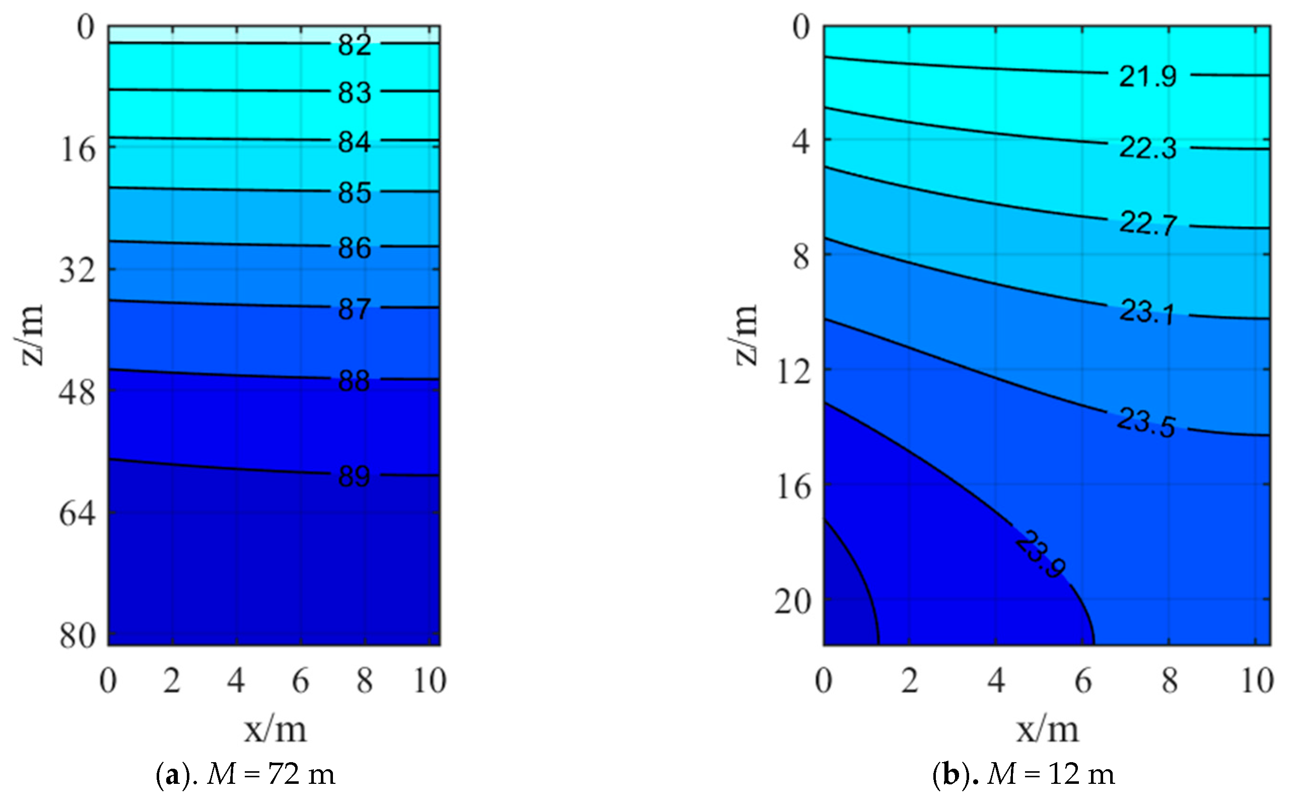
  • Based on the seepage characteristics of a foundation pit with a suspended waterproof curtain in a deep aquifer, it is assumed that the horizontal hydraulic gradient decreases linearly from the bottom of the waterproof curtain to the top of the aquiclude. The seepage field is solved using the separation variable method, and the distribution function of the hydraulic head inside the foundation pit is obtained.
  • Based on the distribution function of a hydraulic head inside the foundation pit, the calculation expression of water inflow per unit width of a suspended waterproof curtain strip foundation pit is derived. By using the improved resistance coefficient method, the water level outside the curtain is connected with the solved hydraulic head in the pit and solved.
  • The calculation results of the water inflow per unit width of the foundation pit and the water level outside the curtain, as well as the calculation results of the existing model, are compared with the measured data of the project, and the error of the calculation results of this paper is within the acceptable range, which proves the rationality of the solution method provided in this paper.
In the derivation process provided in this paper, it is assumed that the horizontal hydraulic gradient from the bottom of the curtain to the top of the aquiclude decreases linearly, which is different from the actual situation. On the other hand, it is assumed that the hydraulic head at the top of the aquiclude is equal to the thickness of the aquifer, which will also cause some errors in the calculation results of water inflow. Although the above assumptions will cause errors in the results, according to the measured data of the project, the errors in the final calculation results are within the allowable range. In addition, the object of this paper is the suspended waterproof curtain strip foundation pit in a deep aquifer, which has certain limitations in practical engineering applications.

Author Contributions

Methodology, D.L. and N.L.; software, N.L.; validation, D.L. and J.H.; formal analysis, J.S.; writing—original draft preparation, D.L. and N.L.; supervision, D.L. and J.H. All authors have read and agreed to the published version of the manuscript.

Funding

This work was supported by the National Key R&D Project: Research and Development of Intelligent Interconnected Equipment Network Collaborative Manufacturing/Operation and Maintenance Integration Technology and Platform (No. 2020YFB1712105), and the National Key R&D Project: Theory and Method of Underground Space Development and Construction (No. 2019YFC0605104).

Institutional Review Board Statement

Not applicable.

Informed Consent Statement

Not applicable.

Data Availability Statement

The data that support the findings of this study are available from the corresponding author.

Acknowledgments

We sincerely thank all the reviewers and editors for their professional comments and suggestions regarding this manuscript.

Conflicts of Interest

The authors declare no conflicts of interest.

References

  1. Liu, K. Study on the Influence of Foundation Pit Deformation Triggered by Water-Rich Strata Precipitation. Master’s Thesis, East China Jiaotong University, Nanchang, China, 2023. [Google Scholar] [CrossRef]
  2. Du, S.; Liu, P.; Wang, W.; Shi, W.; Li, Q.; Li, J.; Li, J. Numerical Simulation and Analysis of the Influencing Factors of Foundation Pit Dewatering under a Coupled Radial Well and Curtain. Water 2023, 15, 1839. [Google Scholar] [CrossRef]
  3. Jiang, Y.; Gao, Y.; Yuan, Q.; Li, X.; Sun, K.; Sun, L. Simulation and Risk Assessment of Flood Disaster at the Entrance to a Rail Transit Station under Extreme Weather Conditions—A Case Study of Wanqingsha Station of Guangzhou Line 18. Water 2024, 16, 2024. [Google Scholar] [CrossRef]
  4. Li, D.; Zhao, Y.; Liu, N.; Jiao, L.; Liu, Z. Evaluation and Analysis of Seepage Stability in the Surrounding Strata of a Dewatering Foundation Pit Based on Differences in Particle Initiation Conditions. Indian Geotech. J. 2024, 1–14. [Google Scholar] [CrossRef]
  5. Chen, L. On groundwater prevention technology and case analysis. Shanxi Archit. 2021, 47, 59–60+116. [Google Scholar] [CrossRef]
  6. Xu, Y.; Shen, S.; Ren, D.; Wu, H. Analysis of Factors in Land Subsidence in Shanghai: A View Based on a Strategic Environmental Assessment. Sustainability 2016, 8, 573. [Google Scholar] [CrossRef]
  7. Yang, T.; Tong, L.; El Naggar, M.H.; Yan, X. Hydraulic head difference at two sides of suspended waterproof curtain during multi-grade dewatering of excavation. Undergr. Space 2023, 10, 137–149. [Google Scholar] [CrossRef]
  8. Wang, P.; Wu, Y.; Xu, Y. Numerical simulation analysis on settlement control by recharge in deep foundation pit with suspended waterproof curtain. J. Hefei Univ. Technol. Nat. Sci. 2023, 46, 1097–1102. [Google Scholar]
  9. Yang, K.; Xu, C.; Chi, M.; Wang, P. Analytical Analysis of the Groundwater Drawdown Difference Induced by Foundation Pit Dewatering with a Suspended Waterproof Curtain. Appl. Sci. 2022, 12, 10301. [Google Scholar] [CrossRef]
  10. Chu, Y.; Shi, J.; Ye, Z.; Liu, D. Dewatering Characteristics and Drawdown Prediction of Suspended Waterproof Curtain Foundation Pit in Soft Soil Areas. Buildings 2024, 14, 119. [Google Scholar] [CrossRef]
  11. Li, D.; Cheng, S.; Liu, N.; Liu, Z.; Sun, Y. Numerical Simulation Study on the Distribution Characteristics of Precipitation Seepage Field in Water-Rich Ultra-Thick Sand and Gravel Layer. Water 2023, 15, 3720. [Google Scholar] [CrossRef]
  12. Lin, Z.; Li, Y.; Gui, C.; Liu, J.; Qin, X. Method for steady flow of partially penetrating well in phreatic aquifer under constant flow. Chin. J. Geotech. Eng. 2013, 35, 2290–2297. [Google Scholar]
  13. Li, Z.; Zong, Y.; Wang, B. Influence of Foundation Pit Dewatering and Excavation on Deformation of Support Structure. Site Invest. Sci. Technol. 2023, 6, 19–24+42. [Google Scholar]
  14. Xiong, H.; Wu, J.; Cai, G. Study on deformation characteristics of deep excavation with suspended curtain in Yangtze River floodplain. J. Beijing Jiaotong Univ. 2023, 47, 130–137. [Google Scholar]
  15. Shi, J.; Wu, B.; Liu, Y.; Xu, S.; Hou, J.; Wang, Y.; Sun, Q.; Meng, G.; Nong, Z.; Qiu, H.; et al. Analysis of the influence of groundwater seepage on the deformation of deep foundation pit with suspended impervious curtain. Adv. Mech. Eng. 2022, 14, 16878132221085128. [Google Scholar] [CrossRef]
  16. Wang, X.; Yang, T.; Xu, Y.; Shen, S. Evaluation of optimized depth of waterproof curtain to mitigate negative impacts during dewatering. J. Hydrol. 2019, 577, 123969. [Google Scholar] [CrossRef]
  17. Wu, Y.; Shen, S.; Lyu, H.; Zhou, A. Analyses of leakage effect of waterproof curtain during excavation dewatering. J. Hydrol. 2020, 583, 124582. [Google Scholar] [CrossRef]
  18. Wang, X.; Yang, T.; Xu, Y.; Yuan, Y. Laboratory test on the effect of foundation pit dewatering. J. Cent. South Univ. Sci. Technol. 2019, 50, 2823–2830. [Google Scholar]
  19. Zhang, Q.; Yan, J.; Wang, C.; Zhang, Z. Study on Indoor Model Test of Suspended Water Curtain. J. Northeast. Univ. Nat. Sci. 2020, 41, 1640–1645. [Google Scholar]
  20. Zhang, B. Study on the Characteristics of Groundwater Seepage Field in Foundation Pit Engineering. Master’s Thesis, China Academy of Building Research, Beijing, China, 2014. [Google Scholar]
  21. Zhang, B.; Yang, B.; Xue, L.; Liu, F. Experimental study on seepage characteristics of foundation pit with unclosed curtain. Build. Struct. 2022, 52, 2579–2582. [Google Scholar] [CrossRef]
  22. Luo, Z.; Zhang, Y.; Wu, Y. Finite Element Numerical Simulation of Three-Dimensional Seepage Control for Deep Foundation Pit Dewatering. J. Hydrodyn. 2008, 20, 596–602. [Google Scholar] [CrossRef]
  23. Wang, K.; Hu, L.; Lv, K. Analysis for Seepage Characteristic of Deep Foundation Pit with Hanging Impervious Purdah. Build. Sci. 2010, 26, 81–84. [Google Scholar] [CrossRef]
  24. Zhang, Z.; Qin, W.; Zhang, Q.; Guo, Y. Water Control Optimization Method of Foundation Pit with Suspended Waterproof Curtain. J. Northeast. Univ. Nat. Sci. 2021, 42, 242–251. [Google Scholar]
  25. Yu, J.; Zhang, Y.; Zheng, J.; Zhang, Z. Analytical solution of two-dimensional steady-state seepage field in a pit considering a phreatic surface. Rock Soil Mech. 2023, 44, 3109–3116. [Google Scholar] [CrossRef]
  26. Shen, S.; Wu, Y.; Misra, A. Calculation of head difference at two sides of a cut-off barrier during excavation dewatering. Comput. Geotech. 2017, 91, 192–202. [Google Scholar] [CrossRef]
  27. Wang, J.; Tao, L.; Han, X.; Zhou, H. Effect of Suspended Curtain Depth into Stratum on Discharge Rate and Its Optimum Design. J. Beijing Univ. Technol. 2015, 41, 1390–1398. [Google Scholar]
  28. Bear, J. Dynamics of Fluids in Porous Media; American Elsevier Publishing Company: New York, NY, USA, 1988. [Google Scholar]
  29. Qin, W. Study on Water Control Method and Optimization of Suspended Water Stop Curtain for Foundation Pit in Water-Rich Stratum. Master’s Thesis, Beijing University of Technology, Beijing, China, 2019. [Google Scholar]
  30. Mao, C.; Zhou, B. Improved resistance coefficient method for seepage calculation of dam foundation. J. Hydraul. Eng. 1980, 5, 51–59. [Google Scholar]
  31. Yan, R.; Li, Z.; Huang, Q. Discussion on Several Problems in Foundation Pit Dewatering with Suspended Waterproof Curtain. In Proceedings of the 2004 Shanghai Annual Conference on Soil Mechanics and Geotechnical Engineering, Shanghai, China, 1 November 2004. [Google Scholar]
  32. Ministry of Housing and Urban-Rural Development of the People’s Republic of China. Technical Specification for Retaining and Protection of Building Foundation Excavations (JGJ 120-2012); China Architecture and Building Press: Beijing, China, 2012. [Google Scholar]
Figure 1. Seepage in foundation pit with suspended waterproof curtain.
Applsci 14 07918 g001
Figure 2. Schematic diagram of coordinate system. hn—water level in the pit; hw—water level outside the curtain; L—water entry depth of a waterproof curtain in the pit; M—thickness of flow cross-section; d—width of the waterproof curtain; R—influence radius of precipitation; H0—water level at the influence radius.
Applsci 14 07918 g002
Figure 3. Schematic diagram of foundation pit seepage section division. S1—vertical depth of penetration outside the curtain; S2—vertical depth of penetration inside the curtain; T1—calculated depth of the foundation; d—width of the waterproof curtain; I, II, and III represent three seepage sections, respectively.
Applsci 14 07918 g003
Figure 4. Dewatering well layout of Yangwan Station.
Applsci 14 07918 g004
Figure 5. Schematic diagram of the equal hydraulic head line inside the foundation pit. The line in the figure represents the equal hydraulic head line, and the number on the line represents the hydraulic head value.
Applsci 14 07918 g005
Table 1. The measurement results of the water yield of the operating dewatering wells in Yangwan Station.
Dewatering Well NumberWater Inflow/m3/hDewatering Well NumberWater Inflow/m3/h
D167.8D7349.7
D240.7D7448.6
D336.2D7531.7
D463.3D7663.0
D536.3D7730.9
D672.3D7849.5
D785.9D7949.0
Table 2. Value of foundation pit parameters.
ParametersValue
Aquifer thickness H0/m90
Water level in foundation pit hn/m81.62
Stratum permeability coefficient K/m/d60
Foundation pit width 2b/m20.7
Water entry depth of a waterproof curtain in the pit L/m9.62
Flow cross-section thickness M/m72
Waterproof curtain width D/m1
Table 3. Measure value and calculating value.
Calculated ParametersMeasure ValueCalculated Value of This StudyCalculated Value of Wang Junhui’s Formula
Water inflow per unit width Q/m3/m·d78.4490.5534.70
water level outside the curtain hw/m85.9283.9882.99
Disclaimer/Publisher’s Note: The statements, opinions and data contained in all publications are solely those of the individual author(s) and contributor(s) and not of MDPI and/or the editor(s). MDPI and/or the editor(s) disclaim responsibility for any injury to people or property resulting from any ideas, methods, instructions or products referred to in the content.

