Article

Study on Roof-Cutting and Support of a Retreating Roadway under the Double Influence of Large Mining Heights

1
School of Civil Engineering and Architecture, Dalian University, Dalian 116622, China
2
Research Center for Geotechnical and Structural Engineering Technology of Liaoning Province, Dalian University, Dalian 116622, China
3
Faculty of Science and Technology, Beijing Normal University-Hong Kong Baptist University United International College, Zhuhai 519087, China
*
Author to whom correspondence should be addressed.
Appl. Sci. 2024, 14(17), 7946; https://doi.org/10.3390/app14177946
Submission received: 13 August 2024 / Revised: 29 August 2024 / Accepted: 2 September 2024 / Published: 6 September 2024
(This article belongs to the Section Civil Engineering)

Abstract

:
When the coal mining face enters the final stage of mining, the roadway faces the superimposed influence of surrounding rock stress redistribution and roof rotary moment. As affected by the strong disturbance in the coal mining process, the roof plate of the roadway has undergone serious deformation, which seriously affects the stability of the roadway. Taking the 108 working face of the Jinjitan coal mine as the engineering background, a comprehensive study was conducted on the control of the perimeter rock in the retracement of a tunnel in a heavy coal seam with a large mining height. By analyzing the physical properties of the enclosing rock of the retreated roadway, and using theoretical analysis, numerical simulation, on-site monitoring, and other methods, the characteristics of the peripheral rock’s movement relationship and mineral pressure manifestation in the final mining stage of the large-height working face have been studied. The structural mechanics model was established, and in the case where the support cannot be solved just by strengthening the support, the design scheme of “blasting roof break + constant resistance anchor cable support” was innovatively tried. FLAC3D simulation results show that the stress release of the surrounding rock is more adequate when the height of roof cutting is 20 m. The stress of the surrounding rock near the roadway is reduced by 30~40%, and the stress state is reasonable. The constant resistance and large deformation anchors can absorb the deformation energy of the rock body, maintain constant working resistance and stable deformation, and have good rock stability control, which is conducive to the stability of the roadway.

1. Introduction

In recent years, with the deepening of the depth of coal mining, surrounding rock disturbances and impact ground pressure phenomena occur frequently [1]. With the rapid increase in productivity, after the comprehensive mining face enters into the final stage, affected by the mining action of over-support and support pressure, the roof plate cracking and spalling is serious, and with the gradual increase in mining depth, the stability and safety of the deep rock layer roadway has been greatly affected [2,3,4,5,6], resulting in a large mining height, and a large cross-section of the end of the mining stage of the withdrawal of the roadways with traditional support can no longer meet the renewed demand [7]. The disruption of the original geotechnical body during the mining process is the primary source of the deformation of the roadway [8], the perimeter rock itself has a certain bearing capacity, due to the disturbance that makes the bearing capacity of the perimeter rock decreasing, and there was a need to redesign the stress distribution in the surrounding rock and the support structure [9]. At this point of the roadway support, the stability of the roadway can be enhanced by taking into account the multiple coupling of the anchors and anchor ropes’ support role with the enclosing rock body’s strength and stiffness [10].
The applications of roof cutting and pressure relief technology play a crucial role in controlling the stability of the surrounding rock of the roadway and improving the resource recovery rate [11]. Xue et al. used directional roof-cutting and pressure-reducing technology to reduce the surrounding rock pressure of the adjacent hollow dynamic pressure roadway in the end zone of the working face of an extra-thick coal seam, reducing the pressure spike and perimeter rock stress range of the adjacent hollow tunnel, as well as increasing the roadway’s stability [12]. Xiong et al.’s research results show that the elevation angle and depth of the top-cutting drill hole is 75° and 9 m, which can significantly reduce the stress peak value of the coal pillar of the guarding roadway, improve the stability of the roadway, and play a better unpressurized protection effect on the system roadway [12,13]. He et al., in an effort to solve the problem of deformation of dynamic pressure tunnel deformation influenced by a strong hard top plate, carried out numerical simulations and field tests of roof cutting and decompression, and reasonable parameters of roof cutting and decompression were determined so as to effectively control the deformation of the dynamic pressure tunnel [14]. Guo et al. systematically investigated the parameters related to the unloading of hard basic fixed-cut tops using experimental methods such as similar simulation [15]. Wang et al. used Dianping coal as an project example to investigate the movement characteristics of an overburdened rock layer under the condition of 110 workings [16]. Li et al. aimed at studying how the increase in mining depth led to the problem of mine stress showing dramatically; their use of mine stress theory analysis and numerical simulation concluded that the use of cutting the top of the pressure relief and supporting reasonable support technology can realize the stability of the surrounding rock in the stage of work face back mining [17]. Wang et al. put forward the method of directional roof cutting + high strength constraints of coal pillar free roadway without coal pillars under extremely close conditions, which effectively reduces the degree of mine pressure under extremely close conditions [18,19]. Liu et al. deduced the equation for roof subsidence by establishing the mechanical model of roof structures, and determined the calculation formulae for roof movements at different locations [20]. Guo et al. proposed the use of NPR anchor cables to compensate for the peripheral rock stress, control the penetration of nodal fissures, and then improve the strength of the rock by using more than grouting technology to increase the power of the stone, and cutting the top of the unloading pressure to reduce the force of the peripheral rock to maximize the restriction of the movement of the tunnel peripheral rock structures [21]. Hou et al. defined the critical parameters of thin coal mine roof cutting and pressure unloading by analyzing the state and force of the overlying roof collapse during the thin coal seam mining process [22]. He et al. found that when the working face burial depth exceeds the first critical value, the roadway will have a nonlinear large deformation, so roof-cutting + a U-shape support was proposed to guarantee the stability of the roadway’s peripheral rock deformation [23]. Liu et al. studied the characteristics of overburdened rock damage and fissure development in the mining airspace under the condition of roof-cutting, and the collapse height of the key rock layer and the controlled upper rock layer increased after roof-cutting, which provided sufficient support for the upper rock layer and, at the same time, reduced the proportion of fissures [24]. Wang et al. established a different uncoupling coefficient aggregation blasting model to determine the optimal charging structure; the blasting effect is good, and the waterproof coal pillar has played an excellent protective effect [25]. Bednarek, Ł et al. optimized the support design to take into account the dual effects of mining stress and vault collapse [26]. Chen et al. conducted a systematic review of the critical technical data of deep tunnel bedding, and deduced the relevant data of bedding bursting according to the “S-R” stability principle and rock crushing and expansion characteristics, to ensure smooth bedding of the lateral top plate into the roadway upon mining return [27]. Yang et al. analyzed the dynamic pressure influence brought by the mining process through the theory of roof cutting and LS-DYNA numerical analysis, and concluded that directional roof cutting, with the obvious effect of pressure unloading, can effectively control the deformation of the surrounding rock [28]. Vu T proposed the use of chemical adhesives to enhance the strength of the connection between the roof slabs and the method for improving the strength of shield support during the mining process, which effectively solved the phenomenon of roof slab collapse [29]. Cheng et al. put forward the technology of roof-cutting pressure relief + grouting reinforcement for the frequent bulging and bottom-drumming phenomenon of soft rock roadways in water-rich areas [30]. Peng et al. used three zones (A, B, C) of targeted zonal support for the retreat roadway, giving full play to the support efficiency of the anchor rods and cables, to ensure the safety and stability of the retreat roadway [31]. The wide application of roof cutting and pressure relief is due to the continuous research of scholars at home and abroad in the above-mentioned roof cutting and pressure relief technology [32].
Many scholars mainly focus on the unloading support of the transportation roadway, and there are fewer studies on the stability control of the retraction roadway of the oversized mining high working face. The 108 coal mining face is the world’s first fully mechanized mining project, with an extraordinarily high mining height of 8.2 m. The hydraulic supports used here each weigh 78.2 tons, and there is limited experience with withdrawing such supports. This situation poses significant challenges for supporting the retreating roadway, and addressing the technical issues related to the withdrawal equipment aims to address these challenges by employing advanced roof cutting blasting and pressure relief techniques to mitigate the impact of rock beam rotation and reduce mechanical connections between the goaf and the roadway roof [33]. These methods are designed to alleviate problems such as local roof falls, excessive pressure on the direct roof, and difficulties in supporting the coal wall in super-large height mining faces. Additionally, the project focuses on optimizing the support parameters for the retreating roadway to enhance overall stability and efficiency.

2. Project Overview

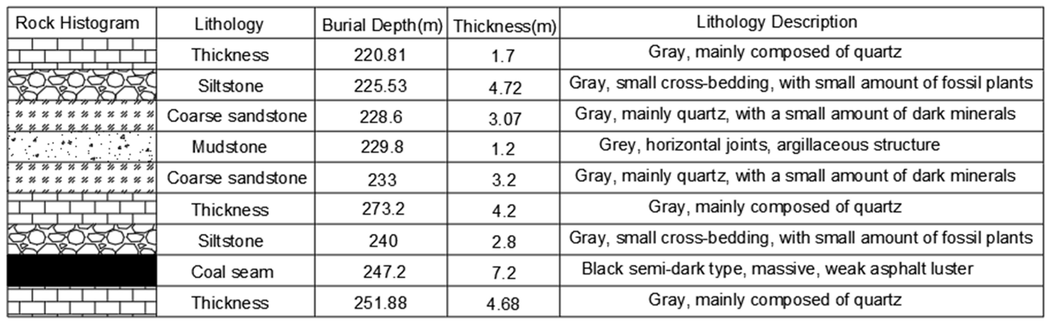
2.1. Geological Conditions

Jinjitan Coal Mine is located in Yulin City, Shaanxi Province, in China. The 12-2 Upper 108 working face is the first mining face in the southwest wing of a plate area; the average thickness of the coal seam is 7.2 m, the inclination angle of the coal seam is less than 1 ° , and the structure of the coal seam is simple; it is of the black semi-dark type, block structure, shell fracture, and weak asphalt luster; it is the more stable and extra-thick coal seam that can be mined in the whole area, the hardness of the coal is f = 2.8 , the inclined length of the working face is 300 m, and the length of the strike length is 5550 m. The 8.2 m hydraulic support is used for the mining of the face. The working face has an inclined length of 300 m and a strike length of 5550 m, and the spacing between the main and auxiliary retracement roadway was 24 m, as shown in Figure 1. The 8.2 m hydraulic support is used for large height mining. The face cuttings are designed to be dug along the bottom of the 2-2 seam, which has a nearly north direction and a nearly west wind direction, with a simple geological structure. According to the drilling data, there is no large fault at the cuttings, and the column structure of the drill holes is shown in Figure 2.

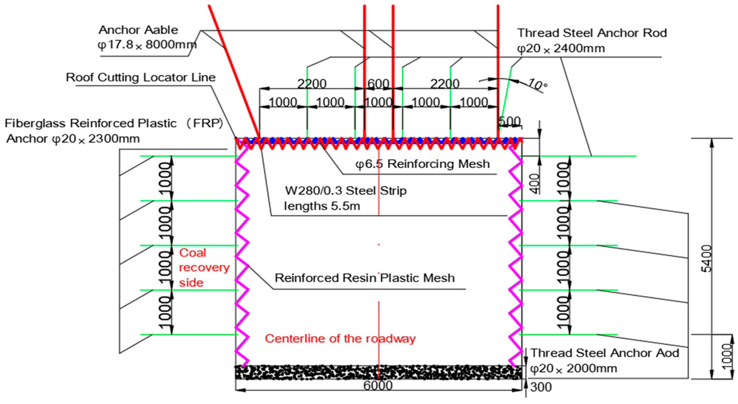
2.2. Overview of the Original Evacuation Lane Support

The 108 working face retreat passage’s support requirements are: no longitudinal bar left screw, threaded rebar anchor specifications of ϕ22 × 2400 mm, the top plate anchor design anchoring force is 60 KN, the design anchorage force of the side bolt is 50 KN, the anchor end measures 500 mm in length, the preload tightening torque is 100 N/M, and the specification of the bolt tray is 150 × 150 × 10 mm; the roof anchor cable adopts a φ17.8 × 8000 mm steel strand, the anchorage length is 1200 mm, the pre-tightening force is 100 kN, the anchorage force is not less than 200 kN, and the anchor cable tray specification is 280 × 280 × 24 mm; the main retracement channel needs to add wedge-shaped gaskets to the angle anchor cable tray on the mining side, and the reinforced polyester plastic mesh grid on the mining side is 50 × 50 mm; the reinforcement mesh specification is φ6.5 steel bar, mesh 100 × 100 mm, net lap length 100 mm, net buckle distance 200 mm, W steel belt reserved aperture φ = 40 mm. These are shown in Figure 3.

2.3. Theoretical Calculation of Support

We use the roof support strength quasi-measurement to theoretically investigate the effectiveness of roof support in the retracted roadway. The support force ( P t ) required to keep the direct roof structure stable is simplified into the weight of rock body within the height of the direct roof.
P t = γ H
In the formula, γ is the average capacity of the direct top rock, and we take γ = 47   k N / m 3 ; H is direct top thickness, and we take H = 8.1   m .
The support force provided by anchor rods and anchor cables is P z .
P z = P g + P s = δ g n g N g a g + δ s n s N s a s
P g is roof anchor support resistance, kN;
P s is the top plate anchor cable support resistance, kN;
δ g , δ s are the anchor rod and anchor cable support efficiency respectively, and we take δ g = 50 % , δ s = 60 % ;
n g , n s are the number of anchor rods and anchor cable support per unit length of the roadway roof, respectively;
Ng and Ns are the breaking force of anchor rods and anchor cables, respectively, taking N g = 60   k N and N s = 200   k N ;
a g and a s are the spacing between anchor rods and anchor cables.
The design principle of roof support is
P z K P t
K is the engineering safety coefficient, not less than 2.
According to theoretical calculations and field experiments, it is determined that the thickness of the direct roof is taken as H = 7.9   m , the width of the roadway is 6 m, the average capacity of the overlying rock layer is taken as γ = 19.2   k N / m 3 , and the minimum support force required to maintain the stability of the direct roof structure per meter of the roadway is P t = 151.68   k N , which is calculated according to Equation (2):
P z = 50 % × 5 × 60 1 × 1 + 60 % × 4 × 200 2 × 2 = 270   k N
From the design principle of roof support of Formula (3), it can be obtained that P z < 2 P t = 303.36   k N , so from the theoretical analysis, it can be seen that the support design of the original retracted roadway does not meet the requirements.

3. Model Establishment and Support Analysis

3.1. Establishment of Model and Boundary Conditions

From the relevant geological conditions of the coal seam and the lithology of the borehole histogram, FLAC3D 5.01 numerical simulation software was used to establish a simulation model of the support effect according to the geological characteristics of the 108 working face in the Jinjitan coal mine, and the corresponding physical parameters were assigned to each rock stratum, with the acceleration of gravity is taken as 9.8 m/s, the model material adopting the Mohr–Coulomb intrinsic model, and the physical and mechanical parameters of each rock stratum were as shown in Table 1.
Since the inclination angle of the coal seam is less than 1°, the inclination angle of the model is set to horizontal for the convenience of calculation, and the size with which the model is (length × height × width) 400 m × 200 m × 300 m, as shown in Figure 4.

3.2. Roadway Support Simulation Analysis

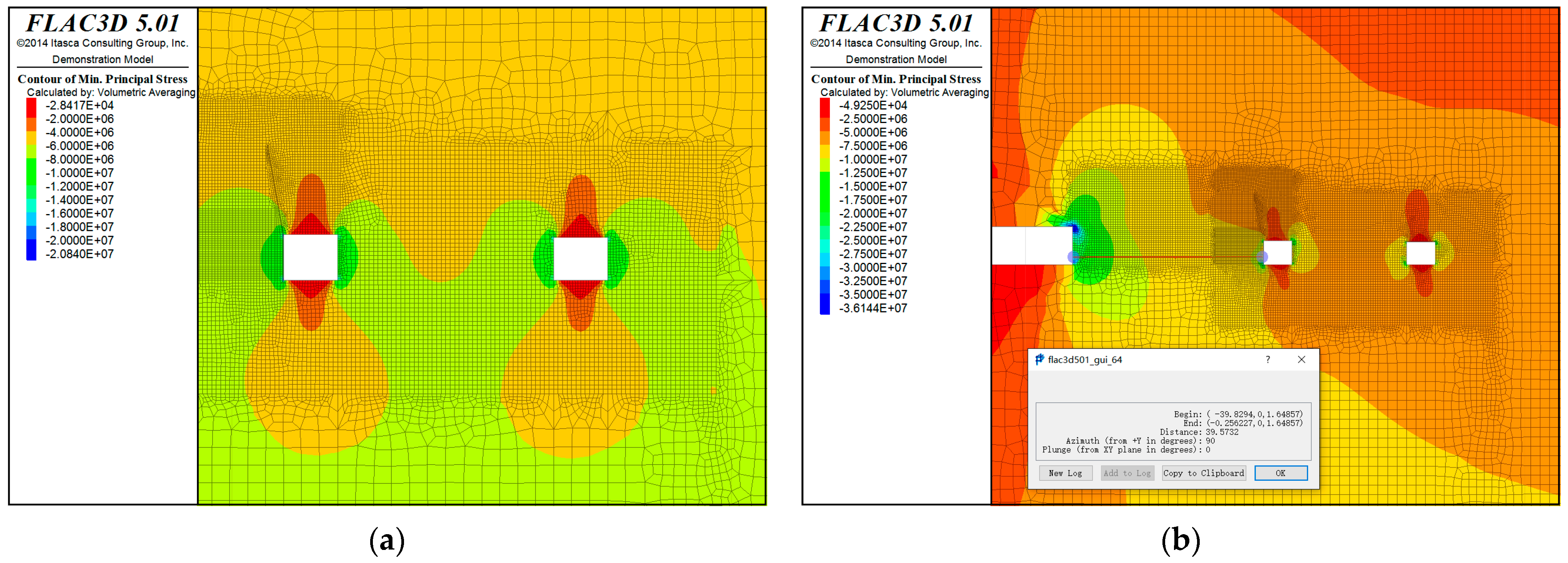
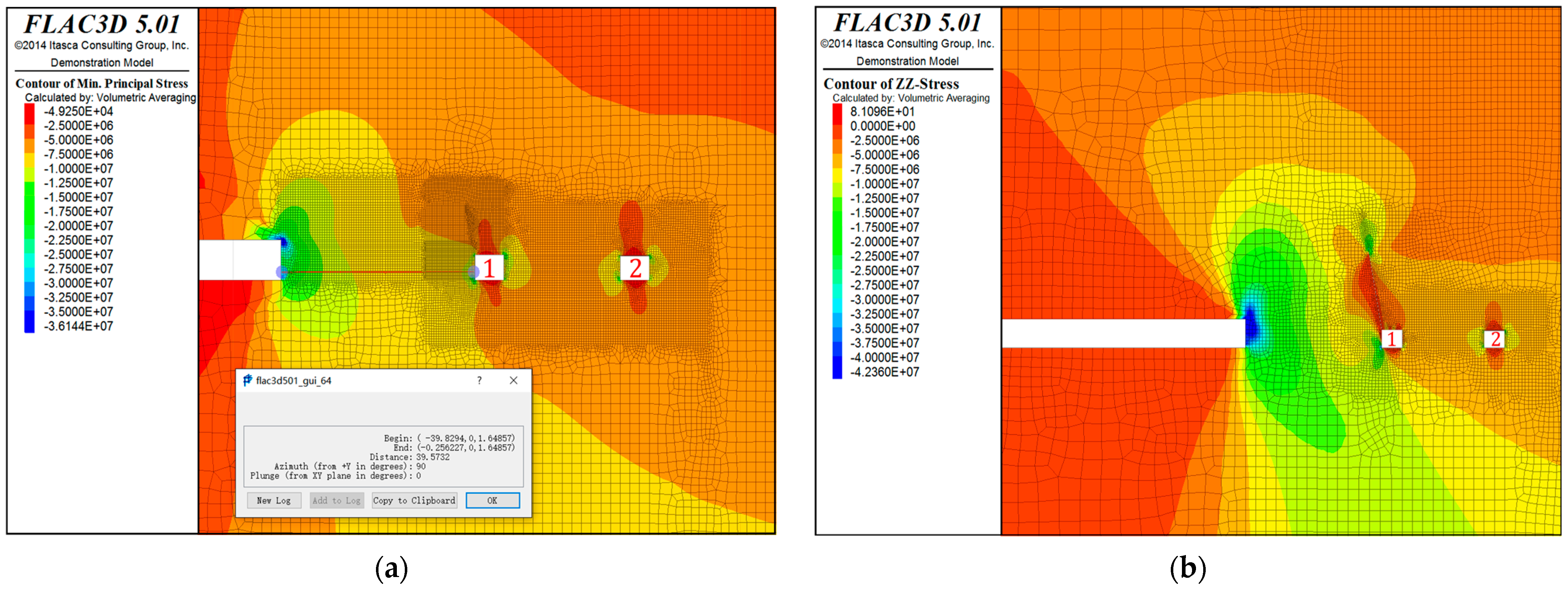
3.2.1. Surrounding Rock Stress Simulation

To fully understand the roadway support, stress distribution simulations were first performed on the roadway perimeter rock. We carry out excavation simulation for the model in Figure 3. When the working face is 200 m away from the main withdrawal channel, it can be seen from the cloud diagram of the minimum principal stress distribution of the surrounding rock that the stress state near the withdrawal channel is almost unaffected by promoting the coal mining face, and the surrounding rock of the main retraction channel and the auxiliary withdrawal channel shows that it is pressurized at the two gangs, with a maximum area of 10 MPa~13 MPa, and a tensile at the top and bottom. When the working face is 40 m away from the main retraction channel, due to the increase in the hollow area, the rotary moment of the upper rock beam increases so that the working face advancement already has a weak influence on the main retraction channel; affected by the old top pressure, the main retraction channel near the face of a gang of the main stress area moves downward, the minimum main stress of the surrounding rock near the maximum value of about 15 MPa, as Shown in Figure 5.

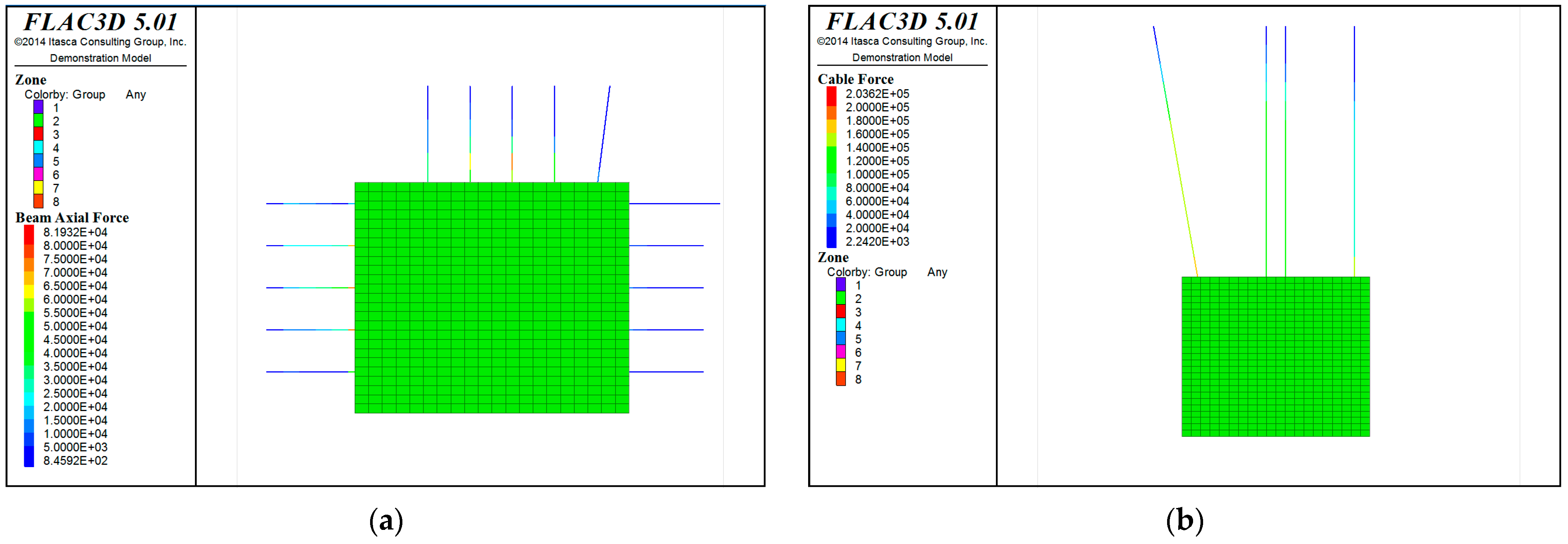
3.2.2. Support Simulation Analysis of Retracement Roadway

In this numerical calculation, the force of the bolt is expressed in the form of tension. The calculation formula between bolt stress and tension is: σ = F / A , where σ is the stress of bolt (cable), F is the tension, and A is the (cable) anchor’s cross-sectional area. The external force of the bolt support can be replicated by means of the stress generated by the advancement of the work surface on the surrounding rock of the retracement roadway.
When the mining line advances to a distance from the retreat roadway of 8 m, by the anchor force distribution diagram, it can be seen that the arch at the top of the anchor tension is the largest, the biggest value has reached 81.9 kN, and has exceeded the anchor force design value of 60 kN; pre-stressing anchors pre-stressing for 100 kN, and as the excavation surface continues to move forward, pre-stressing anchors gradually increase the force, which will exceed the pre-stressing anchors to withstand the maximum tension (200 kN). At 200 kN, the prestressing anchor cable will be pulled out, as illustrated in Figure 6.
Comprehensive calculation and simulation analysis results show that when the coal mining face is 8 m away from the retreat roadway, the force of the anchor rods and anchor cables have exceeded the limit state, resulting in instability; so, according to the existing support conditions, with the continuous advancement of the working face, the anchor rods and anchor cables used in the support will be ineffective, and it is hard to support the strength to achieve the requirements.

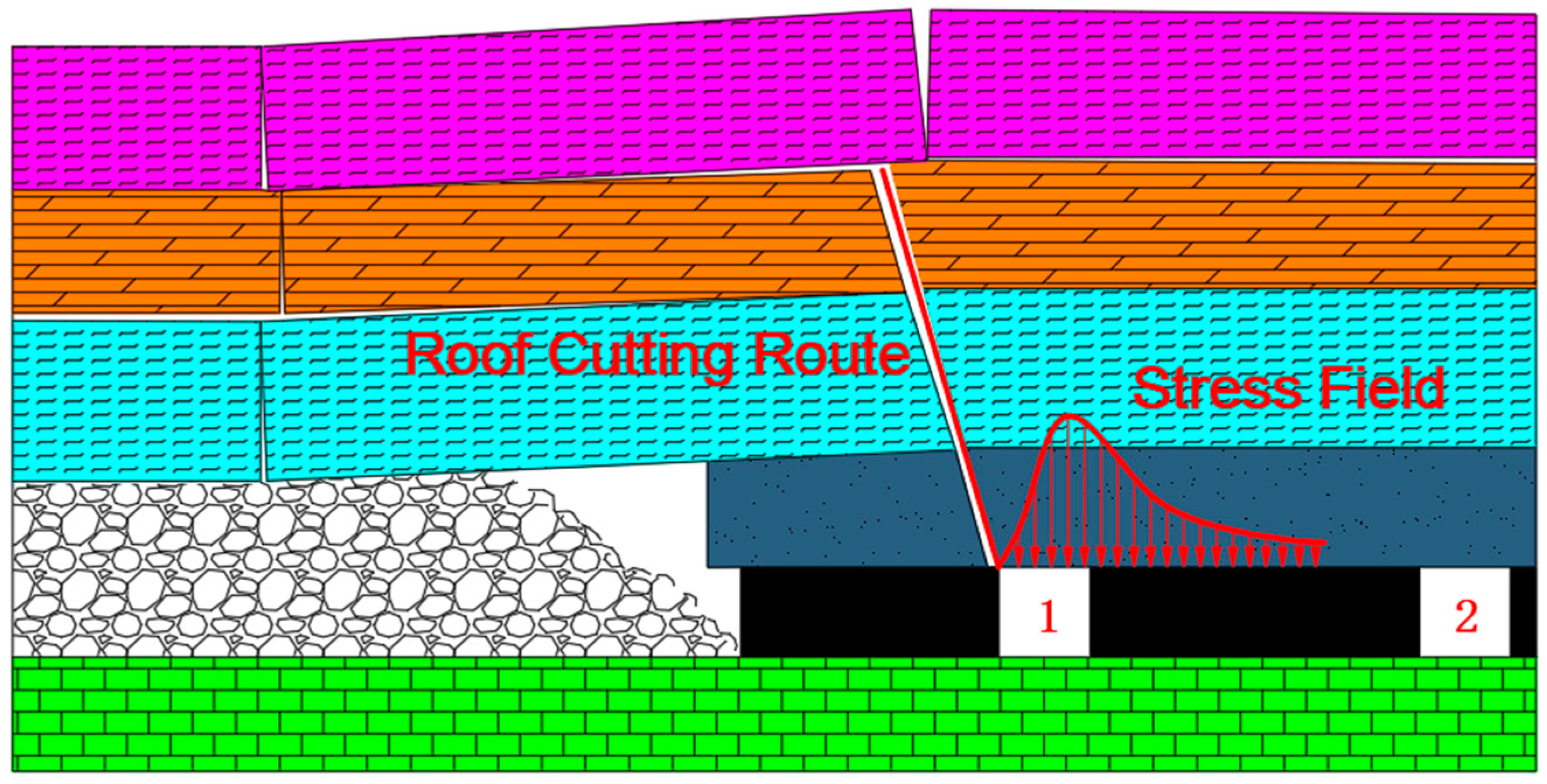
4. Cutting Top Analysis and Constant Resistance Anchor Cable Support

The main purpose of retreating the tunnel is to dismantle as well as withdraw the related equipment from the working face at the end of mining, so the rock steadiness of the roadway perimeter determines if the equipment in the working face can be dismantled smoothly, and it also influences the steadiness of the major tunnel, to a degree. In the course of coal mining, the pillar with the roadway is in the zone of elevated stress, which affects the stability of the roadway in the mining area. Directional roof cutting and pressure relief technology is mainly through the concentrated energy blasting device to achieve directional slit, and to cut the overlying rock beams on the retracted roadway to cut off the surrounding rock stress transfer path, in order to reduce the deformation of the roadway [34]. Then, according to the expansion characteristics of the rock, the critical arguments of the cutting of the top plate are being analyzed for optimization, so as to allow the cutting of the top plate to adequately fill the mining void area and perform the role of support.
As the retraction roadway is in the high stress area, due to the gradual enlargement of the area of the hollow zone, the rotary moment brought by the roof plate above the retraction roadway also gradually becomes larger, and the support strength required by the roadway also needs to be enhanced [35], as illustrated in Figure 7.
In order to change this state, we use blasting to cut the roof to turn the long roof plate above the roadway into a short roof plate, which can reduce the impact of the rotary moment [36,37], as illustrated in Figure 8.
The stress transfer structure of the roof rock can be changed by pre-cracking blasting. The stress transfer trail between the top plate of the retreating roadway and the top plate of the blast zone is cut off, so that the roadway is in the pressure-relief zone. It avoids the problem of highly concentrated stress in the coal columns and roadways in the mining area, and reduces the threat of high stress environments.

4.1. Determination of Important Parameters of the Cutting Top

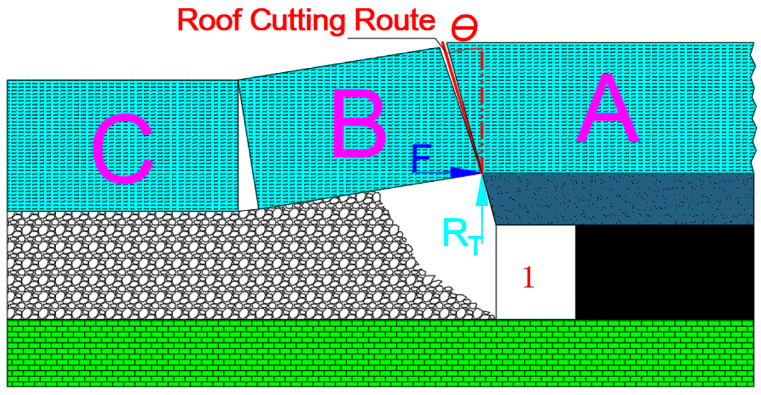
4.1.1. Theoretical Calculation of Top Cutting Pressure Relief Angle

From the mechanical model that can be introduced, cutting the top angle too large or too small will have an impact; if the angle is too small, rock friction is larger, which is not conducive to cut off the peripheral rock between the transfer of force; cutting the top angle too large will lead to cut off the length of the broken arm of the beam increases, resulting in the withdrawal of the roadway depressurization not being adequate [38].
According to the masonry beam theory, and the principle of structural stabilizing the perimeter rock structure, it can be seen that when the fracture surface of the basic top rock layer is considered to be at a certain angle θ to the vertical plane, the force relationship at the occlusion point of the rock block is shown in Figure 9.
And at this time, the conditions under which the rock block undergoes slip destabilization are
tan φ ( F cos θ R T sin θ ) R T cos θ + F sin θ
T = q L 2 2 d h
R T = q L
F is the horizontal thrust force on the rock mass ( k N ) ; RT is the shear force on the rock mass ( k N ); φ is the friction angle between the rock masses ( ° ); q is the load set of the basic top ( k N / m ); L is the length of the rock mass of the basic top, which is approximately equal to the cyclic come-pressure step ( m ); d is the thickness of the direct top, m; and ∆h is the subsidence of the rock mass B ( m ).
At θ = φ , no matter how large the force of the horizontal push F is, the structure of the rock mass will undergo slip instability. Therefore, when the cutting angle θ is equal to the friction angle φ between the rock blocks, the three-hinged arch rock block structure can not be balanced, and the basic top rock block can be smoothly cut down along the cut seam surface to form the lane gang, thus cutting off the path of lateral block to transmit force to the roof of the retaining lane to fully unloading the pressure and obtaining a good effect of forming the lane.
It is equivalent to reducing the lateral cantilever length of the roof plate, which is beneficial for maintenance along the empty stay lane, and the roof-cutting angle ought to be reduced as much as possible under the condition of satisfying that the basic top rock mass can collapse smoothly. Therefore, the top-cutting angle should be taken to satisfy the following equation.
θ = φ tan 1 2 d h L
From the geological conditions measured on site at the 108 working face of Jinjiitan Mine, we can obtain the friction angle of the salt block, φ = 22 ° ; the length of the basic top rock block, L = 18   m ; the sinking amount of the rock block B, h = 1.6   m ; and the thickness of the direct top, d = 2.8   m . It can be obtained that θ = 14.4 ° . Taking into account the convenience and error of the process of construction, after comprehensive deliberation, the angle of cutting the top is taken as 15°.

4.1.2. Theoretical Calculation of Top Cutting Relief Height

The critical design equation for the depth of the pre-cracked cut seam ( H s ) is as follows:
H s = H c H 1 H 2 K 1
H 1 : top plate subsidence, m; H 2 : bottom dropsy, m; K : coefficient of expansion, which takes 1.3~1.5; according to the field measurement, K takes 1.4; without considering the bottom dropsy, top plate subsidence, and only taking into account the influence of the mining height (taking the mining height as H c = 7.89   m ), then H s = 19.7   m , and we take the depth of pre-cracked slit hole as 20 m.

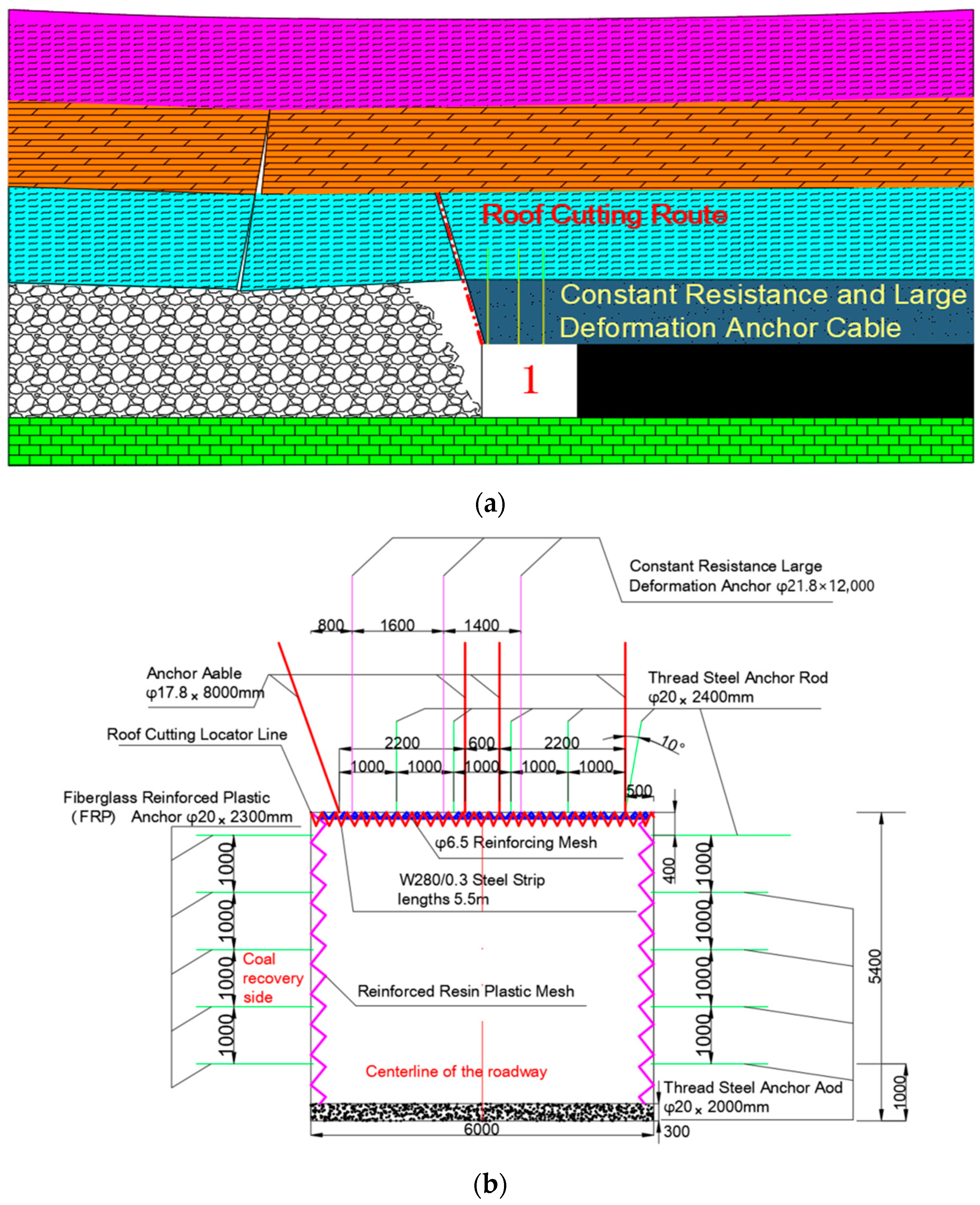
4.2. Bidirectional Energy-Cavity Blasting Technology

The tensile stress concentration in a set fracture direction is realized with the help of a two-way cohesive energy device, which uses the compressive but not tensile properties of the rock to fracture the rock mass [39,40]. Charging is carried out in controlled gunholes using a two-way polymerization device. After the explosive detonation, the shock wave and stress wave generated by the blast are preferentially released along the direction of the set polycondensation hole, acting on the hole wall in the corresponding direction of the polycondensation hole, forming a radial initial crack on the wall of the gunhole in the same direction as the polycondensation hole; subsequently, the explosive gas surges into the radial initial crack, generating a concentration of tensile stresses in the set direction to fracture the rock body, driving the cracks to expand along the set direction to form the rupture surface of the artificial structure, which can effectively cut off the connection of the overlying rock [41]. Thus, a smooth controlled blasting surface is formed to realize the purpose of cutting the top, as shown in Figure 10.

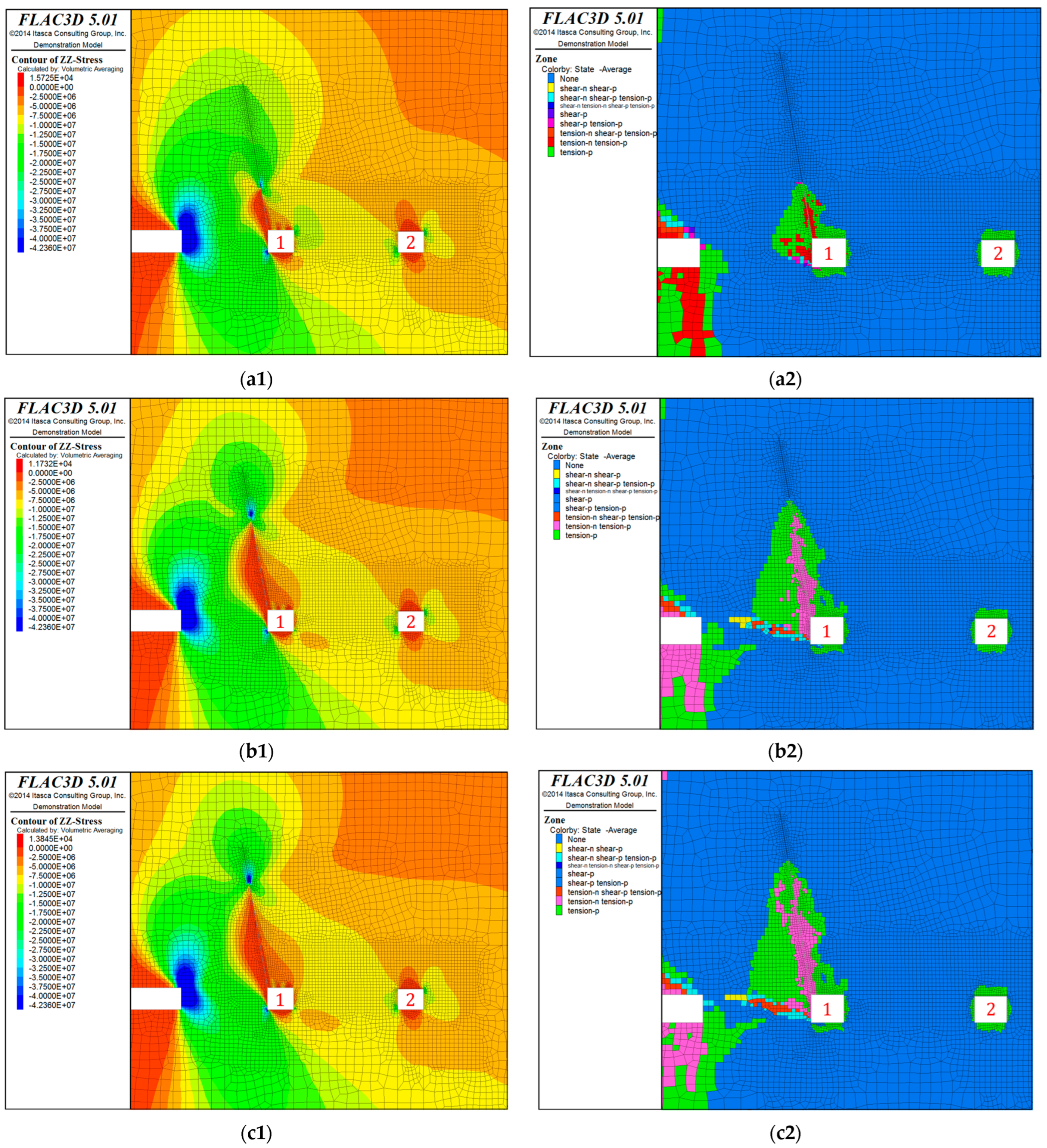
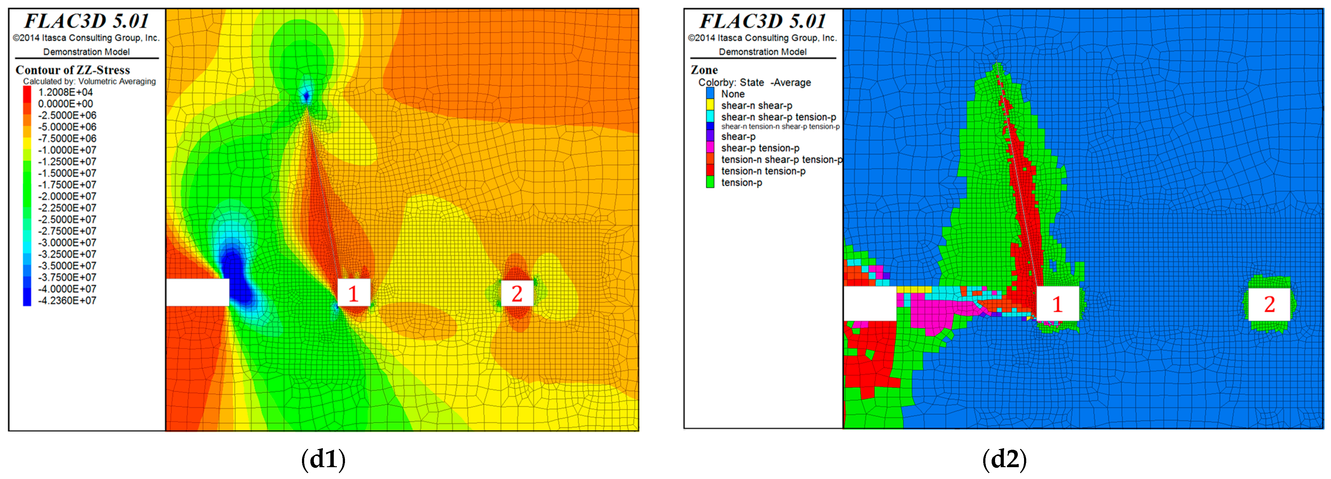
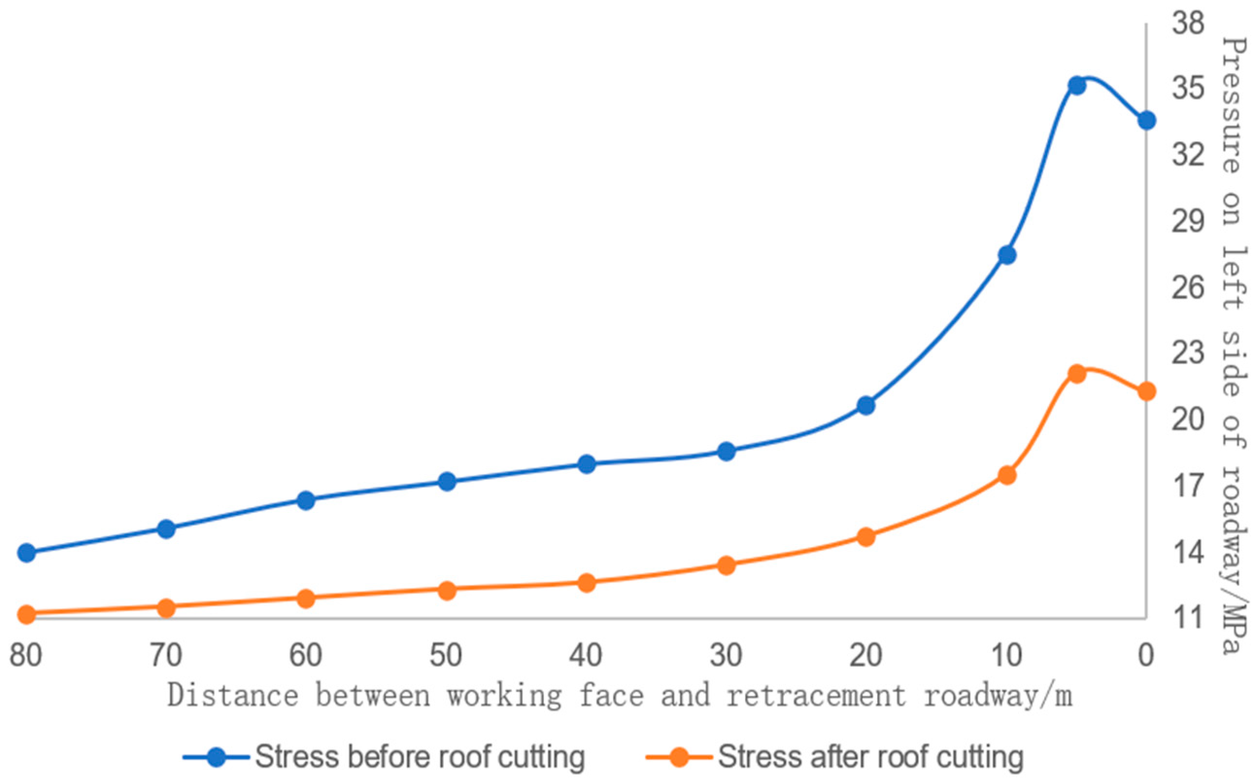
4.3. Roof Cutting Simulation Analysis

For a comparison of the effects of different top-cutting heights on the deformation of the roof plate and the stress distribution of the peripheral rock in the retreating roadway of the 108 mining face, a pre-mining simulation was carried out for the retreating of the coal mining face, and the vertical stress of the peripheral rock of the retreating roadway of the different top-cutting heights was comparatively analyzed under the condition that the angle of the top-cutting was 15°.
The outcome displays that while the cutting height is 13 m, 20 m, 23 m, and 34 m, respectively, as the height of the cutting height increases, the fracture high of key rock bridge increases, and stress in the surrounding rock near the main retreat channel gradually decreases, especially near the top of the main auxiliary channel, the stress in the surrounding sandstone is released, which is very conducive to the stabilization of the surrounding sandstone. Compared with the top-cutting height of 13 m, the surrounding rock stress is released more fully at a peak-cutting height of 20 m, and after the peak-cutting height is higher than 20 m, there is not much difference in the effect of top-cutting, but the distribution diagram of the plastic zone of the surrounding rock can be seen that when the peak-cutting height reaches 23 m, the distribution of the plastic zone of the surrounding rock is obviously increased, and the plastic zone of the roadway is through when the peak-cutting height reaches 34 m, which is unfavorable to the stability of the surrounding rock; thus, it is better to cut the peak-cutting height of 20 m. Therefore, the height of 20 m is relatively better, as shown in Figure 11.
Compared with the way without blasting and roof cutting, the surrounding rock’s main stress is minimized by using 20 m blasting to break the roof; the numerical calculation results show that after blasting and faulting, due to cutting off the transmission of the peripheral rock stress and changing the moments of the overlying rock beams, the peripheral rock stress near the main withdrawal channel will have a substantial reduction, especially near the top of the main withdrawal channel, the peripheral rock stress will be released, which is very conducive to the stability of the peripheral rock, and the peripheral rock stress near the roadway will decrease by 30~3%, which is the best solution for the stabilizes of the peripheral rock. The perimeter rock stress near the channel is reduced by 30~40%, as shown in Figure 12.
It can be seen, based on the cloud diagram of the change rule of roof pressure, that if the work faces farther away, as far as the retraction channel, working advancement does not have much influence on the force of the retraction channel; the work face advances from 60 m to 40 m from the retraction channel, and the surrounding rock between the retraction channel and the work face has a more obvious change in the force, with a force maxima located at 0~5 m ahead of the work, and a local maximal compressive stress on the roof plate of about 40 MPa; the work face advances to about 10 m from the retraction channel, and when it passes through, there is a localized compressive stress concentration at the top of the cut top, while the compressive stress near the roof plate decreases. At 10 m from the withdrawal channel, and when it is penetrated, a localized compressive stress concentration occurs at the top of the cut top, while the compressive stress near the top plate is reduced, as illustrated in Figure 13.

4.4. Stress Compensation Support of Constant Resistance and Large Deformation Anchor Cable

Drilling blasting roof cutting, on the one hand, increases the height of the roof caving in the goaf, compensates the space of the goaf, and provides strong support for the overlying rock beam; second, the long arm beam is transformed into a short arm beam, which cuts off the stress transfer of the surrounding rock [42].
As conventional support materials have defects, such as small prestress, low elongation, and weak energy-absorbing capacity, they cannot adequately compensate for the stress lost from the perimeter rock excavation, resulting in the disaster of large deformation of the perimeter rock [43]. Aiming at the characteristics of high prestress, fast pre-compression, high permanent resistivity, and large elongation of constant-resistance large deformation anchors to compensate for the stress of surrounding rock and control the expansion of fissures, it can provide high stress compensation to peripheral rock in a time and play a triaxial strength of the rock body [44]. The self-supporting ability of the deep surrounding rock is mobilized through the constant resistance large deformation ropes, forming a high-strength anchorage support structure, integrating self-supporting and large deformation ropes [45]. The layout of the reinforced retreat roadway support is illustrated in Figure 14.

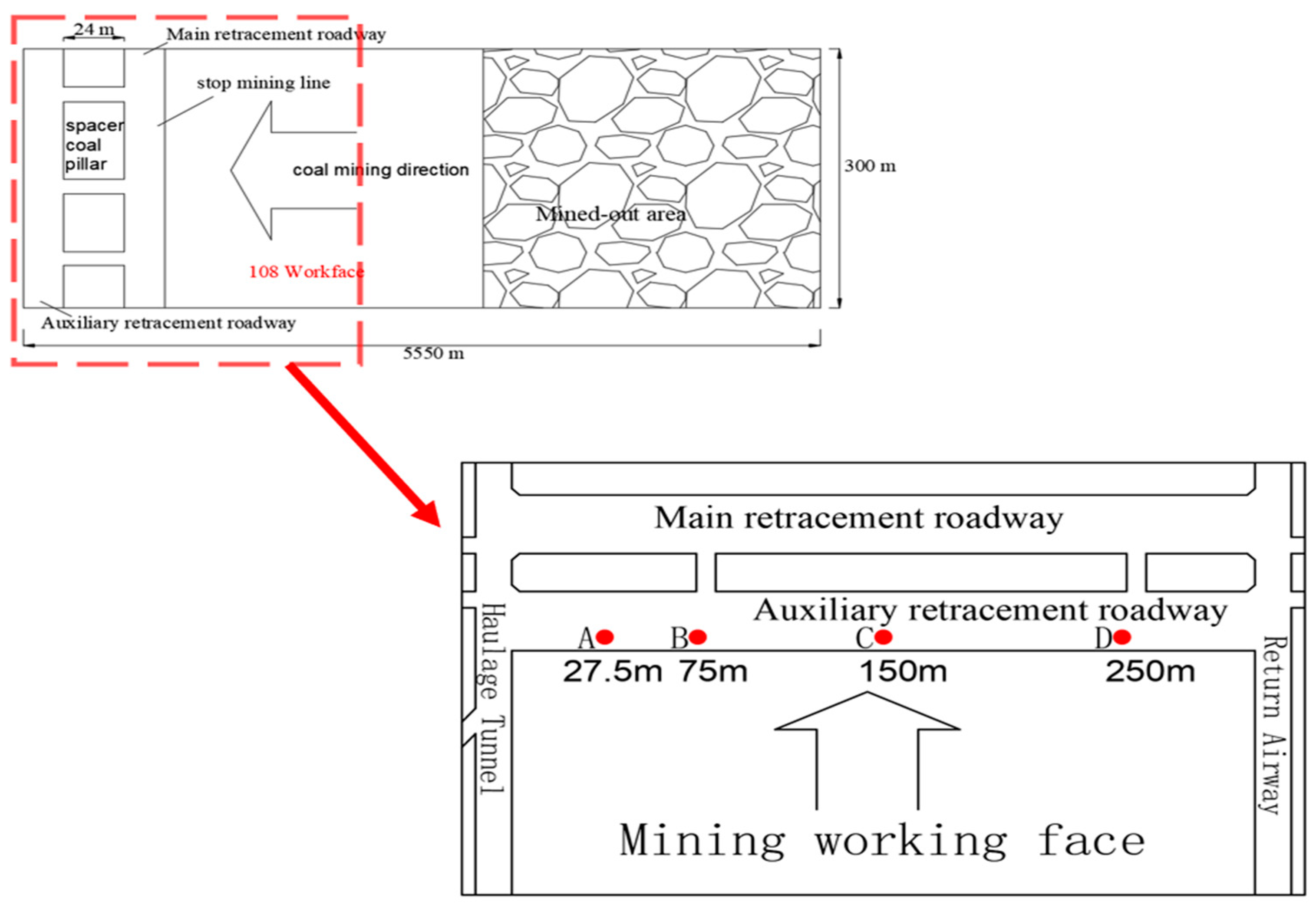
5. Monitoring Site Layout and Monitoring Analysis

When the mining moves away from the retreating roadway, the roadway is almost unaffected, and as the coal mining face continues to advance, the retreat roadway perimeter rock force gradually increased, and began to appear the phenomenon of destruction. [46,47]. In this regard, the field monitoring method is used to study the roadway breakage. True to the actual conditions on the line and the need for research, in the 108 working face of the main retreat roadway arranged four displacement monitoring points, as shown in Figure 15.
As the mining face progresses, the monitoring of roof displacement in the retreatment channel reveals a pattern: during the final phase of mining, the impact on the retreatment roadway intensifies as the coal face approaches to within 30 m. Notably, at the 20 m mark, the roof displacement of the retreatment roadway becomes significantly pronounced. However, the consistent resistance supplied by the constant resistance anchor cables helps to mitigate this. This resistance ensures that as the working face moves from 10 m away to directly above the roadway, the deformation reaches its peak and then begins to stabilize, as illustrated in Figure 16.
The analysis of the vertical stresses on the surrounding rock from the simulation results shows that when the coal mining face is about 25 m from the retracement roadway without cutting the top to unload the pressure, the surrounding rock stress starts to increase gradually; and when the distance is about 5 m, the peripheral rock stress has reached the largest about 35 MPa, and then due to the delay of the overlying cross-fall, the void of the working face fills in a certain supportive role, which makes the peripheral rock stress start to decline; compared to take the top-cutting measures, the maximum decline in the surrounding rock stress by 40%.

6. Conclusions

The superposition of the stress redistribution caused by the disturbance of the surrounding rock and the slewing moment of the upper roof plate seriously affects the stability of the retracement roadway. This study, through the retreat through the main key rock beams to break the roof blasting decompression method, and cut off the peripheral rock force chain of the transmission path at the same time, also reduces the rotation moment of the roof plate rock beams in the treadmill area, and the formation of the rock movement as the core, with constant resistance to large deformation of the anchor cable to absorb energy consumption energy support technology, to achieve the active control of the theoretical and technological changes in the prevention and mitigation of the disaster. We greatly diminish the problem of the old top of the oversized mining face with intense pressure, localized roofing and coal wall flake gangs difficult to support. This provides a reference for related works in other parts of the world.
(1) As the world’s first 8.2 m oversize mining face, this study reveals that the retreat channel is damaged by distortion under the joint action of stress and moment, and establishes safety control countermeasures for the peripheral rock in the retreat channel of oversize mining height. Through the calculation and simulation of the original support, it is concluded that it cannot bring guarantees to the safety of the tunnel. By cutting the top to remove the pressure and transforming the long roof plate to short roof plate, the slewing moment generated by the roof ridge of the roadway is reduced, and the peak value of the internal stress field is reduced.
(2) Combined with the numerical simulation results of FLAC3D, it is shown that when the top cutting is carried out by means of bidirectional energetic tensile blasting, when the height of the roof cut is 20 m, the surrounding rock stress of the retracted roadway is about 17~23 MPa. When the height of the top cutting continues to increase, the stress of the surrounding rock does not change much, but the distribution of the rock’s plastic zone increases, which is not conducive to the stabilization of the roadway.
(3) The hard top plate of the modified face is subjected to a 20 m roof excavation, which is then reinforced by a consistent set of high-deformation anchor cables to provide support and stress compensation for the roadway’s roof. This method has proven effective in maintaining structural integrity. Monitoring data indicate that using the combination of roof cutting and constant resistance high-deformation anchor cables, the maximum roof displacement is limited to 141 mm. The constant resistance offered by these cables, which can be sustained at approximately 162 kilonewtons, is instrumental in controlling the stability of the retreating tunnel, ensuring the safe, efficient, and swift extraction of oversized mining machinery.
(4) Due to engineering conditions and other reasons, the geological conditions of this study are relatively intact, and the address conditions of some soft rock with large deformation are not taken into account, and the focus will be placed on these special geological conditions in the future work.

Author Contributions

Methodology, L.P.; software, C.P.; validation, L.P. and W.L.; formal analysis, W.L.; investigation, L.P.; data curation, W.L.; writing—review and editing, W.L.; supervision, C.P.; project administration, L.P.; funding acquisition, L.P. All authors have read and agreed to the published version of the manuscript.

Funding

This research was funded by National Natural Science Foundation of China (Grant Number 51674058).

Institutional Review Board Statement

Not applicable.

Informed Consent Statement

Not applicable.

Data Availability Statement

The data presented in this study are available on request from the corresponding author. The data are not publicly available due to the confidentiality of the project involved.

Acknowledgments

We thank the anonymous reviewers for their constructive feedback.

Conflicts of Interest

The authors declare no conflicts of interest.

References

  1. Tao, Z.; Song, Z.; He, M.; Meng, Z.; Pang, S. Principles of the roof cut short-arm beam mining method (110 method) and its mining-induced stress distribution. Int. J. Min. Sci. Technol. 2018, 28, 391–396. [Google Scholar] [CrossRef]
  2. Sun, X.; He, M. Numerical Simulation Research on Coupling Support Theory of Roadway Within Soft Rock at Depth. J. China Univ. Min. Technol. 2005, 2, 37–40. [Google Scholar]
  3. Jiang, Z.; Jiang, B.; Zhang, C.; Ma, Y.; Wang, Y.; Li, D.; Wang, S. Research on cooperative control method of comprehensive pressure relief and anchor grouting reinforcement in deep mining roadways. Geomech. Geophys. Geo-Energy Geo-Resour. 2024, 10, 79. [Google Scholar] [CrossRef]
  4. Han, C.; Zhang, N.; Yang, H.; Zhao, Q.; Song, K. Discontinuous Deformation Characteristics of Deep Buried Roadway Roofs and Linkage Control of Thick Layer Cross-Boundary Anchorage: A Case Study. Energies 2023, 16, 2160. [Google Scholar] [CrossRef]
  5. Cui, J.; Wang, W.; Chao, Y. Application of stability analysis in surrounding rock control and support model of deep roadway. Int. J. Oil Gas Coal Technol. 2021, 29, 180–192. [Google Scholar] [CrossRef]
  6. Babets, D.; Babets, D.; Sdvyzhkova, O.; Hapieiev, S.; Shashenko, O.; Prykhodchenko, V. Multifactorial analysis of a gateroad stability at goaf interface during longwall coal mining—A case study. Min. Miner. Depos. 2023, 17, 9–19. [Google Scholar] [CrossRef]
  7. Pang, S. Design and Practical of Equipment remove Gateway of Fully Mechanized Coal Mining Working Face with Super Mining Height 8. 2 m. Coal Min. 2018, 4, 45–49. [Google Scholar]
  8. Rabcewicz, L. The new Austrian tunnelling method. Water Power 1964, 11, 453–457. [Google Scholar]
  9. Hou, C.; Wang, X.; Bai, J.; Meng, N.; Wu, W. Basic theory and technology study of stability control for surrounding rock in deep roadway. J. China Univ. Min. Technol. 2021, 1, 1–12. [Google Scholar]
  10. Liu, X.; Hua, X.; Liang, Y.; Li, C. Quantitative Research on Roof Deformation and Temporary Support Stiffness in Deep-Mine Gob-Side Entry Retaining by Roof Cutting. Appl. Sci 2024, 14, 6520. [Google Scholar] [CrossRef]
  11. Yue, X.; Tu, M.; Li, Y.; Chang, G.; Li, C. Stability and cementation of the surrounding rock in roof-cutting and pressure-relief entry under mining influence. Energies 2022, 13, 951. [Google Scholar] [CrossRef]
  12. Xue, H.; Wang, Q.; Jiang, B.; Jiang, Z.; Wang, Y.; Huang, Y.; He, M. Study on the method of pressure relief by roof cutting and absorbing energy in deep coal mines. Bull. Eng. Geol. Environ. 2023, 82, 298. [Google Scholar] [CrossRef]
  13. Xiong, J.; Yang, T.; Yang, Y. Key parameters of roof cutting along the dip in withdrawing face. Coal Eng. 2023, 8, 68–72. [Google Scholar]
  14. He, C.; Xu, X.; Yang, J.; Ding, W.; Wang, Z.; Wang, Y.; Chen, F. Surrounding rock deformation control for roof cutting and pressure relief under thick and hard roof. Coal Eng. 2022, 9, 59–63. [Google Scholar]
  15. Guo, J.; Li, Y.; Shi, S.; Jiang, Y.; Cheng, D.; He, F.; Xie, S. Self-forming roadway of roof cutting and surrounding rock control technology under thick and hard basic roof. J. China Coal Soc. 2021, 46, 2853–2864. [Google Scholar]
  16. Wang, J.; Zhu, D.; Gong, W.; He, M.; Gao, R. Physical simulation experiment on the movement of rock strata upon automatic roadway forming by roof cutting and pressure releasing. Chin. J. Rock Mech. Eng. 2018, 11, 2536–2547. [Google Scholar]
  17. Li, Z.; Tao, Z.; Meng, Z.; He, M. Longwall mining method with roof-cutting unloading and numerical investigation of ground pressure and roof stability. Arab.J. Geosci. 2018, 11, 697. [Google Scholar] [CrossRef]
  18. Wang, Q.; Zhang, P.; Jiang, Z.; He, M.; Li, S.; Wang, Y.; Jiang, B. Automatic roadway formation method by roof cutting with high strength bolt-grouting in deep coal mine and its validation. Coal J. 2021, 2, 382–397. [Google Scholar]
  19. Wang, Q.; Liu, J.; Jiang, B.; Xue, H.; Gao, H.; Jiang, Z. Research on control methods of automatically-formed roadway without coal pillar for extremely close-distance coal seams. J. Min. Strat. Control Eng. 2024, 1, 22–37. [Google Scholar]
  20. Liu, X.; Hua, X.; Yang, P.; Huang, Z. A study of the mechanical structure of the direct roof during the whole process of non-pillar gob-side entry retaining by roof cutting. Energy Explor. Exploit. 2020, 38, 1706–1724. [Google Scholar] [CrossRef]
  21. Guo, Z.; Li, W.; He, M.; Tang, J. Failure mechanisms and control strategies in dynamic pressure roadways of deep soft rock based on compensation theory. J. China Univ. Min. Technol. 2023, 5, 931–942. [Google Scholar]
  22. Hou, G.; Hu, T.; Li, Z.; Li, Z.; Cheng, J.; Cui, Y. Effect of cutting roof height on the stability of gob-side retaining roadway with roadside support. J. Min. Saf. Eng. 2019, 36, 925–931. [Google Scholar]
  23. He, M.; Ma, Z.; Guo, Z.; Chen, S. Key parameters of the gob-side entry retaining formed by roocutting and pressure release in deep medium thickness coal seams. J. China Univ. Min. Technol. 2018, 3, 468–477. [Google Scholar]
  24. Liu, H.; Zhao, Y.; Ren, T.; Wang, F.; Li, Z. Characteristics of overburden failure and fracture developmentin gob of mining with gob side entry formed by cutting roof. J. China Univ. Min. Technol. 2022, 1, 77–89. [Google Scholar]
  25. Wang, Y. Parameter design and engineering application of directional blasting for roof cutting pressure relief of waterproof coal pilla. Coal Eng. 2024, 2, 1–9. [Google Scholar]
  26. Bednarek, Ł.; Małkowski, P.; Niedbalski, Z.; Mucha, K. Steel Arch and Rock Bolt Support in Terms of the Gateroad Stability Maintaining behind the Longwall Face. Appl. Sci 2024, 14, 3594. [Google Scholar] [CrossRef]
  27. Chen, S.; Zhao, F.; Wang, H.; Yuan, G.; Guo, Z.; Yang, J. Determination of key parameters of gob-side entry retaining by cutting roof and its application to a deep mine. Rock Soil Mech. 2019, 1, 332–342+350. [Google Scholar]
  28. Yang, X.; Liu, C.; Ji, Y.; Ji, Y.; Zhang, X.; Wang, S. Research on Roof Cutting and Pressure Releasing Technology of Directional Fracture Blasting in Dynamic Pressure Roadway. Geotech. Geol. Eng. 2019, 37, 1555–1567. [Google Scholar] [CrossRef]
  29. Vu, T. Solutions to prevent face spall and roof falling in fully mechanized longwall at underground mines. Min. Miner. Depos. 2022, 16, 127–134. [Google Scholar] [CrossRef]
  30. Cheng, J.; Wei, Z.; Bai, J.; Yu, Z.; Xing, K.; Li, Q.; Wang, Y.; Li, X.; Zhang, Z.; Zhang, Z. Study on floor heave control technology of deep tectonic stress water-rich soft rock roadway based on blasting pressure relief. Coal Sci. Technol. 2022, 50, 117–126. [Google Scholar]
  31. Peng, L.; Yue, N.; An, L.; Li, S.; Cai, F.; Feng, Z.; Li, M. Study on support of retractable channel in fully-mechanized miningface with super large mining height. Coal Sci. Technol. 2022, 6, 204–210. [Google Scholar]
  32. Xie, S.; Wu, Y.; Guo, F.; Zou, H.; Chen, D.; Zhang, X.; Ma, X.; Liu, R.; Wu, C. Application of pre-Splitting and roof-cutting control technology in coal mining: A review of technology. Energies 2022, 15, 6489. [Google Scholar] [CrossRef]
  33. Zhu, Q.; Xue, F.; Bai, G.; Li, T.; Wang, B.; Zhao, J. An exploration of improving the stability of mining roadways constructed in soft rock by roof cutting and stress transfer: A case study. Eng. Fail. Anal. 2024, 157, 107898. [Google Scholar] [CrossRef]
  34. Gao, Y.; Yang, J.; Zhang, X.; Xue, H.; He, M. Study on surrounding rock control of roadways in deep coal mines based on roof cutting and pressure release technology by directional tensile blasting. Chin. J. Rock Mech. Eng. 2019, 38, 2045–2056. [Google Scholar]
  35. Yang, Y. Research on the Support Technology of CompositeRoof Retraction Passage with Ooze Invasionin Multi-hole Karst Area. Master’s Thesis, Taiyuan University of Technology, Taiyuan, China, 2020. [Google Scholar]
  36. Yang, J.; Wei, Q.; Wang, Y.; Gao, Y.; Hou, S.; Qiao, B. Roof deformation mechanism and control measures of pillarless mining with gob-side entry retaining by roof cutting and pressure relief. Rock Soil Mech. 2020, 41, 989–998. [Google Scholar]
  37. He, M.; Song, Z.; Wang, A.; Yang, H.; Qi, H.; Guo, Z. Theory of longwall mining by using roof cuting shortwall team and 110 method—The third mining science and technology reform. Coal Technol. 2017, 1, 1–9+13. [Google Scholar]
  38. Han, Z.; Huang, Y.; Li, J.; Zayzay, S., Jr.; Guo, H. Study on key parameters of roof cutting and pressure release in medium-thickness coal seam. Geotech. Geol. Eng. 2019, 12, 3413–3422. [Google Scholar] [CrossRef]
  39. Liu, S. Research and application of bidirectional shaped tensile forming blasting technology. Shandong Coal Sci. Technol. 2013, 4, 175–177. [Google Scholar]
  40. Cho, S.; Nakamura, Y.; Mohanty, B.; Yang, H.; Kaneko, K. Numerical study of fracture plane control in laboratory-scale blasting. Eng. Fract. Mech. 2008, 75, 3966–3984. [Google Scholar] [CrossRef]
  41. Zhang, X.; Hu, J.; Xue, H.; Mao, W.; Gao, Y.; Yang, J.; He, M. Innovative approach based on roof cutting by energy-gathering blasting for protecting roadways in coal mines. Tunn. Undergr. Space Technol. 2020, 99, 103387. [Google Scholar] [CrossRef]
  42. Liu, J.; Li, D.; Chen, X.; Wang, S.; Wang, H.; Xu, Y. Overburden stress arch elevation effect induced by roof cutting and destress technique in coal mine longwall panel and its control mechanism to entry surrounding rock. Min. Metall. Explor. 2023, 40, 1237–1252. [Google Scholar] [CrossRef]
  43. Chen, S.; Zhao, B.; Zhao, F.; Yuan, G.; Wang, H.; Wang, X.; Guo, Z. Mechanical characteristics of constant resistance and large deformation anchor cable and its application in deep gob-side entry retaining by roof cutting. Coal Eng. 2020, 11, 103–107. [Google Scholar]
  44. Wang, J.; Liu, P.; He, M.; Tian, H.; Gong, W. Mechanical Behaviour of a Deep Soft Rock Large Deformation Roadway Supported by NPR Bolts: A Case Study. Rock Mech. Rock Eng. 2023, 56, 8851–8867. [Google Scholar] [CrossRef]
  45. Wang, Q.; Jiang, Z.; Jiang, B.; Gao, H.; Huang, Y.; Zhang, P. Research on an automatic roadway formation method in deep mining areas by roof cutting with high-strength bolt-grouting. Int. J. Rock Mech. Min. Sci. 2020, 128, 104264. [Google Scholar] [CrossRef]
  46. Lv, K.; Zhao, Z.; Zhao, Z. Study on support technology of equipment removal channel in fully-mechanized top coal caving face in ultra—Thick seam. Coal Sci. Technol. 2018, 3, 39–43. [Google Scholar]
  47. Jing, H.; Wu, J.; Yin, Q.; Wang, K. Deformation and failure characteristics of anchorage structure of surrounding rock in deep roadway. Int. J. Min. Sci. Technol. 2020, 5, 593–604. [Google Scholar] [CrossRef]
Figure 1. Information on the geographic location of the mine and the top view of the working face. (a) Schematic location of the coal mine; (b) 108 top view of the mining face.
Applsci 14 07946 g001
Figure 2. Borehole histogram.
Applsci 14 07946 g002
Figure 3. Original supporting structure.
Applsci 14 07946 g003
Figure 4. Model schematic and boundaries length.
Applsci 14 07946 g004
Figure 5. Enclosed rock force cloud map (a) Surrounding rock stress when the working face is 200 m away from the main retreat roadway; (b) surrounding rock stress when the working face is 40 m away from the main retreat roadway.
Applsci 14 07946 g005
Figure 6. Enclosed rock force cloud map. (a) Force cloud diagram of anchor bolt; (b) force cloud diagram of an anchor cable.
Applsci 14 07946 g006
Figure 7. Distribution of stress field before roof cutting. 1: main retracement roadway; 2: auxiliary retracement roadway.
Applsci 14 07946 g007
Figure 8. Stress field distribution after roof cutting. 1: main retracement roadway; 2: auxiliary retracement roadway.
Applsci 14 07946 g008
Figure 9. Modeling of the upper roof plate force after cutting the roof and unloading the pressure; 1: main retracement roadway. A: Coal wall support impact zone; B: transition zone where rocks are dropped; C: collapse and compaction zone.
Applsci 14 07946 g009
Figure 10. Schematic diagram of blasting and roof cutting. (a) Schematic diagram of two-way energy cavity blasting technology; (b) two-way energy blasting on-site cutting roof effect.
Applsci 14 07946 g010
Figure 11. Distribution of stresses and plastic zones at different depths of roof cutting. (a1) Stress map of the surrounding rock at 13 m of roof cutting; (a2) plastic zone cloud map of the surrounding rock at 13 m after cutting the roof; (b1) stress map of the surrounding rock at 20 m of roof cutting; (b2) plastic zone cloud map of the surrounding rock at 20 m after cutting the roof; (c1) stress map of the surrounding rock at 23 m of roof cutting; (c2) plastic zone cloud map of the surrounding rock at 23 m after cutting the roof; (d1) stress map of the surrounding rock at 32 m of roof cutting; (d2) plastic zone cloud map of the surrounding rock at 32 m after cutting the roof. 1: main retracement roadway; 2: auxiliary retracement roadway.
Applsci 14 07946 g011aApplsci 14 07946 g011b
Figure 12. Comparison of stress clouds with and without the implementation of roof cutting. (a) No roof cutting was performed (Figure 4); (b) carrying out the roof cutting.
Applsci 14 07946 g012
Figure 13. Comparison of stress before and after roof cutting at different distances.
Applsci 14 07946 g013
Figure 14. (a) Schematic diagram of constant resistance large deformation anchor cable arrangement 1: main retracement roadway; (b) layout of the reinforced roadway supports.
Applsci 14 07946 g014
Figure 15. Schematic diagram of constant resistance monitoring station layout diagram. A; B; C; D are 4 monitoring stations.
Applsci 14 07946 g015
Figure 16. Monitoring data for roadway roof displacement and constant resistance anchors. (a) Changes in roof displacement in the retraction roadway; (b) change in force on constant resistance anchors.
Applsci 14 07946 g016
Table 1. Mechanical properties of rocks.
LithologyDensities/kg/m3Elastic Modulus/GPaTensile Strength/MPaCohesion
/MPa
Angle of Internal Friction
Medium sandstone265312.54.62.531
Mudstone25898.672.551.725
Coarse Sandstone281312.356.52.720
Siltstone268016.56.971.321
Coal seam13901.681.11.219
Thickness253114.66.582.032
Disclaimer/Publisher’s Note: The statements, opinions and data contained in all publications are solely those of the individual author(s) and contributor(s) and not of MDPI and/or the editor(s). MDPI and/or the editor(s) disclaim responsibility for any injury to people or property resulting from any ideas, methods, instructions or products referred to in the content.

