
Venus Magnetotail Long-Term Sensing Using Solar Sails


Department of Civil and Industrial Engineering, University of Pisa, I-56122 Pisa, Italy
Appl. Sci. 2024, 14(17), 8016; https://doi.org/10.3390/app14178016 (registering DOI)
Submission received: 25 July 2024
/
Revised: 3 September 2024
/
Accepted: 5 September 2024
/
Published: 7 September 2024
(This article belongs to the Section Aerospace Science and Engineering)
Abstract
:Propellantless propulsion systems, such as the well-known photonic solar sails that provide thrust by exploiting the solar radiation pressure, theoretically allow for extremely complex space missions that require a high value of velocity variation to be carried out. Such challenging space missions typically need the application of continuous thrust for a very long period of time, compared to the classic operational life of a space vehicle equipped with a more conventional propulsion system as, for example, an electric thruster. In this context, an interesting application of this propellantless thruster consists of using the solar sail-induced acceleration to artificially precess the apse line of a planetocentric elliptic orbit. This specific mission application was thoroughly investigated about twenty years ago in the context of the GeoSail Technology Reference Study, which analyzed the potential use of a spacecraft equipped with a small solar sail to perform an in situ study of the Earth’s upper magnetosphere. Taking inspiration from the GeoSail concept, this study analyzes the performance of a solar sail-based spacecraft in (artificially) precessing the apse line of a high elliptic orbit around Venus with the aim of exploring the planet’s induced magnetotail. In particular, during flight, the solar sail orientation is assumed to be Sun-facing, and the required thruster’s performance is evaluated as a function of the elliptic orbit’s characteristics by using both a simplified mathematical model of the spacecraft’s planetocentric dynamics and an approximate analytical approach. Numerical results show that a medium–low-performance sail is able to artificially precess the apse line of a Venus-centered orbit in order to ensure the long-term sensing of the planet’s induced magnetotail.
1. Introduction
Since the pioneering Soviet missions of the Venera family, which were the first to successfully enter the atmosphere of Venus and make a soft landing on the planet, or NASA’s missions such as the Mariner 2 launched in the early 1960s and the Pioneer Venus Orbiter launched in the late 1970s [1], and more recently, thanks to the ESA’s Venus Express mission and the ESA/JAXA’s BepiColombo, which is currently on an interplanetary flight to its target planet, the exploration of Venus’s induced magnetosphere and the related magnetotail has provided useful data to better understand the complex Sun–Venus connection, and how the solar wind interacts with the upper atmosphere of the second Solar System’s planet [2,3]. In fact, the particular physical origin of Venus’s magnetic field [4], which originates from the interaction of the solar wind stream of charged particles with the ionized atoms that populate the planet’s upper atmosphere, differentiates Venus’s magnetotail from that of magnetized planets as, for example, the Earth [5]. In this context, the artistic impression in Figure 1 schematically describes the differences between the induced magnetosphere of Venus (and Mars) and that of the Earth.
Over the decades, Venus has been the study object (or a flyby planet on its way to the final target) of several interplanetary spacecraft. For example, NASA’s Pioneer Venus Orbiter observed the central region of Venus’s magnetotail at a distance between and [6], where is Venus’s mean radius, while the ESA’s Venus Express observed a downstream region of the magnetosphere at a distance of roughly , due to the high orbital inclination of that space probe with respect to the equatorial plane of the planet [7,8]. Figure 2 shows an artistic impression of the Venus Express spacecraft approaching the planet on its successful science mission, which ended in early 2015. More recently (i.e., in October 2020 and August 2021), the two Venus flybys of the ESA-JAXA’s BepiColombo spacecraft provided new and interesting data regarding both the physical composition of the planet’s upper atmosphere and the structure of its induced magnetosphere [9,10].
To date, however, a systematic and in situ exploration of Venus’s comet-like induced magnetotail has not been performed. In fact, a continued and long-term probing of the physical characteristics of the trailing part of a magnetosphere usually requires a continuous-thrust propulsion system, which is able to change the orientation of a suitable elliptic (planetocentric) orbit whose apocytherion lies inside the planet’s magnetotail. Consequently, the continuous and prolonged application of propulsive acceleration indicates that this type of mission requires a considerable velocity change, which, in turn, makes them difficult to achieve using a conventional thruster whose capabilities are constrained by the mass of storable propellant on board.
A possible solution, in this respect, is offered by a propellantless propulsion system. In fact, propellantless thrusters, such as the well-known photonic solar sails [11,12,13], the exotic Magnetic Sails proposed by Zubrin and Andrews in the early 1990s [14,15], the more recent Electric Solar Wind Sails invented by Janhunen in 2004 [16,17,18], or the advanced Solar Wind Ion Focusing Thrusters (SWIFTs) recently proposed by Gemmer et al. [19,20,21], theoretically allow for extremely complex space missions that require a very high value in terms of the velocity change [22,23]. In this specific case, keeping in mind that the spacecraft flies (and, therefore, the propellantless thruster operates) inside the planet’s magnetosphere, the only possible option among those just indicated consists of the use of a photonic solar sail [24].
For this reason, the use of a small (reflective) solar sail as the primary propulsion system was proposed roughly 20 years ago during the preliminary design of the GeoSail mission concept [25], the aim of which was to create a geocentric orbit capable of enabling the in situ sensing of the Earth’s upper magnetosphere. To this end, it was proposed to use the propulsive acceleration induced by the reflective solar sail to achieve an artificial precession of the apsidal line of an assigned (elliptic) geocentric orbit, so as to maintain the apogee within the Earth’s magnetotail over time. In this context, thanks to the pioneering studies of McInnes et al. [26], it was demonstrated that such artificial precession could be achieved using a low-performance reflective solar sail with a substantially constant attitude with respect to the direction of propagation of the solar rays [27,28]. This interesting result was then subsequently refined by the author using an optimized guidance law [29,30] or a suitable on/off control strategy [31], which allows the mission concept to be extended to smart dust with an electrochromic control device. More recently, as a valid alternative to the classical reflective sails, solar sails with advanced metamaterial films have been proposed. This is, for example, the case of the so-called refractive sails [32,33,34], or the interesting diffractive sails whose performance has been thoroughly investigated by Swartzlander et al. [35,36,37,38]. The interesting aspect of a diffractive or a refractive sail is the possibility of generating a transverse component of the propulsive acceleration even with a Sun-facing orientation, that is, an orientation in which the direction of the solar rays is perpendicular to the nominal plane of the thin sail membrane [39,40]. Such a Sun-facing attitude can be maintained passively through a suitable design of the sail’s external structure, i.e., by providing a slightly conical form with the apex directed to the Sun [41].
Taking inspiration from the GeoSail concept, and leaving the study of the performance of diffractive or refractive sails to future works, this study analyzes the performance of a reflective solar sail-based spacecraft in (artificially) precessing the apse line of a high-elliptic orbit around Venus with the aim of exploring the planet’s induced magnetotail. In particular, the solar sail-induced propulsive acceleration vector allows a scientific probe to obtain long-term residence within the induced magnetotail of the planet. The mission concept is schematized in Figure 3, which shows how the apse line of the spacecraft’s planetocentric orbit remains substantially aligned with the Sun–Venus direction during the flight. In particular, Figure 3 indicates that the plane of the spacecraft’s science (planetocentric) orbit coincides with the plane of the heliocentric orbit of Venus. Bearing in mind that the axial tilt of Venus is roughly , one can infer that substantially coincides with the equatorial plane of the planet. Note that, in Figure 3, the orbit of Venus around the Sun is assumed to be circular with a radius so that the planet moves in its heliocentric orbit with a constant angular velocity equal to , where is the Sun’s gravitational parameter.
In this study, the orientation of the reflective solar sail with respect to a classical orbital reference frame is assumed to be fixed. In particular, a Sun-facing configuration is assumed, while the required propulsion system’s performance is evaluated as a function of the characteristics of the elliptic science orbit, that is, the value of the pericytherion radius and the apocytherion radius [42,43]. In this context, as discussed in detail in Section 2, the required thruster performance parameters (in terms of the value of the reference, characteristic, and propulsive acceleration magnitude) are obtained by using both a simplified mathematical model of the spacecraft’s planetocentric dynamics and a semi-analytical approach, which allows the reference propulsive acceleration to be easily written, in a closed compact form, as a function of and . The numerical results illustrated in Section 3 show that a medium–low-performance sail is able to artificially precess the apse line of a medium–high-elliptic orbit around Venus, in order to ensure the long-term sensing of the planet’s induced magnetotail. The performance analysis in Section 3 is conducted parametrically using the two geometric terms as design parameters, while a set of curves is obtained to quickly determine the required value of the sail-induced (reference) propulsive acceleration magnitude. The last part of Section 3 briefly describes the analysis of the effects of the eclipse period on the mission performance, by using a simplified (cylindrical) model of the Venus-induced shadow. Finally, as usual, the last section includes the conclusions of this study.
2. Mission Description and Simplified Mathematical Model
In this section, the dynamics of the solar sail-based spacecraft in its motion around Venus are described using the simplified approach proposed by McInnes et al. [26]. More precisely, assuming a two-dimensional scenario in which the spacecraft and Venus move around the Sun along the same plane introduced in the previous section, the solar sail dynamics along the planetocentric, elliptic, science orbit is described by the following four simplified Lagrange planetary equations (in Gaussian form) [44]:
which are consistent with the set of equations used in Ref. [31], where is Venus’s gravitational parameter, while
In particular, Equations (1)–(4) give the variation with the true anomaly of the spacecraft’s osculating orbit semimajor axis , eccentricity , time of passage from the pericytherion, and argument of pericytherion . The latter is measured counterclockwise from a fixed direction, which coincides with the Venus–Sun line at the initial time . In Equations (1)–(4), the term r is the Venus–spacecraft distance, while (or ) is the radial (or transverse) component of the solar sail-induced propulsive acceleration vector . In particular, the radial component of vector is directed along the Venus–spacecraft line, while the transverse component is positive when , where is the spacecraft’s velocity vector in its motion around Venus.
The four first-order differential Equations (1)–(4) are completed by four initial conditions, that is, four scalar conditions at the initial true anomaly . In this context, without losing generality, we assume that, initially, the science orbit apse line is aligned with the Venus–Sun direction, so that the initial value of is zero; this situation is illustrated in Figure 4, where the pericytherion radius , the apocytherion radius , and the mean radius of Venus are indicated. Accordingly, the four initial conditions are as follows:
The spacecraft equations of motion and the initial conditions given by the previous equation are more conveniently rewritten in a dimensionless form by introducing the following (dimensionless) terms:
with
In the remainder of the paper, the dimensionless version of a generic variable will be indicated with the tilde superscript.
According to Equation (7), the dimensionless version of the spacecraft’s equations of motion is as follows:
while the initial conditions given by Equation (6) become
2.1. Solar Sail Thrust Components with Sun-Facing Orientation
To complete the Cauchy problem given by Equations (9)–(13), it is necessary to assign the control law that provides the variation with the true anomaly of the two components of the dimensionless propulsive acceleration vector given by the solar sail. In this respect, taking into account the numerical results of Ref. [26], we consider a fixed orientation of the solar sail nominal plane (i.e., the plane of the thin reflective membrane when sail billowing is neglected) with respect to the Sun–spacecraft line during the entire flight along the science orbit. In this context, paralleling the procedure described in Ref. [31], we assume that the solar sail’s orientation is Sun-facing, that is, the sail nominal plane is perpendicular to the Sun–spacecraft line at any time instant [26]. This situation is schematized in Figure 5, which also shows the two dimensionless components (i.e., the radial and transverse components) of the propulsive acceleration vector in a generic point of the spacecraft’s science orbit.
In this case, bearing in mind that during the flight, the Sun–spacecraft distance is substantially constant and equal to , neglecting the eclipse period experienced during the flight, and observing that the direction of the sun rays is parallel to the science orbit apse line (recall that the Sun belongs to that line; see the scheme in Figure 4), one has the following expressions of the two components :
where is a reference distance that coincides with the Sun–Earth mean distance, and is the dimensionless version of the sail characteristic acceleration , which is the typical performance parameter in the trajectory design of a solar sail-based space vehicle when the optical degradation of the reflective film is neglected [45]. Note that Equations (14) and (15) indicate the effect of the solar radiation pressure (i.e., the thrust vector induced by the solar sail) on the motion of the spacecraft around the planet, according to the typical results in the literature. In particular, recall that is defined [46,47] as the maximum value of the magnitude of the solar sail-induced propulsive acceleration vector when the distance from the Sun is equal to . Note that, given the same sail design characteristics (as, for example, the sail area, the mass breakdown, and the reflective film performance), the use of a solar sail propulsion system in a Venus-centered mission scenario allows for an increase of the maximum magnitude of the propulsive acceleration vector compared to the case of an Earth-centered application. However, in a Venus-centered scenario, the solar sail must be able to rotate the science orbit apse line faster than in a classical Earth-centered scenario. In fact, in a Venus case, the apse line should be rotated about to maintain the apocytherion inside the planet’s induced magnetotail (recall that the orbital period of Venus is roughly , so ), while in a geocentric case, the required rotation rate is slightly less than .
The effects on the spacecraft’s planetocentric dynamics of the simplified control law given by Equations (14) and (15), which are shown in Figure 6, have been accurately studied in Ref. [26]. In particular, McInnes et al. [26] indicated that the simple control law (14) and (15) allowed the authors to obtain an averaged value equal to zero regarding both the semimajor axis and the eccentricity over a complete revolution of the spacecraft around the planet. This result can be easily obtained by substituting Equations (8), (14), and (15) into Equations (9) and (10) and observing that and are odd functions of the true anomaly. On the other hand, that proposed control law gives a non-zero net variation (over a single revolution around the planet) considering the argument of pericytherion . Therefore, this specific characteristic of the simple control law given by Equations (14) and (15) can be used to obtain a (target) value of , which allows the science orbit apse line to be aligned again with the Venus–spacecraft direction at the end of the generic revolution around the planet.
Bearing in mind that the initial value of is zero and observing that the azimuthal angle traveled by Venus’s center of mass along its heliocentric (circular) orbit in a time interval is simply , the following final condition is derived at the true anomaly :
where is the time instant at the end of the spacecraft revolution around the planet, and Equation (7) is used to express the dimensionless version of the flight time. In fact, recall that the final values of both and e, i.e., the values at the end of the revolution around the planet, correspond to their initial value [26]. In other terms, for a given value of the dimensionless pair , which defines the characteristics of the planetocentric science orbit, the scalar constraint given by Equation (16) can be reached by selecting a suitable value of the (dimensionless) sail characteristic acceleration . In this respect, the required value of can be obtained through a simple numerical procedure described in Section 3, where the Cauchy problem is transformed to a sort of root-finding problem, which is then solved using a standard numerical procedure.
However, the specific characteristics of the spacecraft’s planetocentric dynamics and the simple form of the proposed control law given by Equations (14) and (15), allow the designer to obtain a rapid estimate of the required (dimensionless) sail characteristic acceleration by using an approximate, elegant, analytical approach. This simplified mathematical model is illustrated in the next subsection.
2.2. Performance Approximation through a Simple Analytical Approach
This section illustrates an analytical procedure to obtain an accurate approximation of the value of the dimensionless characteristic acceleration required to reach the desired rotation of the science orbit apse line; see the scalar constraint described by Equation (16).
The analytical procedure is based on the assumption that, during the generic revolution of the spacecraft around Venus, the values of a and e remain sufficiently close to the assigned and , respectively. In fact, the specific form of the control law given by Equations (14) and (15) allows the semimajor axis and the eccentricity of the osculating orbit to return to their initial values at the end of the spacecraft’s revolution around the planet. Bearing in mind Equations (8), (14) and (15), when the conditions and are enforced in Equation (11), the result is as follows:
The previous equation can be easily integrated into the interval to obtain an analytical approximation of , that is, the variation in the argument of pericytherion during a single spacecraft’s revolution around Venus. In this case, one has the following:
which is, indeed, a linear function of the sail performance parameter . Observing that is approximated by the (dimensionless) orbital period of the science orbit, viz.,
from Equations (16), (18), and (19), one easily obtains the analytical approximation of the required (dimensionless) characteristic acceleration as follows:
The dimensional value of the required characteristic acceleration , in , is then obtained from the previous equation as follows:
Note that the denominator of Equations (20) and (21) coincides with the square root of the dimensionless semilatus rectum of the (elliptic) science orbit. The expression of (or equivalently that of ) given by Equation (20) can be used to quickly estimate the required sail performance as a function of the characteristics of the spacecraft’s science orbit around Venus. The accuracy of the proposed approximate model is investigated in the next section.
3. Numerical Simulations and Results
The mathematical model described in the previous section is employed to determine the required solar sail propulsive performance in a reference mission scenario. In this respect, the characteristics of the science orbit described in Ref. [48] are used as a potential case study. In particular, Albers et al. [48] considered an elliptic (science) orbit around Venus with a pericytherion radius and an apocytherion radius , so the dimensionless (reference) initial values of the semimajor axis and the eccentricity are as follows:
According to Equation (21), the approximate value of the solar sail dimensionless characteristic acceleration required to obtain the desired rotation of the apse line is , which corresponds to a dimensional value . For example, NASA’s proposed Solar Cruiser mission [49] was planned to employ a solar sail-propelled spacecraft with a characteristic acceleration of about .
Such a value of is used to initialize a numerical procedure through which the actual value of the characteristic acceleration is determined using a routine based on the classical shooting method [50]. In particular, the procedure involves the numerical integration of Equations (9)–(12) with the initial conditions (13) in the range , by using a PECE solver with an absolute and relative tolerance of . The output of the numerical procedure gives the actual value of the dimensionless characteristic acceleration , which corresponds to . The numerical results indicate that the analytical approximation given by Equation (20) allows the actual value of to be accurately estimated.
The numerical solution (i.e., the numerical integration) of the Cauchy problem with the right value of also gives the -variation in the spacecraft’s osculating orbit characteristics. In this context, Figure 7 shows the variation in considering the argument of pericytherion during the spacecraft’s revolution around Venus (the black line). The same graph also indicates, as shown with the red dashed line, the angle of rotation of the Sun–Venus line given by the product . Note how the two lines coincide both at the beginning (by construction) and at the end (as required) of the spacecraft’s revolution around the planet.
Finally, the -variation considering the dimensionless semimajor axis and the eccentricity is reported in Figure 8, where one can observe that both and e (1) remain close to the reference value during the entire flight and (2) return to their initial values at the end of the revolution around Venus. This aspect confirms the effectiveness of the simple (Sun-facing) solar sail control law given by Equations (14) and (15) and the validity of the hypotheses underlying the approximate expression of given by Equation (20).
Finally, the numerical procedure was used to perform a parametric study of the variation in the required (dimensional) characteristic acceleration with the value of the pericytherion and apocytherion radii. The results are shown in Figure 9 when and . Note that the condition corresponds to a increase in the reference values assumed in Ref. [48]. Figure 9b indicates that a suitable rotation of the science orbit apse line can be obtained with a medium–low-performance solar sail. For example, the pairs , which give a required characteristic acceleration , are shown in Figure 10.
Effects of the Eclipse Period
In this last part of the section, we analyze the effect of the presence of an eclipse period on mission performance during the revolution of the solar sail-based spacecraft around Venus. In particular, we use a simplified cylindrical model for the shadow induced by the planet, as schematized in Figure 11, which neglects the presence of penumbra zones [51].
During the eclipse period, that is, when the spacecraft covers the orange arc near the apocytherion shown in Figure 11, the propulsive acceleration due to the solar sail is zero, and the vehicle’s motion is substantially Keplerian. This corresponds to setting and in the equations of motion when the eclipse condition occurs. In this case, the numerical procedure used to find the required value of the characteristic acceleration yields the results summarized in Figure 12. As expected, the presence of an eclipse period during the flight increases the required value of the characteristic acceleration compared to the ideal case of full illumination during the orbit, for a given pair . For example, considering again the characteristics of the science orbit indicated in Ref. [48], one has when the shadowing effects are considered in the simulation, while the value of the characteristic acceleration is roughly in the ideal (full-illumination) case. In that case, the -variation of angle is shown in Figure 13, in which one can observe the presence of a coasting arc (i.e., the horizontal flat segment) near the apocytherion point of the nominal science orbit.
4. Conclusions
The literature results indicate that a low-performance photonic solar sail is able to rotate the apse line of a geocentric elliptic orbit to obtain the continuous monitoring of the Earth’s magnetotail. This study extends that interesting result to a Venus-based mission scenario by considering a simple guidance law in which the sail nominal plane is perpendicular to the direction of the incoming sun rays. The mathematical model proposed in this work allows the required solar sail performance to be evaluated with a simple numerical procedure, while an analytical (approximate) equation was obtained for a quick estimation of the sail’s characteristic acceleration as a function of the elements of the desired planetocentric (science) orbit. Numerical simulations indicate that the presence of an eclipse period slightly increases the value of the required characteristic acceleration compared to the ideal case of full illumination during flight. In this regard, an interesting extension of this work could be to consider an optimal control law (which can be even combined with the employment of a diffractive or a refractive membrane film) that considers variations in the sail attitude during flight, in order to reduce the performance degradation due to the presence of the period of eclipse.
Funding
This research received no external funding.
Institutional Review Board Statement
Not applicable.
Informed Consent Statement
Not applicable.
Data Availability Statement
The original contributions presented in the study are included in the article; further inquiries can be directed to the corresponding author.
Conflicts of Interest
The author declares no conflicts of interest.
Notation
| a | osculating orbit semimajor axis [km] |
| characteristic acceleration [mm/s2] | |
| radial component of the propulsive acceleration vector [mm/s2] | |
| transverse component of the propulsive acceleration vector [mm/s2] | |
| e | osculating orbit eccentricity |
| p | semilatus rectum [km] |
| Venus’s mean radius [km] | |
| r | Venus–spacecraft distance [km] |
| apocytherion radius [km] | |
| pericytherion radius [km] | |
| reference distance [1 au] | |
| Sun–Venus distance [au] | |
| t | time [hours] |
| Venus’s gravitational parameter [km3/s2] | |
| Sun’s gravitational parameter [km3/s2] | |
| true anomaly [rad] | |
| osculating orbit apse line rotation angle [rad] | |
| Subscripts | |
| 0 | initial, parking orbit |
| f | final |
| Superscripts | |
| ∼ | dimensionless version |
References
- Slavin, J.A.; Intriligator, D.S.; Smith, E.J. Pioneer Venus Orbiter magnetic field and plasma observations in the Venus magnetotail. J. Geophys. Res. Space Phys. 1989, 94, 2383–2398. [Google Scholar] [CrossRef]
- Rong, Z.J.; Barabash, S.; Futaana, Y.; Stenberg, G.; Zhang, T.L.; Wan, W.X.; Wei, Y.; Wang, X.; Chai, L.H.; Zhong, J. Morphology of magnetic field in near-Venus magnetotail: Venus express observations. J. Geophys. Res. Space Phys. 2014, 119, 8838–8847. [Google Scholar] [CrossRef]
- Stergiopoulou, K.; Jarvinen, R.; Andrews, D.J.; Edberg, N.J.T.; Dimmock, A.P.; Kallio, E.; Persson, M.; Khotyaintsev, Y.V. Solar Orbiter Data-Model Comparison in Venus’ Induced Magnetotail. J. Geophys. Res. Space Phys. 2023, 128, e2022JA031023. [Google Scholar] [CrossRef]
- Collinson, G.A.; Ramstad, R.; Frahm, R.; Wilson, L.; Xu, S.; Whittlesey, P.; Brecht, S.H.; Ledvina, S. A Revised Understanding of the Structure of the Venusian Magnetotail From a High-Altitude Intercept With a Tail Ray by Parker Solar Probe. Geophys. Res. Lett. 2022, 49, e2021GL096485. [Google Scholar] [CrossRef]
- Futaana, Y.; Stenberg Wieser, G.; Barabash, S.; Luhmann, J.G. Solar Wind Interaction and Impact on the Venus Atmosphere. Space Sci. Rev. 2017, 212, 1453–1509. [Google Scholar] [CrossRef]
- Zhang, T.L.; Lu, Q.M.; Baumjohann, W.; Russell, C.T.; Fedorov, A.; Barabash, S.; Coates, A.J.; Du, A.M.; Cao, J.B.; Nakamura, R.; et al. Magnetic Reconnection in the Near Venusian Magnetotail. Science 2012, 336, 567–570. [Google Scholar] [CrossRef]
- Collinson, G.A.; Frahm, R.A.; Glocer, A.; Coates, A.J.; Grebowsky, J.M.; Barabash, S.; Domagal-Goldman, S.D.; Fedorov, A.; Futaana, Y.; Gilbert, L.K.; et al. The electric wind of Venus: A global and persistent “polar wind”-like ambipolar electric field sufficient for the direct escape of heavy ionospheric ions. Geophys. Res. Lett. 2016, 43, 5926–5934. [Google Scholar] [CrossRef]
- Coates, A.; Wellbrock, A.; Frahm, R.; Winningham, J.; Fedorov, A.; Barabash, S.; Lundin, R. Distant ionospheric photoelectron energy peak observations at Venus. Planet. Space Sci. 2015, 113–114, 378–384. [Google Scholar] [CrossRef]
- Volwerk, M.; Sánchez-Cano, B.; Heyner, D.; Aizawa, S.; André, N.; Varsani, A.; Mieth, J.; Orsini, S.; Baumjohann, W.; Fischer, D.; et al. Venus’s induced magnetosphere during active solar wind conditions at BepiColombo’s Venus 1 flyby. Ann. Geophys. 2021, 39, 811–831. [Google Scholar] [CrossRef]
- Helbert, J.; Haus, R.; Arnold, G.; D’Amore, M.; Maturilli, A.; Säuberlich, T.; Hiesinger, H. The second Venus flyby of BepiColombo mission reveals stable atmosphere over decades. Nat. Commun. 2023, 14, 8225. [Google Scholar] [CrossRef]
- Fu, B.; Sperber, E.; Eke, F. Solar sail technology—A state of the art review. Prog. Aerosp. Sci. 2016, 86, 1–19. [Google Scholar] [CrossRef]
- Gong, S.; Macdonald, M. Review on solar sail technology. Astrodynamics 2019, 3, 93–125. [Google Scholar] [CrossRef]
- Zhao, P.; Wu, C.; Li, Y. Design and application of solar sailing: A review on key technologies. Chin. J. Aeronaut. 2023, 36, 125–144. [Google Scholar] [CrossRef]
- Zubrin, R.M.; Andrews, D.G. Magnetic sails and interplanetary travel. J. Spacecr. Rocket. 1991, 28, 197–203. [Google Scholar] [CrossRef]
- Andrews, D.G.; Zubrin, R.M. Magnetic sails and interstellar travel. J. Br. Interplanet. Soc. 1990, 43, 265–272. [Google Scholar]
- Janhunen, P. Electric sail for spacecraft propulsion. J. Propuls. Power 2004, 20, 763–764. [Google Scholar] [CrossRef]
- Janhunen, P.; Toivanen, P.K.; Polkko, J.; Merikallio, S.; Salminen, P.; Haeggström, E.; Seppänen, H.; Kurppa, R.; Ukkonen, J.; Kiprich, S.; et al. Electric solar wind sail: Toward test missions. Rev. Sci. Instruments 2010, 81, 111301. [Google Scholar] [CrossRef]
- Bassetto, M.; Niccolai, L.; Quarta, A.A.; Mengali, G. A comprehensive review of Electric Solar Wind Sail concept and its applications. Prog. Aerosp. Sci. 2022, 128, 100768. [Google Scholar] [CrossRef]
- Gemmer, T.R.; Yoder, C.D.; Mazzoleni, A.P. Performance Analysis and Parametric Studies of the Solar Wind Ion Focusing Thruster (SWIFT) for Interplanetary Travel. J. Br. Interplanet. Soc. 2021, 74, 30–40. [Google Scholar]
- Gemmer, T.R.; Mazzoleni, A.P. Introduction and Performance Analysis of the Solar Wind Ion Focusing Thruster (SWIFT). In Proceedings of the 65th International Astronautical Congress, Toronto, ON, Canada, 29 September–3 October 2014. [Google Scholar]
- Gemmer, T.R.; Mazzoleni, A.P. Solar wind ion focusing thruster (SWIFT) Orbital Performance Analysis. In Proceedings of the 66th International Astronautical Congress, Jerusalem, Israel, 12–16 October 2015. [Google Scholar]
- Bassetto, M.; Quarta, A.A.; Mengali, G. Generalized sail trajectory approximation with applications to MagSails. Aerosp. Sci. Technol. 2021, 118, 106991. [Google Scholar] [CrossRef]
- Quarta, A.A. Three-dimensional guidance laws for spacecraft propelled by a SWIFT propulsion system. Appl. Sci. 2024, 14, 5944. [Google Scholar] [CrossRef]
- Vulpetti, G.; Johnson, L.; Matloff, G.L. Solar Sails: A Novel Approach to Interplanetary Travel, 2 ed.; Springer: New York, NY, USA, 2015. [Google Scholar] [CrossRef]
- Alexander, D.; McInnes, C.R.; Angelopoulos, V.; Sandman, A.W.; Macdonald, M. GeoSail: A novel solar sail mission concept for geospace. In Proceedings of the AIP Space Technology and Applications International Forum—Staif 2002, Albuquerque, NW, USA, 3–6 February 2002. [Google Scholar] [CrossRef]
- McInnes, C.R.; Macdonald, M.; Angelopolous, V.; Alexander, D. GEOSAIL: Exploring the Geomagnetic Tail Using a Small Solar Sail. J. Spacecr. Rocket. 2001, 38, 622–629. [Google Scholar] [CrossRef]
- Macdonald, M.; Hughes, G.W.; McInnes, C.; Lyngvi, A.; Falkner, P.; Atzei, A. GeoSail: An Elegant Solar Sail Demonstration Mission. J. Spacecr. Rocket. 2007, 44, 784–796. [Google Scholar] [CrossRef]
- Macdonald, M.; McInnes, C.; Alexander, D.; Sandman, A. GeoSail: Exploring the magnetosphere using a low-cost solar sail. Acta Astronaut. 2006, 59, 757–767. [Google Scholar] [CrossRef]
- Mengali, G.; Quarta, A.A.; Lappas, V.J. Optimal steering law for the GeoSail mission. J. Guid. Control. Dyn. 2007, 30, 876–879. [Google Scholar] [CrossRef]
- Lappas, V.; Mengali, G.; Quarta, A.A.; Gil-Fernandez, J.; Schmidt, T.; Wie, B. Practical Systems Design for an Earth-Magnetotail-Monitoring Solar Sail Mission. J. Spacecr. Rocket. 2009, 46, 381–393. [Google Scholar] [CrossRef]
- Quarta, A.A.; Mengali, G.; Niccolai, L. Smart Dust Option for Geomagnetic Tail Exploration. Astrodynamics 2019, 3, 217–230. [Google Scholar] [CrossRef]
- Firuzi, S.; Gong, S. Refractive sail and its applications in solar sailing. Aerosp. Sci. Technol. 2018, 77, 362–372. [Google Scholar] [CrossRef]
- Firuzi, S.; Song, Y.; Gong, S. Gradient-index solar sail and its optimal orbital control. Aerosp. Sci. Technol. 2021, 119, 107103. [Google Scholar] [CrossRef]
- Bassetto, M.; Caruso, A.; Quarta, A.A.; Mengali, G. Optimal Steering Law of Refractive Sail. Adv. Space Res. 2021, 67, 2855–2864. [Google Scholar] [CrossRef]
- Dubill, A.L.; Swartzlander, G.A., Jr. Circumnavigating the Sun with diffractive solar sails. Acta Astronaut. 2021, 187, 190–195. [Google Scholar] [CrossRef]
- Swartzlander, G.A., Jr. Flying on a rainbow: A solar-driven diffractive sailcraft. JBIS J. Br. Interplanet. Soc. 2018, 71, 130–132. [Google Scholar]
- Swartzlander, G.A., Jr. Radiation pressure on a diffractive sailcraft. J. Opt. Soc. Am. B Opt. Phys. 2017, 34, C25–C30. [Google Scholar] [CrossRef]
- Srivastava, P.R.; Lucy Chu, Y.J.; Swartzlander, G.A., Jr. Stable diffractive beam rider. Opt. Lett. 2019, 44, 3082–3085. [Google Scholar] [CrossRef]
- Bassetto, M.; Mengali, G.; Quarta, A.A. Diffractive sail-based displaced orbits for high-latitude environment monitoring. Remote Sens. 2023, 15, 5626. [Google Scholar] [CrossRef]
- Quarta, A.A.; Bassetto, M.; Mengali, G.; Abu Salem, K.; Palaia, G. Optimal guidance laws for diffractive solar sails with Littrow transmission grating. Aerosp. Sci. Technol. 2024, 145, 108860. [Google Scholar] [CrossRef]
- McInnes, C.R. Orbits in a Generalized Two-Body Problem. J. Guid. Control. Dyn. 2003, 26, 743–749. [Google Scholar] [CrossRef]
- Curtis, H.D. Orbital Mechanics for Engineering Students; Elsevier: Oxford, UK, 2009; pp. 462–463. [Google Scholar] [CrossRef]
- Spencer, D.B.; Conte, D. Interplanetary Astrodynamics; CRC Press: Boca Raton, FL, USA, 2023; p. 362. [Google Scholar]
- Stark, J.P.W.; Swinerd, G.G.; Fortescue, P.W. Spacecraft Systems Engineering; Wiley: Chichester, UK, 2003; pp. 93–95. [Google Scholar]
- Dachwald, B.; Seboldt, W.; Macdonald, M.; Mengali, G.; Quarta, A.; McInnes, C.; Rios-Reyes, L.; Scheeres, D.; Wie, B.; Görlich, M.; et al. Potential Solar Sail Degradation Effects on Trajectory and Attitude Control. In Proceedings of the AIAA Guidance, Navigation, and Control Conference and Exhibit, San Francisco, NC, USA, 15–18 August 2005. [Google Scholar] [CrossRef]
- Wright, J.L. Space Sailing; Gordon and Breach Science Publishers: Philadephia, PA, USA, 1992; pp. 223–233. ISBN 978-2881248429. [Google Scholar]
- McInnes, C.R. Solar Sailing: Technology, Dynamics and Mission Applications; Springer-Praxis Series in Space Science and Technology; Springer: Berlin, Germany, 1999; pp. 46–54, 119–120. [Google Scholar] [CrossRef]
- Albers, R.; Andrews, H.; Boccacci, G.; Pires, V.D.; Laddha, S.; Lundén, V.; Maraqten, N.; Matias, J.; Krämer, E.; Schulz, L.; et al. Magnetospheric Venus Space Explorers (MVSE) mission: A proposal for understanding the dynamics of induced magnetospheres. Acta Astronaut. 2024, 221, 194–205. [Google Scholar] [CrossRef]
- Pezent, J.B.; Sood, R.; Heaton, A.; Miller, K.; Johnson, L. Preliminary trajectory design for NASA’s Solar Cruiser: A technology demonstration mission. Acta Astronaut. 2021, 183, 134–140. [Google Scholar] [CrossRef]
- Yang, W.Y.; Cao, W.; Kim, J.; Park, K.W.; Park, H.H.; Joung, J.; Ro, J.S.; Hong, C.H.; Im, T. Applied Numerical Methods Using MATLAB; John Wiley & Sons, Inc.: Hoboken, NJ, USA, 2020; pp. 158–165, 312. [Google Scholar]
- Montenbruck, O.; Gill, E. Satellite Orbits; Springer Berlin Heidelberg: Berlin, Germany, 2000; pp. 80–83. [Google Scholar] [CrossRef]
Figure 1.
Artistic impression of the magnetosphere of Venus (top part of the figure), Earth (middle part), and Mars (bottom part). The topology of the induced magnetosphere of Venus and Mars is substantially different from that of the Earth, whose internal magnetic field interacts with the solar wind charged particles. Image: European Space Agency (ESA).

Figure 2.
Artistic impression of the ESA’s Venus Express orbiting around the second planet of the Solar System. Using the installed onboard magnetometer and low-energy particle detector, the spacecraft observed Venus’s magnetotail on 15 May 2006 at a distance of about 1.5 planet’s radii downstream of Venus. Image: ESA—D. Ducros.
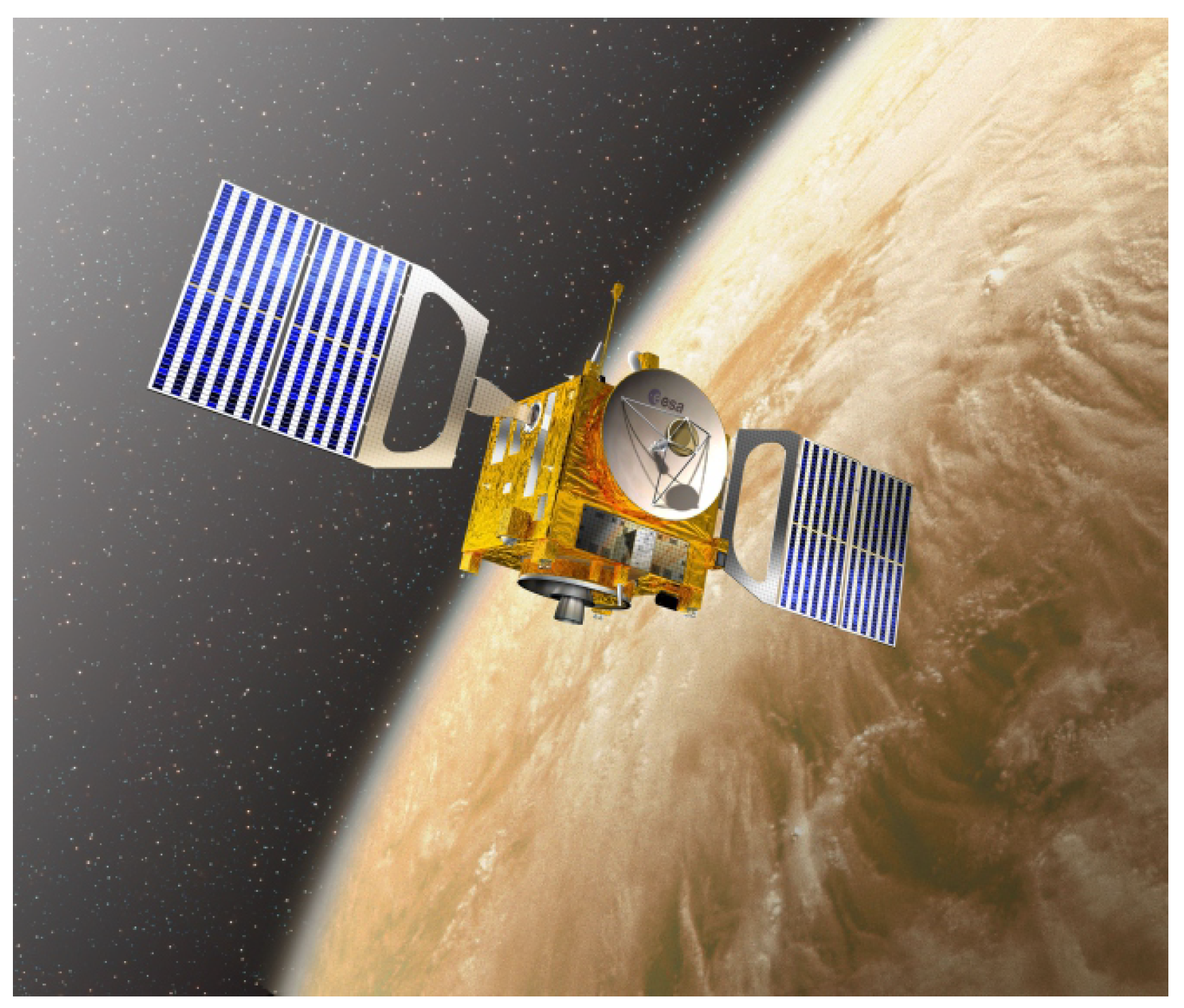
Figure 3.
Conceptual scheme of a GeoSail-type mission scenario applied to a Venus-centered case. The solar sail-induced thrust rotates the apse line of the spacecraft (elliptic) science orbit in order to maintain the apocytherion inside Venus’s induced magnetotail. The spacecraft and Venus move around the Sun along the same plane . The artificial precession of the apse line can be maintained, theoretically, for a very long period of time.

Figure 4.
Scheme of the solar sail-based spacecraft’s science orbit around Venus, in which the initial direction of the planetocentric orbit apse line coincides with the Venus–Sun line. In particular, initially, the Sun belongs to the positive direction of the first axis of a classical perifocal reference frame. The Sun–Venus distance is a constant of motion, and its value is high enough to assume that the Sun rays arrive parallel to the solar sail-based spacecraft.

Figure 5.
Sketch of a Sun-facing solar sail in a Venus-centered mission scenario in which the direction of the incoming Sun rays is coincident with the elliptic orbit apse line. Note that the Sun belongs to the apse line of the science orbit at a distance approximately equal to , which is considered a constant of motion.

Figure 6.
Variation of the dimensionless components of the solar sail-induced propulsive acceleration vector with the spacecraft true anomaly , according to Equations (14) and (15).

Figure 7.
Variation of with obtained by the numerical integration of the Lagrange planetary equations (black line), when , , and . The red dashed line indicates the rotation of the Venus–Sun line during the spacecraft’s revolution around the planet. Note how the black and red dashed lines overlap when .

Figure 8.
Variation of the dimensionless semimajor axis and the eccentricity with , as obtained by the numerical integration of Lagrange planetary equations (in Gaussian form), when , , and .
Figure 8.
Variation of the dimensionless semimajor axis and the eccentricity with , as obtained by the numerical integration of Lagrange planetary equations (in Gaussian form), when , , and .

Figure 9.
Parametric study of the required solar sail characteristic acceleration as a function of the pericytherion and apocytherion dimensionless radii: (a) surface plot of ; (b) contour plot of .
Figure 9.
Parametric study of the required solar sail characteristic acceleration as a function of the pericytherion and apocytherion dimensionless radii: (a) surface plot of ; (b) contour plot of .

Figure 10.
Dimensionless apocytherion radius as a function of the dimensionless pericytherion radius when the solar sail required characteristic acceleration is .
Figure 10.
Dimensionless apocytherion radius as a function of the dimensionless pericytherion radius when the solar sail required characteristic acceleration is .

Figure 11.
Schematic concept of the (simplified) cylindrical shadow model, which was used to determine the solar sail’s required performance in the presence of a period of eclipse.
Figure 11.
Schematic concept of the (simplified) cylindrical shadow model, which was used to determine the solar sail’s required performance in the presence of a period of eclipse.

Figure 12.
The required solar sail’s characteristic acceleration as a function of the pericytherion and apocytherion dimensionless radii in the presence of a period of eclipse: (a) contour plot of ; (b) case of .
Figure 12.
The required solar sail’s characteristic acceleration as a function of the pericytherion and apocytherion dimensionless radii in the presence of a period of eclipse: (a) contour plot of ; (b) case of .

Figure 13.
Function , in the presence of a period of eclipse, when , , and . The black line indicates the output of an orbit simulator, while the red dashed line indicates the rotation of the Venus–Sun line during the spacecraft revolution around the planet.
Figure 13.
Function , in the presence of a period of eclipse, when , , and . The black line indicates the output of an orbit simulator, while the red dashed line indicates the rotation of the Venus–Sun line during the spacecraft revolution around the planet.

Disclaimer/Publisher’s Note: The statements, opinions and data contained in all publications are solely those of the individual author(s) and contributor(s) and not of MDPI and/or the editor(s). MDPI and/or the editor(s) disclaim responsibility for any injury to people or property resulting from any ideas, methods, instructions or products referred to in the content. |
© 2024 by the author. Licensee MDPI, Basel, Switzerland. This article is an open access article distributed under the terms and conditions of the Creative Commons Attribution (CC BY) license (https://creativecommons.org/licenses/by/4.0/).
Share and Cite
MDPI and ACS Style
Quarta, A.A. Venus Magnetotail Long-Term Sensing Using Solar Sails. Appl. Sci. 2024, 14, 8016. https://doi.org/10.3390/app14178016
AMA Style
Quarta AA. Venus Magnetotail Long-Term Sensing Using Solar Sails. Applied Sciences. 2024; 14(17):8016. https://doi.org/10.3390/app14178016
Chicago/Turabian StyleQuarta, Alessandro A. 2024. "Venus Magnetotail Long-Term Sensing Using Solar Sails" Applied Sciences 14, no. 17: 8016. https://doi.org/10.3390/app14178016
Note that from the first issue of 2016, this journal uses article numbers instead of page numbers. See further details here.