Abstract
Since robustness is only maintained on the sliding-mode surface, sliding mode control is inherently non-globally stable. Therefore, reducing the time to reach the sliding mode is crucial for enhancing sliding mode robustness. To improve the performance of conventional super-twisting reaching law (CSTRL) further, we propose a fast-terminal super-twisting reaching law (FTSTRL) designed to improve the quality of sliding mode control. This approach incorporates a terminal term and an exponential term with the CSTRL to ensure rapid convergence. The effectiveness of the designed FTSTRL is validated by comparing it to the CSTRL and a new sliding mode reaching law, demonstrating its superior performance. Finally, integrated square error (ISE), integrated time square error (ITSE), integrated absolute error (IAE), and integrated time absolute error (ITAE) are employed for detailed comparative and quantitative analyses of the simulation results.
1. Introduction
Permanent magnet synchronous motor (PMSM) servo systems can have many excellent features, which are simple construction, high dependability, and low noise [1,2]. Thus, PMSM servo systems are commonly applied in industrial manufacturing, electric vehicles, and other application domains where strict and efficient velocity control is needed [3,4]. But it is difficult to formulate a control scheme for the operation of the PMSM drive system because the PMSM is subjected to several disturbances which include the load torque and parameter uncertainties [5,6], which will significantly affect the speed control of the PMSM. Thus, the results achieved by the traditional linear control methods like the one presented above, the PI control strategy, are low primarily owing to the fact that a nonlinear system has been controlled directly with a linear PI controller [7]. As the related digital signal processing technology and power electronics technology have advanced in the recent years, more and more new nonlinear control methods based on the modern control theory have been applied into the control system of the PMSM to overcome some of the problems coming from the traditional PI controllers, which include active disturbance rejection control [8,9], model predictive control [10,11], intelligence control [12,13], and sliding mode control (SMC) [14,15,16].
In contrast to the other control strategies, SMC is a special nonlinear control, which is widely used in all modern motion control systems. Thus, SMC has been proven to be less complex, dependable, and significantly robust. However, this results in the problem of limiting external interference and the variation of parameters by expanding the sign-function switching gain of the sliding mode. On one hand, the increase in gain can enhance the robustness of SMC; however, on the other hand, the increase in gain will lead to the chattering problem in the system. To enhance the control performance of the conventional SMC control and decrease the chattering effect on the system, many advanced SMC methods have been developed [17,18,19].
Designing SMC using sliding mode reaching laws has become a prevalent method due to its simplicity and computational efficiency, leading to extensive research in recent years [17,20]. The purpose of the reaching law is to ensure that state trajectories reach a specified sliding surface within a finite time. However, conventional sliding mode reaching laws often suffer from slow reaching, regardless of the system’s proximity to the sliding surface [21]. This issue can adversely affect dynamic performance and disturbance rejection capability in practical applications. To accelerate the reaching process of this method, a terminal sliding mode reaching law proposed in [22] aims to accelerate convergence and reduce chattering, but it slows down when the system state is far from the sliding-mode surface. An adaptive sliding mode controller based on a novel sliding mode reaching law, designed for the speed control of PMSM in [23], effectively reduces chattering and shortens convergence time. Moreover, a sliding mode control method based on a new sliding mode reaching law (NSMRL) is proposed, incorporating the system state variable and a power term bounded by the absolute value of the switching function. This allows the reaching law to be expressed in two forms, effectively suppressing inherent chattering and increasing the speed at which the system state reaches the sliding-mode surface [24].
Since disturbance observers can compensate for external disturbances, they can improve the control quality of the system, as indicated in [25]. By designing a time-varying switching gain and a sliding surface, an improved SMC based on a nonlinear disturbance observer (DOB) is developed to counteract disturbances and ensure closed-loop stability. This method offers two main benefits: the exponential decay of the switching gain reduces chattering, and a disturbance-dependent function which is the switching gain coefficient maintains nominal system performance [26]. Moreover, paper [27] proposes a novel sliding mode control strategy combined with a fast-terminal sliding mode disturbance observer (FTSMDO) to address parameter variations in permanent magnet in-wheel motors. The sliding mode power converging law enhances the controller’s response speed, while the FTSMDO compensates for parameter variations to improve robustness.
To enhance PMSM control and improve motor performance, this paper proposes a composite control strategy incorporating extended state disturbance observer (ESDO) and fast-terminal super-twisting sliding mode control (FTSTSMC) algorithms for superior speed control in PMSM systems. Additionally, a new fast-terminal super-twisting reaching law (FTSTRL) is integrated into FTSTSMC to reduce reaching time. The main contributions of this paper are summarized as follows:
- An FTSTRL is built to shorten the reaching time from the initial value to the sliding surface to enhance the robustness of sliding mode control.
- In terms of anti-interference, the FTSTSMC demonstrates strong anti-interference capabilities due to the application of the FTSTRL.
- There was coordination between the ESDO and the FTSTSMC to achieve feedforward compensation.
- This was validated by comparing the FTSTRL with the CSTRL and NSMRL, using metrics like integrated square error (ISE), integrated time square error (ITSE), integrated absolute error (IAE), and integrated time absolute error (ITAE) for detailed comparative and quantitative analyses.
The structure of the remaining sections is as follows: Section 2 introduces the mathematical model of the three-phase PMSM. Section 3 covers the controller design. Section 4 details the ESDO for estimating and feeding back disturbances to the FTSTSMC. Section 5 presents a simulation study validating the proposed approaches. Finally, Section 6 summarizes our conclusions.
2. PMSM Modeling
To simplify the analysis, the following assumptions are made when developing the mathematical model of a PMSM [20]:
- Stator core saturation is ignored, assuming the magnetic circuit is linear and inductance parameters remain constant.
- Core eddy current and hysteresis losses are neglected.
- The electrical conductivity of the rotor’s permanent magnet material is assumed to be zero.
- There are no damper windings on the rotor.
- The currents in the stator are three-phase balanced sine waves.
The mathematical model of the PMSM in the axis coordinate system is as follows:
where the symbols represent the following:
- and represent the voltages along the d-axis and q-axis, respectively.
- R denotes the stator resistance.
- and indicate the currents along the d-axis and q-axis, respectively.
- and signify the inductances along the d-axis and q-axis, respectively.
- p is the number of pole pairs.
- is the motor’s mechanical angular velocity.
- is the flux linkage of the permanent magnet.
For a surface-mounted PMSM with , the torque equation is given by
The motion equations of the PMSM [20] can be expressed as follows:
where B signifies the viscous friction coefficient, J represents the moment of inertia, and indicates the load torque. Taking into account the variations present in Equation (3), Equation (4) can be obtained as follows:
where , , and represent the control laws to be designed. The variations in motor parameters are denoted by , and , while d represents the disturbances due to parameter and load changes as follows:
3. Controller Design
3.1. Traditional Super-Twisting Reaching Law
The design of a sliding mode controller typically involves the following steps:
- Selecting an appropriate sliding surface.
- Designing the control law to ensure that the system trajectory converges to the sliding surface under the influence of the control law.
A conventional sliding surface is usually chosen as follows:
where s represents the traditional sliding surface, e denotes the speed tracking error, and is the reference speed value. The derivative of s is taken and substituted it into Equation (4) in the following equation:
The traditional super-twisting reaching law is as follows [28]:
where and are the switching gains of the sliding mode control. Combining Equations (7) and (8), the equation can be expressed as follows:
From Equation (9), the speed sliding mode control law can be obtained as follows:
3.2. Fast-Terminal Super-Twisting Reaching Law
Although traditional super-twisting reduces chattering compared to the traditional reaching law, the reaching time still needs to be shortened to achieve better performance. In order to improve the performance of the traditional super-twisting reaching law, a new type of FTSTRL is used, which is expressed as
where are positive scalars and . When the system state s is far from zero, the convergence time is mainly determined by the terminal attractor and . However, when the system state s is close to the equilibrium state 0, the convergence time is primarily determined by the equation with s exhibiting an exponential decay. Therefore, Equation (11) incorporates a terminal attractor, ensuring finite-time convergence of the system state, while retaining the rapidity of linear sliding modes near the equilibrium state. This results in the system state converging quickly and accurately to the equilibrium state. The inclusion of the terminal term enhances the dynamic response performance of the system when is relatively large. By selecting a sufficiently small , the system state can reach a sufficiently small area of the sliding surface and then converge to the equilibrium state along the sliding surface.
3.3. Design of the Sliding Mode Controller for the Speed Loop via the FTSTRL
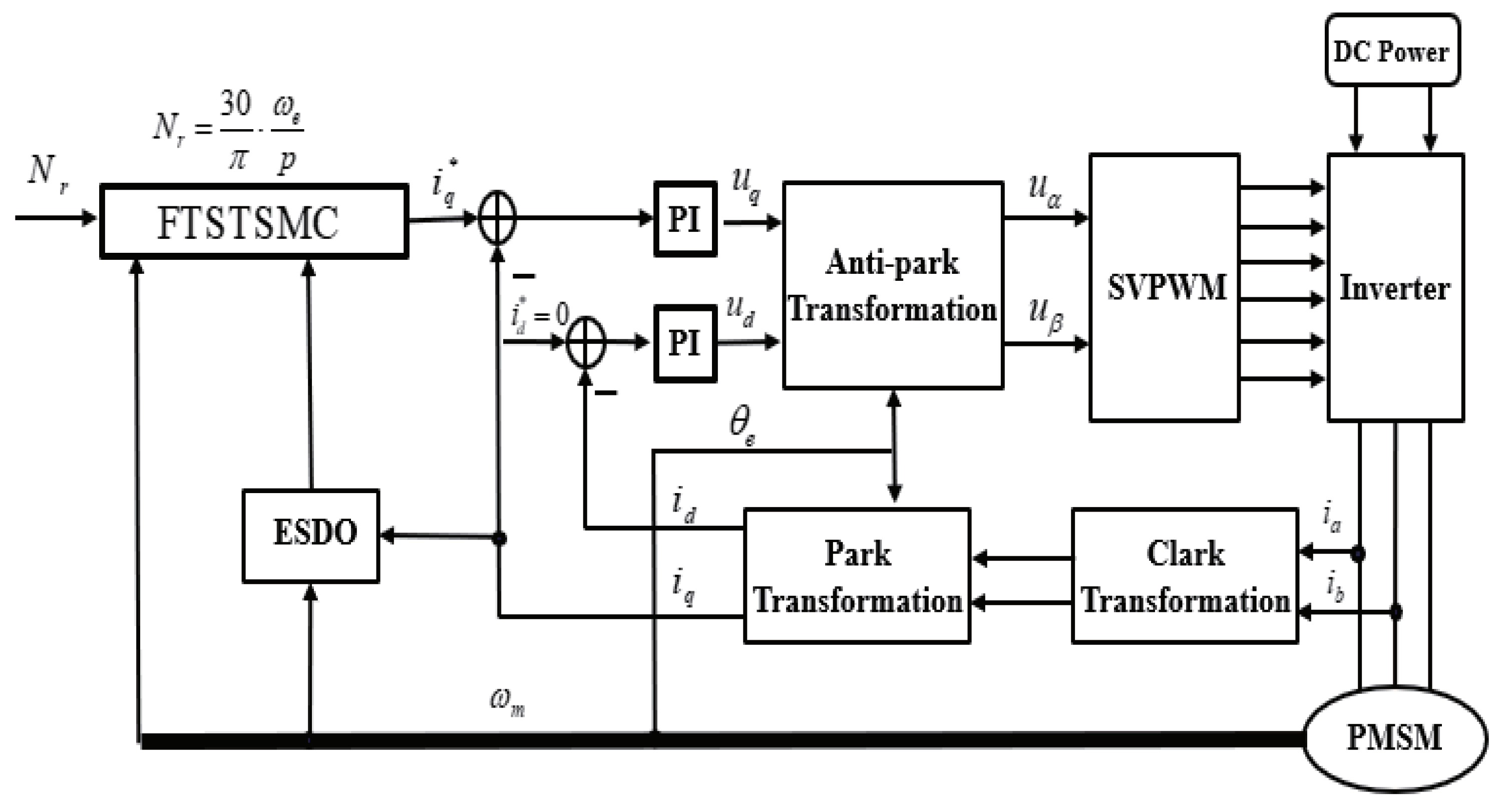
An entire control block including fast-terminal super-twisting sliding mode control and an extended state disturbance observer is shown in Figure 1. This robust performance is achieved by continuously adjusting the control input to compensate for any disturbances and deviations from the desired speed. The speed loop operates by utilizing feedback from the actual motor speed, comparing it to the reference speed, and making real-time adjustments to the control signals. This dynamic adjustment process helps maintain consistent performance, minimizing the impact of external disturbances and parameter variations, and ensuring smooth and reliable operation of the system.
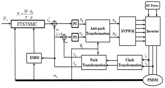
Figure 1.
Entire control block including fast-terminal super-twisting sliding mode control and extended state disturbance observer.
The speed tracking error and sliding surface are same as in Equation (7). Therefore, based on Equation (11), the speed sliding mode control law can be obtained as follows:
Based on the CSTRL, the controllers used for the comparison reference are the same as in Equation (10). For the NSMRL:
Theorem 1.
Configuring the controller as specified in Equation (12) ensures the stability of the motion system.
Proof of Theorem 1.
The candidate Lyapunov function is selected as follows:
To ensure the system is asymptotically stable, it is sufficient to show that according to the Lyapunov stability theorem. This condition indicates that the Lyapunov function V is decreasing over time, leading to the conclusion that the system’s state will converge to equilibrium. Consequently, the system will not exhibit unbounded behavior, ensuring reliable and stable operation under the given controller design.
Substituting Equation (12) into Equation (14), Equation (15) is given by
where [29]. Therefore, Theorem 1 is proved completely. □
4. Disturbance Estimation with Extended State Disturbance Observer
4.1. Design of Extended State Disturbance Observer
As demonstrated by Equation (4), the disturbance term d, an integral component of the PMSM system, significantly affects system performance due to its direct influence on the control input. Enhancing system robustness requires effective compensation for these disturbances. Nonetheless, in practical applications, direct measurement of disturbance values is not feasible. Therefore, developing a disturbance observer to acquire disturbance information becomes crucial. In response to this need, this paper proposes the design of an ESDO for disturbance estimation.
To formulate the system’s state equation, we define the state variable as , which represents the mechanical angular velocity of the system. We also set the output n equal to . Based on Equation (4), which describes the system dynamics, we can derive Equation (17) by substituting and n into the equation. This process involves expressing the system’s behavior in terms of the state variable and output n, leading to the formulation of the state equation that captures the system’s dynamics accurately, as follows:
Here, the disturbance term is introduced as a new state variable . In practical PMSM systems, the disturbance d changes slowly, allowing us to approximate its first-order derivative as zero. This assumption simplifies the analysis and modeling of the system. With this approximation, we can derive the state-space equation of the system, incorporating both the original state variable and the newly defined disturbance state variable. This leads to a more comprehensive representation of the system’s dynamics, which can be expressed as follows:
Next, we implement an extended state feedback mechanism to address the speed estimation error e, using and as the observed variables. This approach allows for more accurate monitoring and compensation of disturbances. The extended disturbance observer is designed to estimate and correct the errors in real time, ensuring the system’s robustness and stability. The detailed design of the extended disturbance observer is as follows:
where , and and are positive real numbers, typically chosen to be very small to ensure a high gain in the observer. By employing this extended state disturbance observer (ESDO), we can achieve convergence where accurately tracks and accurately tracks . This ensures that the observer can effectively estimate and compensate for disturbances in the system.
4.2. Stability Analysis via Extended State Disturbance Observer
To demonstrate that the observer converges within a finite time, we derive the error state equation and analyze its stability using Lyapunov stability theory. This process involves formulating the error dynamics between the estimated states and the actual states, followed by constructing a suitable Lyapunov function. By showing that the derivative of this Lyapunov function is negative definite, we can prove that the error state converges to zero in finite time, ensuring the observer’s effectiveness and robustness.
Theorem 2.
Based on Lyapunov stability theory, the observer achieves stability when the convergence condition is satisfied, as shown below [30]:
Proof of Theorem 2.
The error state variables of the observer are defined as :
where . Therefore, the error state equation of the extended observer is expressed as follows:
where , since
and
The characteristic equation of the matrix A is given by the following:
where I represents the identity matrix, denotes the eigenvalue of A, and A can be made Hurwitz by appropriately choosing and . Consequently, for any symmetric positive definite matrix Q, there exists a symmetric positive definite matrix P such that
The candidate Lyapunov function for the observer is defined as follows:
Assuming the disturbance derivative is bounded, i.e., , and using Equation (17), we derive the following:
Therefore, the observer can be stabilized when . As a result, the convergence condition of the observer is obtained as shown in Equation (20). This completes the proof of Theorem 2. □
Substituting the observed disturbance and the perturbation value of the load torque d into Equation (12), we obtain the modified equation that accounts for the influence of these disturbances on the system. By integrating these observed values, we can enhance the accuracy and robustness of the control strategy, ensuring that the system can effectively compensate for external disturbances and parameter variations. This results in a more stable and reliable performance. The modified equation is as follows:
Remark 1.
Equation (20) shows that the convergence rate of γ is inversely proportional to the parameter ε. This implies that as the value of ε decreases, the convergence rate of γ correspondingly increases. In practical terms, this relationship indicates that by selecting a smaller value for ε, we can achieve a faster convergence rate for γ. This behavior is critical in control system design, as it allows for more rapid stabilization and response to disturbances. Therefore, careful tuning of ε is essential to balance the trade-off between convergence speed and system performance, ensuring that the system can quickly reach its desired state while maintaining robustness and stability.
5. Simulation
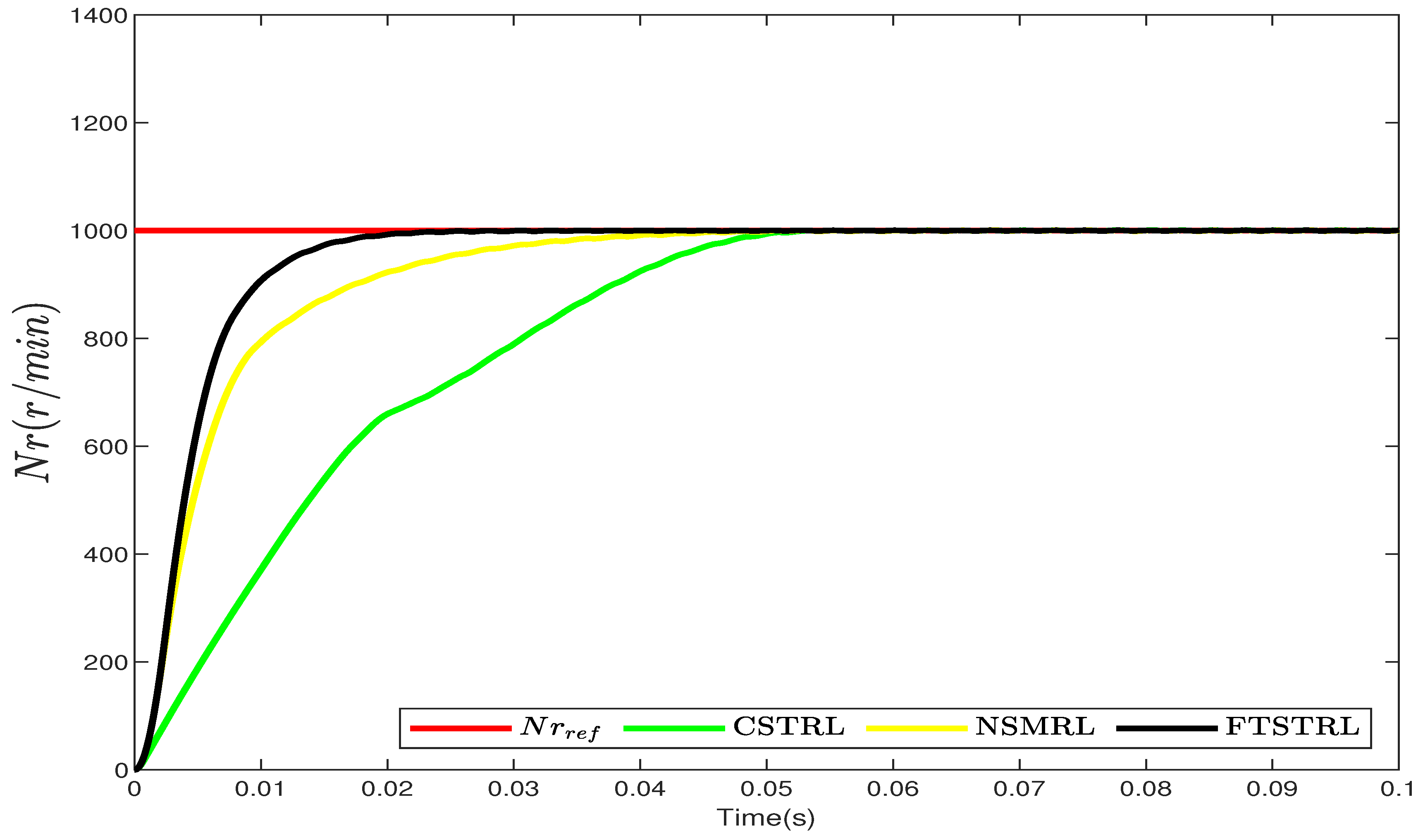
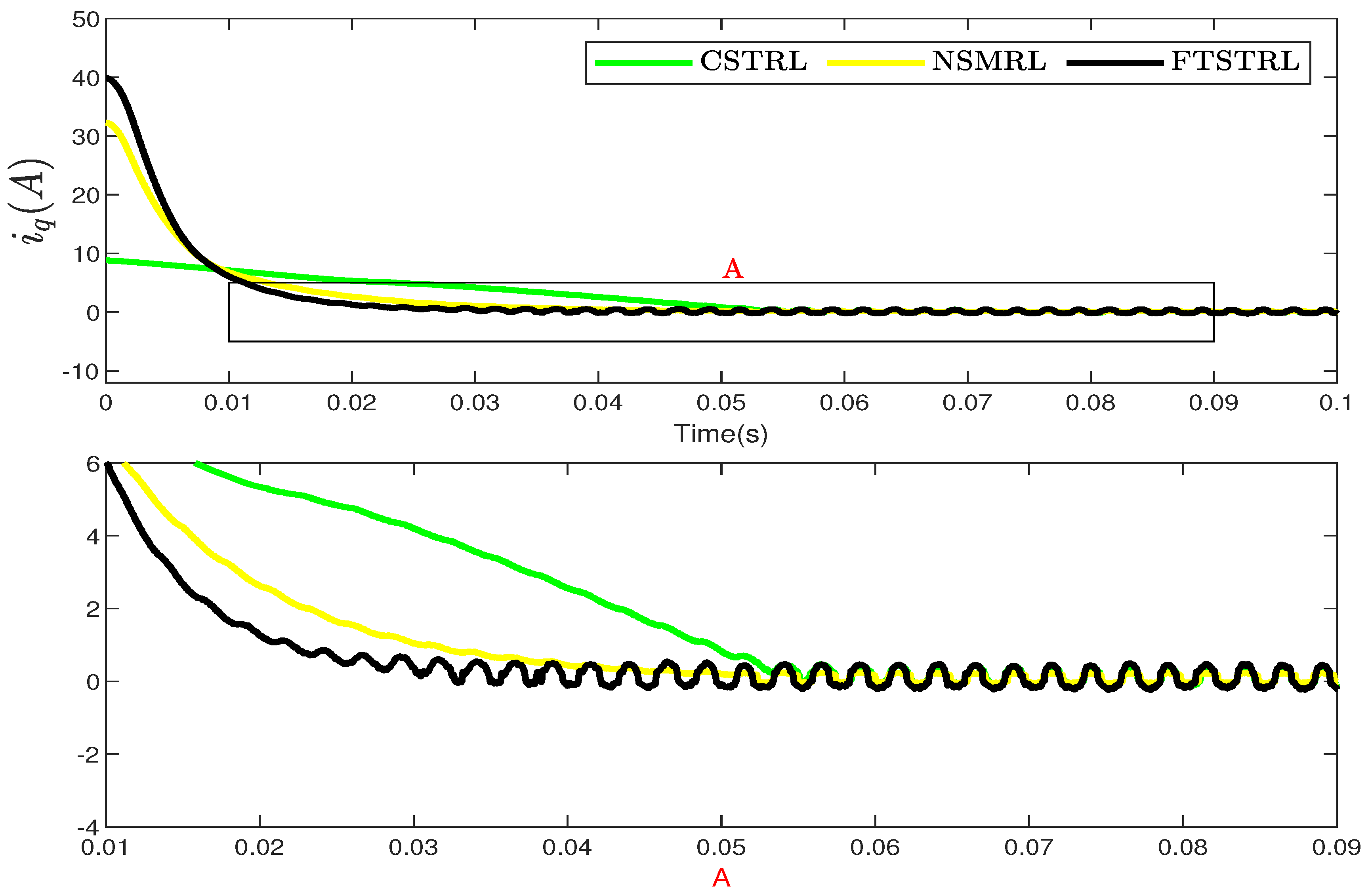
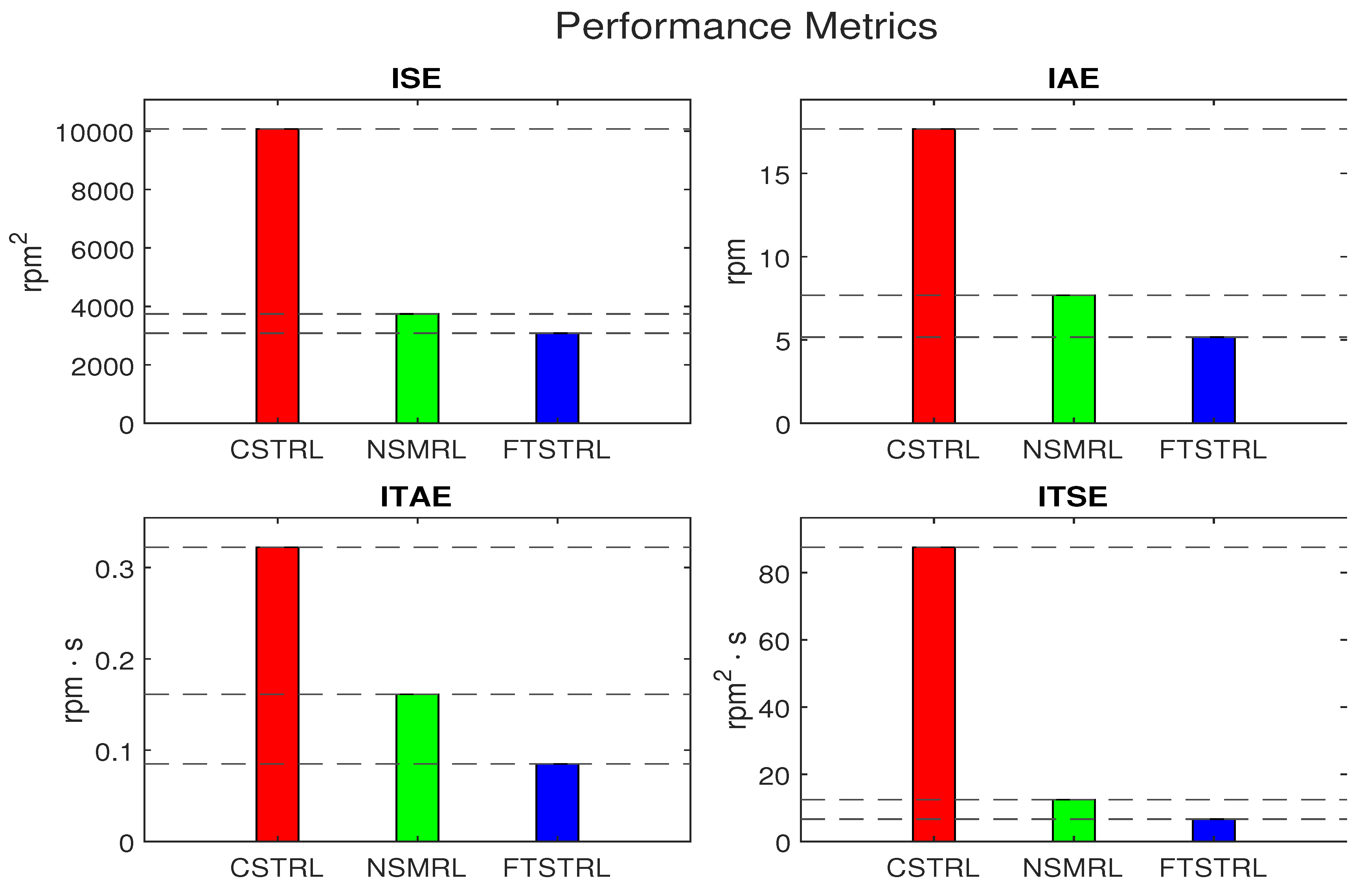
This section showcases the simulation results that validate the effectiveness of the proposed control strategy. Detailed simulation parameters for the model, observer, and controllers are provided in Table 1, Table 2 and Table 3, respectively. The parameters in Table 2 and Table 3 were obtained through multiple rounds of tuning and experience. These tables list the specific values and configurations employed in the simulations, ensuring that the results are clear and reproducible. The letter A, B, C represent the enlarged part and correspond to the corresponding figures. Figure 2 illustrates a comparison of the time taken by the CSTRL, NSMRL, and FTSTRL systems to achieve speed regulation at a target of 1000 rpm. This comparison highlights the relative performance and efficiency of each control strategy. As shown, the FTSTRL reached the desired speed of 1000 rpm in just 0.02 s, whereas the CSTRL and NSMRL took 0.05 and 0.048 s, respectively. This indicates that the FTSTRL outperformed both the CSTRL and NSMRL. Figure 3 illustrates the corresponding variations in current, reflecting the changes in control inputs. Moreover, Figure 4 presents an in-depth comparative and quantitative analysis of the speed regulation simulation results. This analysis employs key performance metrics such as ISE, ITSE, IAE, and ITAE. By leveraging these metrics, we can rigorously evaluate each control strategy’s performance, focusing on its precision, response time, and overall effectiveness.

Table 1.
Parameter values of the PMSM [31].
Table 2.
Parameter values of the ESDO.
Table 3.
Parameter values of the 3 reaching laws.
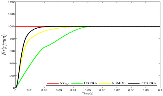
Figure 2.
Comparison between CSTRL, NSMRL, and FTSTRL for speed regulation.

Figure 3.
Comparison between CSTRL, NSMRL, and FTSTRL for control input of speed regulation.

Figure 4.
Performance indexes such as ISE, IAE, ITAE, and ITSE for speed regulation.
Remark 2.
To guarantee a fair comparison, all three controllers are implemented with the same ESDO and identical parameter settings. The exact parameters used for the simulations are comprehensively listed in Table 2. This uniformity in the setup ensures that any observed differences in performance can be attributed solely to the control strategies themselves, rather than variations in the observer or parameter configurations.
Remark 3.
The parameter values for the same parameters are identical and are listed in Table 3 along with their corresponding values.
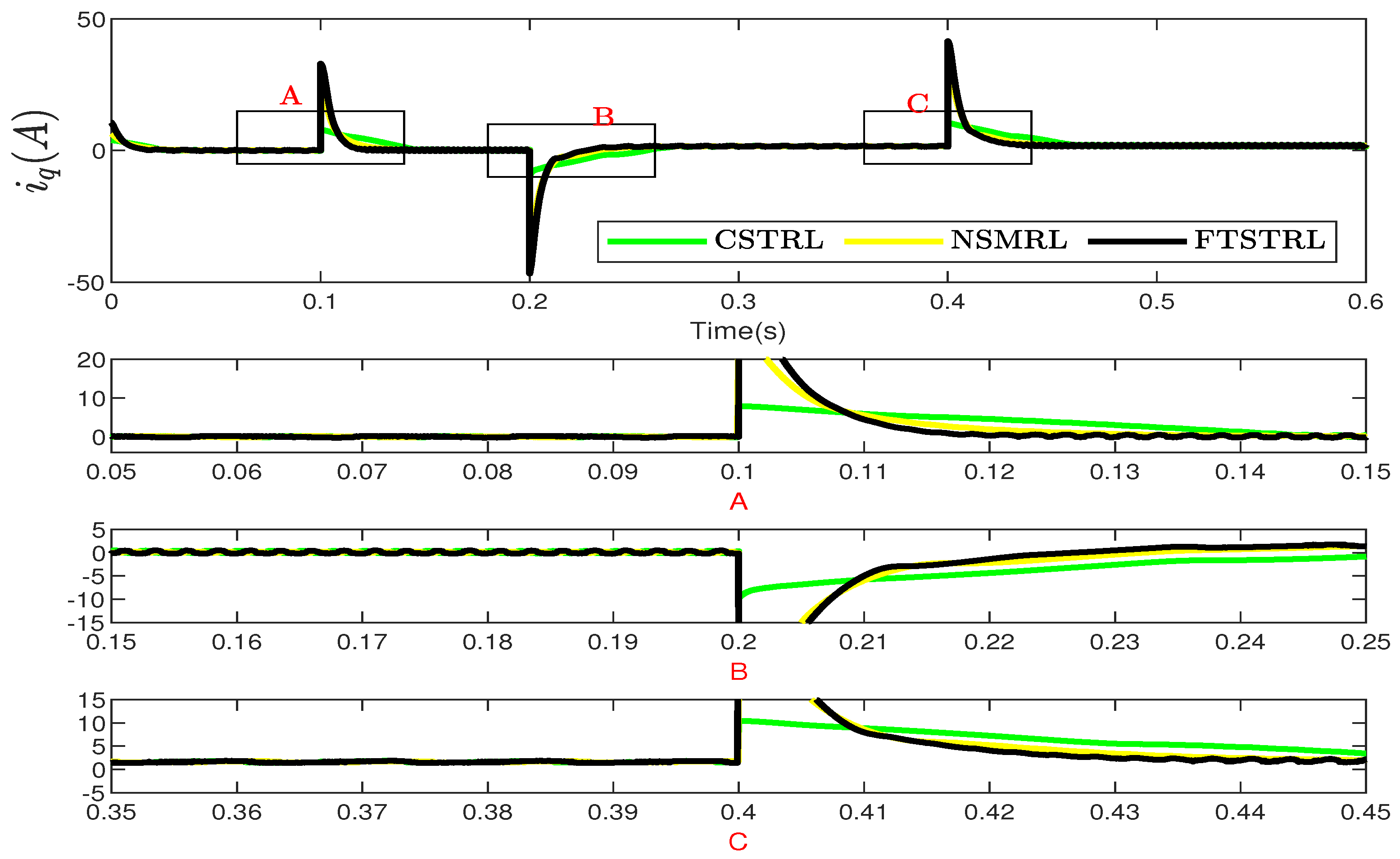
Figure 5 illustrates the speed tracking performance of the CSTRL, NSMRL, and FTSTRL. The desired speed undergoes several changes: from 0 to 200 rpm at 0.01 s, from 200 to 900 rpm at 0.11 s, from 1000 to −200 rpm at 0.22 s, and from −200 to 800 rpm at 0.42 s. The results clearly show that the FTSTRL achieves superior tracking performance compared to the CSTRL and NSMRL. Figure 6 depicts the corresponding current variations, which reflect the control input. Additionally, Figure 7 presents a detailed comparative and quantitative analysis of the simulation results for speed tracking, utilizing the metrics of ISE, ITSE, IAE, and ITAE.
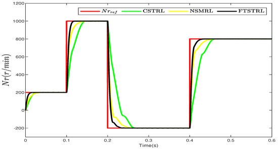
Figure 5.
Comparison between CSTRL, NSMRL, and FTSTRL for speed tracking.
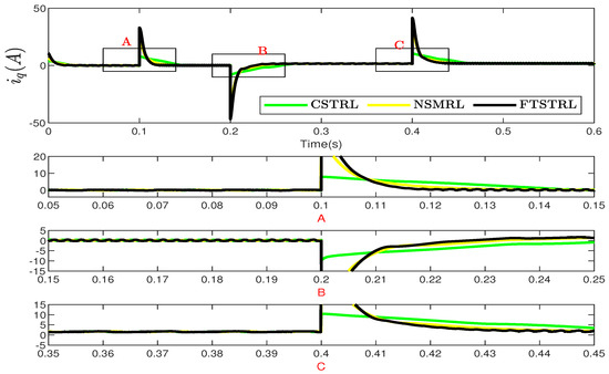
Figure 6.
Comparison between CSTRL, NSMRL, and FTSTRL for control input of speed tracking.
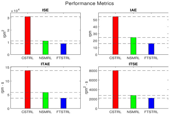
Figure 7.
Performance metrics such as ISE, IAE, ITAE, and ITSE for speed tracking.
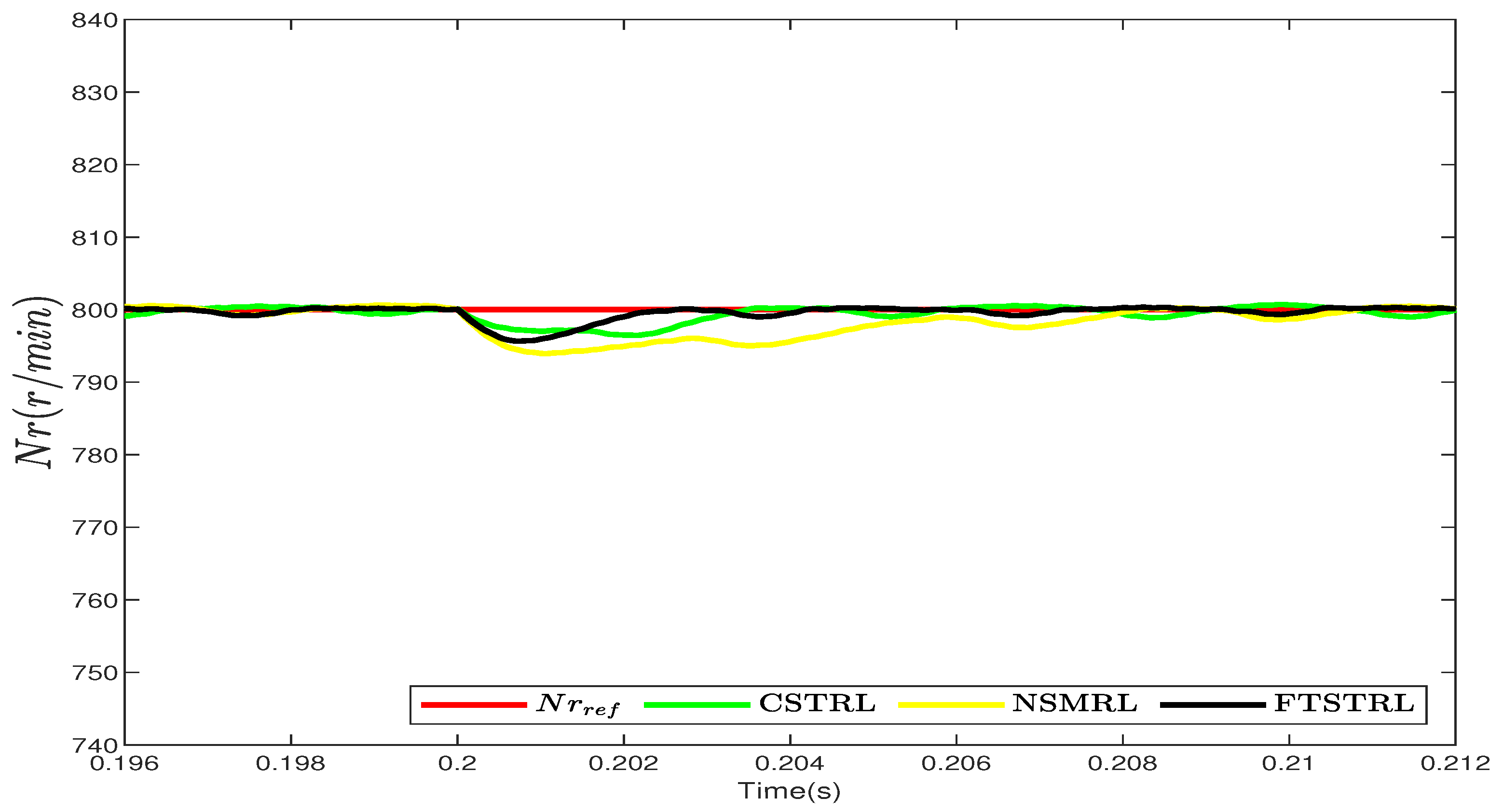
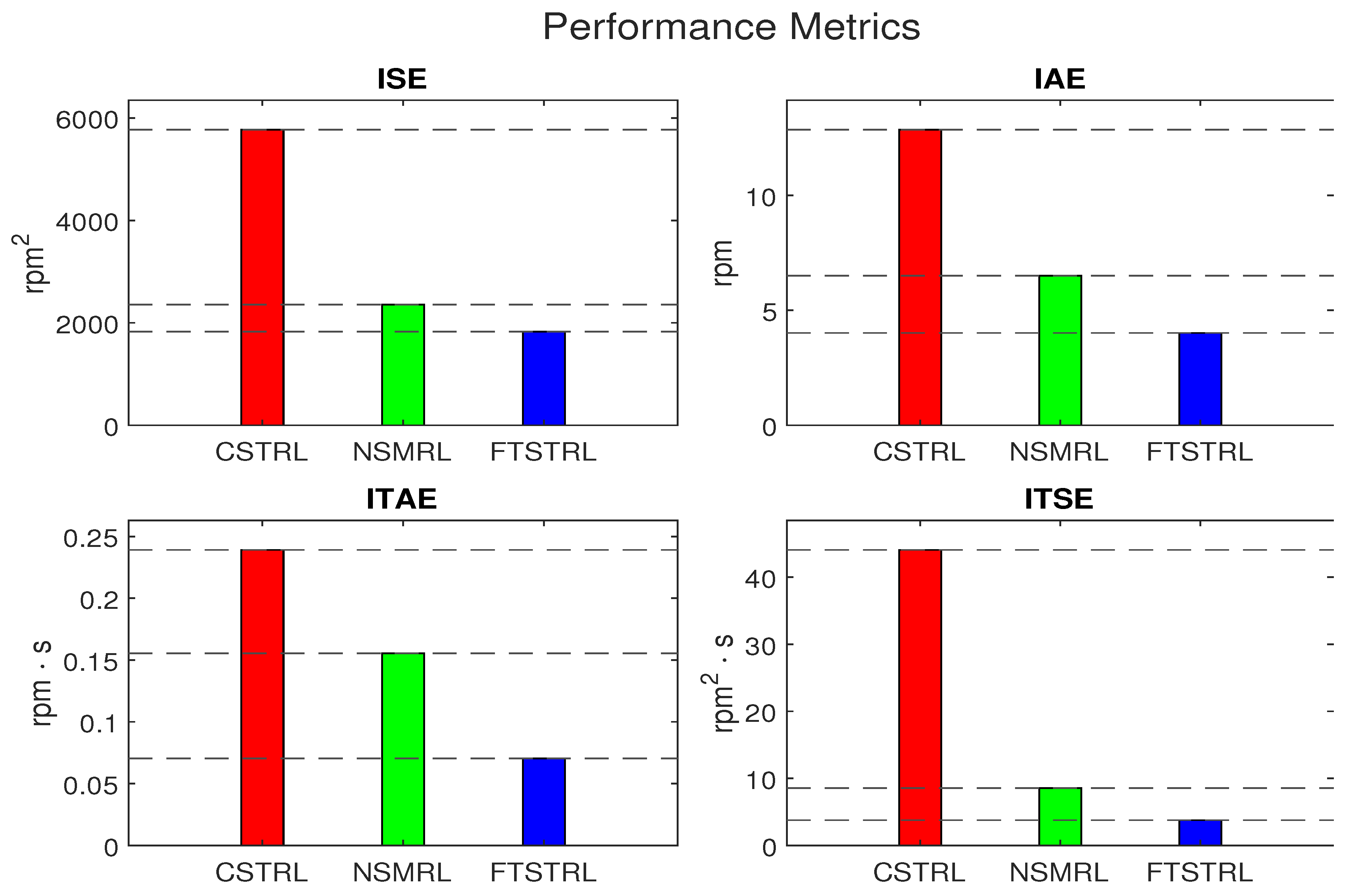
Figure 8 illustrates the motor’s speed response when subjected to a sudden load of 3 N· m applied at 0.2 s. The results demonstrate that the FTSTRL method exhibits a significantly smaller deviation from the target speed compared to the CSTRL and NSMRL methods, indicating superior performance in maintaining speed stability. Figure 9 shows the corresponding variations in current in response to the load change. Additionally, Figure 10 provides an in-depth comparative and quantitative analysis of the simulation results for this sudden load test, utilizing metrics such as ISE, ITSE, IAE, and ITAE. These analyses highlight the effectiveness of the FTSTRL method in handling abrupt disturbances and maintaining system performance.
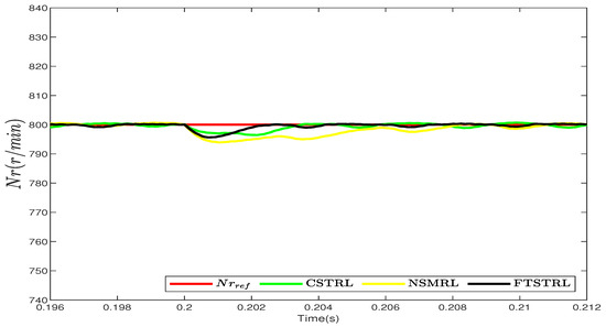
Figure 8.
Comparison between CSTRL, NSMRL, and FTSTRL for sudden load test.
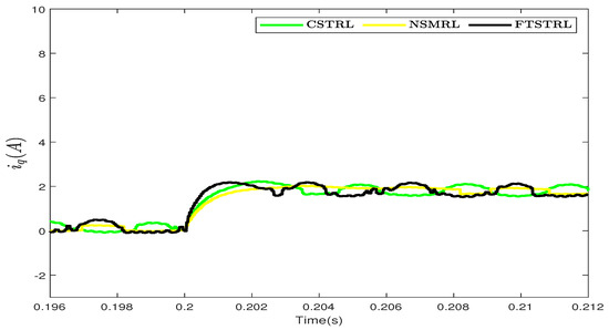
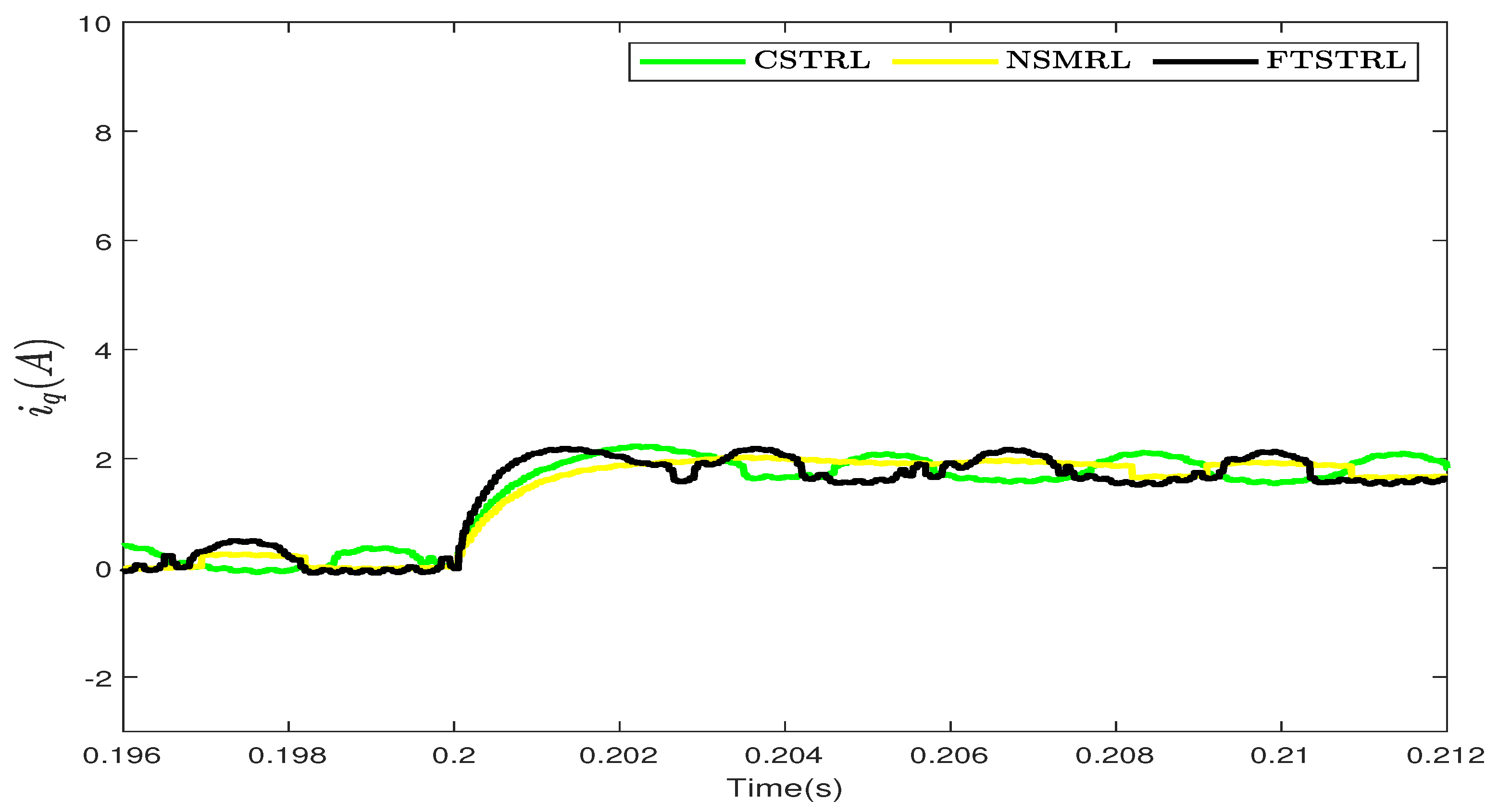
Figure 9.
Comparison between CSTRL, NSMRL, and FTSTRL for control input of sudden load test.
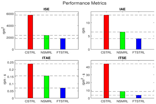
Figure 10.
Performance indexes such as ISE, IAE, ITAE, and ITSE for sudden load test.
As shown in Figure 2, Figure 3, Figure 4, Figure 5, Figure 6, Figure 7 and Figure 8, the FTSTRL shows good performance compared with the CSTRL and NSMRL. Moreover, Figure 4, Figure 7 and Figure 10 show the superiority of the FTSTRL in terms of errors. The results show that the controller using the FTSTRL has the smallest errors in ISE, ITSE, IAE, and ITAE.
6. Conclusions
To balance the critical need for rapid market responsiveness with the stringent requirements for thorough certification of embedded systems, the FTSTRL was developed. This approach represents a significant advancement in control strategies, particularly in the context of embedded systems. The FTSTRL was achieved through collaboration with an ESDO and integration with an FTSTSMC. By combining these elements, the FTSTRL facilitates feedforward compensation, which is essential for improving the system’s responsiveness and accuracy. The inclusion of the FTSTRL within the FTSTSMC significantly enhances the system’s robustness by effectively reducing the impact of interferences. Comparative performance evaluations were conducted to assess the effectiveness and reliability of the FTSTRL against other existing models, such as the CSTRL and NSMRL. These evaluations employed key performance metrics, including ISE, ITSE, IAE, and ITAE, providing a comprehensive quantitative basis for comparison, ensuring that the advantages of the FTSTRL are clearly demonstrated in simulations. Future research will involve applying the FTSTRL to real motors in practical applications. This step is crucial for validating the control strategy’s performance under real-world conditions, ensuring that the FTSTRL not only performs well in simulations but also delivers robust, reliable control in the field.
Author Contributions
This paper was produced by all the authors. H.W. and G.Z. conceived the idea, performed the analysis, and designed the simulation; H.W. and X.L. carried out the numerical simulations; and H.W. wrote the manuscript. All authors have read and agreed to the published version of the manuscript.
Funding
This work was supported in part by the Science and Technology Innovation Project of the National Shuohuang Railway Company (SHTL-22-17) and in part by the Key Research Development Project of Nanjing Polytechnic Institute under Grant NJPI-2021-14.
Institutional Review Board Statement
Not applicable.
Informed Consent Statement
Not applicable.
Data Availability Statement
The original contributions presented in the study are included in the article; further inquiries can be directed to the corresponding author.
Conflicts of Interest
The authors declare that this study received funding from National Shuohuang Railway Company. The funder was not involved in the study design, collection, analysis, interpretation of data, the writing of this article or the decision to submit it for publication.
References
- Skowron, M.; Orlowska-Kowalska, T.; Kowalski, C.T. Detection of permanent magnet damage of PMSM drive based on direct analysis of the stator phase currents using convolutional neural network. IEEE Trans. Ind. Electron. 2022, 69, 13665–13675. [Google Scholar] [CrossRef]
- Wang, X.; Ren, S.; Xiao, D.; Meng, X.; Fang, G.; Wang, Z. Fault-Tolerant Control of Open-Circuit Faults in Standard PMSM Drives Considering Torque Ripple and Copper Loss. IEEE Trans. Transp. Electrif. 2024, 10, 4239–4251. [Google Scholar] [CrossRef]
- Chen, Q.; Li, Y.; Hong, Y.; Shi, H. Prescribed-Time Robust Repetitive Learning Control for PMSM Servo Systems. IEEE Trans. Ind. Electron. 2024, 71, 14753–14763. [Google Scholar] [CrossRef]
- Kiselev, A.; Catuogno, G.R.; Kuznietsov, A.; Leidhold, R. Finite-Control-Set MPC for Open-Phase Fault-Tolerant Control of PM Synchronous Motor Drives. IEEE Trans. Ind. Electron. 2020, 67, 4444–4452. [Google Scholar] [CrossRef]
- Nguyen, H.V.; Suleimenov, K.; Nguyen, B.H.; Vo-Duy, T.; Ta, M.C.; Duc Do, T. Dynamical Delay Unification of Disturbance Observation Techniques for PMSM Drives Control. IEEE/ASME Trans. Mechatron. 2022, 27, 5560–5571. [Google Scholar] [CrossRef]
- Wu, X.; Huang, S.; Liu, K.; Lu, K.; Hu, Y.; Pan, W.; Peng, X. Enhanced Position Sensorless Control Using Bilinear Recursive Least Squares Adaptive Filter for Interior Permanent Magnet Synchronous Motor. IEEE Trans. Power Electron. 2020, 35, 681–698. [Google Scholar] [CrossRef]
- Zhang, X.; Sun, L.; Zhao, K.; Sun, L. Nonlinear speed control for PMSM system using sliding-mode control and disturbance compensation techniques. IEEE Trans. Power Electron. 2012, 28, 1358–1365. [Google Scholar] [CrossRef]
- Liu, C.; Luo, G.; Chen, Z.; Tu, W. Measurement delay compensated LADRC based current controller design for PMSM drives with a simple parameter tuning method. ISA Trans. 2020, 101, 482–492. [Google Scholar] [CrossRef]
- Tian, M.; Wang, B.; Yu, Y.; Dong, Q.; Xu, D. Discrete-Time Repetitive Control-Based ADRC for Current Loop Disturbances Suppression of PMSM Drives. IEEE Trans. Ind. Inform. 2022, 18, 3138–3149. [Google Scholar] [CrossRef]
- Niu, F.; Chen, X.; Huang, S.; Huang, X.; Wu, L.; Li, K.; Fang, Y. Model predictive current control with adaptive-adjusting timescales for PMSMs. CES Trans. Electr. Mach. Syst. 2021, 5, 108–117. [Google Scholar] [CrossRef]
- Chen, Y.; Wang, X.; Xiao, D.; Ma, D.; Yang, X.; Wang, Z. Model predictive control of five-level open-end winding PMSM drives. IEEE Trans. Transp. Electr. 2024; in press. [Google Scholar] [CrossRef]
- You, S.; Gil, J.; Kim, W. Adaptive Neural Network Control Using Nonlinear Information Gain for Permanent Magnet Synchronous Motors. IEEE Trans. Cybern. 2023, 53, 1392–1404. [Google Scholar] [CrossRef] [PubMed]
- Pang, S.; Zhang, Y.; Huangfu, Y.; Li, X.; Tan, B.; Li, P.; Tian, C.; Quan, S. A Virtual MPC-Based Artificial Neural Network Controller for PMSM Drives in Aircraft Electric Propulsion System. IEEE Trans. Ind. Appl. 2024, 60, 3603–3612. [Google Scholar] [CrossRef]
- Zhang, D.; Hu, J.; Cheng, J.; Wu, Z.G.; Yan, H. A Novel Disturbance Observer Based Fixed-Time Sliding Mode Control for Robotic Manipulators with Global Fast Convergence. IEEE/CAA J. Autom. Sin. 2024, 11, 661–672. [Google Scholar] [CrossRef]
- Feng, J.; Wang, W.; Zeng, H.B. Integral Sliding Mode Control for a Class of Nonlinear Multi-Agent Systems with Multiple Time-Varying Delays. IEEE Access 2024, 12, 10512–10520. [Google Scholar] [CrossRef]
- Zwerger, T.; Mercorelli, P. Optimal control strategies for PMSM with a decoupling super twisting SMC and inductance estimation in the presence of saturation. J. Frankl. Inst. 2024, 361, 106934. [Google Scholar] [CrossRef]
- Junejo, A.K.; Xu, W.; Mu, C.; Ismail, M.M.; Liu, Y. Adaptive speed control of PMSM drive system based a new sliding-mode reaching law. IEEE Trans. Power Electron. 2020, 35, 12110–12121. [Google Scholar] [CrossRef]
- Xu, W.; Junejo, A.K.; Liu, Y.; Islam, M.R. Improved continuous fast terminal sliding mode control with extended state observer for speed regulation of PMSM drive system. IEEE Trans. Veh. Technol. 2019, 68, 10465–10476. [Google Scholar] [CrossRef]
- Wang, Y.; Feng, Y.; Zhang, X.; Liang, J.; Cheng, X. New reaching law control for permanent magnet synchronous motor with extended disturbance observer. IEEE Access 2019, 7, 186296–186307. [Google Scholar] [CrossRef]
- Zhang, D.; Zhang, H.; Li, X.; Zhao, H.; Zhang, Y.; Wang, S.; Ahmad, T.; Liu, T.; Shuang, F.; Wu, T. A PMSM control system for electric vehicle using improved exponential reaching law and proportional resonance theory. IEEE Trans. Veh. Technol. 2023, 72, 8566–8578. [Google Scholar] [CrossRef]
- Zhang, Z.; Yang, X.; Wang, W.; Chen, K.; Cheung, N.C.; Pan, J. Enhanced Sliding Mode Control for PMSM Speed Drive Systems Using a Novel Adaptive Sliding Mode Reaching Law Based on Exponential Function. IEEE Trans. Ind. Electron. 2024, 71, 11978–11988. [Google Scholar] [CrossRef]
- Wang, H.; Shi, L.; Man, Z.; Zheng, J.; Li, S.; Yu, M.; Jiang, C.; Kong, H.; Cao, Z. Continuous fast nonsingular terminal sliding mode control of automotive electronic throttle systems using finite-time exact observer. IEEE Trans. Ind. Electron. 2018, 65, 7160–7172. [Google Scholar] [CrossRef]
- Nguyen, T.H.; Nguyen, T.T.; Nguyen, V.Q.; Le, K.M.; Tran, H.N.; Jeon, J.W. An adaptive sliding-mode controller with a modified reduced-order proportional integral observer for speed regulation of a permanent magnet synchronous motor. IEEE Trans. Ind. Electron. 2021, 69, 7181–7191. [Google Scholar] [CrossRef]
- Wang, Y.; Feng, Y.; Zhang, X.; Liang, J. A New Reaching Law for Antidisturbance Sliding-Mode Control of PMSM Speed Regulation System. IEEE Trans. Power Electron. 2020, 35, 4117–4126. [Google Scholar] [CrossRef]
- Zhao, K.; Jia, N.; She, J.; Dai, W.; Zhou, R.; Liu, W.; Li, X. Robust model-free super-twisting sliding-mode control method based on extended sliding-mode disturbance observer for PMSM drive system. Control Eng. Pract. 2023, 139, 105657. [Google Scholar] [CrossRef]
- Fu, B.; Che, W.; Wang, Q.; Liu, Y.; Yu, H. Improved sliding-mode control for a class of disturbed systems based on a disturbance observer. J. Frankl. Inst. 2024, 361, 106699. [Google Scholar] [CrossRef]
- Huang, H.; Yu, C.; Sun, Z.; Zhang, Y.; Zhao, Z. Sliding mode control strategy based on disturbance observer for permanent magnet in-wheel motor. Sci. Rep. 2024, 14, 16151. [Google Scholar] [CrossRef]
- Levant, A. Sliding order and sliding accuracy in sliding mode control. Int. J. Control 1993, 58, 1247–1263. [Google Scholar] [CrossRef]
- Feng, Y.; Yu, X.; Han, F. On nonsingular terminal sliding-mode control of nonlinear systems. Automatica 2013, 49, 1715–1722. [Google Scholar] [CrossRef]
- Gao, Z. Active disturbance rejection control: A paradigm shift in feedback control system design. In Proceedings of the American Control Conference, Minneapolis, MN, USA, 14–16 June 2006; IEEE: Piscataway, NJ, USA, 2006; p. 7. [Google Scholar]
- Hu, M.; Ahn, H.; Chung, Y.; You, K. Speed regulation for PMSM with super-twisting sliding-mode controller via disturbance observer. Mathematics 2023, 11, 1618. [Google Scholar] [CrossRef]


Disclaimer/Publisher’s Note: The statements, opinions and data contained in all publications are solely those of the individual author(s) and contributor(s) and not of MDPI and/or the editor(s). MDPI and/or the editor(s) disclaim responsibility for any injury to people or property resulting from any ideas, methods, instructions or products referred to in the content. |
© 2024 by the authors. Licensee MDPI, Basel, Switzerland. This article is an open access article distributed under the terms and conditions of the Creative Commons Attribution (CC BY) license (https://creativecommons.org/licenses/by/4.0/).