Abstract
The bladeless wind turbine (BWT) using vortex-induced vibration is a new class of wind turbine that does not have traditional rotating blades and converts wind energy into vibration energy and into electrical energy based on vortex-shedding principles. Since conventional BWTs are only efficient for a small range of wind speeds near the structural resonant frequency, this study proposes a novel bladeless wind turbine that can tune the resonant frequency for a wider range of wind speeds to improve the effective power generation region. This study designed a discrete on–off resonance-shifting module based on a smart material with variable stiffness that can easily tune the structural frequency of the BWT to two different wind speed classes to enhance power generation efficiency. Experiments were conducted to confirm that the designed BWT can shift the resonant frequency of the structure by 60% and can operate in the ranges of light breezes and gentle breezes. Furthermore, a series of experiments present the power generation effectiveness of the proposed BWT under these different wind speed conditions.
1. Introduction
Conventional wind power systems, a representative renewable energy source, generate electricity using blade rotations driven by wind energy, producing at a relatively high efficiency. However, large-scale wind power systems have significant disadvantages, such as high construction costs, a large area required for the installation site, and high noise. Furthermore, wind power systems have an adverse visual impact on the aesthetic environment and pose a threat to birds [1,2]. Furthermore, these systems comprise rotating mechanical parts, such as bearings and blades [3], with a short life cycle that requires frequent maintenance and high operating costs.
To solve these major disadvantages of conventional wind power systems, new approaches have been proposed for wind turbines. In this sense, bladeless wind turbines (BWTs) are a new and promising concept. A small-scale cylinder-type BWT was first proposed in [4]. This pioneering concept is designed using a simple cylinder on a flexible rod that resonates with the vortex-induced vibration (VIV). Its inner structure features a simple design without rotational mechanical parts, thereby reducing manufacturing and maintenance costs. Furthermore, this design is compact, offering a relatively high energy density per area, and it can be installed on rooftops, allowing more freedom at the installation sites.
Vortex-induced vibration (VIV) occurs due to a Karman vortex, which is formed when wind passes through a cylindrical body [5]. The Karman vortex forms a low periodic pressure on the body of the cylinder, which exerts a periodic lifting force on the body perpendicular to the wind velocity. If the vortex-shedding frequency is close to the structural frequency of the BWT, the vortex enters the lock-in range of the resonance, causing the BWT to oscillate [6]. The vibration energy of the BWT’s resonance can be converted into electrical energy with electric generators or smart materials. It is preferable to maintain the BWT’s resonance for maximum vibration when generating energy by keeping the vortex-shedding frequency in the lock-in range.
However, the vortex-shedding frequency is proportional to the wind speed, which depends on the weather conditions. When the wind speed changes, causing the induced vortex frequency to be outside the structural resonance, it decreases the vibration level and consequently dramatically lowers power generation [7]. A solution to increase the efficiency of power generation is to widen the operating lock-in range to expand the wind velocities of the BWT operation.
Several studies have attempted to widen the lock-in range by modifying the aerodynamic design and material. Hu et al. [8] designed a mast shape to expand the aeroelastic resonance range to improve power generation. Ding et al. [9] attached fin-shaped rods to the mast surface and demonstrated that their innovation could expand the frequency band to harvest vibration energy. Furthermore, Chang et al. [10] altered the roughness of the mast surface to widen the vortex frequency band and amplitude. However, these surface design approaches have limitations in actively responding to varying wind speeds [11].
Another approach to expanding the operating lock-in range is to actively tune the BWT’s resonant frequency. A resonance-tuning system is proposed to tune the frequency of the BWT structure to closely match the frequency of the varying input vortex [4,12]. These tuning systems are designed to control the equivalent stiffness of the system, which affects the resonant frequency of the system. A magnetic-force-based tuning module for VIV BWTs was proposed in [4]. This system is composed of two pairs of circular magnets with identical poles facing each other. The first magnet is attached to a flexible rod, whereas the other magnet is fixed to the ground. Additionally, the magnetic repulsion force is proportional to their relative distance, which varies proportionally to the magnitude of the oscillation. This force behaves as a damped harmonic oscillator that broadens the lock-in range [13]. Another study proposed a tuning system for VIV BWTs, featuring a secondary mass added to the main system to broaden the lock-in range. This dual-mass system functions as a tuned mass damper, thus widening the lock-in range [12]. Additionally, in [14], a tuning system that gradually adjusts the spring stiffness in response to changing wind speeds was developed, enabling the BWT system to maintain resonance over a wider range of conditions. This approach significantly enhanced the power generation efficiency of the system by adapting to varying wind speeds and ensuring extended resonance periods.
This study takes a simpler but effective approach to designing a resonance-tuning system for VIV BWTs. The proposed resonance-tuning module uses a variable-stiffness smart material to adaptively control the system’s natural frequency in response to varying wind speeds. There are several candidates for smart materials to adjust the stiffness. Shape-memory alloys (SMAs) are a widely applied smart material for stiffness control. However, these alloys are extremely rigid, and their response time is relatively long [15]. Magnetorheological elastomers (MREs) are flexible and elastic smart materials with the property of stiffness variation. MREs are elastomers that consist of a polymeric matrix with embedded micro-sized ferromagnetic particles. Under the influence of an external magnetic field, the iron particles align in a chain formation, causing the overall elastic modulus to increase [16,17]. Furthermore, MREs have a relatively short response time for a stiffness change of a few milliseconds [18]. MREs are often applied to tune the resonant frequency of vibration systems, as reported in the literature [19,20,21,22]. An MRE-based TVA was designed for adaptive vibration suppression by controlling MRE stiffness with permanent magnets [22]. As this material is flexible and can be designed in any shape, it can be easily integrated into existing BWT structures.
Therefore, this study aims to design an MRE-based on–off resonance-tuning module for small-scale BWTs that can improve the overall energy generation efficiency by widening the operating wind speeds. The proposed resonance-tuning module has two shift modes: the low-stiffness (Low-K) mode and high-stiffness (High-K) mode.
For a light breeze of wind, the BWT is tuned with the Low-K mode. When the wind begins to increase the drift from the structural resonance, the BWT is shifted to the High-K mode to increase the structural resonance of the BWT to match the new vortex frequency and maintain the lock-in vibration.
The main contributions of this study are as follows:
- This study proposes a novel bladeless wind turbine that can shift the structural resonance to operate at a wider range of wind speeds to improve the effective power generation region.
- This study designed an on–off resonance-tuning module based on a variable-stiffness smart material that can effectively shift the BWT resonance by 60%.
- A series of experiments validated the widening of the operation range with the Low-K and High-K modes, which improved power generation efficiency by as much as 1.9 times for various wind speeds.
This paper is structured as follows. In Section 2, a brief introduction to a cylinder-type BWT explains the basic principle of vortex-induced vibrations. The hardware design of the proposed system and the system modeling are presented in Section 3 and Section 4. A series of experiments are conducted to validate the change in the natural frequency of the system to increase the lock-in vibration in Section 5. Finally, the conclusion is given in Section 6.
2. Principle of Vortex Bladeless Wind Turbines
2.1. Vortex-Induced Vibration
The bladeless wind turbine (BWT) adopted in this study is a cylindrically structured type that works on the principle of vortex-induced vibration (VIV), as shown in Figure 1.
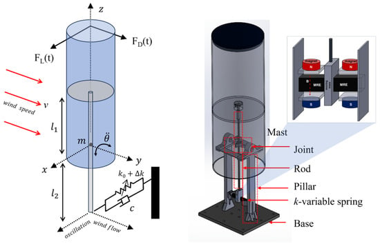
Figure 1.
Overview of the proposed hardware design of the BWT prototype.
When air flows past the cylindrical mast, a periodic, irregular low-pressure vortex is formed at the back of the mast, depending on the Reynolds number. The Reynolds number () characterizes the state of airflow and can be estimated from
where is the air density, v is the air velocity, is the cylinder’s diameter, and is the air viscosity. It is known that a turbulent vortex street occurs around circular cylinders when [23].
The Karman vortex street, which causes fluid pressure differences in the body of the cylinder, results in periodic forces on the cylinder body due to the vortex shedding. The force perpendicular to the air velocity is the lift force and is distributed along the surface. The lift force is assumed to be periodic at the frequency of the vortex-induced vibration (), which depends on the velocity of the air v and the diameter of the cylinder as follows:
where is the lift force coefficient, and is the fluid density [24,25].
The VIV frequency () can be approximated with the Strouhal number (), wind speed (v), and cylinder diameter () according to the following.
where the Strouhal number for a cylinder body is 0.21 over a wide range of wind speeds [4].
When the VIV frequency () due to vortex shedding is close to the structural frequency of the BWT (i.e., ), it causes the resonance of the system to have a maximum magnitude. The range of air velocity ( that causes the resonance of the structure is known as the lock-in range [7] and can be approximated as
Even if the vortex frequency does not precisely match the system frequency, the BWT will still resonate as long as the air velocity is within the lock-in range.
Since the BWT harvests electrical energy from vibration energy, it is preferable to design the structure of the system to resonate under the typical wind speed in the local area. Therefore, the BWT should be designed to closely match the structural frequency to the VIV frequency of the target wind speed.
Typically, a VIV-based BWT is a simple structure of a damped-mass system that has a resonant frequency in terms of
Thus, given the design criteria for the average wind speed and diameter , the mast mass m, the stiffness of the structure k, and the damping c are carefully selected to meet the lock-in condition for the vortex frequency of .
2.2. The Need for System Resonance Tuning
The wind velocity must fall inside the vortex frequency lock-in range in order to yield the most energy from the structural resonance. However, depending on external circumstances, the wind velocity can vary widely and easily go beyond the lock-in range. The overall power conversion efficiency is drastically reduced or even stopped if the wind speed is outside the lock-in range for the BWT.
For example, when the wind speed is at the level of , it closely matches the resonant frequency of the BWT structure () and forces the BWT to vibrate at its highest level, as described in Figure 2. When the wind speed increases to , it is out of the initial lock-in range. Thus, BWT vibration decreases, consequently reducing energy generation, as shown by the red-colored area of the curve in Figure 2.
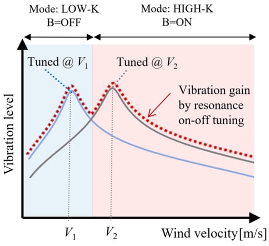
Figure 2.
Conceptual change in the lock-in range and vibration-level gain due to structural resonance tuning in the BWT prototype.
If the BWT can adaptively adjust the resonant frequency of the structure () to match the increased wind speed , the BWT can be in the resonance state again. For such a case, the vibration level would be gained through resonance tuning to obtain higher energy generation efficiency. If the structural resonance can be shifted according to the input wind speed with the different stiffness modes, the vibration gain due to the resonance would be highly maintained, as shown by the dotted curve in Figure 2.
Several solutions have been developed to improve the overall working efficiency of BWTs by incorporating a resonance-tuning system capable of expanding the lock-in range. Accordingly, a permanent magnet-based tuning device is applied in a BWT by Villareeal et al. [4]. As the wind speed increases, the vibration amplitude of the BWT also increases, which draws the two magnets of the same poles closer together. This acts as a compression spring, which exerts a strong repulsive force on the two magnets. Zhang et al. [26] proposed another similar resonance-tuning system using magnetic repulsion force, which varies the relative position of the two magnets for resonance tuning. A different approach is a self-tuning piezoelectric system [27] that uses centrifugal force and drag to adjust the effective beam length in order to tune the resonance of the device.
Previous studies have adopted resonance-tuning systems based on magnetic repulsion or piezoelectric systems. On the other hand, this work proposes a resonance-tuning system with a different approach that utilizes a smart elastomer that can vary its stiffness in response to a magnetic field.
3. Design of a Resonance-Tunable BWT
3.1. BWT Design and System Modeling
The proposed BWT system consists of a cylinder mast, a rigid rod, and a variable-stiffness elastomer, as shown in Figure 1. For this research, the variable-stiffness elastomer is made of magnetorheological elastomers (MREs), a class of smart materials that are widely used for resonance-tuning applications.
When the lift force is exerted by the vortex shedding, the mast oscillates about the pin joint in a direction perpendicular to the force. Although the lift force is distributed along the mast surface, this study assumes that the lift force is exerted as a single-point force at the center point of the mast cylinder, which is denoted as from the joint. Additionally, the shift moment by the center of gravity can be ignored if the mass centroid is designed to be very close to the rotation axis. The reaction forces to the rotation energy by the lifting force are provided by the stiffness () and damping () of the MREs. Note that the MREs provide the equivalent stiffness and damping values of the BWT.
By assuming that the mast and rod are rigidly connected, the structure can be modeled as a first-order mass–spring–damper system that oscillates about the pin joint. Thus, the system dynamics due to the lift force of vortex shedding and the MRE reaction forces are expressed as
where J represents the rotational moment of inertia of the mast, is the point where the lift force is applied, and is the length of the rod from the pin joint. Additionally, the MRE stiffness () is a function of the nominal stiffness and a variable increment by an external magnetic field (B).
Assuming that the mast rotation is small, the shear displacement of the MRE x due to the rod’s oscillation can be approximated as . Then, the BWT dynamics in terms of the displacement x can be expressed using Equation (6) as
The structural resonant frequency of the proposed BWT is calculated using Equations (5) and (8) as a function of the magnetic field.
where is a constant variable of . This equation shows that the structural resonant frequency can be tuned from the nominal state by increasing the MRE stiffness with the amount of .
Due to the vortex-induced vibration, a periodic lift force that oscillates the BWT is generated. The BWT’s vibration motion due to the periodic lift force is converted into the frequency domain to analyze the vibrations for various oscillation periods. Thus, the vibration displacement caused by the lift force in the frequency domain can be derived from Equation (8) as the transfer function of
3.2. Hardware Design Parameters
3.2.1. Mast Design Parameter
The mast is cylindrical in shape, as illustrated in Figure 1. It is made up of a polycarbonate tube with a thickness of 3 mm, which is sufficiently rigid and lightweight. The mast is supported by a rigid stainless steel rod (SUS304) with a diameter of 5 mm and a length of 0.4 m. The rod is pivoted by the pin joint to restrict the BWT’s oscillation to a one-axis direction to simplify the vibration analysis. To reduce the energy loss from friction when the mast vibrated, ball bearings were used in the pin joint, which was located near the center of the rod.
The diameter of the mast and the wind velocity v were established as reference parameters to design the stiffness and resonance of the structure of the system. The mast was a cylinder with a diameter m and a height of 0.4 m, and it was considered for testing using wind tunnel equipment. The total mass of the cylinder mast with the rod and the connecting part was measured to be 1.64 kg. With the lengths and of 0.2 m, the rotational moment of inertia J was calculated to be 0.0738 kg·m2.
3.2.2. VIV Frequency
We selected the target wind velocity of m/s to be close to the average wind velocity of the local area, which is approximately m/s. The concurrent vortex-induced vibration (VIV) frequency is proportional to the wind speed and inversely proportional to the mast diameter, as explained in Equation (11). Setting the mast diameter to 0.15 m, the VIV frequency is calculated as
3.3. Comparison to Conventional BWT
The proposed BWT has a structure similar to that of the conventional vortex BWT system designed in [4], which is composed of a cylindrical mast on an oscillating rod. However, there are crucial differences in their working principles. The proposed system uses a rigid rod to oscillate about the pivot point with a pin joint, whereas other BWTs oscillate using a flexible rod, with one end being fixed to the ground. The stiffness of the proposed BWT is dependent on the elastomer stiffness, whereas conventional BWTs use the stiffness of the flexible rod. Most importantly, the a resonance-tuning module based on a smart material was not applied in previous BWTs.
4. Design of the On–Off Resonance-Tuning Module
4.1. Design Parameters
The proposed resonance-tuning system is based on MREs, which are elastomers with variable stiffness properties that can change the resonance of the BWT structure. The proposed MRE-based resonance-tuning module was designed and connected to the end of the rod, as shown in Figure 3. Two MRE blocks were aligned perpendicular to the direction of the oscillation of the rod to provide shear stiffness. When an external magnetic field was applied to the MREs, the elastomer hardened, which consequently increased the overall stiffness of the BWT structure.
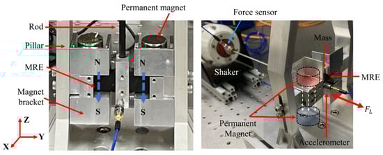
Figure 3.
The proposed resonance-tuning module and experimental setup for the MRE property test.
The magnetic field can be controlled by placing permanent magnets on the magnet brackets that cover the MREs, as shown in Figure 3. The direction of the magnetic field is designed to be vertical so that it does not significantly influence the deformation of the MRE shape. If a horizontal magnetic field along the vibration direction is applied, the flexible MREs bend and stick to the side of the net magnetic field, causing the deformation of the MRE.
The utilized permanent magnet was a Neodymium magnet (NdFeB) with a diameter of 20 mm and a height of 10 mm. The gap between the vertical permanent magnets was 21 mm. At the center point between the magnets, the magnitude of the magnetic field was measured to be 170 mT for mode B = ON. For a state of no magnetic field (B = OFF), the permanent magnets were removed from the bracket. The magnet bracket and base pillars were manufactured with nonmagnetic aluminum materials to minimize the disturbance of the magnetic field lines that passed to the MREs.
4.2. MRE Manufacturing Process
The MREs used in the prototype were prepared by mixing a platinum-catalyzed base silicone (Ecoflex 00-30) and silicone hardener in the same ratio. Then, carbonyl iron particles (CIP 3189, BASF) with a diameter of approximately 3 μm were added to the silicone base with a weight ratio of 50 wt %. After the CIPs were thoroughly and evenly mixed, air bubbles were extracted using a vacuum chamber.
The MRE mixture was poured into a square mold and cured under a strong magnetic field at room temperature for two days. During the curing of the elastomer, it was subjected to a strong magnetic field by placing strong permanent magnets above and below the mold to form the CIP chains.
4.3. MRE Property Analysis
First, the variational properties of the Young modulus, stiffness, and damping of the MREs were analyzed to design the appropriate MREs for application in a BWT. The MREs for the BWT were designed to function for shear stiffness with a thin rectangular shape. Thus, the dimension of the MREs for the property analysis was also a thin rectangle with a length of 14 mm, a height of 10 mm, and a width of 5 mm. Two specimens of MREs in parallel structures were used in this property analysis.
Young’s modulus (E) of the MREs can be derived by using the cantilever formula for MREs of a length L and the area moment of inertia I as
where is the total stiffness of two MREs in parallel, and is the stiffness for each MRE. The area moment of inertia (I) for this MRE is defined using the dimension of the cross-sectional area () while taking the direction of the force into account, as shown in Figure 3. An MRE can be considered a cantilever beam under shear force , and to analyze shear stiffness, a mass of 180 g was attached between the two MRE specimens, and a dynamic load force () was applied in the x-direction, as shown in Figure 3.
The change in the properties of MREs due to a magnetic field is summarized in Table 1. As explained in Section 3.3, the target total stiffness of the MREs was about 570 N/m to tune the BWT at the resonant frequency of Hz. Therefore, using the results in Table 1 and Equation (12), the MREs for the BWT prototype were designed with dimensions of approximately mm, mm, and mm.

Table 1.
The changes in stiffness, Young’s modulus, and damping under a magnetic field for the MRE samples. Two MREs in parallel structures were implemented in the analysis.
5. Experimental Results
A series of experiments were conducted to validate the performance of the MRE-based tuning module in increasing the BWT’s operating range of wind speeds.
5.1. Vibration Test for Resonance Tuning
The first experiment focuses on analyzing the range of changes in the frequency response of the BWT as a result of the change in the stiffness of the MREs. The frequency response function (FRF) of the BWT, which was acquired through a modal vibration test, shows the resonant frequencies of the system. The tuning range performance of the proposed module can be analyzed using the shift in resonant frequencies when a magnetic field is applied to the MREs.
A modal shaker was used to apply a dynamic input force to the BWT in the same direction as the oscillation of the mast rod. The shaker tip was directly connected to the mast via a force sensor. The same amplitude was applied by the shaker to the mast to generate the input force, which was recorded by the force sensor (PCB 208C01). Mast vibration was measured with an accelerometer (PCB 352C66) at a sampling rate of 1 kHz.
The input force was applied as a sine-sweep signal with a frequency range of 0 to 20 Hz over a period of 10 s. The average vibration amplitude was about 3 mm. Only the low-frequency band from 0 to 20 Hz was chosen as the input frequency because the frequency band of interest, such as the VIV frequency and the BWT system frequency, existed within this range. Modal tests under the same conditions were repeated 10 times, and their results were averaged to obtain the frequency response function.
The experiment was repeated on the BWT without and with the external magnetic field applied to the MREs to compare their resonant frequencies. For the case of MREs with a magnetic field (B = ON), permanent magnets were placed on the magnet bracket, and the magnetic field was measured to be 170 mT.
The results of the frequency response function (FRF) experiment on the BWT are plotted in Figure 4. The FRF was calculated as the ratio between the mast body acceleration and the input vibration force in the frequency domain. The first resonance of the BWT without the magnetic field (B = OFF) is observed at a frequency of 2.8 Hz, which is equivalent to 2.0 m/s of wind speed.
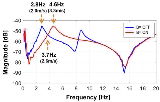
Figure 4.
FRF results for the BWT with a frequency range of 0–20 Hz. The shift of the resonant frequency is observed by applying a magnetic field.
When a magnetic field was applied (B = ON), this first resonance peak was shifted right to 4.6 Hz, equivalent to 3.3 m/s of vortex shedding. The resonant frequency in the first mode increased from 2.8 Hz to 4.6 Hz by 64. 3% as a result of the change in MRE stiffness due to the magnetic field. These results are summarized in Table 2.
Table 2.
The changes in the resonant frequency and the lock-in wind speed of the BWT in different magnetic field modes.
According to the experimental results, the lock-in range for the mast increased by 64.3% with the MRE-based tuning system. The BWT with nominal MREs (0 mT) resonated when the wind speed was around 2.0 m/s with a vortex-shedding frequency of 2.8 Hz. At this wind speed or force frequency, the vibration amplitude of the BWT was comparable to that of the MREs when the MREs did not have a magnetic field applied, as shown in Figure 5. As the wind speed increased, the vibration of the BWT with the nominal MREs gradually decreased. The vibration level of the BWT eventually became lower than that of the magnetic field after the wind speed passed over 2.6 m/s. In comparison, the BWT with MREs under the magnetic field (B = ON) resonated at a higher wind speed of around 3.3 m/s, as shown in Figure 5.
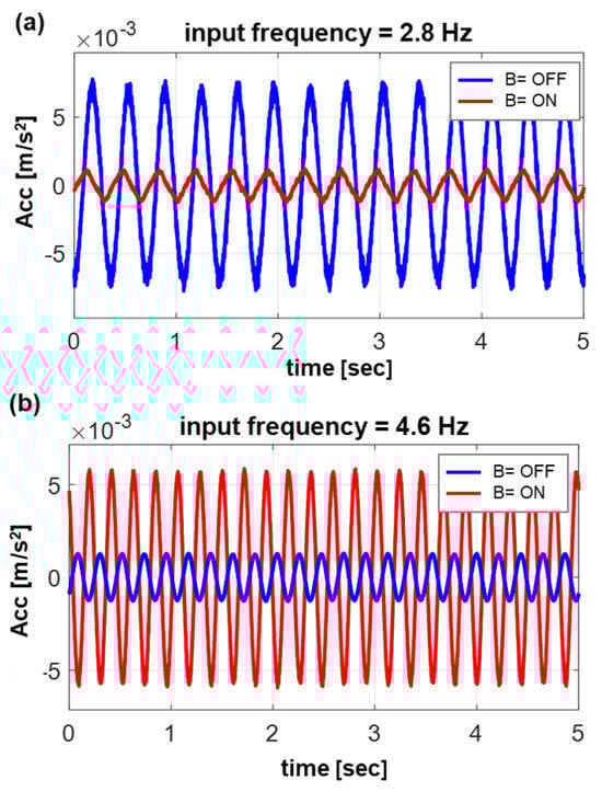
Figure 5.
Comparison of the vibration acceleration of the BWT without and with magnetic field (a) at an input frequency of 2.8 Hz and (b) an input frequency of 4.6 Hz.
5.2. Power Generation Comparison
Since a higher vibration level of the BWT can generate higher power, applying a magnetic field to the MREs when the wind speed is over 2.6 m/s can increase the energy production efficiency. If the wind speed is lower than 2.6 m/s, the BWT should operate in the nominal MRE state to maximize energy harvesting.
To analyze the power generation efficiency for different wind speeds, an electric coil of 1000 loops was used to induce electric current from the BWT’s oscillation.
The distributions of the induced voltage over a range of excitation frequencies for differently tuned BWTs are plotted in Figure 6. According to the voltage–frequency response in Figure 6, the BWT tuned with B = OFF had the highest voltage generation of around 2.6 Hz, and the BWT tuned with B = ON had the highest voltage peak at 4.3 Hz. There was a slight decrement in the overall resonance frequencies because additional mass was attached to the BWT during the power generation test.
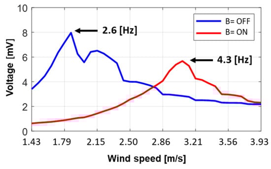
Figure 6.
Comparison of the induced voltage at a wind speed of 3.9 m/s (5.5 Hz) between the nominal BWT and a re-tuned BWT with 170 mT.
When applying a frequency lift force of 2.8 Hz (wind speed of 2.0 m/s), the induced voltage had a root mean square voltage of 6.9 mV, and the vibration energy, the total of kinetic and potential energy, was calculated to be 7.5 mJ. As the frequency of the input excitation increased to 4.6 Hz (wind speed of 3.3 m/s), the induced voltage was reduced to 2.8 mV by a factor of 2.5 times. Also, the vibration energy decreased to 1.8 mJ by a factor of three times. In this mistuned state, the magnetic field was turned on to tune the BWT’s resonance to match the excitation frequency. As expected, the tuned BWT showed higher power generation, which increased the voltage to 5.3 mV by a factor of 1.9 and increased the energy by a factor of 4, as shown in Figure 7 and Table 3.
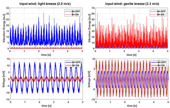
Figure 7.
Comparison of the vibration energy and induced voltage when excited at 2.0 m/s and 3.3 m/s.
Table 3.
Comparison of voltage induction at different velocities in each tuning control mode.
5.3. Wind Tunnel Test
The modal test could not be used to analyze the vibration caused by the force induced by vortex shedding, which has a direction perpendicular to the wind velocity. In the modal test, the input force was in the same direction as the BWT’s vibration, since the modal shaker was physically connected to the mast. Thus, a second experiment was conducted with wind tunnel equipment to analyze the resonance of the BWT as a result of the vortex shedding at a wide range of wind velocities.
The BWT prototype was placed in front of the wind tunnel equipment, as shown in Figure 8. The direction of the BWT’s mast oscillation was set to be perpendicular to the wind velocity. The wind generated by the equipment was blown onto the BWT to induce vortex-shedding vibration, which oscillated the BWT’s mast. The wind speed was controlled from 1.6 to 3.6 m/s with an interval of 0.2 m/s. An anemometer was installed near the BWT to record the input wind velocity. For each wind speed, the vibration level of the mast was acquired with an accelerometer at a sampling rate of 1 kHz for 10 s. The experiment was repeated for the BWT without and with the magnetic field applied for the comparison. The root mean square (RMS) of the acceleration was normalized by the lift force for an index metric of the BWT’s vibration. The vibration results of the BWT against various wind velocities and different magnetic field levels are plotted in Figure 9.
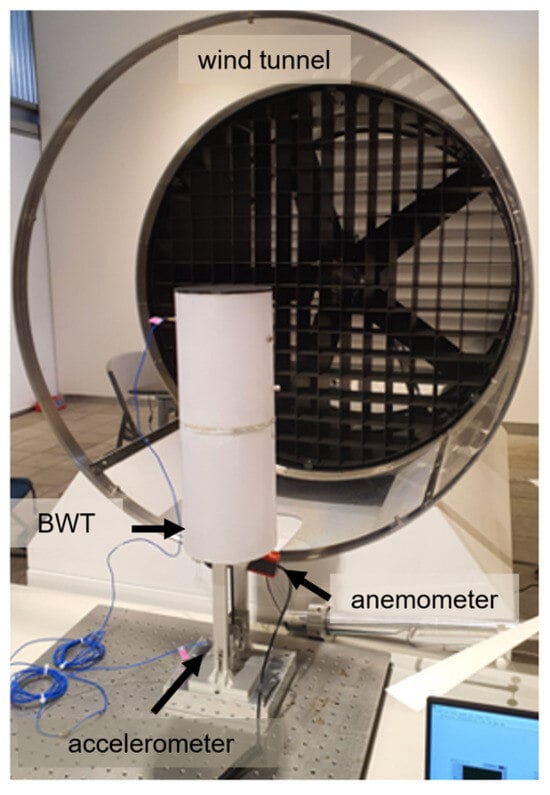
Figure 8.
Experimental setup for the wind tunnel equipment.
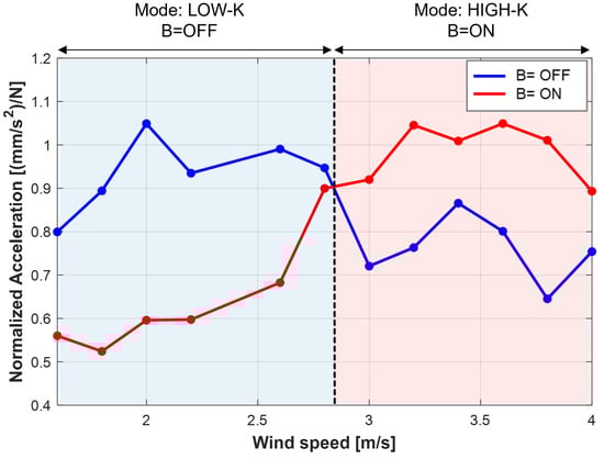
Figure 9.
Comparison of the BWT’s vibration energy against the wind speed for different MRE stiffnesses. For a wind speed higher than 2.8 m/s, applying a magnetic field to the MREs generated higher vibration energy.
According to the experimental results, the BWT with the nominal MRE state (B = OFF) in the Low-K mode had a higher oscillation energy against a wind speed lower than 2.8 m/s. When the wind speed was higher than 2.8 m/s, the BWT could oscillate more if a magnetic field was applied to the MREs (B = ON). In Figure 10, the acceleration and frequency spectrum of the BWT with different MRE states are compared at wind speeds of 2.0 and 3.2 m/s.
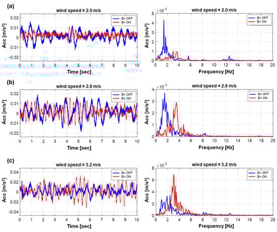
Figure 10.
Frequency and time response of the BWT with and without an applied magnetic field. The wind speed was 2.0 m/s–3.2 m/s.
It can be concluded that for low-wind-speed conditions, the BWT should operate in the nominal state. For weather conditions with higher wind speeds, a magnetic field should be applied to maximize the mast oscillations for more efficient energy harvesting. This crossing point at 2.8 m/s was similar to the value observed in the vibration curve in Figure 4, which was 2.6 m/s. This difference was mainly due to the differences in the experimental setup and the input force conditions. The wind speed of the wind tunnel was not perfectly uniform on the BWT’s mast. Additionally, there was a wind gradient on the mast surface along the direction of the vertical axis. Thus, the vortex-shedding frequency was not purely sinusoidal in the wind tunnel test, as in the modal test. However, the trend of the vibration-level curves when applying the magnetic field was similar in both the wind tunnel and the modal test results.
In summary, a higher vibration of the BWT can be maintained for a higher wind velocity by applying a magnetic field. Thus, the proposed MRE-based tuning system can widen the lock-in range of the BWT for efficient energy harvesting.
5.4. Shortcomings and Future Improvements
The proposed resonance module has only an on–off mode that maintains either a low stiffness or a high stiffness. Furthermore, the purpose of the study was to analyze the feasibility and the performance of the proposed system in a manually controlled mode. In future work, an automated magnetic field controller needs to be designed to generate a continuous magnetic field.
Although the smart elastomer is effective in changing the stiffness, it has an inherent damping effect that limits high-resonance vibrations. There was an increase in the damping of the elastomer by 27% under a magnetic field, but this was a much smaller change than the stiffness change ratio, which was 152%. However, there should be a more in-depth study of the effect of the damping of this smart elastomer.
6. Conclusions
This study proposed an MRE-based resonance-tuning module for a small-scale bladeless wind turbine (BWT) that can improve energy generation efficiency by widening the air velocity resonance operation range. MREs act as variable-stiffness elastomers that can increase a BWT’s resonant frequency when a magnetic field is exerted on them. A series of experiments were conducted to analyze the performance of the MRE-based tuning module in increasing the BWT’s operating range. The vibration experiment showed that the designed tuning module could shift the BWT’s resonance from 2.8 to 4.6 Hz by 64.3% when a magnetic field of 170 mT was applied. The wind tunnel test showed that the BWT prototype resonated when the wind speed was lower than 2.8 m/s. When the wind speed was higher than 2.8 m/s, the BWT could oscillate more by increasing the stiffness of the MREs. This re-tuning of the BWT could increase the power generation by as much as 1.9 times. Also, by controlling the MRE stiffness, the BWT can have a wider lock-in range for resonance to operate in a wider range of wind velocities.
In future work, a power-efficient magnetic field generator should be designed to control the MRE stiffness. This generator must consume less power than the energy generated by the BWT. Furthermore, BWTs should be optimally designed to enhance energy generation, and the degrees of freedom of oscillation should be expanded to cover other wind directions.
Author Contributions
Conceptualization, H.K. and Y.-K.K.; methodology, H.K., J.K., and Y.-K.K.; writing—original draft, H.K. and J.K.; writing—review and editing, Y.-K.K.; project administration, J.L. All authors have read and agreed to the published version of the manuscript.
Funding
This study was supported by a grant from the National Research Foundation of Korea (NRF) funded by the Ministry of Education (No. 2020R1I1A3074036), and it was partly supported by a grant from the Korea Institute of Energy Technology Evaluation and Planning (KETEP) funded by the Ministry of Trade, Industry, and Energy (MOTIE) of the Republic of Korea (No. 20214000000010).
Institutional Review Board Statement
Not applicable.
Informed Consent Statement
Not applicable.
Data Availability Statement
The data presented in this study are available upon request from the corresponding author.
Conflicts of Interest
We declare that we have no financial or personal relationships with other people or organizations that can inappropriately influence our work. There is no professional or other personal interest of any nature or kind in any product, service, and/or company that could be construed as influencing the position presented in the review of this manuscript.
References
- Premalatha, M.; Abbasi, T.; Abbasi, S.A. Wind energy: Increasing deployment, rising environmental concerns. Renew. Sustain. Energy Rev. 2014, 31, 270–288. [Google Scholar]
- Everaert, J.; Stienen, E.W. Impact of wind turbines on birds in Zeebrugge (Belgium). In Biodiversity and Conservation in Europe; Springer: Berlin/Heidelberg, Germany, 2006; pp. 103–117. [Google Scholar]
- El-Shahat, A.; Keys, D.; Ajala, L.; Haddad, R.J. Bladeless wind turbine (case study). In Proceedings of the 2019 SoutheastCon, Huntsville, AL, USA, 11–14 April 2019; IEEE: Piscataway, NJ, USA, 2019; pp. 1–5. [Google Scholar]
- Villarreal, D.Y.; Sl, V.B.; VIV Resonant Wind Generators. Vortex Blade-Less SL. 2018. Available online: https://vortexbladeless.com (accessed on 1 March 2024).
- Gabbai, R.D.; Benaroya, H. An overview of modeling and experiments of vortex-induced vibration of circular cylinders. J. Sound Vib. 2005, 282, 575–616. [Google Scholar] [CrossRef]
- Chizfahm, A.; Yazdi, E.A.; Eghtesad, M. Dynamic modeling of vortex induced vibration wind turbines. Renew. Energy 2018, 121, 632–643. [Google Scholar] [CrossRef]
- Bourguet, R.; Karniadakis, G.E.; Triantafyllou, M.S. Lock-in of the vortex-induced vibrations of a long tensioned beam in shear flow. J. Fluids Struct. 2011, 27, 838–847. [Google Scholar] [CrossRef]
- Hu, G.; Tse, K.T.; Kwok, K.C.S.; Song, J.; Lyu, Y. Aerodynamic modification to a circular cylinder to enhance the piezoelectric wind energy harvesting. Appl. Phys. Lett. 2016, 109, 193902. [Google Scholar] [CrossRef]
- Ding, L.; Yang, L.; Yang, Z.; Zhang, L.; Wu, C.; Yan, B. Performance improvement of aeroelastic energy harvesters with two symmetrical fin-shaped rods. J. Wind Eng. Ind. Aerodyn. 2020, 196, 104051. [Google Scholar] [CrossRef]
- Chang, C.C.J.; Kumar, R.A.; Bernitsas, M.M. VIV and galloping of single circular cylinder with surface roughness at 3.0 × 10⁴ Re 1.2 × 10⁵. Ocean Eng. 2011, 38, 1713–1732. [Google Scholar] [CrossRef]
- Roman, M.; Sobh, R.; Sedrak, M.; Ali, M. Power performance enhancement of vortex-induced vibration wind turbines using a semi-active control approach. Energy Sources Part A Recovery Util. Environ. Eff. 2021, 1–19. [Google Scholar] [CrossRef]
- Bahri, Z.S.; Barday, W.; Ez-Zabri, S.; Salih-Alj, Y. Design Considerations of a Hybrid Piezoelectric-Electromagnetic Tuning System for Vortex Induced Vibration Bladeless Turbines: Morocco Case Study. In Proceedings of the 2022 IEEE International Conference on Mechatronics and Automation (ICMA), Guilin, China, 7–10 August 2022; IEEE: Piscataway, NJ, USA, 2022; pp. 611–616. [Google Scholar]
- Ayala-Garcia, I.; Mitcheson, P.; Yeatman, E.; Zhu, D.; Tudor, J.; Beeby, S. Magnetic tuning of a kinetic energy harvester using variable reluctance. Sens. Actuators A Phys. 2013, 189, 266–275. [Google Scholar] [CrossRef]
- Bahadur, I. Dynamic Modeling and Investigation of a Tunable Vortex Bladeless Wind Turbine. Energies 2022, 15, 6773. [Google Scholar] [CrossRef]
- Kuder, I.K.; Arrieta, A.F.; Raither, W.E.; Ermanni, P. Variable stiffness material and structural concepts for morphing applications. Prog. Aerosp. Sci. 2013, 63, 33–55. [Google Scholar] [CrossRef]
- Jolly, M.R.; Carlson, J.D.; Muñoz, B.C.; Bullions, T.A. The magnetoviscoelastic response of elastomer composites consisting of ferrous particles embedded in a polymer matrix. J. Intell. Mater. Syst. Struct. 1996, 7, 613–622. [Google Scholar] [CrossRef]
- Yang, C.; Fu, J.; Yu, M.; Zheng, X.; Ju, B. A new magnetorheological elastomer isolator in shear–compression mixed mode. J. Intell. Mater. Syst. Struct. 2015, 26, 1290–1300. [Google Scholar] [CrossRef]
- Ginder, J.M.; Nichols, M.E.; Elie, L.D.; Clark, S.M. Controllable-stiffness components based on magnetorheological elastomers. In Proceedings of the Smart Structures and Materials 2000: Smart Structures and Integrated Systems, Newport Beach, CA, USA, 6–9 March 2000; SPIE: Bellingham, WA, USA, 2000; Volume 3985, pp. 418–425. [Google Scholar]
- Lee, K.H.; Park, J.E.; Kim, Y.K. Design of a stiffness variable flexible coupling using magnetorheological elastomer for torsional vibration reduction. J. Intell. Mater. Syst. Struct. 2019, 30, 2212–2221. [Google Scholar] [CrossRef]
- Kim, Y.K.; Bae, H.I.; Koo, J.H.; Kim, K.S.; Kim, S. Note: Real time control of a tunable vibration absorber based on magnetorheological elastomer for suppressing tonal vibrations. Rev. Sci. Instrum. 2012, 83, 046108. [Google Scholar] [CrossRef]
- Kim, Y.K.; Koo, J.; Kim, K.S.; Kim, S. Suppressing harmonic vibrations of a miniature cryogenic cooler using an adaptive tunable vibration absorber based on magneto-rheological elastomers. Rev. Sci. Instrum. 2011, 82, 035103. [Google Scholar] [CrossRef]
- Jang, D.I.; Yun, G.E.; Park, J.E.; Kim, Y.K. Designing an attachable and power-efficient all-in-one module of a tunable vibration absorber based on magnetorheological elastomer. Smart Mater. Struct. 2018, 27, 085009. [Google Scholar] [CrossRef]
- Dalton, C. Fundamentals of Vortex Induced Vibration; University of Houston: Houston, TX, USA, 2013. [Google Scholar]
- Sassi, P.; Freiría, J.; Mendina, M.; Draper, M.; Usera, G. Simulation of vorticity wind turbines. Heliyon 2020, 6, e05155. [Google Scholar] [CrossRef]
- Saengsaen, S.; Chantharasenawong, C.; Wu, T.L. A 2–d mathematical model of vortex induced vibration driven bladeless wind turbine. MATEC Web Conf. 2019, 291, 02007. [Google Scholar] [CrossRef][Green Version]
- Zhang, L.; Abdelkefi, A.; Dai, H.; Naseer, R.; Wang, L. Design and experimental analysis of broadband energy harvesting from vortex-induced vibrations. J. Sound Vib. 2017, 408, 210–219. [Google Scholar] [CrossRef]
- Sun, W.; Seok, J. A novel self-tuning wind energy harvester with a slidable bluff body using vortex-induced vibration. Energy Convers. Manag. 2020, 205, 112472. [Google Scholar] [CrossRef]


Disclaimer/Publisher’s Note: The statements, opinions and data contained in all publications are solely those of the individual author(s) and contributor(s) and not of MDPI and/or the editor(s). MDPI and/or the editor(s) disclaim responsibility for any injury to people or property resulting from any ideas, methods, instructions or products referred to in the content. |
© 2024 by the authors. Licensee MDPI, Basel, Switzerland. This article is an open access article distributed under the terms and conditions of the Creative Commons Attribution (CC BY) license (https://creativecommons.org/licenses/by/4.0/).