Abstract
A faulty voltage measurement can lead to the overcharging of a Li-Ion cell, resulting in gas formation and heating inside the cell, which can trigger thermal runaway. To mitigate this risk, cylindrical cells are equipped with a Current Interrupt Device (CID), which functions as a pressure relief valve, disconnecting the electrical circuit within the cell when internal pressure rises. However, this disconnection causes the cell to suddenly become highly resistant, posing a significant issue in series-connected cells. In such configurations, a portion or even the entire system voltage may drop across the disconnected cell, substantially increasing the likelihood of an electric arc. This arc could ignite any escaping flammable gases, leading to catastrophic failures. In a series of tests conducted on three different cell chemistries—NMC (Nickel Manganese Cobalt), NCA (Nickel Cobalt Aluminum), and LFP (Lithium Iron Phosphate)—it was found that the safe operation of the CID cannot be guaranteed for system voltages exceeding 120 V. Although comparative tests at double the nominal cell voltage did not exhibit the same behavior, these findings suggest that current safety standards, which recommend testing at double the nominal voltage, may not adequately address the risks involved. The tests further revealed that series connections of cells with CIDs are inherently dangerous, as, in the worst-case scenario, the entire system voltage can be concentrated across a single cell, leading to potential system failure.
1. Introduction
With the advancement in electrical and electronic engineering, our modern lifestyles are highly influenced and dependent on devices such as smartphones, tablet computers, E-bikes, Electric Vehicles (EV), power tools, and even home energy storage systems. According to the IEC 61140 standard [1], these devices can be categorized into two voltage levels [1], devices with a voltage less than 60 V AC and 120 V DC and devices with voltage-range up to 1000 V AC and 1500 V DC [1]. The primary category consists of devices such as power tools, E-bikes, laptops, and cell phones. These devices are usually considered to be safe due to their extra-low voltage, i.e., at this voltage level, the items are not considered to be fatal to an adult under normal conditions [1]. The latter category is also known as so-called low-voltage range devices, such as EVs with nominal voltage levels from 400 V DC to 800 V DC. This application acquires the required operating electrical energy from a Lithium-Ion (Li-Ion) cell, with a maximum cell voltage of 4.2 V [2]. In general, this voltage level is sufficient for a smartphone, but to run an E-bike (36 V DC) [3] and EV (400 V DC), almost 10 and 96 cells are connected in series, respectively. Such an increased number of cells also creates greater complexity in the system, as each cell should be operated in its safe operating conditions, i.e., each cell should operate within the manufacturer-defined current, voltage, and temperature limits. Li-Ion cells react particularly critically to overcharging, as this leads to gas formation inside the cell [4]. Therefore, to make sure that each cell is operating within its correct range, a Battery Management System (BMS) is used in the battery. BMS monitors these parameters and ranges to ensure cells are operating in appropriate conditions. For example, without BMS, the Li-Ion cells are highly susceptible to overcharging and can lead to gas formation within the cell, which consequently causes a thermal runaway. However, the benefits of using BMS is that it disconnects the cell and/or battery in the event of such faults and prevents such critical situations [5]. In addition to BMS, cylindrical cells are also equipped with passive safety system such as a Current Interrupt Device (CID). A CID is installed in cells to ensure the safety of the battery module [6]. The purpose of a CID is to disconnect the cell internally in the event of gas formation caused by decomposition reactions and the pressure within the cell is increased. Such events occur due to excessively high temperatures or overcharging. However, due to the opening of CID, the potential risk of an electrical arc rises [7], which leads to the question of whether a cell with a CID used in a series connection is hazardous or not. For example, an EV with a 400 V system could have some technical issue that may lead to a very high voltage in a single cell, i.e., a voltage higher than twice of the nominal voltage as suggested by the FreedomCAR [8] standard; in such a scenario, the testing performed at the time of the approval of the EV battery is pointless because having a CID in such scenario could lead towards a dangerous situation [8,9]. To find an optimal answer to this question, numerous tests were carried out in this research at different voltage levels that are often used in EV and Hybrid Electric Vehicles (HEV) applications, i.e., voltages ranging from 120 V DC to 800 V DC.
2. Theoretical Background
Overcharging is one of the most critical situations in battery applications. According to [10], the consequences of overcharging the cells are much more critical compared to deep discharging. Overcharging can cause undesirable side reactions such as the decomposition of the electrolyte, cathode material, and reactions of the electrode with other cell components, which can consequently lead to catastrophic cell failure, like a fire or explosion. There are various reasons for cell overcharging, i.e., a defective charge controller or a faulty BMS. False voltage measurement (measured voltage against actual voltage) can also contribute to cell overcharging. For example, if the BMS has an integrated balancing circuit to monitor the cell voltage, the BMS will try to balance the cell based on faulty voltage values and will eventually overcharge the cell, leading to a potential thermal runaway of the cell. The extent of the thermal runaway depends on the composition of the cells and the resulting chemical reactions inside [11]. Depending on the materials and chemicals used in the cell, oxygen is produced during the decomposition of the cathode (depending on the State of Charge (SOC) and cathode material) [12]. The oxygen reacts with Carbon and the electrolyte solvent which leads to the release of flammable gases like Carbon Monoxide (CO), Carbon dioxide (CO2), and Hydrogen (H2). In such scenarios, Lithium Nickel Manganese Cobalt electrodes (NMC 622 and NMC 811) and Lithium Nickel Cobalt Aluminum electrodes (NCA) behave critically, while the Lithium Iron Phosphate electrode is known as the safest material due to its low release of toxic CO [12] gas. An electrolyte is the primarily responsible element for the gas development in the cell [13]. The gas formation in each cell builds high pressure, and [13] due to the hermetic sealing of Li-Ion cells to the environment, the produced gases escape. Together with the stable metallic outer shell, the gas pressure can go up to 20 bar, and in an uncontrolled event of failure, these gases can explode [6]. To reduce such potential hazards of energy storage devices, various safety devices and control mechanisms are employed. These act both at the cell level and at the system level and serve primarily to prevent abnormal operating conditions such as overcharging of the cells. At the cell level, internal safety measures such as the Positive Temperature Coefficient (PTC) device and the Current Interrupt Device (CID) [6] are adopted. On the system side, BMS is implemented as an external safety measure to monitor the cells continuously. If something goes wrong, it will disconnect the cells from the load or power supply. The PTC is a small metal part integrated at the positive pole, with a Positive Temperature Coefficient, which means that at the time of heating, the PTC increases its resistance and reduces the current flow [7].
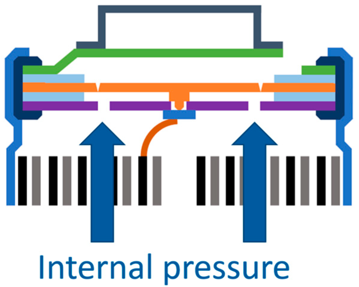
The CID consists of two components, (i) the top disk (orange components in Figure 1) and (ii) the bottom disk (dark blue components in Figure 1). The top disk is a flexible, ring-shaped conductor connected to the bottom disk by a weld in the center of the top disk. Both disks are separated from each other by insulation. Thus, the welded connection between the top and bottom disk is the only electrical connection to the active material, i.e., this represents a weak point in the current path. The top disk is connected to the jelly roll (gray component in Figure 1) by a bottom disk. The light blue areas are plastic insulation, and at the top is the plus pole for external connection to a load or power supply [6].
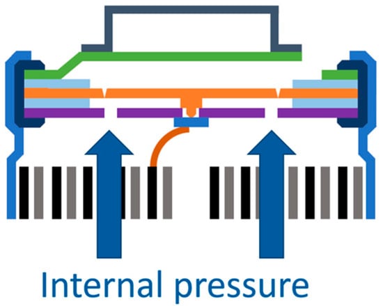
Figure 1.
Current Interrupt Device before opening, with a representation of the components of the part [6].
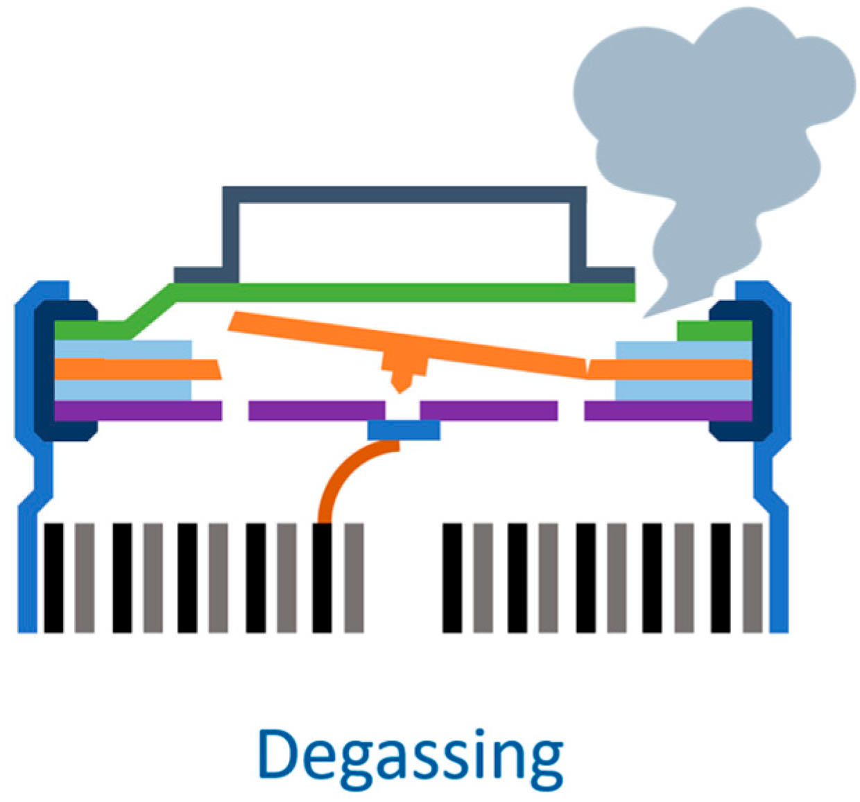
In the event of overcharging and a resulting increase in pressure inside the cell, this structure causes the top disk to bend upwards and causes the weld joint to break mechanically from the metal foil, severing the contact and thus the current path to the active material (see Figure 2).
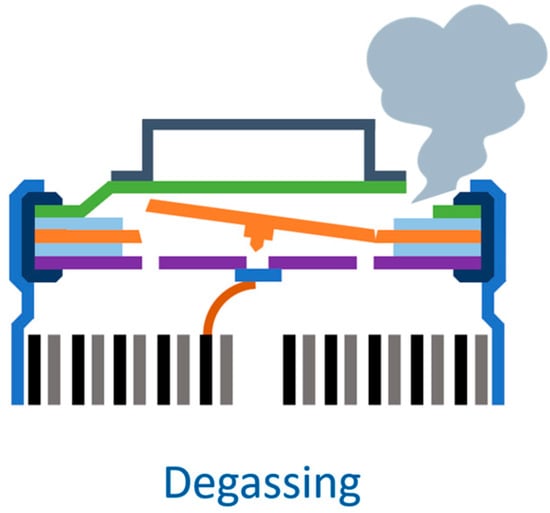
Figure 2.
Current Interrupt Device during the disconnection, with a schematic representation of degassing process [6].
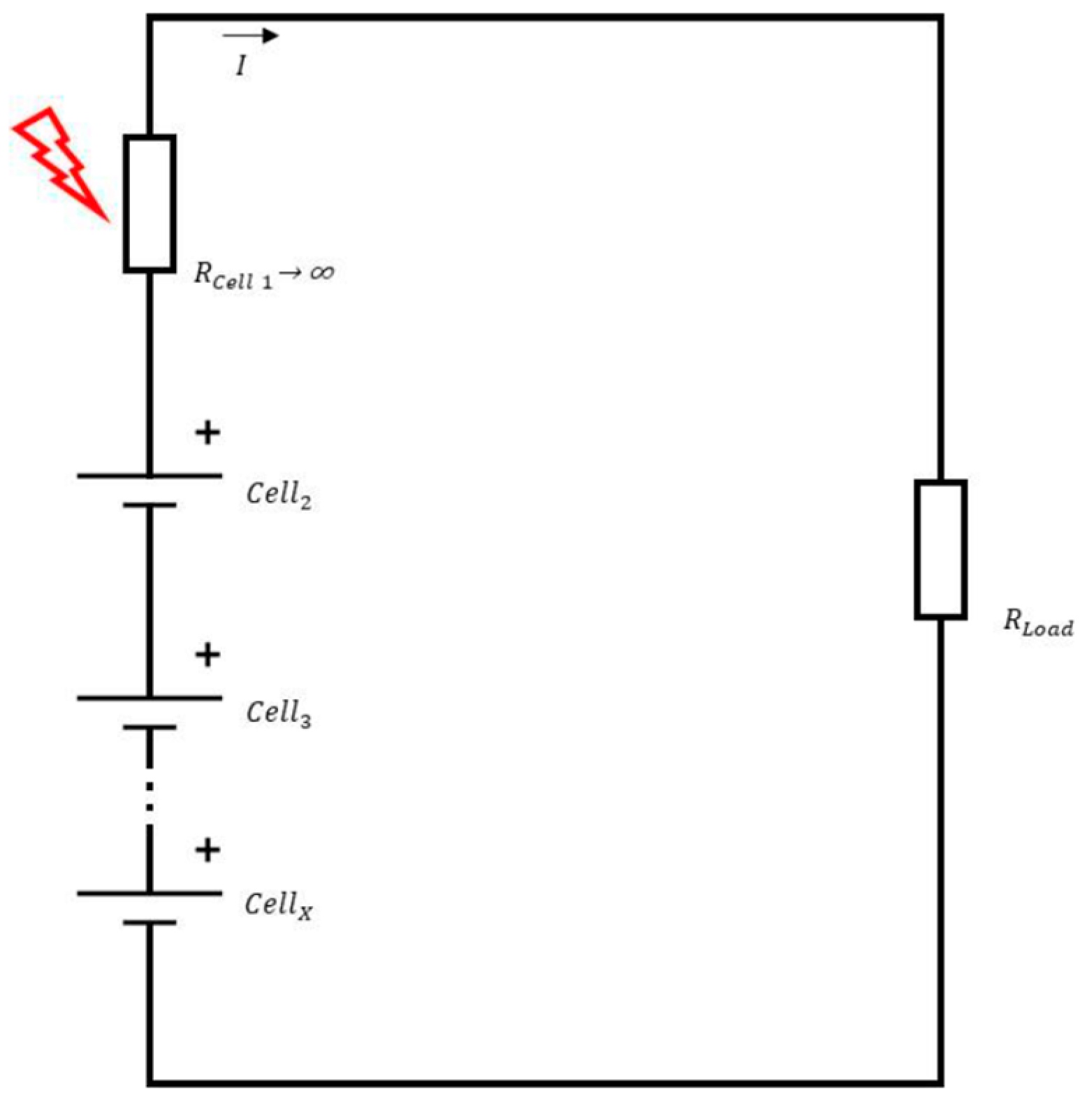
Triggering the CID is comparable to opening a switch under load [7]. When opening current-carrying connections, an electric arc may ignite [14]. This can be transferred to the CID of a cell, which carries the current flow from the cell windings to the positive terminal. Higher voltages are responsible for the formation of electric arcs. For cylindrical cells with CID, a voltage of 18 V is sufficient to generate an electric arc (according to [7]). A single cylindrical cell will not reach such a high voltage value, but it can occur in series connections (see Figure 3).

Figure 3.
Example circuit for an CID opening in cell inside battery system. The complete systems voltage will drop at a cell whose internal resistance is high due to the opening of a CID or overcharge protection additive [15].
If the CID opens on one cell in the circuit, it becomes highly resistive, while the resistances of the other cells remain low, which would drop a large part of the voltage at this cell [15]. This is particularly dangerous when the battery is in a charging state and an external voltage source is connected. However, in such a case, the main question is if there is a potential risk of using cylindrical cells with CIDs in serial connections, which leads to subsequent questions of whether the test standards like the ECR R 100 [16], the ISO12405 [17], UN38.3 [18], and the FreedomCAR [8] cover this problem.
One of the regulations that is significantly important for cell testing is the UN recommendations on the Transport of Dangerous Goods. The recommendations in this document are based on several national laws and international agreements [18]. It is divided into two parts, (i) the Model Regulations and (ii) the Manual of Tests and Criteria. The latter part is important for this research as it encapsulates the information about cell testing and provides information about tests to ascertain the hazards of dangerous goods including battery cells. Newly developed cells must pass special tests before they are allowed to be transported.
Multiple test requirements are outlined in section UN 38.3 T3 [18], which must be carried out by the manufacturer or a testing laboratory [5]. These correspond to the same principle and are carried out as follows. Test T.7 is an overcharge test from the UN standard [18]. Due to the electrolyte’s decomposition at voltages above 4.2 V, increased gas production happens in overvoltage situations [10]. This leads to overpressure inside the cell and to the opening of the CID (see Figure 4). To determine whether the cells will act dangerously in this abuse case, the overvoltage test T.7 is used. The intention of the test is as follows: ‘This test evaluates the ability of a rechargeable battery or a single cell rechargeable battery to withstand an overcharge condition’ [19]. Therefore, the cell should be overcharged to a voltage level of two times the maximum charge voltage. For instance, a cell that can withstand a charge of 4.2 V will be overcharged to 8.4 V. The test will be performed under ambient temperature and with twice the cell data sheet’s maximum continuous charge current [19]. If the cell does not disassemble or catch fire during the 24 h test, it fulfills the criteria. Regulation No. 100 of the UNECE is the legal binding for the approval of EVs in the European Union (EU). One of the tests that this regulation describes is the overcharging test for EV batteries to protect the battery from overcharging. To undertake this test, all active safety functions are activated and the charge control limits of the Device Under Test (DUT) must be deactivated. To pass the test, the battery must stop the current flow when it reaches the maximum charge voltage. If the active safety functions do not stop the charging, the test is over when the battery reaches the double nominal capacity [1]. To obtain the ISO 6469-1:2019 [19] certification, an overcharge test is vital. To undertake the overcharge tests, the battery/DUT is previously charged to the maximum voltage with all active safety functions and the cooling system. The test ends when one of the protection functions stops the current flow, the charge continues for 12 h, the temperature falls 2 K within 1 h, the temperature exceeds an upper limit, or general safety requirements are violated [18]. Another important standard in the field of abuse testing is the FreedomCAR electrical energy storage system abuse test manual for electric and hybrid electric vehicle application standards. For the overcharge test, as per this standard, a constant Direct Current (DC) charging current is used. The maximum charge current can be selected according to the cell data sheets and the test is carried out under normal operating conditions at an ambient temperature of 20 ± 10 °C [19]. The voltage should be set to double the normal voltage [8]. If the cell does not dissemble, the test ends when the cell reaches the double nominal voltage [8]. These criteria do not always correspond to the requirements in real applications because the cells are installed in a module connected in series, e.g., 100 cells forming a 400 V battery system or 200 cells forming an 800 V battery system [20]. Depending on the system, higher voltages can be present. It is important to note here that with the increasing voltages, the risk of electric arcs also increases during the CID opening, as explained in Section 1.

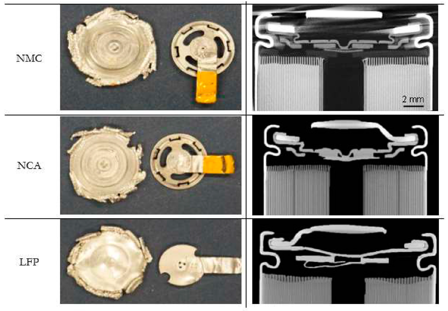
Figure 4.
CT-Scans of the different 18,650 cells, which are different in the positive active materials and CIDs.
3. Experimental Section
To undertake the comparative behavioral analysis in an overcharge test, three different cell chemistries named Lithium Iron Phosphate cell (LFP), Nickel Manganese Cobalt oxide (NMC), and Lithium Nickel Cobalt Aluminum (NCA) were used in this experimental research. This is because LFP is known to react mildly to overcharging [5], NMC electrode is used as cathode material, a more reactive material, and NCA oxide releases oxygen and causes a thermal runaway [5]. The selection of the cells was based on the main criteria that the cells should have a CID, and to ensure this, a sample of each cell type was opened before the start of the experiment. Table 1 describes the basic overview of the cells used in this research.

Table 1.
Overview of the cells used in the experiment.
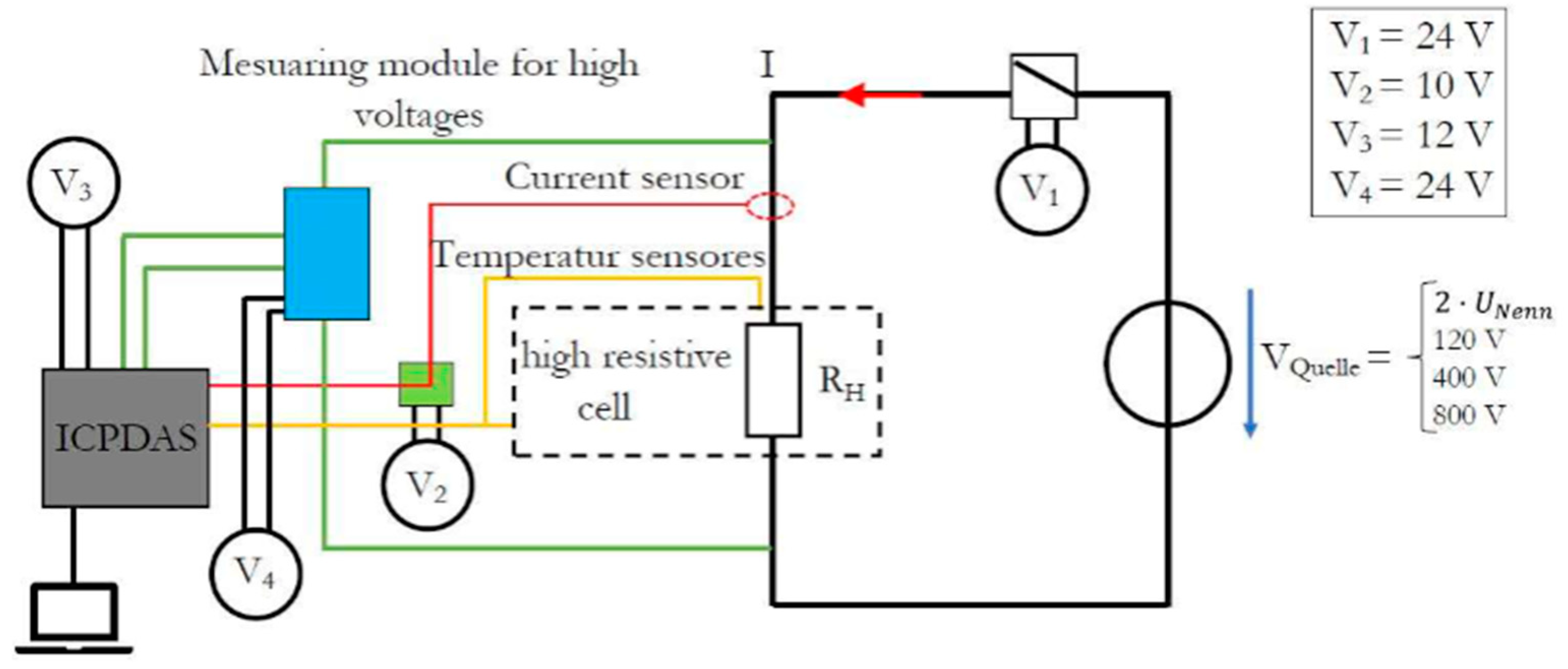
The test setup consisted of a power circuit and a measurement circuit. The measuring circuit is shown in the left half of Figure 5. It included a measuring module for the acquisition of high voltages (DNM-843VI-800V), a current clamp together with an associated measuring module for the measurement of the charging current (DNM-844-50A), and two temperature sensors of Type K. Also, Figure 5 displays the ICPDAS measurement device (from Hukou Township, Taiwan) as the central interface of the data acquisition to the laptop with the installed software “Modbus Utility V1.9.0” for data logging. The current sensor and voltage measuring module were powered by laboratory power sources (Manson NRP-2050 from Hong Kong, China). Furthermore, laboratory power sources (Manson NRP-2050) were used to supply the current sensor, the voltage measurement module, and the data acquisition unit from the IPCDAS. To save the data in a text file and to control the measuring system, the Modbus Utility software for the IPCDAS was installed on a separate laptop. The measuring module and the laptop communicate via an Ethernet interface. To accurately record the separation behavior of the CID, the recording frequency of the measurement data was set to 10 Hz. The overcharge tests were carried out under normal operating conditions [16]. The power circuit consisted of a voltage source (Gwinstek PSW 800-4.32 from New-Taipeh, Taiwan), a load contactor (Tyco Electronics LEV200 from Berwyn, IL, USA), and the cell itself. The Direct Current (DC) voltage source is represented by the power supply unit, which can provide a maximum output voltage of 800 V DC or a maximum charging current of 4.32 A [5]. For safe switching of the voltages or currents, the single-pole power contactor was used, which can handle these high voltages. The overcharging abuse tests were conducted at an outdoor test facility because under such abnormal operating conditions, the Li-Ion cells can catch fire or even explode, which represents high hazard potential [5].

Figure 5.
Test setup. V1–V4 represent voltage sources for supplying the measuring devices.
The rest of the measurement setup consisted of a regular high-definition camera and an infrared camera. Both were placed around ten meters away from the actual test setup to record the events, including the heating process from the cell during the thermal runaway. The tests were carried out based on the FreedomCAR test specifications but under the normal operating temperature of the cell [8], i.e., the ambient temperature at the outdoor test facility. The test device was charged two times the rated voltage level, as defined in the FreedomCAR. The data acquisition was stopped after 30 min, independent of the status of the cell reaction. This was the biggest difference between the actual conducted test against the specification mentioned in the FreedomCAR test manual, i.e., a data recording period of 4 h [8]. The reaction of the cells was evaluated using EUCAR hazard levels [8], as it is the common classification of Li-Ion cells under abnormal operating conditions for evaluating the overcharging behavior [8]. The behavior of Li-Ion cells in abuse tests is subdivided into a total of eight hazard levels [8]. While the activation of the CID can be assigned to hazard level 2 and the blowing-off gases can be assigned to level 3 or 4, depending on the escaped mass of the electrolyte [8].
An ignition of the escaping gases or of the individual cell itself is classified in level 5, a mechanical rupture of the housing in level 6, and an explosion of the cell finally in hazard level 7. The latter behavior represents the most dangerous state of the single cell in the context of an overload test [8]. For further deeper analyses with IBM SPSS V29.0.0(software used for statistical analysis of the recorded data), three color levels regarding the safety behavior of a cell are defined. Hazard levels 0 to 3 are defined as safety status green, while level 4 is yellow and levels 5 to 7 are red. Yellow and red are unsafe conditions. Moreover, for the binary logistic regression, it was necessary to have only two conditions, i.e., safe, and unsafe.
To evaluate the results thoroughly, ten tests per cell, along with different voltage levels (120 V, 400 V and 800 V), were performed. The reason for such voltage levels is because the majority of available EVs are within these levels. A comparison was made between the higher voltage levels and the double nominal voltage taken from the FreedomCar overcharge test to check whether the hazard is directly proportional to the voltage, i.e., increasing the voltage increases the hazard as well.
Before the tests, all cells (see Table 2) were brought to 100% SOC. For this purpose, the cells were charged in the laboratory using cell cycling devices until the cells reached their final charging voltage. Fully charged cells were then brought to the test site for abuse tests.
Table 2.
Number of cells per voltage level.
The FreedomCar overcharge test defines that the current should be set at 32 A [8] for EV tests. However, if the tests are performed at less than pack level, the current must be scaled down [8]. Therefore, for this test series, the current level (refer to Table 3) for each type of cell was selected according to the manufacturer cell datasheet. For the NCA and the NMC cell, the current was set to 4 A. This was limited by the maximum current of the Gwinstek PSW 800-4.32 power supply. Both cells can handle potentially higher continuous currents. In the case of the maximum continuous charge, the current was 1.5 A, according to the datasheet. The cell was charged until the CID interrupted the charge flow or the test was terminated. Each test in the series was carried out for 30 min, regardless of how the cell performed, i.e., irrespective of whether the cell had a thermal runaway or not.
Table 3.
Electrical parameters of the abuse test.
During the statistical evaluation of data by SPSS software, the focus was on the safety of the cells, based on the binary expression “safe” or “unsafe”, which were defined for the target variable in the context of this statistical investigation. There are various statistical models to explain a target variable (here the expression “safe” or “unsafe”) by several other variables and to safeguard the relationship against random fluctuations. The most used model is regression analysis, in which the coefficients of a functional relationship (including linear, quadratic, cubic, or exponential) between the independent and dependent variables are estimated from the data and their significance is verified. Due to the discrete nature of the dependent variables, the evaluation was carried out using so-called binary logistic regression. The statistical evaluation of the tests includes a discrete (descriptive) and an analytical (inferential) part. The tests can be described by three variables:
- Chemistry (a discrete, categorical variable)
- The voltage (a continuous, ratio-scaled variable)
- The test result (a binary 0–1 variable, safe and unsafe)
4. Results
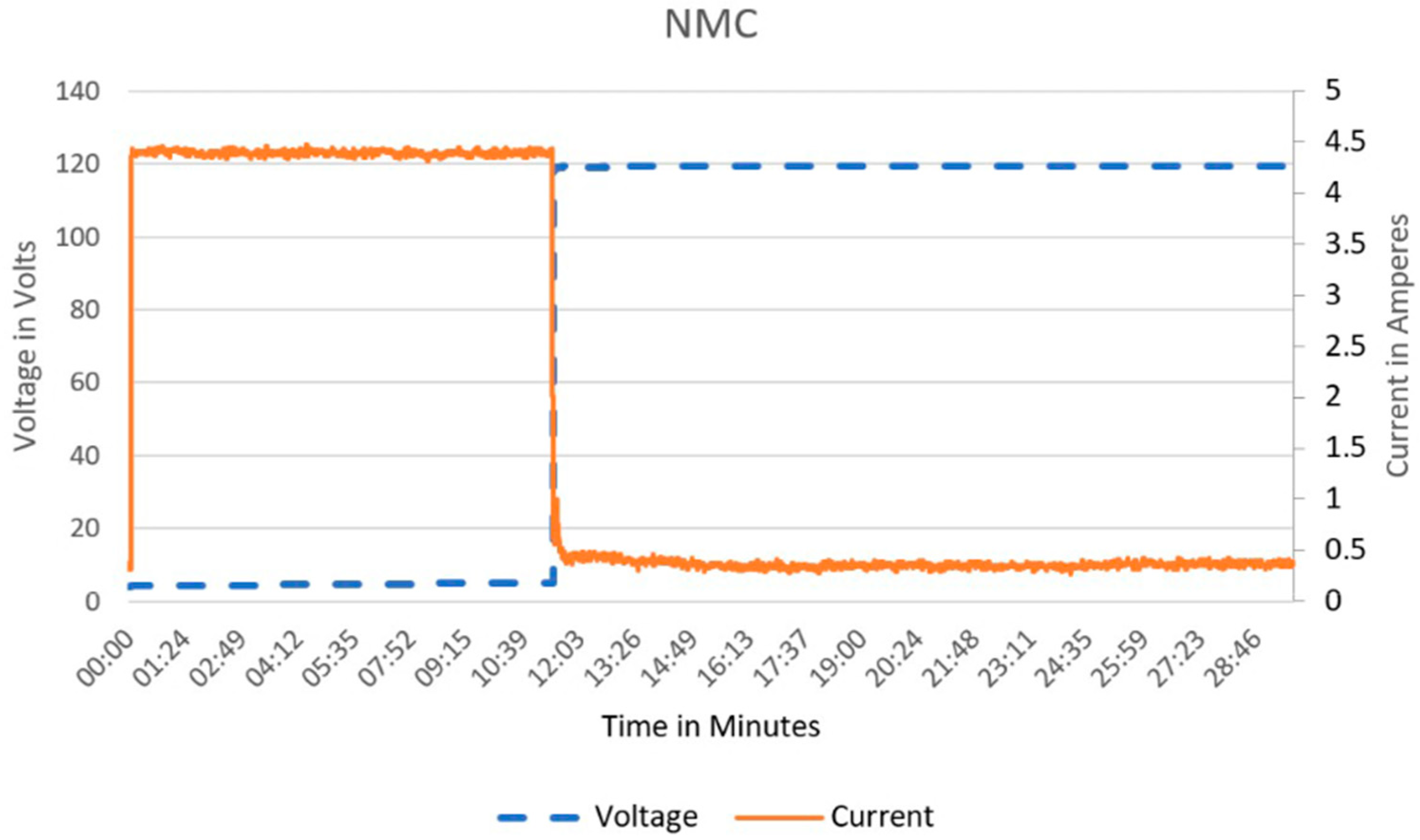
To obtain an overview of the raw data, three categories of hazard level 3–5 [21] were defined for the tested series. The first test result category summarizes the data for the correct CID behavior (hazard level 3) [21]. All tested cells showed the expected triggering behavior (refer to Figure 6), i.e., after an overcharge time of 10 min, the internal gas pressure was sufficient to open the CID, which leads to an out-gassing process of the cell (current drops and voltage increases). The CID had correctly interrupted the current flow and prevented further overcharging of the cell, which is categorized as a safe condition, i.e., marked as hazard level 3 [21] (marked as green safe behavior).
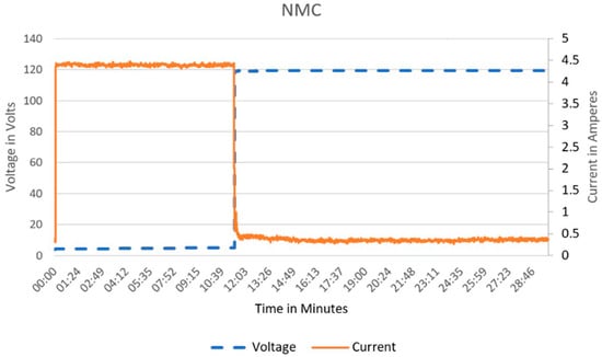
Figure 6.
CID has correctly interrupted the current flow. This is typical behavior for the correct separation of CID. Hazard level 3 [21].
The next category summarizes the behavior that has been observed as the incorrect triggering of the CID (refer to Figure 7). During the experiment, it was found that, in this state, there was strong smoke development with increased temperatures due to partial interruption in current flow by the CID. Therefore, this is classified as a non-safe condition hazard level 4 [21] (marked as yellow, unsafe behavior).
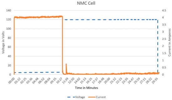
Figure 7.
The CID has partially interrupted the current flow. This is not typical behavior for separating CID. Hazard level 4 [21].
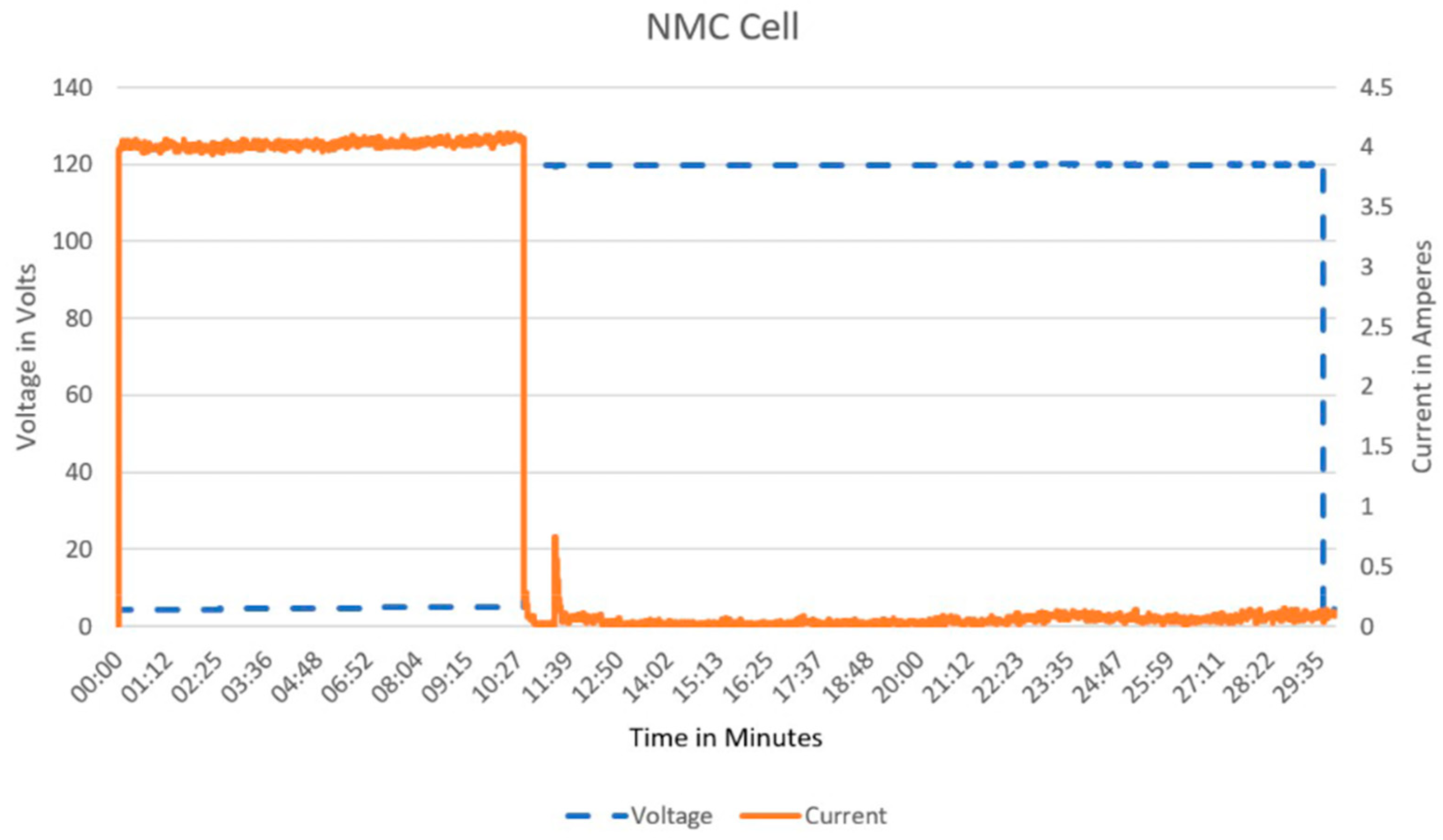
The last category included the CID data with a false triggering behavior of the CID, which could separate current and voltage only briefly or not at all, and therefore did not prevent overcharging of the cell (refer to Figure 8). This eventually leads to the burning or explosion of the cell and is therefore classified as the non-safe condition at hazard level 5 or higher (marked as red, unsafe behavior).
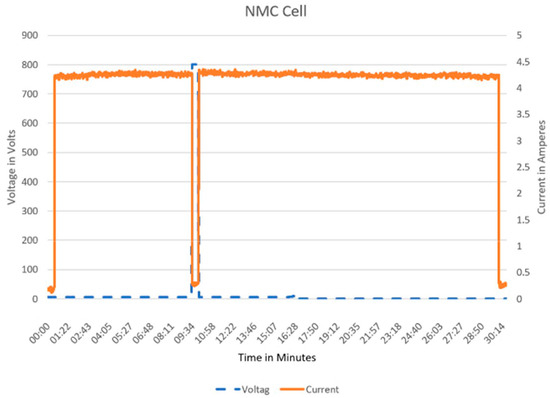
Figure 8.
The CID was not able to disconnect the current flow. The overcharging process leads to burn out or explosion of the cell. Hazard level 5 [21] or higher.
5. Discussion
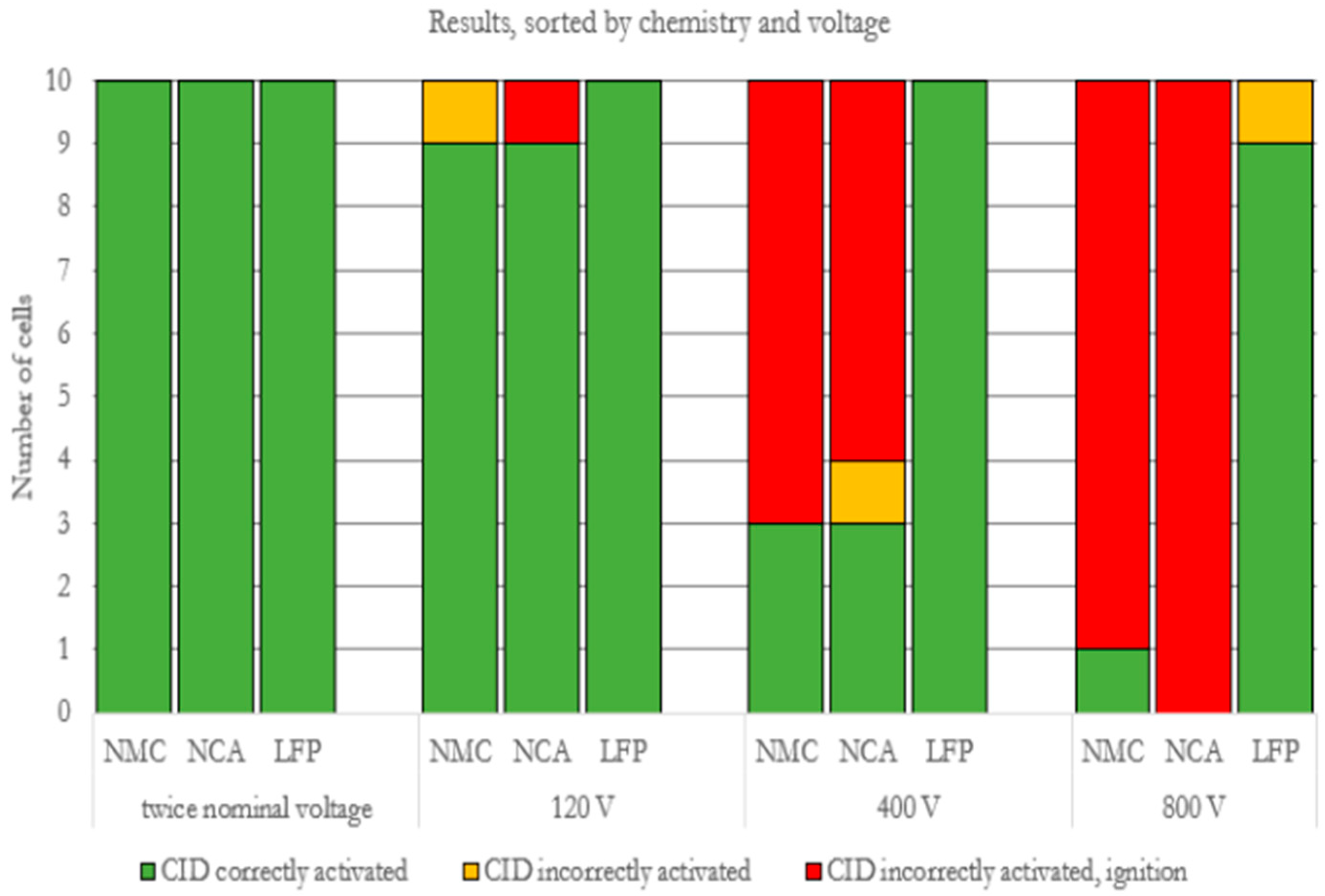
According to the battery test standards by FreedomCAR, it is difficult to push cells to their safety limits, i.e., independent of the type of cell chemistry. If the overcharging is performed at twice the nominal voltage, the cell is not being pushed to the extreme limits, and there will be no dangerous behavior. In such a voltage range (2–5 V), the CID correctly detaches the plus and minus poles without igniting the cell. However, the test standards do not demonstrate the reality of the areas in which lithium cells are used. It must be noted that in the energy storage market, there are increasingly higher interconnected series switching systems with voltages of up to 800 V. Considering the results of the first test series up to 120 V, it can be seen that the first critical cell behavior occurs with NMC and NCA chemistries, while the LFP chemistry is safe in comparison and there are no ignitions or fires of hazard level 5 [21] or higher. During the 400 V test, it is noticed that the critical cases for the NMC and NCA chemistries have doubled compared to the 120 V (see Figure 9), but the LFP cell can still be considered uncritical. For the 800 V tests, NMC and NCA cells performed almost the same, i.e., ignition stage, while the LFP cells had the first case of critical behavior when compared with the 120 V and 400 V test series (see Figure 9).
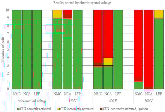
Figure 9.
Results of the abuse tests, sorted by voltage level.
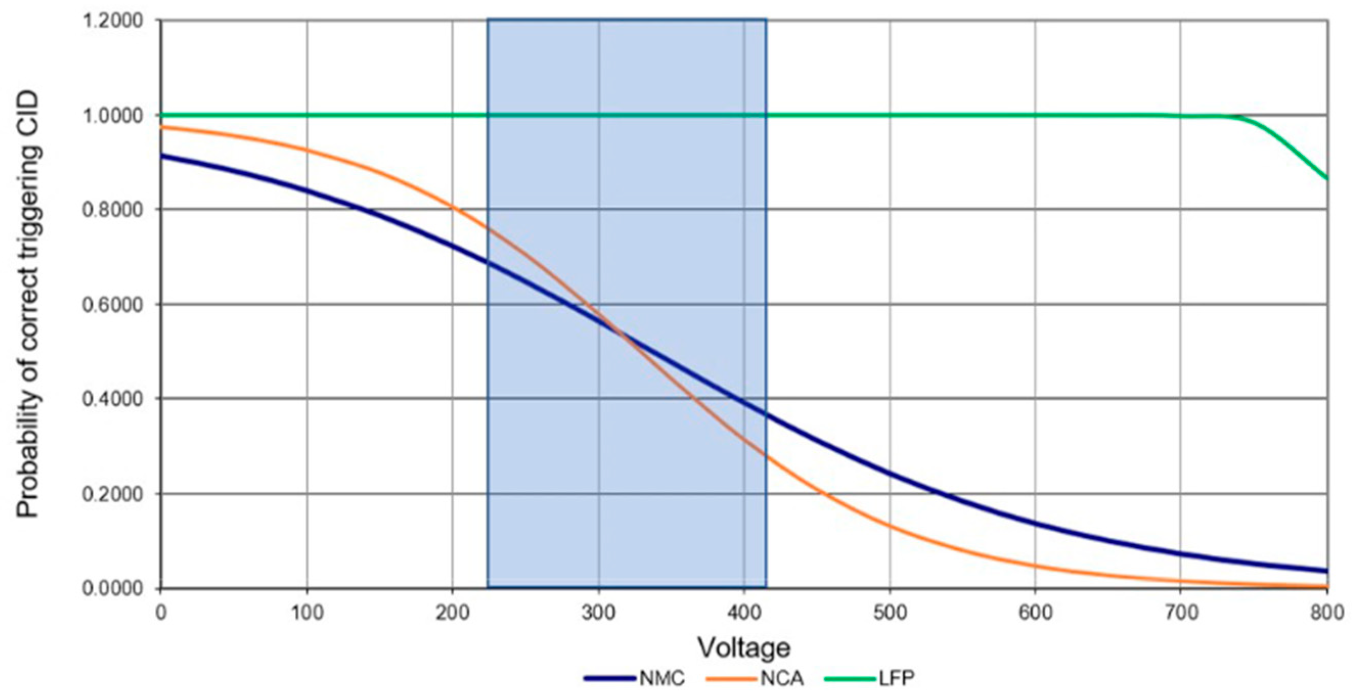
Considering all three voltage levels, it was found that burn-up and/or degassing occurred at each level. However, despite having worse characteristics from an energy storage perspective, LFP cells demonstrated the utmost safety. The test series also showed that for all cells classified as “unsafe”, (see Figure 10) the energy supply to the cell could not be stopped, i.e., the charging current could not be interrupted. The possible explanation could be that an arc is produced during the triggering of CID, which allowed the charging current to continue to flow. During this phase, there could be a small point of contact between the separated anode and cathode, which leads to a high current density. It must also be considered that, for a very short time, the distance between the two contacts created by the triggering of the CID is very small, which also increases the breakdown voltage and could potentially generate an arc.
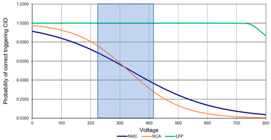
Figure 10.
Illustration of the binary logistic regression, between the state safe 1 and the state unsafe 0. The blue marked area is the voltage range of currently very common electric cars.
6. Conclusions
Considering all the results obtained from all test series, it can be concluded that the current standards for testing the safety of a cell in a battery system are not sufficient. As mentioned in Section 2., in battery systems with a high system voltage of series-connected cylindrical cells, a voltage drop can occur at an open CID, which can lead to the formation of a critical arc (refer to Figure 8). Consequently, the cell burns or can explode. Therefore, the cell tests with twice the nominal voltage are not significant in terms of the safety behavior of a cell if the cell is connected in series in a battery system, and so the current standards must be revised. It is recommended that the tests on the cell level should be performed at least up to the maximum voltage level of the battery system where the cells are planned to be installed and operated.
Additionally, it was found that the hazard potential increases while overcharging the cells with very high voltages. Therefore, the application of cells with CID should be reconsidered in a battery system, where such cells are interconnected in series in large quantities. The reason for such consideration is because a tripping CID might cause a catastrophic failure of the cell. The alternate solution for this problem is to design the cells with CID in a way that the CID can withstand such high voltages.
From a future research point of view, the arc issues can be considered and investigated to understand whether the charging current continues to flow via an arc or through the electrolyte. This investigation will provide better insight into the internal safety mechanisms of the cells and will provide information on what exactly causes the charging current not to be disconnected after the CID has been triggered.
Author Contributions
Conceptualization, J.H., C.S., F.M. and H.-G.S.; methodology, J.H., C.S. and F.M.; software, J.H.; validation, J.H., H.-G.S., Y.K. and P.L.; formal analysis, J.H., C.S. and F.M.; investigation, C.S. and S.S.; resources, H.-G.S.; data curation, J.H.; writing—original draft preparation, J.H., C.S. and F.M.; writing—review and editing, Y.K., J.H., P.L. and H.-G.S.; visualization, J.H. and S.S.; supervision, H.-G.S. and Y.K.; project administration, J.H.; funding acquisition, H.-G.S. All authors have read and agreed to the published version of the manuscript.
Funding
This research was funded by the Technische Hochschule Ingolstadt and the C-ECOS, CARISSMA Institute and partly financed by the research Project SUSTAIN. Funding number: 16BZF320E.
Institutional Review Board Statement
Not applicable.
Informed Consent Statement
Not applicable.
Data Availability Statement
The data presented in this study are available on request from the corresponding author due to legal reasons.
Acknowledgments
We thank Walter Strasser and Nikolas Jaroch from Technische Hochschule Ingolstadt for supporting the test series at Fort Prinz Karl and for their helpful suggestions on the manuscript.
Conflicts of Interest
The authors declare no conflicts of interest.
Correction Statement
This article has been republished with a minor correction to an author’s ORCID. This change does not affect the scientific content of the article.
References
- IEC 61140:2016; Protection Against Electric Shock—Common Aspects for Installation and Equipment. United Nations: New York, NY, USA, 2016. Available online: https://www.vde-verlag.de/iec-normen/222483/iec-61140-2016.html (accessed on 2 September 2024).
- Schröder, R.; Aydemir, M.; Seliger, G. Comparatively assessing different shapes of lithium-ion battery cells. Procedia Manuf. 2017, 8, 104–111. [Google Scholar] [CrossRef]
- Bosch eBike-Akkus. Available online: https://www.bosch-ebike.com/de/produkte/akkus (accessed on 2 September 2024).
- Jossen, A.; Weydanz, W. Moderne Akkumulatoren Richtig Einsetzen; Matrixmedia: Göttingen, Germany, 2022. [Google Scholar]
- Davide, A. Battery Management Systems for Large Lithium-Ion Battery Packs; Artech: London, UK, 2010. [Google Scholar]
- Xu, B.; Kong, L.; Wen, G.; Pecht, M.G. Protection Devices in Commercial 18650 Lithium-Ion Batteries. IEEE Access 2021, 9, 66687–66695. [Google Scholar] [CrossRef]
- Augeard, A.; Singo, T.; Desprez, P.; Abbaoui, M. Contribution to the Study of Electric Arcs in Lithium-Ion Batteries. IEEE Trans. Compon. Packag. Manuf. Technol. 2016, 6, 1066–1076. [Google Scholar] [CrossRef]
- Doughty, D.H.; Crafts, C.C. FreedomCAR: Electrical Energy Storage System Abuse Test Manual for Electric and Hybrid Electric Vehicle Applications; Sandia National Laboratories (SNL): Albuquerque, NM, USA; Livermore, CA, USA, 2006. [Google Scholar]
- Garche, J.; Brandt, K. Electrochemical Power Sources: Fundamentals, Systems, and Applications Chapter 7—Lithium-Secondary Cell: Sources of Risks and Their Effects; Elsevier: Amsterdam, The Netherlands, 2018. [Google Scholar]
- Ohsaki, T.; Kishi, T.; Kuboki, T.; Takami, N.; Shimura, N.; Sato, Y.; Sekino, M.; Satoh, A. Overcharge reaction of lithium-ion batteries. J. Power Sources 2005, 146, 97–100. [Google Scholar] [CrossRef]
- Fernandes, Y.; Bry, A.; de Persis, S. Identification and quantification of gases emitted during abuse tests by overcharge of a commercial Li-ion battery. J. Power Sources 2018, 389, 106–119. [Google Scholar] [CrossRef]
- Golubkov, A.W.; Scheikl, S.; Planteu, R.; Gernot, V.; Wiltsche, H.; Stangl, C.; Fauler, G.; Thaler, A.; Hacker, V. Thermal runaway of commercial 18650 Li-ion batteries with LFP and NCA cathodes—Impact of state of charge and overcharge. RSC Adv. 2015, 5, 57171–57186. [Google Scholar] [CrossRef]
- Theil, S.; Fleischhammer, M.; Axmann, P.; Wohlfahrt-Mehrens, M. Experimental investigations on the electrochemical and thermal behaviour of LiCoPO4-based cathode. J. Power Sources 2013, 222, 72–78. [Google Scholar] [CrossRef]
- Müller, P. Detektion von Stromschwachen Störlichtbögen in Niederspannungsschaltanlagen; Copyright Peter Müller: Stuttgart, Germany, 2014. [Google Scholar]
- Schweiger, H.-G. FISITA Intelligent Safety, 2023. FISITA, 2023. Available online: https://go.fisita.com/store/bookstore/fisita-intelligent-safety-2020-white-paper (accessed on 11 September 2023).
- UN ECE R100; Uniform Provisions Concerning the Approval of Vehicles with Regard to Specific Requirements for the Electric Power Train. United Nations: New York, NY, USA, 2022. Available online: https://unece.org/transport/documents/2022/03/standards/regulation-no-100-rev3 (accessed on 2 September 2024).
- ISO 12405-4:2018; Electrically Propelled Road Vehicles—Test Specification for Lithium-Ion Traction Battery Packs and Systems. International Organization for Standardization: Geneva, Switzerland, 2018. Available online: https://www.iso.org/standard/71407.html (accessed on 2 September 2024).
- UN 38.3; Transport of Dangerous Goods. United Nations: San Francisco, CA, USA, 2015.
- ISO 6469-1:2019; Electrically Propelled Road Vehicles. Safety Specifications. Vehicle Operational Safety. ISO: Geneva, Switzerland, 2019. Available online: https://www.dinmedia.de/de/norm/iso-6469-1/307406208 (accessed on 2 September 2024).
- Sauer, D.U.; Kowal, J.; Willenberg, L.; Rahe, C.; Teuber, M.; Drillkens, J.; Ringbeck, F.; Schäper, C. Elektrifizierung des Antriebsstrangs: Grundlagen—Vom Mikro-Hybrid zum Vollelektrischen Antrieb; Springer: Berlin/Heidelberg, Germany, 2019; pp. 61–98. [Google Scholar]
- EUCAR. Hazard Level. Battery Requirements for Future Automotive Applications EG BEV&FCEV. Available online: https://eucar.be/wp-content/uploads/2019/08/20190710-EG-BEV-FCEV-Battery-requirements-FINAL.pdf (accessed on 2 September 2024).

Disclaimer/Publisher’s Note: The statements, opinions and data contained in all publications are solely those of the individual author(s) and contributor(s) and not of MDPI and/or the editor(s). MDPI and/or the editor(s) disclaim responsibility for any injury to people or property resulting from any ideas, methods, instructions or products referred to in the content. |
© 2024 by the authors. Licensee MDPI, Basel, Switzerland. This article is an open access article distributed under the terms and conditions of the Creative Commons Attribution (CC BY) license (https://creativecommons.org/licenses/by/4.0/).