Featured Application
Applications for this work include rapid prototyping of fan or compressor casings using additive manufacturing.
Abstract
Additive manufacturing (AM) presents significant cost savings and lead time reductions because of features inherent to the manufacturing process. The technology lends itself to rapid prototyping due to the streamlined workflow of quickly implementing design changes. Compared to traditional machining, AM techniques are simpler in execution for design engineers because they do not require detailed engineering drawings and they typically make use of the nominal geometry in computer models. A novel transonic fan casing assembly has been developed that makes use of AM inserts surrounding the rotor to provide an opportunity to cost-effectively change the corresponding flowpath. The rapid prototyping design philosophy developed from this work will allow for numerous experimental studies into the effects that different design parameters of casing geometries have on fan aerodynamic performance. A fan stage representative of a small turbofan engine was successfully tested with smooth-walled, additively manufactured inserts as a baseline case for future configurations. Before installing the 3D printed casing assembly, computational thermal stress analysis was performed to reduce the risk in implementation due to the demanding environment associated with the rotor. AM components and materials typically have nonlinear mechanical properties, adding to the complexity of the structural analysis. As part of the research, steady aerodynamic performance was measured over the entire relevant operating range of the fan.
1. Introduction
Developing a new aircraft engine is expensive and poses a significant risk, especially when cutting-edge fan or compressor hardware is incorporated. To mitigate the associated risk, engine companies will employ component-level testing on dedicated rigs representing relevant fan and compressor stages. The rigs provide valuable component-level experimental performance data across the entire operating range of a given machine. Furthermore, computational tools cannot accurately predict the precise onset of flow instabilities, which also necessitates experimental verification. Despite the expected payoff, the cost associated with turbomachinery test rigs is high and development time may take years. Components are typically precision machined and there is no benefit of production at scale as most rig components are one-off pieces. To reduce the development time and associated cost of rig testing, additive manufacturing (AM) and a rapid prototyping mindset show promise.
Additive manufacturing is a powerful tool for component design as it allows for efficient and cost-effective prototypes. AM components have had some commercial success in the aviation and power generation industries. A reduced-weight fuel nozzle manufactured using 3D printing was successfully designed and implemented by GE in the CFM LEAP engine [1]. Additionally, Siemens completed testing on an AM turbine blade at full engine conditions [2]. AM presents an opportunity to replace the traditional mindset of manufacturing at scale with more flexible “Engineered-To-Order” components for specific design requirements as coined by Novotny et al. [3].
AM is advantageous for components with high complexity, therefore it has seen increased use in turbomachinery research, where components are often complicated and require one-off pieces [3,4]. The entire stationary diffusion system for an aero-engine centrifugal compressor was 3D printed using stereolithography (SLA) and successfully tested over the full operating range [5]. AM was also used successfully by the Naval Postgraduate School to implement a casing treatment on a transonic rotor [6,7]. The individual passages of the treatment were 3D printed and then cast. It would be most cost-effective and take most advantage of the AM process to have 3D printed inserts that could simply be exchanged and installed after printing without any required machining or finishing operations. There is currently no such application until now. A novel fan casing assembly, known as the adaptable fan casing, was designed to make this workflow a reality.
2. Materials and Methods
2.1. Research Facility and Test Article
The adaptable fan casing was tested at the Purdue University Fan Research Facility. A detailed description of the space and capabilities of the facility can be found in Cusator et al. [8]. The test cell features an 18 in (0.46 m) transonic fan stage representative of a small turbofan engine. The rig was donated by Honeywell Aerospace and contains independent bypass and core throttles downstream to control the bypass ratio (BPR). The facility contains the equipment required for flow straightening upstream of the test article and the instrumentation required to provide detailed flow measurements.
The 18 in transonic fan has a design speed of around 19,000 rpm and flows approximately 60 lbm/s (27 kg/s) of air at this speed. The rotor consists of 22 individual slotted disk blades and 53 stator vanes downstream. The maximum tip speed is 1500 ft/s (457 m/s), which produces a relative Mach number at the tip of 1.5. At design speed, a significant portion of the rotor span operates with transonic relative flows. Fan details are provided in Table 1.

Table 1.
Relevant fan parameters.
Baseline aerodynamic performance was characterized by throttling the fan to stall at various corrected speeds (Nc) with corresponding BPRs from 70% Nc to 100% Nc with an aluminum fan casing installed. The maximum total pressure ratio was around 1.8 at design speed and the maximum total temperature ratio was less than 1.25. The aluminum fan casing is referred to as the baseline case and consists of a single piece of precision machined 6061 aluminum with an abradable layer surrounding the rotor section. The casing mounts to the rest of the hardware through a bolted connection. Due to the casing contouring, cold tip clearance can be adjusted by placing shims aft of the casing flange. Throughout the flowpath, there are static pressure taps to measure pressure rise, light probes for blade vibration monitoring, capacitance probes for tip clearance measurement, and a thermocouple to monitor fan casing temperatures. A cutaway of the fan rig with the aluminum casing installed is shown in Figure 1.
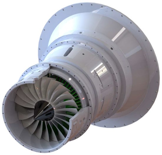
Figure 1.
Fan rig render with rotor cutaway.
The new fan casing assembly described in this paper interfaces with the rest of the hardware through the same bolted connection to provide a simple installation. The individual pieces are assembled before they are mounted onto the rig.
2.2. Adaptable Fan Casing Design
The new fan casing is referred to as the adaptable fan casing due to its design intent of incorporating swappable inserts as the flowpath surrounding the rotor. The overall architecture of the assembly is made up of three permanent metal components constructed of 6061 aluminum, and six interchangeable 3D printed inserts made from a high-temperature ceramic-like thermoset plastic called PerFORM. The major components are shown installed around the fan in the render in Figure 2. The metal components required precision machining to ensure the concentricity of the final build and to aid in assembly. Additionally, alignment pins were incorporated on both sides to align the AM inserts. The inserts have notches on both the forward and aft sides to accommodate the pins. Aluminum was chosen as the metal build material due to its corrosion resistance, machinability, mechanical properties, and low density compared to stainless steel. The lower density minimized the overhung mass over the rotor and made installation smoother.
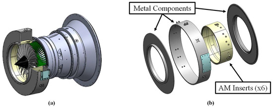
Figure 2.
AM fan casing installed over the rotor (a) along with an exploded view (b) for reference.
The AM inserts are built through a manufacturing process called SLA. SLA is a vat polymerization process during which a liquid resin is cured in layers using an ultraviolet light [9]. As the layers cure, complex components can be constructed. The layer thickness produced by the light governs the geometric capabilities such as feature size and surface finish. It also dictates component size, printing time, and mechanical strength. This plastic presented significant risk and design challenges in its incorporation over the rotor. The ultimate tensile strength of the PerFORM is significantly lower compared to other aerospace metals. Furthermore, the tolerances on the prints are slightly higher. A typical fan casing may have a profile tolerance of around 0.010″ (0.25 mm), while the tolerance on the inner radius of the AM inserts is roughly 0.020″ (0.5 mm). However, the expected payoff due to associated cost, lead time, and available component complexity was worth the endeavor.
Table 2 shows representative values of lead time, cost, and feasible part complexity for AM plastic, AM metal, and traditionally machined components. Both AM plastic and AM metal present significant cost and lead time reductions compared to machining. Furthermore, 3D printed parts do not require drawings with individual features called out, which further reduces the development time. Printing in plastic offers the most outstanding advantage as it has a lead time on the order of weeks and undercuts the cost of AM metal components by a factor of two. In the span of one month, it is conceivable to print, implement, and test a new flowpath design if AM plastic inserts are used. The monetary values listed in Table 2 take into account the associated material cost.

Table 2.
Cost, lead time, and complexity comparison for three manufacturing techniques.
Further considerations in the cost-benefit analysis included long-term maintenance costs and replacement cycles. The fatigue life of the PerFORM was evaluated experimentally and found to be adequate [10]. The number of blade pass events that occur during data collection for a fan map is on the order of 100 million. Fatigue life assessments for thermoset plastics like the PerFORM are difficult because they are typically based on linear elastic materials. To effectively collect aerodynamic data, inserts should be expected to last through roughly 60 h worth of data collection and numerous stall cycles. The fan was stalled multiple times at different corrected speeds and approximately 45 h were accumulated on the inserts used for this project. There were no signs of fracture in the inserts upon inspection and they can likely endure further testing. Any advantage of an aluminum fan casing in terms of fatigue life would be irrelevant in this case because the required hours before failure of the AM inserts would likely be higher than the required testing hours.
The most significant impact on the longevity of the inserts would be the fan blade rubbing against the surface. If the blade were to rub the surface of the inserts, all six would need to be replaced with new prints. Aluminum fan casings typically have an abradable layer to protect the blade tips. If a rub occurred, this abradable layer would need to be reapplied, which is nontrivial and costly. Furthermore, depending on the required flowpath geometry, it may be impractical to implement this abradable layer. Thus, an aluminum insert would likely need to be replaced if a rub occurred as well and offers no additional benefit in the event of a rub compared to the PerFORM.
Leaks are prevented between components using O-rings and room temperature vulcanizing (RTV) silicon. The AM inserts were designed with a jagged interface where they meet in the assembly to discourage air leaks from the flowpath. The outer diameter where the inserts meet is sealed with a layer of RTV silicon. Furthermore, O-rings span the axial length of each insert in the middle of the jagged interface. Splitting the annulus presents a unique advantage of the assembly. Individual inserts can be exchanged depending on requirements for instrumentation or part-circumference flowpath changes.
A major advantage of AM techniques lies in the instrumentation capabilities. Fan casings typically have extensive instrumentation required for measuring various quantities through the rotor. Some of the measurements involve light probes for tip deflections, capacitance probes for tip clearance, and static pressure taps to measure the pressure rise. Each piece requires specific features and they can quickly take up valuable space in machined hardware. Traditionally machined parts would require individual callouts on detailed engineering drawings for the different features, which can add significant costs and time to the development process as well as the overall machining process. Furthermore, more complicated features can be implemented in AM components that would have otherwise been impossible to machine. Meier and Clement made extensive use of SLA printing to include static pressure taps in previously unavailable locations in a centrifugal compressor diffusion section [5,11]. Additionally, designers for AM components do not need to take into account traditional tooling requirements that might interfere with the resolution or spacing. Static pressure taps and light probes often have optimal circumferential placements around the annulus. With traditional machining, the final layout may not be optimal after taking into account the manufacturing and tooling processes. The workflow is summarized in Figure 3. The flowpath instrumentation is simpler in the fan compared to the centrifugal compressor. Figure 4 shows the layout of the static pressure taps surrounding the fan rotor. The axial resolution of the taps was increased compared to the aluminum configuration. Additionally, time was saved by using the CAD models for the printing process compared to engineering drawings.

Figure 3.
Workflow diagram from a new flowpath design for implementing and testing the aerodynamic performance effects.
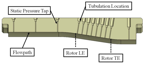
Figure 4.
AM insert cross-section pointing out key features associated with the static pressure taps.
2.3. SLA Material Properties
A major design challenge associated with the PerFORM lies in the mechanical properties and the thermal expansion coefficient. Due to the nature of the cross-linked polymers in the SLA building process, AM materials using this process of construction exhibit a glass transition temperature. They do not have a melting point in the traditional sense and will transform into a rubbery state above the glass transition temperature [10]. Independent material testing on the PerFORM was completed to provide insight and judge feasibility in the demanding application of a diffuser for an aero-engine centrifugal compressor. Details on the tests and material properties can be found in Adkins–Rieck’s thesis on the subject [10]. Stress–strain curves are reproduced in Figure 5 using the acquired tensile test data. SLA materials have anisotropic properties due to the influences of the build direction. Multiple sets of tensile tests representing the different build directions and temperatures were performed and recorded. The curves in Figure 5 represent the weakest of the three build directions to account for this in the mechanical analysis.
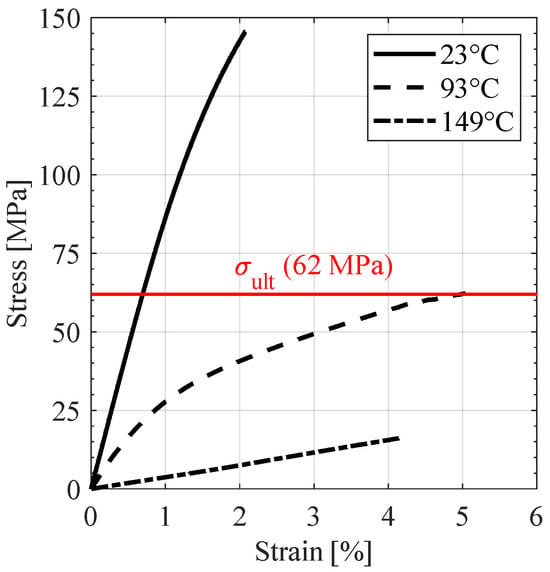
Figure 5.
PerFORM stress–strain curves at multiple temperatures.
Mechanical behavior changes significantly between 73 °F (23 °C, room temperature) and 200 °F (93 °C). At room temperature, the ultimate tensile strength is around 21 ksi (145 MPa) and reaches an ultimate strain of 2% at failure. The curve is mostly linear, indicating there is little or no plastic deformation before the ultimate strength is exceeded. At 200 °F, the ultimate strength is around 9 ksi (62 MPa), or about half of the room temperature mechanical strength. Additionally, the material sample reached an ultimate strain of 5% before failure. The curve at 200 °F exhibits more plastic deformation compared to the room temperature curve. The highest-temperature curve shown, 300 °F (149 °C), presents the most significant reduction in strength, producing an ultimate strength of around 2.5 ksi (17 MPa). The glass transition temperature for PerFORM is close to 200 °F, which helps to explain some of the behavior. At temperatures close to this value, the stiffness is reduced, but as the temperature exceeds it by a significant margin, the material becomes much weaker and more brittle [10]. Fortunately, temperatures in the fan flowpath are rarely expected to exceed 200 °F, which makes this an excellent application for this material. The data obtained at this temperature were imposed as the structural limit for the purposes of the analysis.
The linear thermal expansion coefficient for the PerFORM presents a second significant design challenge. Compared to the surrounding aluminum components, the PerFORM has a much higher thermal expansion coefficient, and the difference increases to a greater degree at elevated temperatures. Figure 6 shows the coefficients for the PerFORM and 6061 aluminum. Values for the PerFORM were determined from the material testing and values for the aluminum were obtained from the ANSYS 2022/R1 material database. At room temperature, the PerFORM will expand about twice as much as the aluminum, and at 200 °F, the thermal expansion will be greater by a factor of five.
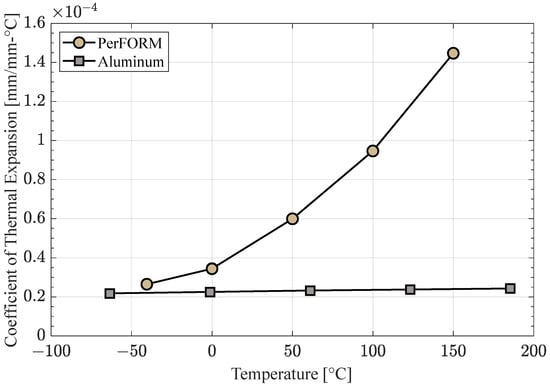
Figure 6.
Thermal expansion coefficients for 6061 Aluminum and PerFORM.
Due to the mismatch of thermal expansion coefficients, thermal stresses will build up as both components heat up during fan operation. Herein lies the critical aspect of the mechanical analysis. The PerFORM must withstand the expected thermal stress due to the constraining aluminum parts. However, at elevated temperatures where the stress is highest, the mechanical strength decreases, creating a conflicting design goal. In reality, small gaps will be present between the inserts and the aluminum to account for manufacturing tolerances. The gaps are kept to a minimum (on the order of 0.005″) to ensure the concentricity of the assembly. A secondary benefit of aluminum is its higher thermal expansion coefficient compared to stainless steel. The aluminum will grow and alleviate some of the stress. For the mechanical analysis, the gaps between components were removed to represent the stiffest, worst-case scenario under the expected operating conditions.
Despite the competing material properties, the PerFORM is still the most desirable option compared to other common SLA resins for this application. Clement et al. conducted a detailed review of different SLA resins and concluded that PerFORM remains a top choice [5]. It offers a high heat deflection temperature along with adequate mechanical strength at elevated temperatures. Additionally, the available mechanical properties obtained from material testing and the established lab best practices gave it an advantage over new or unfamiliar resins.
2.4. Thermal and Structural Analysis
To determine application feasibility, thermal and structural analyses were conducted in 1D, 2D, and 3D. The idea was to use the 1D analysis to obtain a reasonable confidence level in the overall application of the PerFORM, the 2D analysis to iterate on major design features, and the 3D analysis to mitigate risk and obtain detailed stress distributions that would take into account all major aspects of the assembly.
Failure criteria were also a unique challenge associated with this assembly. Materials typically experience ductile or brittle fracture when loaded past the ultimate strength. One arbitrary distinction based on elongation at failure states that ductile failure constitutes a strain of at least 0.05 before a fracture occurs [12,13]. By examining stress–strain curves, ductile materials might level off more due to yielding while brittle curves will end more abruptly and appear more linear. Ductile materials are typically associated with metals while common brittle materials consist of ceramics. PerFORM is described as a ceramic-like thermoset plastic and tends to flake or crack from machining operations, indicating that its nature is likely brittle. However, the stress–strain curve at 200 °F reaches an ultimate strain of 5% and appears to show some evidence of yielding before fracture. To further complicate the situation, the curves at room temperature and 300 °F exhibit brittle behavior. It appears that failure near the glass transition temperature would be more ductile in nature compared to other temperatures. To instill confidence and mitigate risk, failure criteria for both ductile and brittle materials were used and the stresses had to be manageable for both analysis methods. Furthermore, the ultimate strength was derived using a tensile test, but significant compressive stresses were expected to be present. Since the ultimate compressive strength (assuming no structural instabilities) is typically higher or similar to the ultimate tensile strength, the latter value was used for the analysis [13,14]. This is especially true for brittle materials as they are typically significantly stronger under compressive loads.
Specific failure criteria included the distortion energy theory (von Mises stress) and maximum normal stress theories. The distortion energy theory compares the von Mises equivalent stress to the yield strength (in this case the ultimate tensile strength) to determine a safety factor and is well-regarded for ductile materials. To provide insight into brittle failure, the maximum and minimum normal stresses were compared to the ultimate strength to determine a safety factor. In theory, brittle failure will occur when the maximum normal stress (tension) or the magnitude of the minimum normal stress (compression) exceeds the ultimate strength. As a conservative estimate, the ultimate strength used in the analysis was 8900 psi, which is representative of the failure point from the weakest build direction at 200 °F.
The simplest form of structural analysis can be conducted in 1D and assumes the PerFORM inserts are a cohesive cylinder of uniform temperature. These assumptions are not unreasonable in the area at the aft end. In this location, the inserts are constrained by the aluminum and will heat up the most from the total temperature rise generated by the fan. Equation (1) represents the thermal stress, , that will accumulate in the inserts due to thermal expansion with no additional gaps between the materials. This assumes the PerFORM will constantly contact the aluminum in this area and the aluminum is rigid. is the modulus of elasticity, is the coefficient of thermal expansion, and is the difference in temperature between the inserts and the zero-strain reference temperature for the PerFORM (70 °F, 21 °C). The elastic modulus and thermal expansion coefficient both depend on the body temperature, therefore linear interpolation of the experimental data was used to determine these properties at different temperatures.
Figure 7 shows the expected 1D thermal stress with respect to the body temperature of the AM inserts. Stress increases with the applied thermal load and reaches a maximum of 2800 psi around 220 °F. Above this temperature, the stress decreases slightly due to the proximity to the glass transition temperature and the resulting reduction in stiffness. This is accounted for in the temperature dependence of the elastic modulus. Due to the limited nature of 1D analysis, the direction of stress must be assumed. Thermal stress in a component with external constraints, such as the outer surface of the AM inserts, will be subjected to compressive stresses, while components under internal constraints, such as the inner diameter, will incur tensile stresses [12]. Since it is unclear which will dominate, the 1D results incorporated both stress states. If the inserts incur large tensile stresses, there is additional failure risk due to a stress concentration in the alignment pin notch. An appropriate stress concentration factor was calculated as 1.86 and applied to the maximum thermal stress value determined previously. Hence, the maximum anticipated tensile stress would be 5200 psi. The stress concentration factor was calculated using the formulas in Young and Budynas’ textbook and the nominal CAD geometry [12]. Both maximum anticipated stress values are well below the ultimate strength and indicate that the design is likely feasible without any need for additional gaps between components.
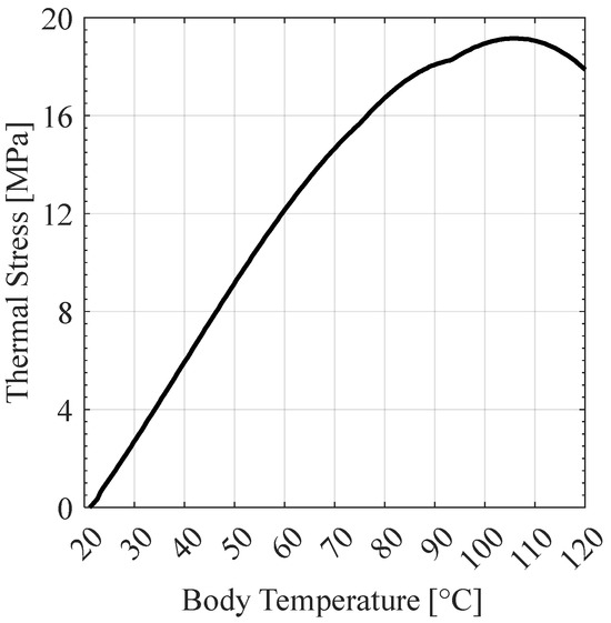
Figure 7.
Predicted 1D thermal stress.
The limitations in the 1D analysis necessitate the use of commercial computational tools for higher-order analysis. ANSYS Mechanical 2022/R1 was used to develop computational models for the assembly in 2D and 3D. The 2D analysis was performed using an axisymmetric analysis of the adaptable fan casing cross-section. In the software, the axisymmetric analysis assumes a constant cross-section revolving around the center. This means that a more accurate solution for the entire insert can be developed compared to the 1D method. The 2D analysis lacks some key details that are resolved using the 3D analysis; however, it performs much better for design iteration when taking into account computational cost. The axisymmetric model can reach a solution in roughly 15 to 30 min depending on mesh size, while the 3D analysis requires hours. The goal was to use the 2D analysis results to gain insight into the predicted stress state and incorporate any design changes that would be required.
Both analyses followed the same workflow to obtain results. First, the components were meshed using the ANSYS dedicated meshing tool. Expected temperature loads due to the fan flowfield were then applied and a steady-state thermal analysis was run to determine the temperature distribution in the inserts and metal components. The temperature distribution was then applied to the structural model along with other representative boundary conditions to obtain stresses that arise from the thermal loading.
The cross-section used in the 2D analysis is shown in Figure 8. Thermal analysis boundary conditions consisted of an applied temperature distribution on the flowpath surfaces. Upstream of the fan leading edge region, the temperature was set to ambient conditions. Downstream of the trailing edge region, the temperature was set to approximately 200 °F, which represents the hottest allowable rotor exit temperature due to the material constraints. The ratio of these temperatures was roughly the value of the highest total temperature ratio that the fan achieves. Between these two regions, a linear temperature distribution was imposed to represent the effect of the total temperature rise through the rotor. It is possible to obtain shroud temperatures using computational fluid dynamics (CFD); however, the specific values can be inaccurate due to artificial viscosity and other computational effects such as adiabatic walls. Furthermore, an accurate temperature distribution is not critical to the analysis in this area because the plastic is free to expand. Thermal analysis boundary conditions are summarized in Figure 9.
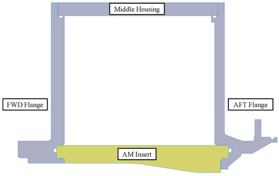
Figure 8.
Two-dimensional CAD model for the AM fan casing assembly.

Figure 9.
Thermal boundary conditions for the AM inserts.
The boundary conditions for the structural analysis consisted of contact interfaces between various components and a fixed surface where the assembly bolts onto the rest of the hardware. In addition, the resulting steady-state temperature distribution was applied. Contact interfaces require definition where different components come together in the model. They can heavily influence the solution and must be chosen as realistic analogs of the physical problem. Frictional contacts were chosen for AM-insert-to-AM-insert interfaces and for AM-insert-to-metal-component interfaces. This type of contact allows for relative sliding between parts and is most representative of the actual physics. A friction coefficient of 0.2 was used on each frictional interface. The backside of the aft metal component contains a fixed surface to constrain the entire assembly and prevent rigid body motion. In the 3D model, this constraint was replaced with cylindrical supports where the bolt holes are integrated into the flange. The contact interfaces where the metal components meet were set as bonded contacts, which is the most rigid connection available. The bonded contacts reduced model complexity compared to modeling the bolts and were not expected to influence the estimation of thermal stresses in critical areas. Pressure loads from the fan were omitted to reduce complexity. Stresses resulting from the pressure rise through the fan were calculated to be an order of magnitude less than the anticipated thermal stress. Thus, they would not significantly influence the model. Important parameters that aided in an accurate solution are summarized in Table 3.

Table 3.
Relevant ANSYS parameter details.
3. Results
The results obtained from the stress analysis, along with the experimental data obtained after installing the physical assembly onto the fan, are described in this section.
3.1. Stress Analysis Results
The thermal results from the 2D axisymmetric analysis and the 3D analysis were similar. Figure 10 shows the steady-state temperature distribution from the 2D analysis. The highest temperatures occur behind the lead edge region of the blade at the aft end. This was anticipated and further validates the assumptions in the 1D results. The temperature distribution also confirms that the area of concern is concentrated at the aft end where the insert is constrained by the aluminum components. This region presents the highest temperatures and least room for thermal growth, which is where thermal stress will increase the most.
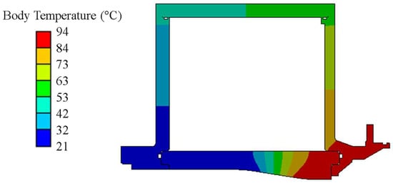
Figure 10.
Two-dimensional steady-state thermal analysis results.
The results from the 2D axisymmetric stress analysis did not indicate any issues with the design. The von Mises equivalent stress and maximum principal stress were well below the ultimate strength for the AM inserts. The minimum principal stress had the highest magnitude of compressive stresses; however, they were still below the ultimate strength. In fact, the compressive stresses at the aft end of the insert, where it is constrained by the aluminum, were of very similar magnitudes compared to those of the 1D analysis. The 2D axisymmetric results do not give any insight into the stresses inside the notches since there is no way to include them in an axisymmetric model. Mesh convergence studies were performed using the 2D analysis and an appropriate amount of elements were incorporated into the model.
The 3D stress results were evaluated at two cross-section planes and focused on the AM inserts; stresses in the metal components were not a concern. The cross-section locations are indicated in Figure 11. Plane A is a slice of the bottom insert that includes the alignment notches. It was important to capture the behavior in this region due to the anticipated stress concentration. Plane B serves as a comparison of the insert without the notch involved. Both planes do not have any geometric features related to instrumentation and so they represent stresses associated with the majority of the inserts. Stresses around major features were checked separately to ensure they were within limits.
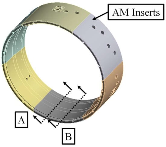
Figure 11.
ANSYS model of the AM insert geometry with results planes called out. Plane A includes the alignment notch and Plane B is free from geometric features.
The values of maximum principal stress were the lowest of the three criteria used in the analysis. This was unsurprising as the highest stresses were expected to be compressive and the magnitudes were similar in both planes. The von Mises equivalent stress was significantly higher in Plane A compared to Plane B. The highest stress occurs at the aft end of the insert at the apex of the notch. Stress contours for the von Mises stress are produced in Figure 12. The von Mises stress is reduced sharply in Plane B, away from the notch. Although the maximum stress is high in this region, it is still below the ultimate strength of the material. In Plane B, von Mises stress is significantly lower. The highest stresses are limited to the aft end of the insert, especially on the outer surface where it contacts the metal. The stress in this area is very similar to the predicted von Mises stress in the 2D axisymmetric model.

Figure 12.
Von Mises stress contours obtained from the 3D analysis in Plane A.
The minimum principal stress calculation produced the highest stresses of all three criteria. Most of the values are less than zero, which represents compressive stresses. The highest magnitudes were localized to the apex of the notch in Plane A. These stresses were more of a concern because the magnitude was nearly equal to the PerFORM ultimate strength. Notably, the stress magnitude decreased sharply at even small distances away from the area. This is likely a result of a stress singularity due to a sharp corner in the geometry. Stresses in Plane B were not of concern. The magnitude was slightly higher at the outer diameter of the aft end compared to the 1D model and the 2D axisymmetric model. The results for Plane A are shown in Figure 13.

Figure 13.
Minimum principal stress contours obtained from the 3D analysis in Plane A.
The most attention was given to the aft notch apex with very high predicted compressive stress. One option that was briefly considered was to increase the radius of the notch in this area. This was not possible as the notch is required to maintain the concentricity of the inserts surrounding the rotor. To achieve this, the alignment pin must fit tightly in the feature. As powerful and convenient FEA tools are, a critical aspect of the analysis lies in the ability to discern physical vs. nonphysical predicted stresses. Stress singularities can arise in FEA models due to geometric discontinuities. Increasing the element count will not necessarily fix the issue either as stress singularities will grow with more elements incorporated in the area. The mesh was refined locally near the notch, and increased stresses were incurred as a result. A closer examination of the 3D results was made to determine whether these high stresses were likely to be physical. Figure 14 shows the 3D ANSYS model of one of the AM inserts. Upon closer inspection of the results superimposed on the mesh, it becomes clear that the high stress is localized to a very small section (dark blue). Moving just one element over from the dark blue region reduces the stress by around 2000 psi (14 MPa). This instilled more confidence that the stress was artificially high due to the geometry. For a valid comparison of stresses predicted using all three failure criteria, a value of 7530 psi (52 MPa) was used for the magnitude of the minimum principal stress. This is the maximum stress value from one element away from the singularity.
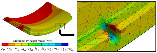
Figure 14.
Three-dimensional view of the minimum principal stress in one of the AM inserts.
Stress analysis typically involves the use of a safety factor, which reflects the margin of error compared to the ultimate strength. The safety factor, S, is defined in Equation (2). For each criterion, represents the maximum magnitude of stress. The ultimate strength is 8900 psi, .
The results from the 3D analysis are summarized in Table 4 in the form of predicted stress and safety factors. The two lowest safety factors are associated with the von Mises stress and the minimum principal stress. Both values are greater than 1, which is a stringent requirement. The analysis represents the stiffest and highest stress state possible for the assembly since there were no gaps between the inserts themselves and the inserts and the metal components. In the actual assembly, some of the stress will be relieved due to very small gaps to account for manufacturing tolerances. The analysis provides confidence that even with a tight fight between inserts, the structure will perform well during operation. For similar applications, time can be saved by focusing more on the 1D and 2D analysis. If no fillets or geometric features are included that would be expected to result in stress concentrations, the 1D and 2D results match the 3D results well.

Table 4.
Three-dimensional stress analysis results.
3.2. Fan Aerodynamic Performance
After taking into account the computational analysis, the assembly was deemed acceptable for testing and research purposes. The assembly was first instrumented with everything required to operate the fan. Following instrumentation, the components were all checked for appropriate fits and the adaptable fan casing was installed onto the fan. More detailed information on the instrumentation and installation process can be found in Cusator’s dissertation [15].
After installing the AM casing assembly, the steady aerodynamic performance was recorded at relevant corrected speeds. It was important to establish repeatable aerodynamic performance due to the sensitivity of the thermal expansion coefficient to temperature for the PerFORM. Ambient temperature would be the highest expected contributor to day-to-day variation as it can influence the plastic inserts. For the final assembly, the inserts fit tightly, but small gaps at room temperature were present to account for the insert tolerances. The gaps were not expected to significantly impact fan performance, especially at relevant operating temperatures where they will grow more into each other. The speedlines were recorded over two different days with different ambient weather conditions. The fan was throttled all the way to stall with the exception of the 100% Nc line on day 2, while maintaining a representative bypass ratio for each speedline. Figure 15 shows the speedlines recorded on two different days in the context of the full fan performance map. Between the two test days, there was between a 10 °F and 30 °F difference in ambient temperature. The highest temperature differences occurred while recording the 60% Nc and 100% Nc lines. The largest change in TPR on the 60% Nc lines occurred at high loading, but the differences were less than 0.09%. Additionally, the difference in choked corrected mass flow rate for 100% Nc is at most 0.16%, which is less than the measurement uncertainty for mass flow rate. Differences between test days for the total temperature ratio (TTR) and efficiency fell within the systematic uncertainty of the corresponding measurement. The characteristics line up very well, indicating that the plastic fan casing is robust against day-to-day variation.
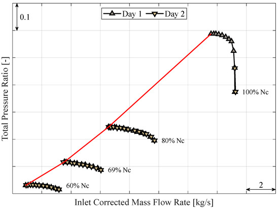
Figure 15.
TPR characteristics recorded over two different test days with the stall line shown in red.
Since the adaptable fan casing was designed to replace the aluminum casing to incorporate different flowpath geometries, it was important to compare the aerodynamic performance between these two configurations. An additional speedline was recorded at 90% Nc for comparison purposes. The TPR is similar between builds, especially at 80% Nc and 90% Nc. The most significant change appears at 100% Nc. The choked part of the speedline was consistent between the two fan casings; however, a significant departure begins at flow rates lower than the peak efficiency point. There are two important distinctions between the AM casing flowpath and the aluminum one. The first is the tip clearance. The tip clearance was not kept constant over different builds. The second is the contour of the casing. After inspecting the aluminum fan casing with a coordinate measuring machine, it was determined that there were small differences in the flowpath geometry. The abradable layer incorporated into the aluminum fan casing that surrounds the rotor was different compared to the equivalent region on the 3D printed inserts. There were noticeable areas where material had been rubbed away in previous tests before it was installed at Purdue. The abradable layer is also rougher compared to the PerFORM. The design of the AM inserts did not take these into account because they were based on nominal geometry from drawings. The largest driver of change was expected to be the result of the tip clearance change. For the aluminum fan casing, the measured tip clearance at 100% Nc was near 0.010″ (0.25 mm) compared to around 0.030″ (0.76 mm) for the AM fan casing. While both values are considered appropriate for this application, the difference is significant when comparing performance.
To determine how much of the change in TPR was a result of the tip clearance, the CFD model of this fan was run at the two measured tip clearance values. Dai’s thesis provides additional insight into the details of the computational model [16]. The CFD 100% Nc speedlines were solved using steady Reynolds-Averaged Navier–Stokes (RANS) equations in ANSYS CFX. The change in TPR between both clearance models was applied to the AM fan casing at the high loading points to predict what the performance likely would have been at a tighter tip clearance. Figure 16 shows the TPR characteristics for the AM fan casing, the aluminum fan casing, and the AM fan casing with the CFD correction applied. By accounting for the predicted tip clearance effects, the new speedline more closely matches the aluminum fan casing performance. No conclusions can be made regarding the difference in stalling mass flow rate because steady RANS computations are not reliable in predicting the mass flow rate at which stall will occur.
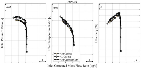
Figure 16.
Comparison of the 100% Nc characteristics for the AM casing, AL casing, and AM casing with the applied CFD correction.
The differences in aerodynamic performance between all three datasets were compared and the relative error, , is displayed in Table 5. The AM casing data with and without the CFD correction applied were compared to the aluminum casing data. The errors were evaluated at three different loading conditions; peak efficiency, high loading, and near stall. Only the relative errors are presented because the performance parameters are proprietary. They were calculated based on Equations (3)–(5), where refers to the efficiency. For the majority of the operating points, the CFD-corrected AM casing data has a lower value for the relative error. Correcting the data using CFD was effective in reconciling the difference that arose from the change in tip clearance.

Table 5.
Relative error between the AM fan casing and the aluminum fan casing at three relevant operating conditions.
4. Discussion
The new adaptable fan casing presents an excellent opportunity for future studies that incorporate changes to the surrounding fan flowpath. The inserts can be quickly exchanged and manufactured in a cost-effective way using the PerFORM and SLA. It is conceivable to print and test a new design in the span of one month, which would be unreasonably difficult if using metal 3D printing or traditional machining. Furthermore, aerodynamic performance was not significantly impacted by the implementation of the plastic compared to the metal.
A future improvement to the insert design would be to alleviate the corresponding stress concentration at the aft end of each insert. A geometric feature is required for correct alignment of the inserts; however, it may be possible to remove the apex of the notch, while maintaining a groove for the alignment pin. In theory, this would eliminate the stress concentration in this region. Additionally, the stress analysis should be repeated for extensive flowpath changes that might extend the operability of the fan. If higher operating temperatures are anticipated, they would need to be included in the analysis.
Future studies with the AM fan casing assembly should be parametric in nature to make full use of the benefits of AM. The best use case for the assembly is to experimentally test flowpath changes to determine the importance of design variables. The overall assembly concept was inspired by casing treatments, which often have numerous design variables. Using the PerFORM plastic, three or four sets of inserts may be manufactured and tested for the same price as a single traditionally machined fan casing. Casing treatments are not the limit; any proposed change to the geometry surrounding the rotor within reason can theoretically be implemented in experimental design studies. For example, researchers may choose to incorporate different contouring, or a “wavy wall” structure.
5. Conclusions
A novel fan casing assembly was designed and evaluated to significantly enhance the capability of future casing treatment research at Purdue University’s Fan Research Facility. The assembly is built around six AM inserts made of an advanced high-temperature ceramic-like thermoset plastic. The plastic offers acceptable build tolerance with outstanding lead time, cost, and geometric complexity compared to traditionally machined metal fan casings. To ensure the robustness of the inserts, a computational analysis method was outlined and performed. A design challenge associated with the AM material was the significant changes in mechanical properties at elevated temperatures. Furthermore, the material’s fracture state (ductile vs. brittle) is ambiguous, creating the need for a combined analysis.
The analysis method was validated because the AM fan casing was successfully tested all the way to stall at 100% Nc (the highest thermal load and the most strenuous mechanical load) without any evidence of distress or component failure. The 1D analysis provided a consistent prediction compared to the 2D and 3D analyses in regions of the inserts where there were no features (fillets, notches, etc.).
The assembly was tested successfully, and a baseline dataset was acquired that will allow for comparisons to treated casings manufactured with the same material. Testing with the casing showed excellent robustness against day-to-day variation, and the aerodynamic performance was also comparable. At 100% Nc, the performance differences were tied to the tip clearance, and are unlikely to be related to the implementation of the plastic casing. The possibilities of casing treatments and flowpath geometries are expansive as a result of this new fan casing, and designs can be quickly and cost-effectively implemented. Furthermore, research performed in the future will be of high quality as a result of the outcomes of this paper.
Author Contributions
Conceptualization, A.C. and N.L.K.; methodology, A.C. and N.L.K.; validation, A.C.; formal analysis, A.C.; investigation, A.C.; resources, N.L.K.; data curation, A.C.; writing—original draft preparation, A.C. and N.L.K.; writing—review and editing, A.C. and N.L.K.; visualization, A.C.; supervision, N.L.K.; project administration, N.L.K.; funding acquisition, N.L.K. All authors have read and agreed to the published version of the manuscript.
Funding
The authors would like to acknowledge the Office of Naval Research for the financial support in developing the adaptable fan casing under grant numbers N00014-19-1-2561 and N00014-19-1-2277.
Data Availability Statement
The datasets presented in this article are not readily available because fan aerodynamic performance is proprietary information. Requests to access the datasets should be directed to nkey@purdue.edu.
Acknowledgments
Throughout the design process, Honeywell engineers provided helpful advice, which is gratefully acknowledged and allowed for successful implementation. Furthermore, Honeywell’s donation of fan hardware and other auxiliary fan components was appreciated. Additionally, the authors would like to acknowledge Yuning Dai, Andrew Bedke, and Charlotte Gump, who were all instrumental in collecting the aerodynamic performance data required to validate the AM casing design. Yuning’s CFD models were especially helpful in reconciling the test data, and her computational best practices are greatly appreciated.
Conflicts of Interest
The authors declare no conflicts of interest.
References
- Kellner, T. Mind Meld: How GE And A 3D-Printing Visionary Joined Forces; General Electric: Evendale, OH, USA, 2017. [Google Scholar]
- Benzinger, A. Siemens Achieves Breakthrough with 3D Printed Gas Turbine Blades; Siemens: Worcester, UK, 2017. [Google Scholar]
- Novotny, V.; Spale, J.; Stunova, B.B.; Kolovratnik, M.; Vitvarova, M.; Zikmund, P. 3D Printing in Turbomachinery: Overview of Technologies, Applications and Possibilities for Industry 4.0. In Proceedings of the ASME Turbo Expo 2019: Turbomachinery Technical Conference and Exposition, Phoenix, AZ, USA, 17–21 June 2019. [Google Scholar] [CrossRef]
- Conner, B.P.; Manogharan, G.P.; Martof, A.N.; Rodomsky, L.M.; Rodomsky, C.M.; Jordan, D.C.; Limperos, J.W. Making Sense of 3-D Printing: Creating a Map of Additive Manufacturing Products and Services. Addit. Manuf. 2014, 1, 64–76. [Google Scholar] [CrossRef]
- Clement, J.T.; Coon, A.T.; Key, N.L. Development of an Additively Manufactured Stationary Diffusion System for a Research Aeroengine Centrifugal Compressor. In Proceedings of the Turbomachinery Technical Conference and Exposition, London, UK, 24–28 June 2024. [Google Scholar]
- Green, J.C. A Manufacturing Process to Implement Transonic Compressor Endwall Casing Treatments. Masters’s Thesis, Naval Postgraduate School, Monterey, CA, USA, 2021. [Google Scholar]
- Jones, M.B. Experimental and Computational Analysis of Advanced Casing Treatments in a Transonic Compressor. Masters’s Thesis, Naval Postgraduate School, Monterey, CA, USA, 2022. [Google Scholar]
- Cusator, A.C.; Brown, W.J.; Dai, Y.; Bedke, A.M.; Key, N.L. Development of a Transonic Fan Research Facility Focused on Casing Treatments and Inlet Distortion Effects. In Proceedings of the ASME Turbo Expo, London, UK, 24–28 June 2024. [Google Scholar]
- Gibson, I.; Rosen, D.W.; Stucker, B.; Khorasani, M.; Rosen, D.; Stucker, B.; Khorasani, M. Additive Manufacturing Technologies; Springer: New York, NY, USA, 2021. [Google Scholar]
- Adkins-Rieck, R. Additive Manufacturing for Aerodynamic Diffuser Designs in a Centrifugal Compressor. Master’s Thesis, Purdue University, West Lafayette, IN, USA, 2018. [Google Scholar]
- Meier, M.A.; Gooding, W.J.; Fabian, J.; Key, N.L. Considerations for Using Additive Manufacturing Technology in Centrifugal Compressor Research. J. Eng. Gas Turbines Power 2020, 142, 031018. [Google Scholar] [CrossRef]
- Young, W.C.; Budynas, R.G.; Sadegh, A.M. Roark’s Formulas for Stress and Strain; McGraw-Hill: New York, NY, USA, 2002. [Google Scholar]
- Schmid, S.R.; Hamrock, B.J.; Jacobson, B.O. Fundamentals of Machine Elements; CRC Press: Boca Raton, FL, USA, 2014. [Google Scholar]
- ANSYS Mechanical User’s Guide; ANSYS Inc.: Canonsburg, PA, USA, 2024.
- Cusator, A. Leveraging Additive Manufacturing in a Newly Designed and Commissioned Transonic Fan Research Facility. Ph.D. Thesis, Purdue University, West Lafayette, IN, USA, 2024. [Google Scholar]
- Dai, Y. Modelling Considerations for a Transonic Fan. Master’s Thesis, Purdue University, West Lafayette, IN, USA, 2022. [Google Scholar]
Disclaimer/Publisher’s Note: The statements, opinions and data contained in all publications are solely those of the individual author(s) and contributor(s) and not of MDPI and/or the editor(s). MDPI and/or the editor(s) disclaim responsibility for any injury to people or property resulting from any ideas, methods, instructions or products referred to in the content. |
© 2024 by the authors. Licensee MDPI, Basel, Switzerland. This article is an open access article distributed under the terms and conditions of the Creative Commons Attribution (CC BY) license (https://creativecommons.org/licenses/by/4.0/).