Article

Flap and Wing Dynamics for a Light Sport Aircraft Analysis Using a Topological Model

1
Department of Mechanical Engineering, Faculty of Mechanical Engineering, Transylvania University of Brasov, B-dul Eroilor 29, 500036 Brasov, Romania
2
Technical Sciences Academy of Romania, B-dul Dacia 26, 030167 Bucharest, Romania
3
Department of Mathematics and Informatics, Transylvania University of Brasov, B-dul Eroilor 29, 500036 Brasov, Romania
4
Academy of Romanian Scientist, Ilfov Street, No. 3, 050045 Bucharest, Romania
*
Author to whom correspondence should be addressed.
Appl. Sci. 2024, 14(18), 8531; https://doi.org/10.3390/app14188531
Submission received: 24 August 2024 / Revised: 14 September 2024 / Accepted: 18 September 2024 / Published: 22 September 2024
(This article belongs to the Section Aerospace Science and Engineering)

Abstract

:

Featured Application

This paper proposes a method to determine the dynamic response of a planar mechanism with a practical application to a flap and wing control mechanism of a light sport aircraft. For this, a topological model and its related theory are used.

Abstract

This paper presents a more general method to study the dynamic behavior of a planar mechanism with joints. To do this, Graph Theory is used. A topological description is presented based on which a corresponding graph is attached to any mechanism. This method can be used for both kinematic and dynamic study in the same model, and many of the descriptors used in kinematic analysis can also be used for dynamic analysis. As a final result, the motion equations of the studied mechanical system can be obtained. An application is made to a flap and wing control system of a light sport aircraft. The graph associated with the mechanism first used to determine the field of velocities and accelerations of the mechanism elements is then used to obtain the motion equation for the control system. In this way, Graph Theory proves useful for the parallel study of both the kinematic and dynamic study of such problems.

1. Introduction

Strongly developed towards the middle of the last century, Graph Theory first proved its usefulness in the field of electrical networks, allowing for the automation of the calculation of these networks under the assumptions of Kirckhof’s laws, and then it proved its usefulness in other branches of engineering as well [1]. The methodology made it possible to systematize the description and algorithmize the analysis methods of electric circuits. In this approach, each real circuit is associated with a graph. Calculation algorithms and numerical procedures can be formulated based on theorems from Graph Theory [2,3]. The advantages offered by this method also inspired mechanical engineers. They developed the known methods in the study of the mechanism, within the kinematic and dynamic analyses.
For the synthesis of a mechanism required for some engineering applications, well-known methods from the theory of mechanisms are generally applied and need the deep involvement of the designer. However, other methods have been developed that allow for the algorithmization of certain operations such as with the application of Graph Theory [4]. In a graph associated with the mechanism, a tree and independent kinematic chains are identified. Based on this graph, an extended matrix is generated [5], which structurally characterizes a complete mechanism. Thus, information about a mechanism becomes easily accessible and allows for a topological and dimensional synthesis of the considered mechanism. The obtained results show that this matrix method, based on Graph Theory, is a useful and flexible tool for the study of mechanisms and MBSs.
Another approach method based on Lie groups was developed and used for the dynamic analysis of robots [6]. In this description, the information is entered into a matrix. In this way, easy mathematical manipulation is possible, and simulation, analysis or identification algorithms can be built. The advantages of the proposed method are illustrated by an application on two robots, one with 7 degrees of freedom and the other with 16.
The formalism proposed by Graph Theory has proven to be a powerful tool for MBS analysis [7]. Graphs represent a way of describing a mechanism that facilitates study and analysis. Problems arise related to the number of independent cycles, isomorphism detection or structural decomposition. Based on this description, a structural and kinematic analysis of the mechanisms can be made. The problems studied are illustrated by examples. A suggested example of studying mechanisms using structural graphs is presented in [8]. A comparison is made between different types of graphs that can be associated with a mechanism. Based on the current state of development of Graph Theory, a hybrid mechanism with spatial motion is analyzed, from the point of view of the spatial motion capacity [9]. The non-singularity condition of the studied mechanism is analyzed. The study of moving capability, degree of freedom and singularity of mechanism was found to be a very powerful tool in Graph Theory [10]. With the help of these notions, 324 mechanisms are analyzed and the advantages of using and automating the method are noted [11]. The use of the associated graph for the analysis of mechanisms used in engineering practice is presented in [12,13,14,15]. For the creative, conceptual or structural analysis and synthesis of mechanical devices, of major importance is the construction of the atlas of kinematic chains (with mobile and fixed elements). It is obtained with different methods, among which the associated graph method stands out for its simplicity [16,17].
Practical applications have determined the use of modern means of analysis in the theory of mechanisms. Thus, an exhaustive and advantageous method of preliminary analysis and design of an innovative mechanism for reflector antennas, having its origins in Graph Theory, is described in [18]. With this method, the calculation can be automated and an optimal solution can be obtained for the formulated problem. A robotic mechanism is also being studied in this way [19]. A hierarchy of existing connections between elements of the robotic mechanism is generated. Based on the hierarchy and the associated graph, an analysis of the system can be performed. The presented method is exemplified when calculating a manipulator with two degrees of freedom. The same methods are used in the design of a windshield wiper mechanism [20]. To optimize the solution, the constraints are defined and the objective functions are specified. In this way, an optimal solution can be obtained from an engineering point of view.
Another approach that closely resembles the topological approach of a planar mechanism is Assur Graphs. Tabular information about the structure of the mechanism is used in this method. The method can be applied to all planar mechanisms. Using the well-known Assur Groups, Ref. [21] proposes a mathematical method for analyzing and determining the dynamic response of planar mechanisms. Nowadays, all these study methods have come to use sophisticated optimization methods and topological analysis. In this way, an optimal version of the project can be determined. An original method is presented in [22]. A genetic algorithm is used for topological synthesis. Some examples were given that illustrated the proposed method.
It can be mentioned that the engineering practice failed to impose a unitary approach for the study of complex mechanisms with several kinematic chains. To solve these types of problems, several types of approaches are used to solve these types of problems, though all of them need the information provided by the topological analysis of the system. An attempt to systematize and unify the various models is attempted in [23].
The analysis of an exoskeleton using the topological description is presented in [24]. The proposed model is validated using the commercial Adams 2020 software. An application that values the use of structural graphs is described in [25], a paper that also makes a theoretical development of the methods used. Knowledge Graph represents an essential notion in Graph Theory, but its inherent incompleteness and shortfalls limit and influence its performance in several areas. The method proposed in [26], Knowledge Graph Reasoning, proposes to improve these problems by extracting new knowledge from existing knowledge. This presentation can provide powerful advantages in using Graph Theory. Concrete applications in the real word, developed using Graph Theory, can be found in [27,28,29,30]. The study of gear mechanisms is performed in [31,32], and recent theoretical results in the field of theoretical development can be found in [33,34].
Introducing well-studied mathematical methods to facilitate the description and analysis of multibody systems (MBSs) has been a concern of engineers for a long time. In addition to the classical methods of mathematics, widely used in any problem related to MBS kinematics or dynamics, new results provided by Graph Theory or topology were used. As an example, a design method for parallel mechanisms with reduced mobility was developed and presented in [35]. A new category of MBSs is thus introduced, namely mechanisms with variable topology. Based on them, a theoretical foundation is proposed for innovative approaches in the synthesis stage of parallel mechanisms with reduced mobility. Thus, mechanisms with variable topology have the advantage of being able to offer a multitude of design functions using only a single mechanism. By changing its topology, different response functions are achieved. The topology can be modified in several ways: by intrinsic constraints, by changing the geometry and by introducing external constraints. Some basic requirements for such mechanisms are presented in [36]. A combination of Graph Theory with topological analysis is performed in [37]. Seventeen new parallel mechanisms are thus studied using associated topological graphs. Parallel mechanism with variable topology is a widely discussed topic in the field, mainly because of possible practical applications. Genetic synthesis in topological description represents the new direction of research in the field of mechanisms with variable topology. In [38], this direction is described in detail and the suggested examples illustrate the authors’ approach. To facilitate the description of a mechanism or MBS, topological methods have been developed to satisfy the need to abstract some stages of solving the problem. Examples showing the effectiveness of this approach are presented in [39,40]. The use of topological optimization of some mechanisms, to make their description more efficient, is used in [41,42]. More complicated problems involving the use of additional parameters and specific applications are studied in [43,44,45,46,47,48,49]. Attempts to describe the dynamic behavior based on some topological formalism of such systems are presented in [50,51,52].
This paper introduces new methods of analysis of mechanisms, to determine their response in different loading and operating situations, that have been present for a long time and illustrated in the literature. Among these methods, Graph Theory and topological analysis were distinguished. By applying these methods, it is possible to simplify the description of the structure and geometry of a mechanism. The use of these tools allowed for the development of several methods of mechanism analysis. In this paper, we will use the results from Graph Theory, but with another method of construction of associated graphs. In this description, a graph loop associated with the mechanism essentially represents a closed vector contour. The nodes of the graphs are the contact points that ensure the connection between the different elements of the mechanism. In this way, it is possible to simplify the description of the kinematics and dynamics of such a mechanism, and the process can be algorithmized. The advantages of such an approach become visible in the case of mechanisms that contain several kinematic chains.
In this work, we dealt with the unitary description, using Graph Theory, of a mechanism designed for the control system of a light plane. In this way, with a single description of the mechanism realized through the associated graph, it allows for the algorithmization of obtaining the response in time, both at the kinematic and dynamic levels. In this way, the designer can simplify the work of analyzing such a mechanism.

2. Graph Associated with a Planar Mechanism

In [15], a method for associating a graph with a mechanism is presented so that an algorithm for kinematic analysis of a mechanism can be developed. In this paper, there is a development of this method and the dynamic study of such a system.
The use of Graph Theory in the field of Electrical Circuits has proven to be a success. Based on the experience gained in this field, the obtained results can be extended to the kinematic analysis of a mechanism. Using Graph Theory to describe the topological structure of the mechanism, an algorithm can be developed to determine the angular velocities and accelerations of each element of the bar mechanism.
Below is a description of the algorithm for the kinematic and dynamic analysis of such mechanisms.

2.1. The Kinematic Equivalent Mechanism and Associated Graph

In the first step, the real mechanism will be replaced by an equivalent kinematic mechanism. The elements of this multibody system are bars and plates.
Our goal is to operate only with mechanisms consisting of bars, connected to each other by joints. To achieve this goal, we will have to replace the plate elements with bar elements, which first respects the geometry of the mechanism and then ensures the rigidity of the considered plate element. The idea is to have a similar mechanism where the mechanical behavior is the same, which is called a kinematically equivalent mechanism. To achieve this, the following transformations can be made:
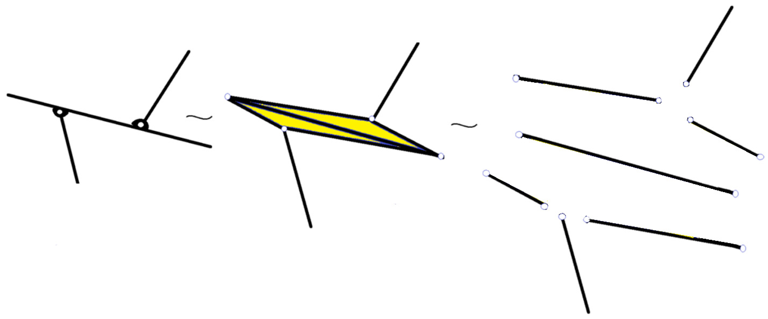
  • A two-dimensional plane element (Figure 1 and Figure 2) can be replaced by a structure with bars connected by joints in a rigid connection. So, the plate can be replaced with a rigid structure with bars.
  • A beam element with several joints along its length can be considered a polygon, made by bars with joints at the corners (in Figure 3, triangles). For example, if on a line there are three collinear joints, this is equivalent to a triangle, with two angles measuring 0° and the third 180°.
  • To connect different points where the joints connect to the ground (a fixed element), additional bar-type elements are introduced to obtain a polygon. Afterwards, one of these elements is removed. These newly introduced elements have zero angular velocities and angular accelerations.
By following these operations, a planar mechanism is obtained, consisting only of bars connected by joints but which is equivalent, from a mechanical point of view, to the mechanism studied. This new mechanism retains the geometry and functionality of the original mechanism. Now, by associating branches to bars and nodes to joints, it is possible to obtain the graph associated with the mechanism (a similar procedure as seen in circuit theory) [19].
The application of these considerations to the mechanism presented in Figure 1 results in the mechanism shown in the same figure with the associated graph subsequently presented in Section 2.2.

2.2. Incidence Matrix

By attaching to each bar element a vector, with the end in one joint and the top in the other, and taking for each branch the direction of travel given by the direction of the vector thus constructed, the oriented graph from Figure 4 is obtained.
Let r + 1 be the number of nodes and s the number of branches of the obtained graph. The complete incidence matrix A = ε i j of the associated graph is defined as a matrix having the dimensions (r + 1) × s (s > r) where
  • ε i j = 1 if branch j is incident at node i and comes out of the node;
  • ε i j = 1 if branch j is incident at node i and enters the node;
  • ε i j = 0 if branch j is not incident at node i.
These operations offer us a matrix A that looks like the following:
n o d e s \ b r a n c h e s 1   2    3 s A = 1 2 r + 1 ε 11 ε 12 ε 13 ε 1 s ε 21 ε 22 ε 23 ε 2 s ε r + 1 , 1 ε r + 1 , 2 ε r + 1 , 3 ε r + 1 , s
where
ε i j 1 ,   0 ,   1 ; i = 1 , 2 , , r + 1 ; j = 1 , 2 , , s .
A few examples will clarify the associated graph and the incidence matrix problem below.
Example 1. 
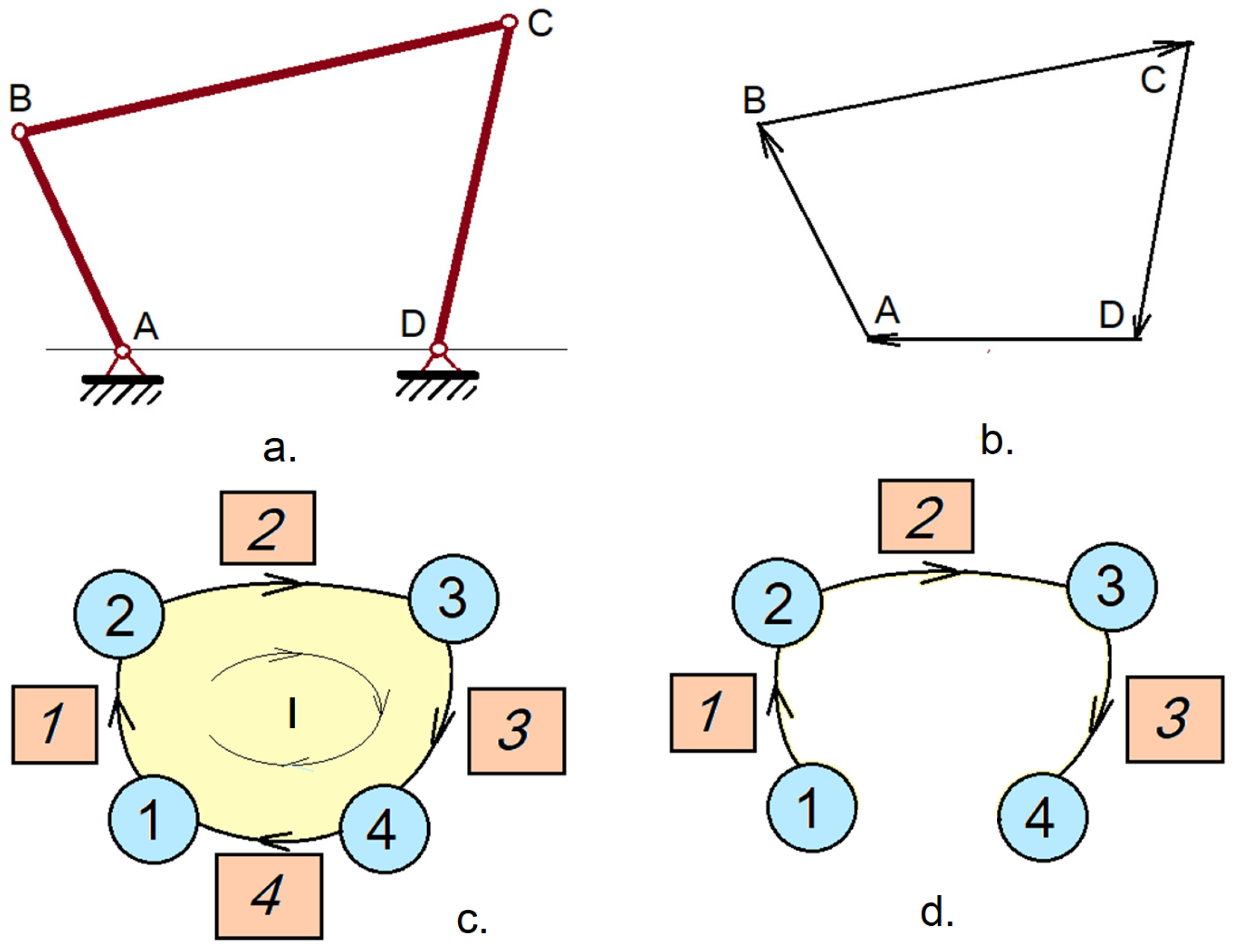
The associated graph of the four-bar linkage (Figure 4a) is shown in Figure 4c. Figure 4b shows the vector contour that defines the single loop of the mechanism. The extended incidence matrix, if using the notation in Figure 4c, is as follows:
n o d e s \ b r a n c h e s 1     2     3     4 A = 1 2 3 4 1 0 0 1 1 1 0 0 0 1 1 0 0 0 1 1
The matrix of the fundamental loops (in our case, only one loop) is
c y c l e \ b r a n c h e s     1 2 3 4 B f = 1   1 1 1 1  
Example 2. 
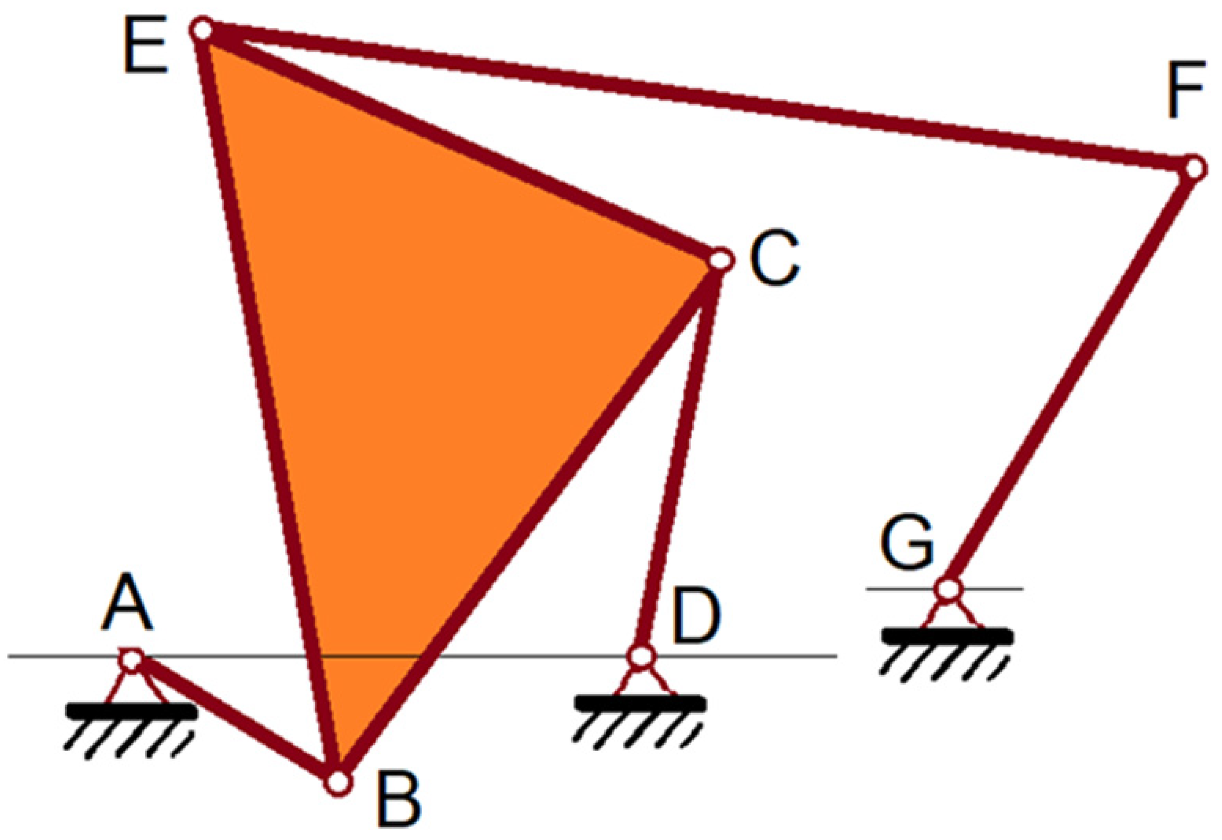
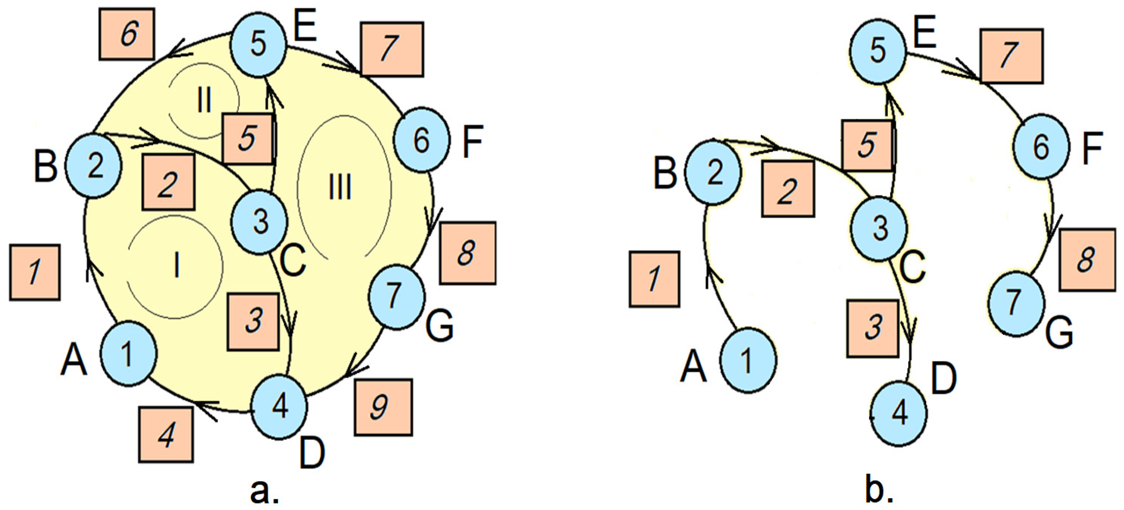
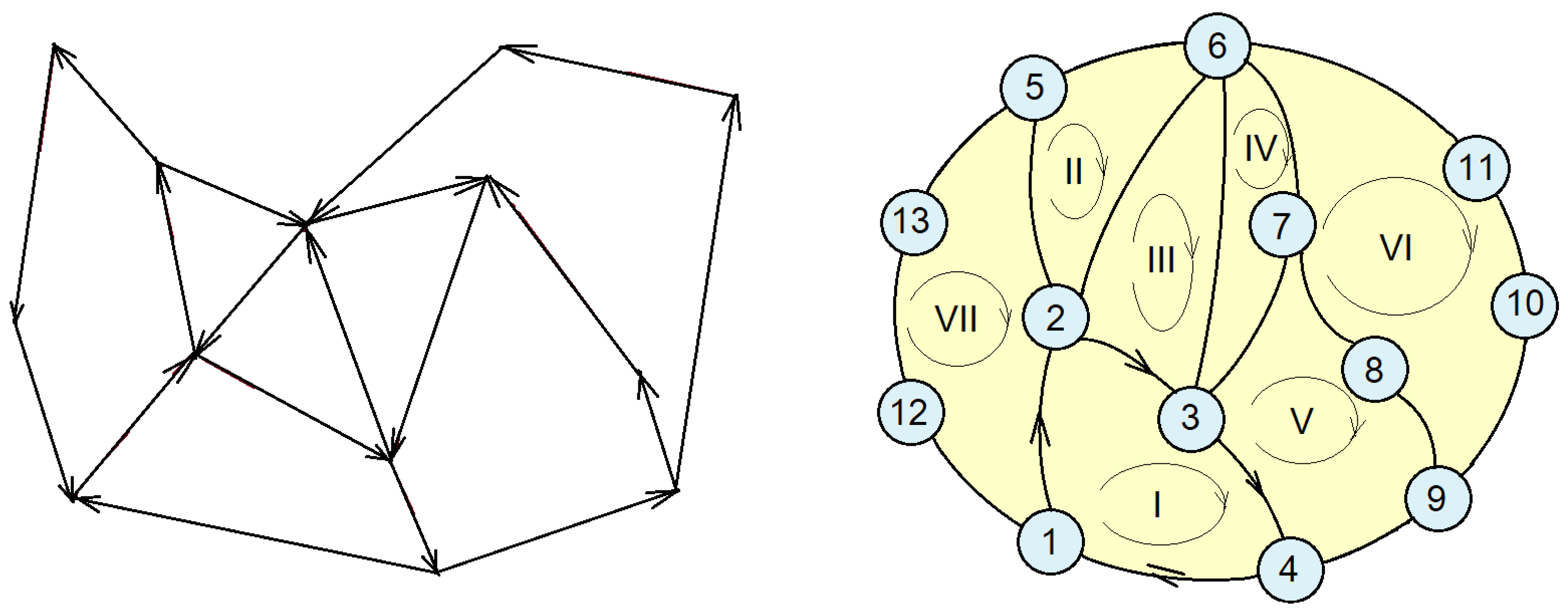
A slightly more complex mechanism is shown in Figure 5. Three independent loops are presented in Figure 6. The associated graph and tree are attached to this mechanism (Figure 7).
The extended incidence matrix is as follows:
n o d e s \ b r a n c h e s 1     2     3     4    5    6    7   8    9 A = 1 2 3 4 5 6 7 1 0 0 1 0 0 0 0 0 1 1 0 0 0 1 0 0 0 0 1 1 0 1 0 0 0 0 0 0 1 1 0 0 0 0 1 0 0 0 0 1 1 1 0 0 0 0 0 0 0 0 1 1 0 0 0 0 0 0 0 0 1 1
The matrix of the fundamental loops is
c y c l e \ b r a n c h e s    1 2   3   4   5 6 7 8 9 B f = 1      1 1 1 1 0 0 0 0 0 0 1 0 0 1 1 0 0 0 0 0 1 0 1 0 1 1 1
Example 3. 
A planar mechanism that has a plate with multiple joints is presented in Figure 8 (showing the mechanism and the equivalent mechanism). The associated graph is shown in Figure 9.
Example 4. 
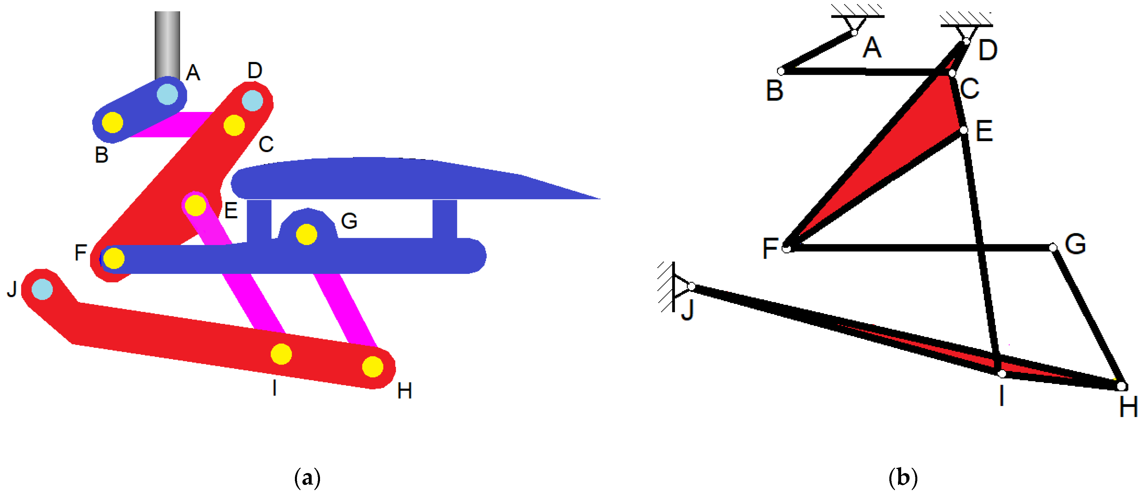
The studied mechanism is shown in Figure 10a and the kinematical representation in Figure 10b and Figure 11.
n o d e \ b r a n c h     1    2     3     4     5     6     7     8    9   10   11   12   13   14   15 A = 1 2 3 4 5 6 7 8 9 10 1 1 0 0 0 0 0 0 0 0 0 0 0 0 0 0 1 1 0 0 0 0 0 0 0 0 0 0 0 0 0 0 1 1 1 0 1 0 0 0 0 0 0 0 0 1 0 0 1 0 1 0 0 1 0 0 0 0 0 0 0 0 0 0 1 1 0 0 0 1 0 0 0 0 1 0 0 0 0 0 0 1 0 0 1 1 0 0 0 0 0 0 0 0 0 0 0 0 0 0 1 1 0 0 0 0 0 0 0 0 0 0 0 0 0 0 1 1 1 0 0 0 0 0 0 0 0 1 0 0 0 0 1 0 1 0 0 0 0 0 0 0 1 1 0 0 0 0 1 0
Now, by suppressing a line in the matrix defined by Equation (3) (having the rank r), the reduced incidence matrix is obtained A a :
n o d e \ b r a n c h    1     2     3     4     5     6     7    8 9 10   11   12   13 14 15 A a = 1 2 3 4 5 6 7 8 9 1 1 0 0 0 0 0 0 0 0 0 0 0 0 0 0 1 1 0 0 0 0 0 0 0 0 0 0 0 0 0 0 1 1 1 0 1 0 0 0 0 0 0 0 0 1 0 0 1 0 1 0 0 1 0 0 0 0 0 0 0 0 0 0 1 1 0 0 0 1 0 0 0 0 1 0 0 0 0 0 0 1 0 0 1 1 0 0 0 0 0 0 0 0 0 0 0 0 0 0 1 1 0 0 0 0 0 0 0 0 0 0 0 0 0 0 1 1 1 0 0 0 0 0 0 0 0 1 0 0 0 0 1 0 1
Considering the representation in Figure 12, we can choose a tree (Figure 13) and reorder it A
A = [ A t A l ]
so that the columns of A t correspond to the branches of the tree, and the columns of A l correspond to the junctions that can be obtained via the matrix of fundamental loops.
n o d e \ b r a n c h     2     3     4     5    8 10   11   12   13    1     6     7     9   14 15 A a r e o r d = 1 2 3 4 5 6 7 8 9 1 0 0 0 0 0 0 0 0 1 0 0 0 0 1 1 1 0 0 0 0 0 0 0 0 0 0 0 0 0 0 1 1 1 0 0 0 0 0 0 0 1 0 0 0 0 0 1 0 0 0 0 0 0 1 1 0 1 0 0 0 0 0 1 0 1 0 0 0 0 1 0 0 0 0 0 0 0 0 0 1 1 0 0 0 0 1 0 0 0 0 0 0 0 0 0 1 1 0 0 0 0 0 0 0 0 0 0 0 0 0 0 1 1 0 0 0 0 1 0 0 0 0 0 1 0 0 0 1 0 0 0 0 0 0
n o d e \ b r a n c h    2     3     4     5   8   10   11   12   13 A t = 1 2 3 4 5 6 7 8 9 1 0 0 0 0 0 0 0 0 1 1 0 0 0 0 0 0 0 0 1 1 1 0 0 0 0 0 0 0 1 0 0 0 0 0 0 0 0 0 1 0 1 0 0 0 0 0 0 0 0 1 1 0 0 0 0 0 0 0 0 1 1 0 0 0 0 0 0 0 0 1 1 0 0 0 0 1 0 0 0 1
n o d e \ b r a n c h    1     6     7     9 14 15 A l = 1 2 3 4 5 6 7 8 9 1 0 0 0 0 1 0 0 0 0 0 0 0 0 1 0 0 0 1 1 0 1 0 0 0 1 0 0 0 0 0 0 1 0 0 0 0 0 0 0 0 0 0 0 0 0 1 0 0 0 0 0 0 0
In Graph Theory, the complete matrix of fundamental loops is defined as the matrix B a = [ b i j ] , where
b i j = 1 if the branch j is part of the loop i having a positive orientation;
b i j = 1 if side j is part of the loop i having a negative orientation;
b i j = 0 if branch j is not part of loop i.
l o o p s \ b r a n c h e s 1 2 3 s B a = 1 2 n b η 11 η 12 η 13 η 1 s η 21 η 22 η 23 η 2 s η n b + 1 , 1 η n b + 1 , 2 η n b + 1 , 3 η n b + 1 , s
Here, η i j 1 , 0 , 1 ;   i = 1 , 2 , , n b ;   j = 1 , 2 , , s ; and n b represents the total number of graph loops. According to Graph Theory [1,2,3], the rank of the matrix B a is sr. This matrix contains redundant information (some rows, describing a loop, can be obtained as a linear combination of other rows). The matrix B f , with the rank sr, considering sr linear independent rows, is the complete matrix B a . B f can be obtained using the relation
B f = [ [ A t 1 A l ] T E ]
Given our mechanism, the matrix of fundamental loops is [53]
c y c l e \ b r a n c h     2     3 4    5    8 10 11 12      13      1     6      7     9    14    15 B f = 1 2 3 4 5 6 1 1 1 0 0 0 0 0 0 1 0 0 0 0 0 0 0 1 1 0 0 0 0 0 0 1 0 0 0 0 0 0 0 1 0 1 0 0 0 0 0 1 0 0 0 0 0 1 1 1 1 1 1 1 0 0 0 1 0 0 0 0 0 0 1 0 0 0 1 0 0 0 0 1 0 0 0 0 0 0 1 1 1 1 0 0 0 0 0 1
This matrix is not unique, depending on the chosen tree.

3. Kinematic Analysis of the Control Mechanism

We will perform a partition of B f , B f = [ B f u B f k ] made after a rearrangement of the columns of B f so that the matrix B f u corresponds to the elements of the first class and B f k to the elements of the second class.
c y c l e \ b r a n c h 3 4    5 6     7 8 10 11 12 13     14   15     1     2     9 B f r e o r d = 1 2 3 4 5 6 1 1 0 0 0 0 0 0 0 0 0 0 1 1 0 0 1 1 1 0 0 0 0 0 0 0 0 0 0 0 0 0 1 0 1 0 1 0 0 0 0 0 0 0 0 0 1 1 0 0 1 1 1 1 1 0 0 0 0 1 0 0 0 0 0 1 0 0 0 1 1 0 0 0 0 0 0 0 0 0 0 1 1 1 1 0 1 0 0 0
where
c y c l e \ b r a n c h     3 4    5   6     7 8 10 11 12 13     14   15 B f u = 1 2 3 4 5 6 1 1 0 0 0 0 0 0 0 0 0 0 0 1 1 1 0 0 0 0 0 0 0 0 0 0 1 0 1 0 1 0 0 0 0 0 0 1 1 0 0 1 1 1 1 1 0 0 0 0 0 0 0 1 0 0 0 1 1 0 0 0 0 0 0 0 1 1 1 1 0 1
c y c l e \ b r a n c h     1     2      9 B f c = 1 2 3 4 5 6 1 1 0 0 0 0 0 0 0 0 0 1 0 0 0 0 1 0
In the following, we note that
\ D \ = \ D 1 D 2 D p \ = D 1 D 2 0 0 D p
which is a diagonal matrix, having on the diagonal the elements D1, D2, …, Dp.
The geometry of the structure will be defined using the following diagonal matrices of size s, having the elements in the order in which they are in the matrix of the fundamental loops rearranged:
  • \ L \ partitioned in \ L n \ (matrix of the length of bar elements with an unknown motion) and \ L c \ (matrix of the length of bar elements with a known motion)
\ L \ = \ L n \ 0 0 \ L c \
where
\ L n \ = \ l 3 l 4 l 5 l 13 l 14 l 15 \
and
\ L c \ = \ l 1 l 2 l 9 \
  • \ C \ , the matrix with the cosine of the angles made by the bars with the horizontal axis, partitioned in \ C n \ (unknown motion) and \ C c \ (known motion)
\ C \ = \ C n \ 0 0 \ C c \
where
C n = \ cos θ 3 cos θ 4 cos θ 5 cos θ 13 cos θ 14 cos θ 15 \
and
C c = \ cos θ 1 cos θ 2 cos θ 9 \
  • S , the matrix with the sine of the angles made by the bars with the horizontal axis, partitioned in \ S n \ (unknown motion) and \ S c \ (known motion)
\ S \ = \ S n \ 0 0 \ S c \
where
S n = \ sin θ 3 sin θ 4 sin θ 5 sin θ 13 sin θ 14 sin θ 15 \
and
S c = \ sin θ 1 sin θ 2 sin θ 9 \
We define the column vectors of size s as
ω = ω n ω c = ω 3 ω 4 ω 15 ω 1 ω 2 ω 9 ; ω 2 = ω n 2 ω c 2 = ω 3 2 ω 4 2 ω 15 2 ω 1 2 ω 2 2 ω 9 2 ; ε = ε n ε c = ε 3 ε 4 ε 15 ε 1 ε 2 ε 9
In subsequent calculus, it must be considered that ω 1 = ω 9 = 0 ; ε 1 = ε 9 = 0 ; with the elements 1 and 9 being fixed elements. In these formulas, we have denoted
l i —the length of the numbered element with i;
θ i —the angle made by the vector l ¯ i with the axis Ox of the global coordinate system xOy;
ω ¯ i —the angular velocity of the element numbered with i;
ε ¯ i —the angular acceleration of the element i.
By applying this theory, it is possible to obtain the unknown velocities and acceleration vectors as a function of the known vectors of the velocities and accelerations, with the relations
ω n = P n 1 P c ω c ,
and
ε n = P n 1 P c ε c + Q n ω n 2 + Q c ω c 2 .
where
P s n = B f n L n S n ; P c n = B f n L n C n ; P s c = B f c L c S c ; P c c B 0 f c L c C c ,
and
P n = P s n P c n ; P c = P s c P c c ; Q n = P c n P s n ; Q c = P c c P s c ,
Using the results obtained by using Graph Theory, an algorithm for obtaining the field of the velocities and accelerations was thus established (see [15]).
The flap control mechanism must ensure the improvement of the dynamic behavior of the light aircraft. It must also allow steering angles greater than 40°. These are required in the case of take-offs or landings made over short distances and, of course, faster. It must also ensure an increased load capacity, as well as the ability to operate the airplane in critical flight conditions with low manufacturing costs [54,55,56,57,58,59,60]. The light aircraft proposed in this paper falls into the light sport aircraft category, for sport and leisure aviation. It has a two-seat capacity and hingeless curved flaps mounted on the wings. Maximum take-off weight is estimated to be 900 kg. It must ensure a cruising speed of 450 km per hour and a maximum flight height of 5000 m.
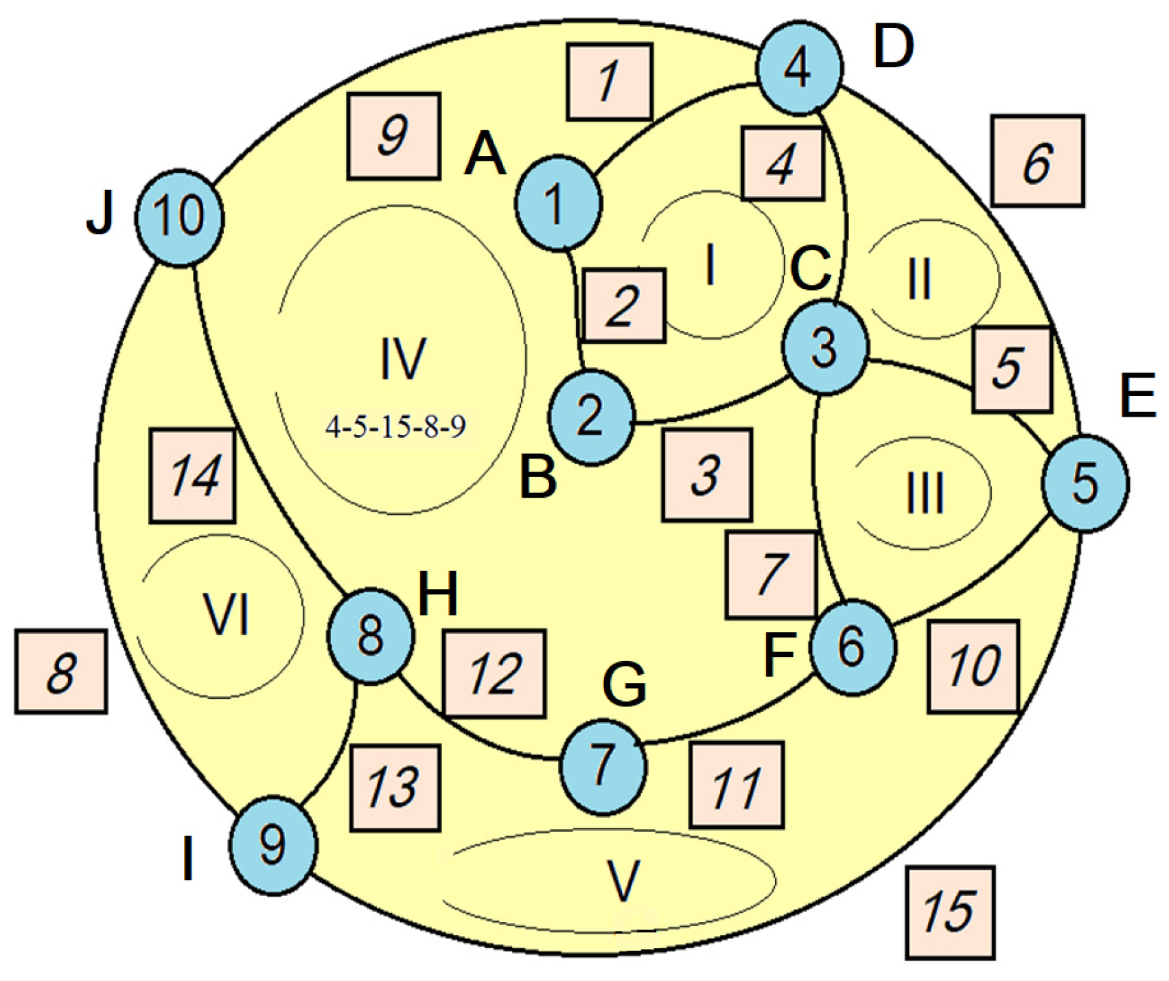
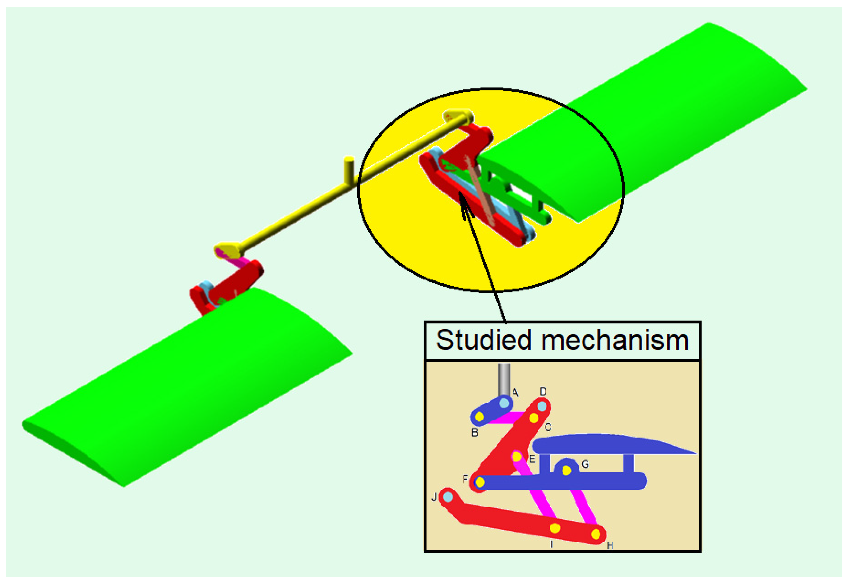
The kinematic sketch of the mechanism is presented in Figure 14 where the studied mechanism can be identified in Figure 10. The associated graph was built (Figure 12) and a tree was identified (Figure 13). So, it is possible to construct the fundamental loop matrix (Equation (11)) and to obtain the kinematic parameter Equations (25) and (26).

4. Dynamic Analysis

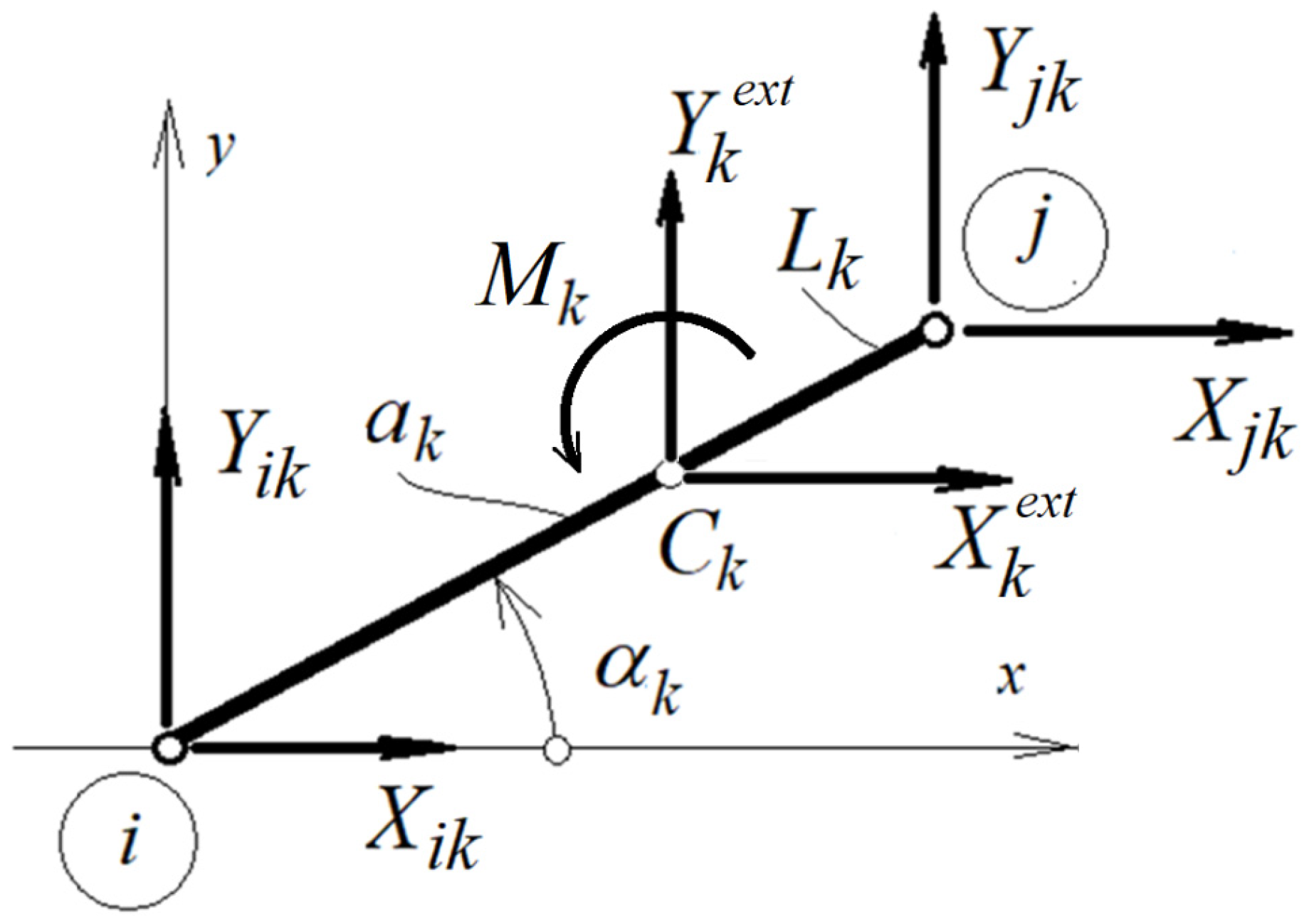
In Section 2, a mechanism with joints and a planar motion was associated with a planar mechanism consisting only of bars. From a mechanical point of view, the two mechanisms are equivalent. To perform a dynamic analysis of the mechanism, the motion equations of each bar that compose the equivalent mechanism will be written, and then, taking into account the liaison conditions, the motion of the entire assembly will be obtained. Figure 15 shows a bar with joints at both ends, and its motion equations will be written in the center of mass of the bar.
By considering the free body diagram for one element, it is possible to write the motion equations for a single bar element, numbered k:
m k a C k x = X k i + X k j + X k e x t ; m k a C k y = Y k i + Y k j + Y k e x t ; J k ε k = X k i a k sin α k X k j L k a k sin α k Y k i a k cos α k + Y k j L k a k cos α k + M k e x t ,
or
m k 0 0 0 m k 0 0 0 J k a k x a k y ε k = X k i + X k j Y k i + Y k j X k i a k sin α k X k j L k a k sin α k Y k i a k cos α k + Y k j L k a k cos α k + X k e x t Y k e x t M k e x t ;
or in a symbolic form
m k a k = Q k l i a i s o n + Q k e x t ,
where the following is denoted:
m k = m k 0 0 0 m k 0 0 0 J k ; a k = a k x a k y ε k ; Q k e x t = X k e x t Y k e x t M k e x t ,
Q k l i a i s o n = X k i + X k j Y k i + Y k j X k i a k sin α k X k j L k a k sin α k Y k i a k cos α k + Y k j L k a k cos α k .
The mass center accelerations are obtained by one of the following relations:
a C k x = a i x ε k b k y ω k 2 b k x ; a C k x = a j x ε k L k b k y ω k 2 L k b k y ; or a C k y = a i y + ε k b k x ω k 2 b k y ; a C k y = a i y + ε k L k b k y ω k 2 L k b k y .
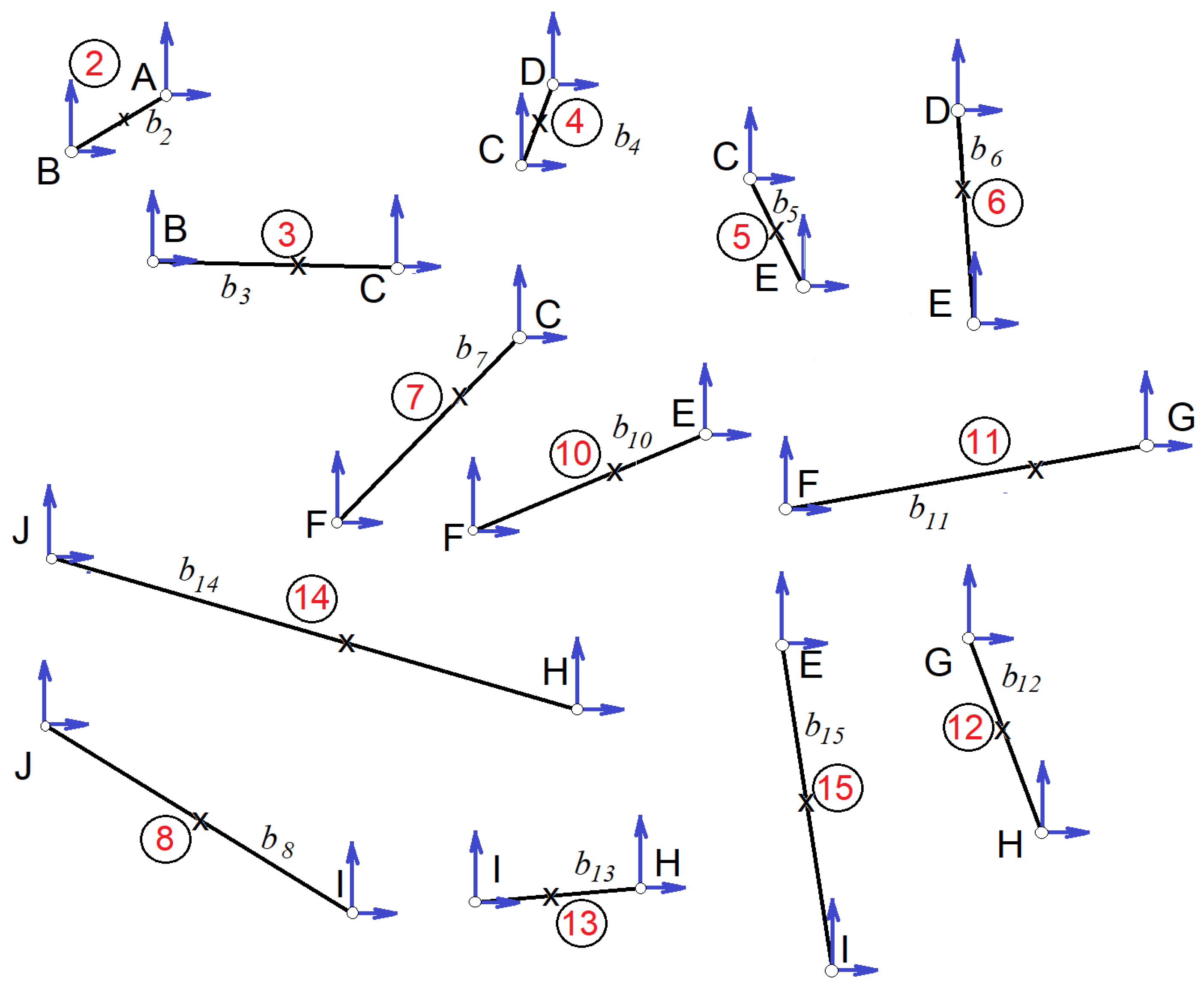
For the mechanism considered in this paper, the decomposition into component bars is presented in Figure 16.
For the considered mechanism, we have 15 considered elements. Elements 1 and 9 are fixed, so they have zero angular velocity and zero angular acceleration. The motion equations will not be written for them. For each element, the motion equations have the form of Equation (31) where k = 2, 3, 4, 5, 6, 7, 8, 10, 11, 12.
For the whole mechanism, the equations of motion are (for each bar, the equations are presented in Appendix A)
m 2 m 3 m 4 m 5 0 m 6 m 7 m 8 m 10 m 11 0 m 12 m 13 m 14 m 15 a 2 a 3 a 4 a 5 a 6 a 7 a 8 a 10 a 11 a 12 a 13 a 14 a 15 = q 2 q 3 q 4 q 5 q 6 q 7 q 8 q 10 q 11 q 12 q 13 q 14 q 15
Or, finally,
m a = Q l i a i s o n + Q e x t
where the notations are obvious.
If Equations (25) and (26) are taken into account, the acceleration vector can be expressed as a function of ε 2 and ω 2 2 . Since the system has one degree of freedom, the acceleration vector has the form
a = A 1 ε 2 + A 2 ω 2 2 .
The relationships that give the matrices A 1 and A 2 are presented in Appendix A.
When considering Equation (37) from Equation (36), we obtain
m A 1 ε 2 + A 2 ω 2 2 = Q l i a i s o n + Q e x t ,
In previous papers, the possibility of eliminating the internal liaison forces by a simple matrix multiplication (based on the fact that in the absence of friction, the mechanical work of the liaison forces is zero) was demonstrated [61,62,63]:
0 = A 1 T Q l i a i s o n .
Premultiplying Equation (38) with A 1 T results in
A 1 T m A 1 ε 2 + A 1 T m A 2 ω 2 2 = A 1 T q e x t + q l i a s o n s .
and using Equation (39), the final form of the equations is obtained:
A 1 T m A 1 ε 2 + A 1 T m A 2 ω 2 2 = A 1 T q e x t .
Or, finally,
α ε 2 + β ω 2 2 = Q e x t
where
α = A 1 T m A 1 ; β = A 1 T m A 2 ; Q e x t = A 1 T q e x t .
To study the dynamic of the system, the differential equation remains to be solved:
α d 2 α 2 d t 2 + β d α 2 d t 2 = Q e x t .

5. Conclusions

The kinematic analysis of a planar mechanism was carried out in previous papers presented in Section 1 using a graph associated with the mechanism. The original model used to determine the field of velocities and accelerations is extended to the dynamic analysis of the system. What is important is that the model used for the first step of the analysis can be used successfully in dynamic analysis. The model usually used for this step is different from the model used in the kinematic analysis. This means building two different graphs for the two stages of the analysis is needed. So, the topological structure of the mechanism is described by only one graph.
A kinematic and then a dynamic analysis of an MBS or any mechanism always requires laborious calculations to be performed, based on information that defines the structure of the system, links, geometries and constraints (the boundary conditions). In this sense, Graph Theory provides a well-established mathematical tool for the description and analysis of mechanical systems where topological structure is an important factor in their definition. The problems such a mechanism can pose are the stability of the whole system and maneuverability [54,55,56,57,58,59,60,61,62,63,64,65,66,67]. Based on an algorithm that depends on the input of geometric data, it is possible to perform a quick calculation. Thus, important decisions can be made for a system already in the design phase. The method presented in the paper offers a powerful and practical tool for the kinematic and dynamic analyses of the mechanism (in the general case of a given MBS). The utility of the method is illustrated by performing such a complex analysis for a light aircraft control mechanism.
The main advantage of the presented method is the possibility to organize the calculation and algorithmization of the study process both at the kinematic and dynamic levels of some problems involving the analysis of multibody systems. Topology allows for the definition of the structure of the mechanical system, whilst Graph Theory offers verified methods of analysis. These two stages then offer the possibility of using standard calculation programs to obtain the time response of such systems. All these new possibilities are an advantage for the designer.

Author Contributions

Conceptualization, S.V.; methodology, M.L.S., S.V. and M.M.; software, M.L.S., S.V. and M.M.; validation, S.V.; formal analysis, M.L.S. and S.V.; investigation, M.L.S., and S.V.; resources, S.V.; data curation, M.L.S. and S.V.; writing—original draft preparation, S.V.; writing—review and editing, S.V.; visualization, M.L.S. and S.V.; supervision, M.L.S. and S.V. All authors have read and agreed to the published version of the manuscript.

Funding

This research received no external funding.

Institutional Review Board Statement

Not applicable.

Informed Consent Statement

Not applicable.

Data Availability Statement

The data presented in this study are available on request from the corresponding author.

Acknowledgments

We want to thank the reviewers who have read the manuscript carefully and have proposed pertinent corrections that have led to an improvement in our manuscript.

Conflicts of Interest

The authors declare no conflicts of interest.

Appendix A

Kinematic liaisons:
a C 2 x = ε 2 b 2 y ω 2 2 b 2 x ; a B x = ε 2 L 2 y ω 2 2 L 2 x ; a C 3 x = a B x ε 3 b 3 y ω 3 2 b 3 x ; a C 2 y = ε 2 b 2 x ω 2 2 b 2 y ; a B y = ε 2 L 2 x ω 2 2 L 2 y ; a C 3 y = a B y + ε 3 b 3 x ω 3 2 b 3 y ; a C 4 x = ε 4 b 4 y ω 4 2 b 4 x ; a C x = ε 4 L 4 y ω 4 2 L 4 x ; a C 5 x = a C x ε 5 b 5 y ω 5 2 b 5 x ; a C 4 y = ε 4 b 4 x ω 4 2 b 4 y ; a C y = ε 4 L 4 x ω 4 2 L 4 y ; a C 5 y = a C y + ε 5 b 5 x ω 5 2 b 5 y ; a C 6 x = ε 6 b 6 y ω 6 2 b 6 x ; a C 14 x = ε 14 ( L 14 b 14 y ) ω 14 2 ( L 14 b 14 y ) ; a C 6 y = ε 6 b 6 x ω 6 2 b 6 y ; a C 14 y = ε 14 ( L 14 b 14 y ) ω 14 2 ( L 14 b 14 y ) ; a C 8 x = ε 8 ( L 8 b 8 y ) ω 8 2 ( L 8 b 8 y ) ; a C 13 x = ε 13 ( L 13 b 13 y ) ω 13 2 ( L 13 b 13 y ) ; a C 8 y = ε 8 ( L 8 b 8 y ) ω 8 2 ( L 8 b 8 y ) ; a C 13 y = ε 13 ( L 13 b 13 y ) ω 13 2 ( L 13 b 13 y ) ; a C 11 x = a F x ε 11 b 11 y ω 11 2 b 11 x ; a C 12 x = a G x ε 12 b 12 y ω 12 2 b 12 x ; a C 11 y = a F y + ε 11 b 11 x ω 11 2 b 11 y ; a C 12 y = a G y + ε 12 b 12 x ω 12 2 b 12 y ; a C 15 x = a E x ε 15 b 15 y ω 15 2 b 15 x ; a C 14 x = ε 14 b 14 y ω 14 2 b 14 x ; a C 15 y = a E y + ε 15 b 15 x ω 15 2 b 15 y ; a C 14 y = + ε 14 b 14 x ω 14 2 b 14 y ;
Dynamic equations:
m 2 0 0 0 m 2 0 0 0 J 2 a C 2 x a C 2 y ε 2 = X 21 + X 22 Y 21 + Y 22 X 21 b 2 sin α 2 X 22 L 2 b 2 sin α 2 Y 21 b 2 cos α 2 + Y 22 L 2 b 2 cos α 2 + 0 0 M m ;
m 3 0 0 0 m 3 0 0 0 J 3 a C 3 x a C 3 y ε 3 = X 32 + X 32 Y 33 + Y 33 X 32 b 3 sin α 3 X 33 L 3 b 3 sin α 3 Y 32 b 3 cos α 3 + Y 33 L 3 b 3 cos α 3 ;
m 4 0 0 0 m 4 0 0 0 J 4 a C 4 x a C 4 y ε 4 = X 43 + X 44 Y 43 + Y 44 X 43 b 4 sin α 4 X 44 L 4 b 4 sin α 4 Y 43 b 4 cos α 4 + Y 44 L 4 b 4 cos α 4 ;
m 5 0 0 0 m 5 0 0 0 J 5 a C 5 x a C 5 y ε 5 = X 53 + X 55 Y 53 + Y 55 X 53 b 4 sin α 5 X 55 L 5 b 5 sin α 5 Y 53 b 5 cos α 5 + Y 55 L 5 b 5 cos α 5 ;
m 6 0 0 0 m 6 0 0 0 J 6 a C 6 x a C 6 y ε 6 = X 64 + X 65 Y 64 + Y 65 X 64 b 5 sin α 6 X 65 L 6 b 6 sin α 6 Y 64 b 6 cos α 6 + Y 65 L 6 b 6 cos α 5 ;
m 7 0 0 0 m 7 0 0 0 J 7 a C 7 x a C 7 y ε 7 = X 76 + X 73 Y 76 + Y 73 X 76 L 7 b 7 sin α 7 X 73 b 7 sin α 7 Y 76 L 7 b 7 cos α 7 + Y 73 b 7 cos α 7 ;
m 8 0 0 0 m 8 0 0 0 J 8 a C 8 x a C 8 y ε 8 = X 8 , 10 + X 8 , 9 Y 8 , 10 + Y 8 , 9 X 8 , 10 L 8 b 8 sin α 8 X 8 , 9 b 8 sin α 8 Y 8 , 10 L 8 b 8 cos α 8 + Y 8 , 9 b 8 cos α 8 ;
m 10 0 0 0 m 10 0 0 0 J 10 a C 10 x a C 10 y ε 10 = X 10 , 5 + X 10 , 6 Y 10 , 5 + Y 10 , 6 X 10 , 5 L 10 b 10 sin α 10 X 10 , 6 b 10 sin α 10 Y 10 , 5 L 10 b 10 cos α 10 + Y 10 , 6 b 10 cos α 10 ;
m 11 0 0 0 m 11 0 0 0 J 11 a C 11 x a C 11 y ε 11 = X 11 , 7 + X 11 , 6 Y 11 , 7 + Y 11 , 6 X 11 , 7 L 11 b 11 sin α 11 X 11 , 6 b 11 sin α 11 Y 11 , 7 L 11 b 11 cos α 11 + Y 11 , 6 b 11 cos α 11 + 0 F a 0 ;
m 12 0 0 0 m 12 0 0 0 J 12 a C 12 x a C 12 y ε 12 = X 12 , 8 + X 12 , 7 Y 12 , 8 + Y 12 , 7 X 12 , 8 L 12 b 12 sin α 12 X 12 , 7 b 12 sin α 12 Y 12 , 8 L 12 b 12 cos α 12 + Y 12 , 7 b 12 cos α 12 ;
m 13 0 0 0 m 13 0 0 0 J 13 a C 13 x a C 13 y ε 13 = X 13 , 9 + X 13 , 8 Y 13 , 9 + Y 13 , 8 X 13 , 9 L 13 b 13 sin α 13 X 13 , 8 b 13 sin α 13 Y 13 , 9 L 13 b 13 cos α 13 + Y 13 , 8 b 13 cos α 13 ;
m 14 0 0 0 m 14 0 0 0 J 14 a C 14 x a C 14 y ε 14 = X 14 , 10 + X 14 , 8 Y 14 , 10 + Y 14 , 8 X 14 , 10 b 14 sin α 14 X 14 , 8 L 14 b 14 sin α 14 Y 14 , 10 b 14 cos α 14 + Y 14 , 8 L 14 b 14 cos α 14 ;
m 15 0 0 0 m 15 0 0 0 J 15 a C 15 x a C 15 y ε 15 = X 15 , 9 + X 15 , 5 Y 15 , 9 + Y 15 , 5 X 15 , 9 L 15 b 15 sin α 15 X 15 , 5 b 15 sin α 15 Y 15 , 9 L 15 b 15 cos α 15 + Y 15 , 5 b 15 cos α 15 ;

References

  1. Chen, W.-K. Graph Theory and Its Engineering Applications; Advanced Electrical and Computer Engineering; World Scientific Publishing Company: Singapore, 1997; ISBN 978-9810218591. [Google Scholar]
  2. Deo, N. Graph Theory with Applications to Engineering and Computer Science, 1st ed.; Dover Books on Mathematics; Dover Publications: Mineola, NY, USA, 2016; ISBN 978-0486807935. [Google Scholar]
  3. Chen, W.-K. Applied Graph Theory: Graphs and Electrical Networks, Kindle ed.; North Holland: Amsterdam, The Netherlands, 2014. [Google Scholar]
  4. Sun, L.; Zhou, Y.Z.; Chen, X.; Wu, C.Y.; Zhang, G.F. Type Synthesis and Application of Gear Linkage Transplanting Mechanisms Based on Graph Theory. Trans. ASABE 2019, 62, 515–528. [Google Scholar] [CrossRef]
  5. Santiago-Valentin, E.; Portilla-Flores, E.A.; Mezura-Montes, E.; Vega-Alvarado, E.; Calva-Yáñez, M.B.; Pedroza-Villalba, M. Graph-Theory-Based Method for Topological and Dimensional Representation of Planar Mechanisms as a Computational Tool for Engineering Design. IEEE Access 2019, 7, 587–596. [Google Scholar] [CrossRef]
  6. Escalera, J.A.; Abu-Dakka, F.J.; Abderrahim, M. Symbolic Geometric Modeling of Tree-Structure Robotic Mechanisms Using Lie Groups and Graph Theory. Asian J. Control 2018, 20, 2088–2100. [Google Scholar] [CrossRef]
  7. Cao, W.Q.; Yan, T.H. Applications of Graph Theory in Mechanism Analysis. In Emerging Topics on Differential Geometry and Graph Theory; Mathematics Research Developments; Nova Science Publishers: New York, NY, USA, 2010; pp. 1–34. [Google Scholar]
  8. Kovalev, M.D. Structural Graphs of the Theory of Mechanisms. J. Mach. Manuf. Reliab. 2023, 52, 129–133. [Google Scholar] [CrossRef]
  9. Luo, J.G.; He, M.Y. Analysis on Degree of Freedom and Singularity of Mechanism Based on Topological Graph Theory. In Proceedings of the International Conference on Frontiers of Advanced Materials and Engineering Technology (FEMET 2012), Xiamen, China, 4–5 January 2012; Parts 1–3. Volume 430–432, pp. 1943–1946. [Google Scholar]
  10. Luo, J.G.; He, M.Y. Moving capability of mechanism based on topological graph theory. In Proceedings of the 2nd Annual International Conference on Electronics, Electrical Engineering and Information Science (EEEIS-2016), Xi’an, China, 2–4 December 2016; Volume 117, pp. 518–523. [Google Scholar]
  11. Luo, J.G.; Han, J.Y. Design and Analysis of Mechanism Based on Topological Theory. In Proceedings of the International Conference on Material Science and Application (ICMSA), Suzhou, China, 13–14 June 2015; Volume 3, pp. 636–643. [Google Scholar]
  12. Liu, T.S.; Chou, C.C. Type Synthesis of Vehicle Planar Suspension Mechanism using Graph-Theory. J. Mech. Des. 1993, 115, 652–657. [Google Scholar] [CrossRef]
  13. Kawamoto, A.; Bendsoe, M.P.; Sigmund, O. Planar articulated mechanism design by graph theoretical enumeration. Struct. Multidiscip. Optim. 2004, 27, 295–299. [Google Scholar] [CrossRef]
  14. Uyguroglu, M.; Demirel, H. Kinematic analysis of tendon-driven robotic mechanisms using oriented graphs. Acta Mech. 2006, 182, 265–277. [Google Scholar] [CrossRef]
  15. Vlase, S.; Ghitescu, I.M.; Paun, M. A Kinematical Analysis of the Flap and Wing Mechanism of a Light Sport Aircraft Using Topological Models. Symmetry 2021, 13, 1243. [Google Scholar] [CrossRef]
  16. Shai, O.; Preiss, K. Graph theory representations of engineering systems and their embedded knowledge. Artif. Intell. Eng. 1999, 13, 273–281. [Google Scholar] [CrossRef]
  17. Yan, H.S.; Chiu, Y.T. An algorithm for the construction of generalized kinematic chains. Mech. Mach. Theory 2013, 62, 75–98. [Google Scholar] [CrossRef]
  18. Feng, C.M.; Liu, T.S. A graph-theory approach to designing deployable mechanism of reflector antenna. Acta Astronaut. 2013, 87, 40–47. [Google Scholar] [CrossRef]
  19. Tsai, L.W.; Chen, D.Z.; Lin, T.W. Dynamic analysis of geared robotic mechanisms using graph theory. J. Mech. Des. 1998, 120, 240–244. [Google Scholar] [CrossRef]
  20. Vucina, D.; Freudenstein, F. An Application of Graph-Theory and Nonlinear-Programming to the Kinematic Synthesis of Mechanisms. Mech. Mach. Theory 1991, 26, 553–563. [Google Scholar] [CrossRef]
  21. Shai, O. The Canonical Form of All Planar Linkage Topologies. In Proceedings of the ASME International Design. Engineering Technical Conferences/Computers and Information in Engineering Conference, San Diego, CA, USA, 30 August–2 September 2009; Parts A and B. Volume 7, pp. 1285–1294. [Google Scholar]
  22. Sedlaczek, K.; Eberhard, P. Topology Optimization of Large Motion Rigid Body Mechanisms with Nonlinear Kinematics. J. Comput. Nonlinear Dyn. 2009, 4, 021011. [Google Scholar] [CrossRef]
  23. Muller, A. Kinematic topology and constraints of multi-loop linkages. Robotica 2018, 36, 1641–1663. [Google Scholar] [CrossRef]
  24. Yan, Q.; Zhang, J.J.; Li, B.; Zhou, L. Kinematic Analysis and Dynamic Optimization Simulation of a Novel Unpowered Exoskeleton with Parallel Topology. J. Robot. 2019, 2019, 2953830. [Google Scholar] [CrossRef]
  25. Jain, A. Multibody graph transformations and analysis. Nonlinear Dyn. 2012, 67, 2779–2797. [Google Scholar] [CrossRef]
  26. Wu, Y.J.; Zhou, J.T. A hierarchical and interlamination graph self-attention mechanism-based knowledge graph reasoning architecture. Inf. Sci. 2025, 686, 121345. [Google Scholar] [CrossRef]
  27. Du, Q.L.; Fan, J.Z.; Zhao, J. Kinematic synthesis and mechanism design of a six-bar jumping leg for elastic energy storage and release based on dead points. Mech. Mach. Theory 2024, 202, 105777. [Google Scholar] [CrossRef]
  28. Che, Y.M.; Luo, W.S.; Li, Q.A. Kinematic analysis of adjusting mechanism of bamboo and wood-based special-shaped panels sucker based on graph theory and closed-loop vector method. J. Mech. Sci. Technol. 2024; early access. [Google Scholar] [CrossRef]
  29. Xia, Z.H.; Tian, C.X.; Zhang, D. The novel synthesis of origami-inspired mechanisms based on graph theory. Mech. Mach. Theory 2024, 192, 105547. [Google Scholar] [CrossRef]
  30. He, L.T.; Fang, H.R.; Zhang, D. Design of a class of reconfigurable hybrid mechanisms for large complex curved surface machining based on topological graph theory. Mech. Mach. Theory 2023, 190, 105461. [Google Scholar] [CrossRef]
  31. Nafeh, H.A.; Esmail, E.L.; Abdali, S.H. Automatic Structural Synthesis of Planetary Geared Mechanisms using Graph Theory. J. Appl. Comput. Mech. 2023, 9, 384–403. [Google Scholar]
  32. Marin, M.; Öchsner, A.; Bhatti, M.M. Some results in Moore-Gibson-Thompson thermoelasticity of dipolar bodies. ZAMM-J. Appl. Math. Mech. 2020, 100, e202000090. [Google Scholar] [CrossRef]
  33. Zhu, J.; Shi, C.; Fan, X.; Liu, R. Synthesis and Networking of Spaceborne Deployable Prismatic Antenna Mechanisms Based on Graph Theory. Int. J. Aerosp. Eng. 2024, 1–19. [Google Scholar] [CrossRef]
  34. McPhee, J.; Schmitke, C.; Redmond, S. Dynamic modelling of mechatronic multibody systems with symbolic computing and linear graph theory. Math. Comput. Model. Dyn.Syst. 2004, 10, 1–23. [Google Scholar] [CrossRef]
  35. Cui, R.J.; Guo, Z.H.; Zhu, S.S. Analysis and Design of Lower-Mobility Parallel Mechanism of Non-symmetrical Based on Variable Topology Theory. In Proceedings of the 2nd International Conference on Manufacturing Science and Engineering, Advanced Manufacturing Systems, London, UK, May 2011; Parts 1–3. Volume 201–203, pp. 1907–1913. [Google Scholar]
  36. Shieh, W.B.; Sun, F.; Chen, D.Z. On the Topological Representation and Compatibility of Variable Topology Mechanisms. In Proceedings of the ASME International Design Engineering Technical Conferences/Computers and Information in Engineering Conference, Montreal, QC, Canada, 15–18 August 2010; Parts A and B. Volume 7, pp. 1223–1230. [Google Scholar]
  37. Lu, Y.; Ye, N.J. Type synthesis of parallel mechanisms by utilizing sub-mechanisms and digital topological graphs. Mech. Mach. Theory 2017, 109, 39–50. [Google Scholar] [CrossRef]
  38. Guo, Z.H.; Wang, K.J.; Qi, H.L. Topological Design and Genetic Synthesis of the Variable Topology Parallel Mechanisms. In Proceedings of the International Conference on Reconfigurable Mechanisms and Robots, London, UK, 22–24 June 2009; pp. 197–204. [Google Scholar]
  39. Zhang, W.J.; Breteler, A.J.K. An approach to mechanism topology identification with consideration of design processes progression. Proc. Inst. Mech. Eng. Part C-J. Mech. Eng. Sci. 1997, 211, 175–183. [Google Scholar] [CrossRef]
  40. Negrean, I.; Crisan, A.V.; Vlase, S. A New Approach in Analytical Dynamics of Mechanical Systems. Symmetry 2020, 12, 95. [Google Scholar] [CrossRef]
  41. Yu, J.; Han, S.M.; Kim, Y.Y. Simultaneous Shape and Topology Optimization of Planar Linkage Mechanisms Based on the Spring-Connected Rigid Block Model. J. Mech. Des. 2020, 142, 011401. [Google Scholar] [CrossRef]
  42. Lu, Y.; Leinonen, T. Type synthesis of unified planar-spatial mechanisms by systematic linkage and topology matrix-graph technique. Mech. Mach. Theory 2005, 40, 1145–1163. [Google Scholar] [CrossRef]
  43. Zhan, J.Q.; Yan, J.K.; Liu, M. Optimal design of electro-thermo-mechanical microactuators considering minimum length scale constraints. Proc. Inst. Mech. Eng. Part C-J. Mech. Eng. Sci. 2024; early access. [Google Scholar] [CrossRef]
  44. Jia, Z.Y.; You, J.H.; Han, Z. Cooperative Cognitive Dynamic System in UAV Swarms: Reconfigurable Mechanism and Framework. IEEE Veh. Technol. Mag. 2024; early access. [Google Scholar] [CrossRef]
  45. Jiang, W.; Chen, X.D.; Hu, H.P. Vibration Calculation of Spatial Multibody Systems Based on Constraint-Topology Transformation. J. Mech. 2011, 27, 479–491. [Google Scholar] [CrossRef]
  46. Müller, A. Screw and Lie group theory in multibody kinematics. Motion representation and recursive kinematics of tree-topology systems. Multibody Syst. Dyn. 2018, 43, 37–70. [Google Scholar] [CrossRef]
  47. Vlase, S.; Marin, M.; Scutaru, M.L.; Munteanu, R. Coupled transverse and torsional vibrations in a mechanical system with two identical beams. AIP Adv. 2017, 7, 065301. [Google Scholar] [CrossRef]
  48. Codarcea-Munteanu, L.; Marin, M.; Vlase, S. The study of vibrations in the context of porous micropolar media thermoelasticity and the absence of energy dissipation. J. Comput. Appl. Mech. 2023, 54, 437–454. [Google Scholar] [CrossRef]
  49. Vlase, S.; Teodorescu, P.P.; Itu, C.; Scutaru, M.L. Double Cardan Joint. Rom. J. Phys. 2013, 58, 882–892. [Google Scholar]
  50. Zhao, Q.; Wu, H.T.; Zhou, M.H. Generalized Mass Metric and Recursive Momentum Formulation for Dynamics of Multibody Systems. In Proceedings of the ASME International Design Engineering Technical Conferences/Computers and Information in Engineering Conference, Montreal, QC, Canada, 15–18 August 2010; Parts A–C. Volume 4, pp. 505–515. [Google Scholar]
  51. Tromme, E.; Sonneville, V.; Duysinx, P. On the equivalent static load method for flexible multibody systems described with a nonlinear finite element formalism. Int. J. Numer. Methods Eng. 2016, 108, 646–664. [Google Scholar] [CrossRef]
  52. Vlase, S.; Itu, C.; Marin, M.; Luminta Scutaru, M.; Sabou, F.; Necula, R. Vibration analysis of the Gamma-Ray element in the ELI-NP interaction chamber (IC). J. Comput. Appl. Mech. 2024, 55, 275–288. [Google Scholar] [CrossRef]
  53. Thulasiraman, K. Graphs: Theory and Algorithms; Wiley-Interscience: Hoboken, NJ, USA, 1992. [Google Scholar]
  54. EASA. Certification Specification and Acceptable Means of Compliance for Light Sport Aeroplanes, CS-LSA; European Aviation Safety Agency: Cologne, Germany, 2013. [Google Scholar]
  55. Gudmundsson, S. General Aviation Aircraft Design—Methods and Procedures, 1st ed.; Elsevier Inc.: Oxford, UK, 2014. [Google Scholar]
  56. Roskam, J. Airplane Design, Part I. Preliminary Sizing of Airplanes; University of Kansas: Lawrence, KS, USA, 1985. [Google Scholar]
  57. Zipfel, P.H. Modeling and Simulation of Aerospace Vehicle Dynamics, Revised Edition; AIAA: Las Vegas, NV, USA, 2014. [Google Scholar]
  58. Kroes, M.J.; Rardon, J.R.; Nolan, M.S. Aircraft Basic Science, 8th ed.; Mac Graw Hill: New York, NY, USA, 2013. [Google Scholar]
  59. Abzug, M.J. Airplane Stability and Control, 2nd ed.; Cambridge University Press: Cambridge, UK, 2008. [Google Scholar]
  60. Stanciu, M.D.; Vlase, S.; Marin, M. Vibration Analysis of a Guitar considered as a Symmetrical Mechanical System. Symmetry 2019, 11, 727. [Google Scholar] [CrossRef]
  61. Scutaru, M.L.; Vlase, S.; Marin, M.; Modrea, A. New analytical method based on dynamic response of planar mechanical elastic systems. Bound. Value Probl. 2020, 2020, 104. [Google Scholar] [CrossRef]
  62. Marin, M.; Chirila, A.; Ochsner, A.; Vlase, S. About finite energy solutions in thermoelasticity of micropolar bodies with voids. Bound. Value Probl. 2019, 2019, 89. [Google Scholar] [CrossRef]
  63. Vlase, S.; Negrean, I.; Marin, M.; Scutaru, M.L. Energy of Accelerations Used to Obtain the Motion Equations of a Three- Dimensional Finite Element. Symmetry 2020, 12, 321. [Google Scholar] [CrossRef]
  64. Zhou, C.; Zhang, R.; Wang, C. Flap-control mechanism for flapping-wing micro air vehicles. Proc. Inst. Mech. Eng. Part G-J. Aerosp. Eng. 2019, 233, 1537–1545. [Google Scholar] [CrossRef]
  65. Isbitirici, A.; Altug, E. Design and Control of a Mini Aerial Vehicle that has Four Flapping-Wings. J. Intell. Robot. Syst. 2017, 88, 247–265. [Google Scholar] [CrossRef]
  66. Huang, Y.; Nitsche, M.; Kanso, E. Stability versus maneuverability in hovering flight. Phys. Fluids 2015, 27, 061706. [Google Scholar] [CrossRef]
  67. Li, W.; He, G.Y.; Shi, J. The Design and Research Based on Spatial Crank-rocker Mechanism of Flapping Micro Air Vehicle. In Proceedings of the International Conference on Mechanical Science and Mechanical Design, MSMD 2015, Changsha, China, 12–13 December 2015; pp. 182–187. [Google Scholar]
Figure 1. A polygon is replaced with triangles.
Applsci 14 08531 g001
Figure 2. A lever with multiple joints is replaced with triangles.
Applsci 14 08531 g002
Figure 3. A straight lever with multiple joints is replaced with triangles.
Applsci 14 08531 g003
Figure 4. (a) Planar four-bar mechanism; (b) vector contour; (c) associated graph; and (d) the tree of the associated graph.
Applsci 14 08531 g004
Figure 5. A sketch of the mechanism.
Applsci 14 08531 g005
Figure 6. Three vector contours of the mechanism.
Applsci 14 08531 g006
Figure 7. (a) Associated graph. (b) A tree of the graph.
Applsci 14 08531 g007
Figure 8. (a) Sketch of the mechanism. (b) Sketch of the equivalent mechanism.
Applsci 14 08531 g008
Figure 9. The vector contour and independent loops of the mechanism.
Applsci 14 08531 g009
Figure 10. Kinematical sketches. (a) real mechanism; (b) associated mechanism.
Applsci 14 08531 g010
Figure 11. Equivalent bars mechanism.
Applsci 14 08531 g011
Figure 12. The graph attached to the mechanism.
Applsci 14 08531 g012
Figure 13. A tree of the graph.
Applsci 14 08531 g013
Figure 14. The command mechanism.
Applsci 14 08531 g014
Figure 15. A free body diagram for an element k defined by the nodes i and j.
Applsci 14 08531 g015
Figure 16. Free body diagrams for the elements of the mechanism.
Applsci 14 08531 g016
Disclaimer/Publisher’s Note: The statements, opinions and data contained in all publications are solely those of the individual author(s) and contributor(s) and not of MDPI and/or the editor(s). MDPI and/or the editor(s) disclaim responsibility for any injury to people or property resulting from any ideas, methods, instructions or products referred to in the content.