Article

Development of an Inertial Linear Ultrasonic Motor with a Double-Stator Structure Based on Bending Mode

1
State Key Laboratory of Mechanics and Control for Aerospace Structures, Nanjing University of Aeronautics and Astronautics, Nanjing 210016, China
2
NUAA Super Control Technology Co., Ltd., Nanjing 210016, China
*
Author to whom correspondence should be addressed.
Appl. Sci. 2024, 14(18), 8533; https://doi.org/10.3390/app14188533
Submission received: 31 August 2024 / Revised: 11 September 2024 / Accepted: 19 September 2024 / Published: 22 September 2024

Abstract

:
An inertial linear ultrasonic motor with a novel double-stator structure is proposed for achieving higher performance and resolution in this paper. Utilizing a symmetrical structure and single sawtooth wave signal, the prototype is capable of outputting effective linear motion based on inertial movement. The validity and rationality of the prototype are investigated by conducting finite element analyses. The experimental setups are built up to acquire the output characteristics of the motor. The experimental results indicate that the motor can achieve a maximum output velocity of 8.746 mm/s and thrust force of 1.645 N, which is almost twice the output performance of a motor with a single stator. The displacement solution of the motor can be adjusted by changing the amplitude of the voltage, with a resolution of 27 nm. Simultaneously, the relationships between the output characteristics and the input parameters are measured and analyzed during the experiments. Compared to the actuators with complex structures and multi-signal drives, the proposed motor exhibits the merits of higher output performance with the double-stator structure, providing an alternative direction for the further development of the inertial linear ultrasonic motor.

1. Introduction

The field of precision motion control has witnessed a significant advancement with the development of inertial linear piezoelectric actuators (ILPAs), proposed in the 1980s, leveraging the inverse piezoelectric effect to convert electrical energy to mechanical displacement and working based on the vibration motion against frictional interaction. Due to their high resolution, fast response, and compact structure, they have been widely used in various applications such as camera modules [1,2,3], micro-robotics [4,5], biomedical [6,7] aerospace, etc. [8,9,10]. Based on their operating frequency, ILPAs can be categorized into non-resonant-type inertial linear piezoelectric actuators and inertial linear ultrasonic motors (ILUMs) [11].
Utilizing the deformation generated by the lead zirconate titanate piezoelectric ceramic (PZT) stacks under adjustable voltage and frequency, non-resonant-type ILPAs are capable of outputting displacement. However, the output performance of these actuators has been shown to be limited by the deformation of the PZT stacks, so some non-resonant-type ILPAs are usually proposed with an integrated structure [12,13,14] and configurations that are used for amplifying displacement in addition to the necessary clamping structures [15,16]. In addition, their large thrust force and high velocity cause difficulty in actualization as a result of their low driving frequency [17].
ILUMs exhibit the merits of higher positioning accuracy and displacement resolution on account of their high driving frequency [18], small stepping pitch [19,20], and various exciting signals [21]. Compared to non-resonant-type ILPAs, the output performance of ILUMs is improved significantly since they are driven at a resonant frequency under high voltage, and therefore more complicated driving methods [21] and strict driving frequency control feeding methods are required to avoid operation failures. As for research on the driving mechanisms, signal, friction, and structure are common design methods [11]. However, the complexity of the control method is not conducive to the overall integration of ILUMs, so it is necessary to arrange the structure of the motor while retaining the characteristics of the resonant driving method. Several types of ILUMs operating based on the resonant mode have been proposed. However, from a structural perspective, the direct exposure of the edges of PZTs in motors presents a significant design shortcoming that makes the structure fragile [17]. Furthermore, the elastomer to which the PZTs are bonded lacks the necessary constraints, resulting in an unstable and unreliable structure [1,2]. This not only leads to the activation of undesired excitation modes but also significantly degrades the output performance. Meanwhile, the improper arrangement of PZTs and an unstable structure can complicate and hinder the processing and assembly procedures from an engineering application standpoint. Therefore, these drawbacks suggest a need for structural innovation and design improvements to enhance ILUMs’ stability, reliability, and performance.
In this paper, an inertial linear ultrasonic motor with a double-stator structure (ILUM-D) was proposed based on the bending mode, focusing on the process of designing and analyzing a novel structure that leads to higher performance and requires only a single signal for an effective output. The double-stator structure improves the output performance of the motor while allowing for easy installation and a wide range of engineering applications. A finite element model of the prototype has been proposed to obtain the mechanical characteristics for further structure optimization, demonstrating the performance advantages of the ILUM-D over an inertial linear ultrasonic motor with a single-stator structure (ILUM-S). Several experiments were conducted to verify the feasibility and property of the prototype. In the meantime, the experimental results were also compared with those of the analytical modeling and the finite element analyses. The effect of the double-stator structure on motor output performance enhancement is thoroughly verified.
This work is organized as follows: In Section 2, the configuration and the working mechanism of the ILUM-D are introduced. In Section 3, a finite element model of the ILUM-D is proposed for modal analyses and transient analyses. Section 4 presents the experimental results of the prototype, which are compared with the simulation results. The conclusions are presented in Section 5.

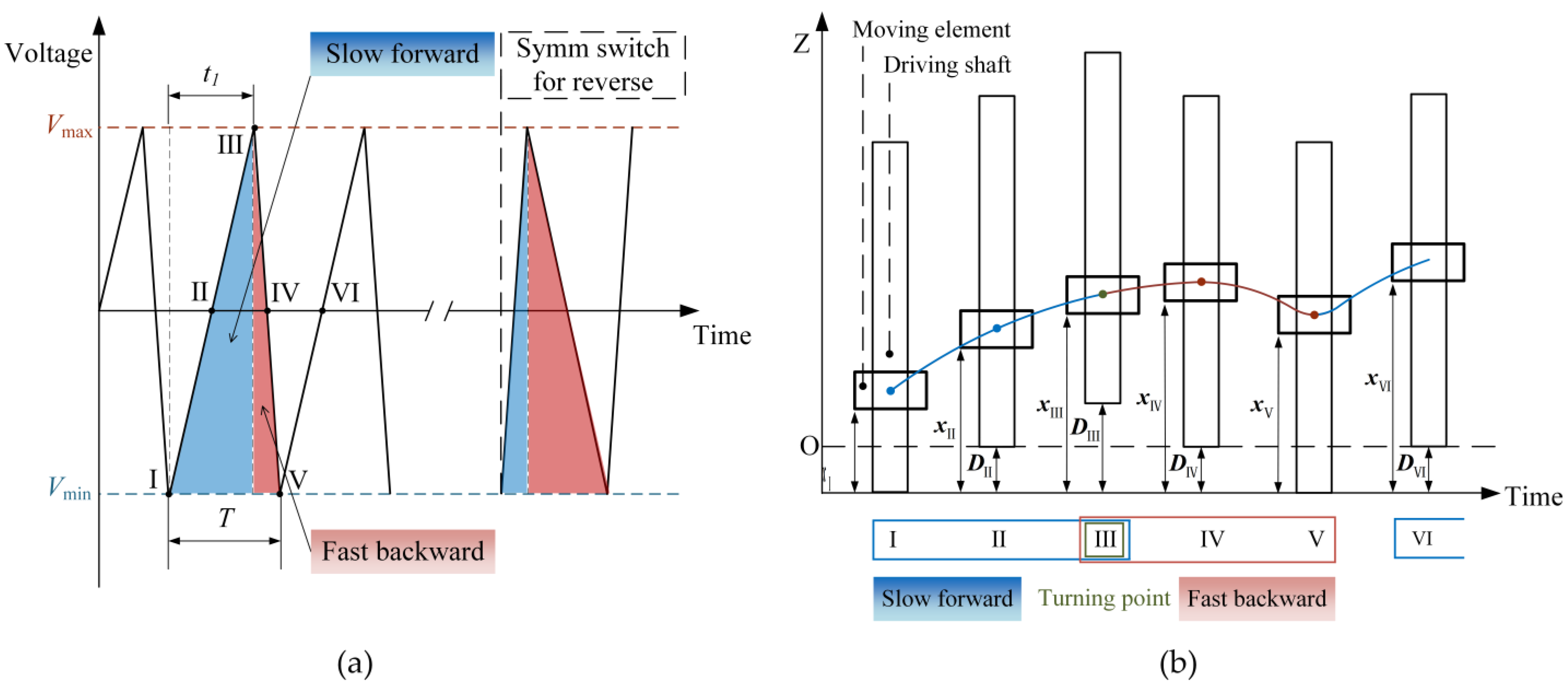
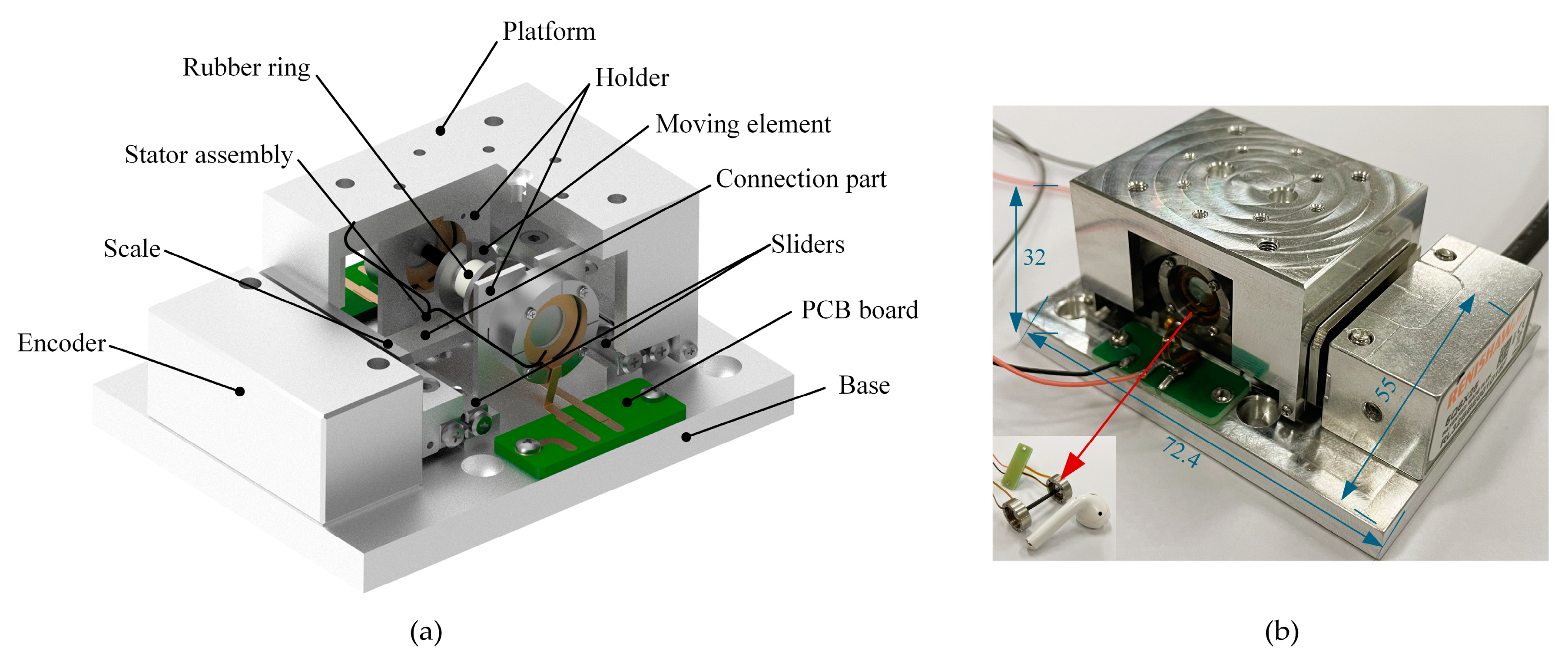
2. Configuration and Working Mechanism

The proposed ILUM-D consists of four PZTs and electrodes, two stators with the same structure, a driving shaft, and the moving element, as illustrated in Figure 1b. The ring-shaped PZTs are attached to the inner and outer surfaces of the stators with identical polarization directions. The utilization of ring-shaped PZTs avoids a maximum strain region in the stator, which prevents the PZTs from fragmenting at high voltages. On account of the technical requirements of the vibration mode and the installation process, the stator is divided into the excite region, isolation region, and constrain region, as shown in Figure 1a. The symmetrical structure of the motor allows for easy installation and commissioning, which ensures that the driving shaft is positioned horizontally and vertically on the stator surface. The cylindrical driving shaft is fixed between the stators and transfers the axial displacement generated by the stators to the moving element; hence, the resonant frequency of the driving shaft should be verified to avoid the proposed ILUM-D working frequency.
Generally, inertial movement is achieved by applying sawtooth wave signal voltage to the PZTs. The proposed stators are excited by the PZTs in an external bending vibration mode as shown in Figure 1c, while the driving shaft works in an up–down motion. The moving element is pressed into the driving shaft with a rubber band. To generate an axial displacement of each stator, only one driving signal source is necessary, as shown in Figure 1d.
First of all, the sawtooth wave signal symmetry is used to illustrate the proportion (t1/T) of rising time in a cycle as shown in Figure 2a. The sawtooth wave signals adopted in this paper are 100% or 0% symmetry, which means that the rising time (falling time) of the signal occupies an entire period, and the difference between them only determines the motion direction. The schematic of the motion principle is demonstrated under a sawtooth wave signal with a symmetry of 100%; the ILUM-D working period can be divided into slow forward, turning point, and fast backward based on the applied sawtooth signal. Precisely speaking, the asymmetric motion is reflected significantly on the driving shaft and the motion between the moving element and the driving shaft is almost slip-type, since the proposed ILUM-D works under a sawtooth signal with resonant frequency. As shown in Figure 2b, in the slow forward period, the position of the moving element can be described with the distance xI at the moment I. During sections I-II-III, the applied voltage rises slowly and the value of the acceleration of the driving shaft also rises slowly, while the position of the moving element is xII to xIII and the position of the driving shaft is DII to DIII. After the turning point III, the applied voltage drops sharply during sections III-IV-V. In the fast backward period, the driving shaft moves back to the DIV position while the moving element is still moving forward and keeps the xIV position as a result of its inertia; then, the moving element will keep moving until reaching the xV position, which leads to backward motion │xVxIV│. In this way, the relative movement between the moving element and the driving shaft is generated with the value of │xVxI│, and the motion direction of the moving element can be changed by applying a sawtooth wave signal with 0% symmetry.

3. Simulation and Analyses

3.1. Modal Analyses

First of all, the feasibility of the stator needs to be verified by using the commercial software ANSYS R18.0 to acquire the stator and assembly modal analyses results. It should be noted here that the modal analyses in this paper were conducted under free boundary conditions and the stators and the driving shaft were bonded. The material properties of the ILUM-D are listed in Table 1.
The PZTs used in the proposed motor were four PZT-8 ceramic rings with an inner diameter of 6 mm, outer diameter of 10 mm, and thickness of 0.5 mm. The PZT-8 rings were used due to their higher mechanical quality and better stability at high drive levels [22]. For the PZT-8 ceramic rings used in this paper, a signal with high voltage amplitude was applied in order to achieve full performance. The density of each PZT-8 was 7500 kg/m3. Their piezoelectric matrix, stiffness matrix, and dielectric matrix are as follows [23]:
[ e ] = 0 0 7.209 0 0 7.209 0 0 15.118 0 0 0 12.332 0 0 0 12.332 0   N / V · m
[ C E ] = 1.206 0 0 0 0 0 0.535 1.206 0 0 0 0 0.515 0.515 1.045 0 0 0 0 0 0 0.313 0 0 0 0 0 0 0.313 0 0 0 0 0 0 0.346 × 10 11   N / m 2
[ ε T ] = 1.53 1.53 1.50 × 10 8   F / m
Table 1. Material properties of the ILUM-D.
ComponentMaterialsDensity (kg/m3)Young’s Modulus (N/m2)Poisson’s Ratio
StatorStructural Steel78502.0 × 10110.3
Moving elementStainless Steel77602.1 × 10110.28
Driving shaftCarbon Fiber1800E1 = 1.6 × 10¹¹ν12 = 0.33
E1 = 9.7 × 10⁹ν23 = 0.28
E1 = 9.7 × 10⁹ν13 = 0.33
To determine the resonance frequency of the stator assembly, a finite element model was built and subsequent simulations were carried out. The feasibility of the stator was verified by acquiring the working vibration mode through the modal analyses shown in Figure 3. The isolation region and constrain region of the stator were not involved during the vibration, as shown in Figure 3a. The resonance frequency of the stator was calculated as 44.111 kHz. The modal analyses of the stator assembly, which consists of stator(s) and the driving shaft, were also conducted, as shown in Figure 3b,c. In particular, there was no stress or strain within the driving shaft, which merely transmits the stator vibrations during the operation process. The resonance frequencies of the single stator assembly (SA) and the double-stator assembly (DA) were calculated as 33.052 kHz and 36.049 kHz.
The modal analyses results indicate that the addition of the driving shaft decreases the bending mode frequency of the SA, potentially because of the extra mass added to the stator. However, the bending mode frequency of the DA is higher than that of the SA, which could be due to the changed overall boundary conditions, especially for the driving shaft.
Figure 3. Modal analyses results in ANSYS: (a) stator, 44111 Hz; (b) SA, 33052 Hz; (c) DA, 36049 Hz.
Applsci 14 08533 g003

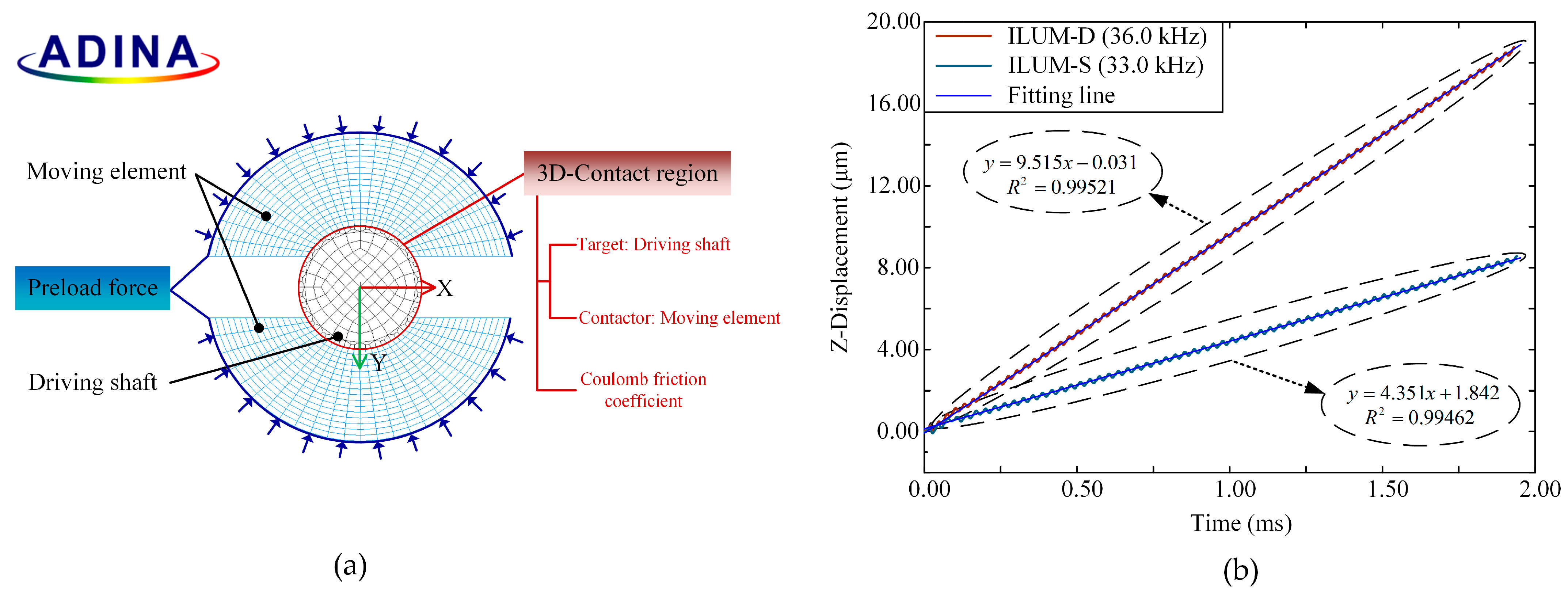
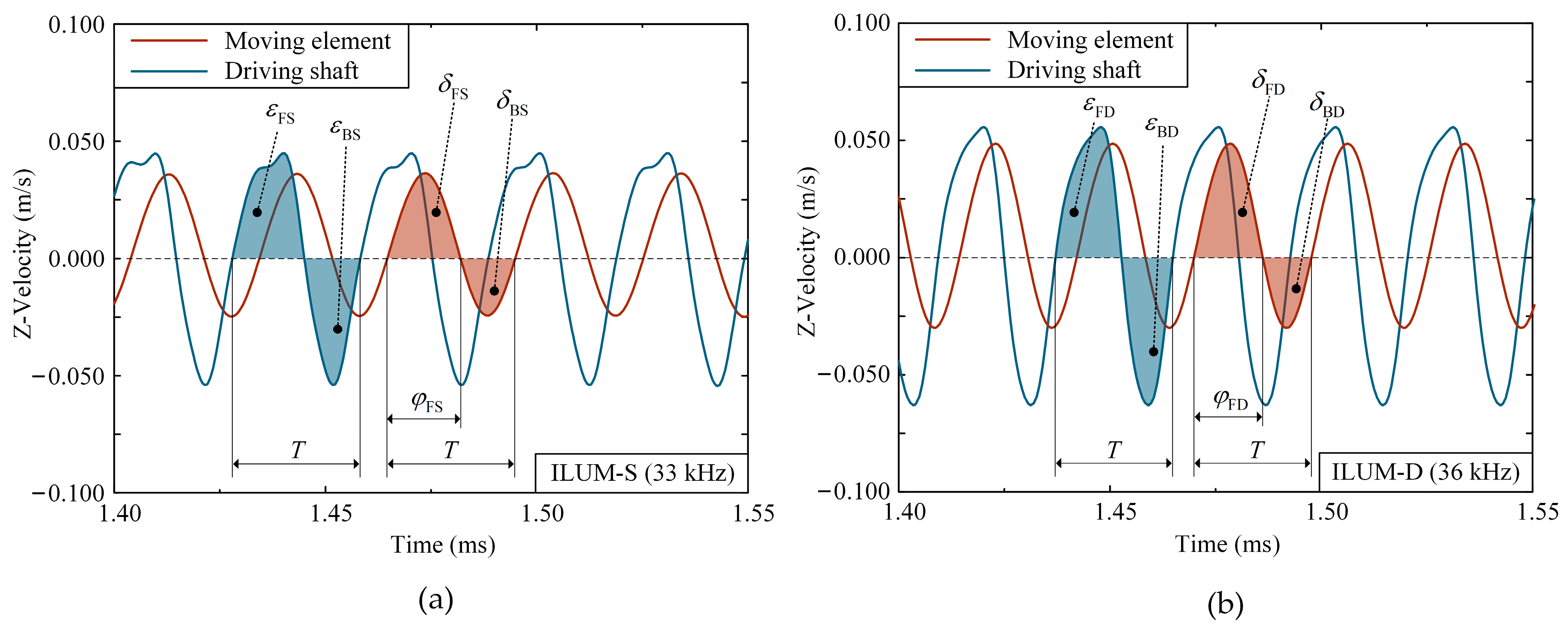
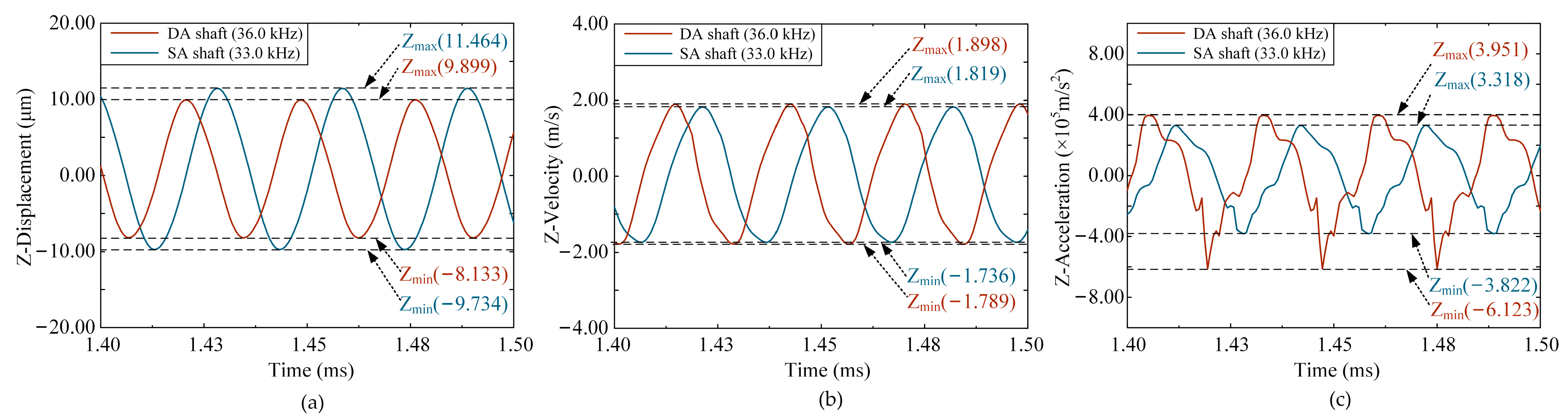
3.2. Transient Analyses

For further acquisition of the stator assembly vibration characteristics, dynamic simulations were conducted in ADINA based on the results of the modal analyses. It should be noted here that the transient analyses in this paper were conducted under fixed boundary conditions. The parameters of the voltage signal applied to the SA were set as 33 kHz and 500 Vp-p, and the parameters of the voltage signal applied to the DA were set as 36 kHz and 500 Vp-p. The Z-displacement and Z-acceleration of the driving shaft under the sawtooth wave signal with 500 Vp-p applied voltage were obtained. As shown in Figure 4, a significant divergence exists between the minimum and maximum vibration amplitudes of the driving shaft due to an asymmetrical excite signal. Though the motion range of the DA shaft is narrower than the SA shaft, as shown in Figure 4a, the velocity and acceleration range of the DA shaft is wider than the SA shaft, which indicates that the double-stator structure is capable of higher carrying abilities, as shown in Figure 4b,c.
Based on the results of the stator assembly dynamic simulations, the preload force can be set properly based on Newton’s second law. Since the motor is functional on account of normal inertial motion, the contact model of the motor is proposed as shown in Figure 5a. The contact model consists of the driving shaft and moving element, and the whole model aims to verify the feasibility of the motor structure as well as to obtain usable transient results. The transient response of the moving element displacement in the axial direction under the sawtooth wave signal with 500 Vp-p applied voltage is shown in Figure 5b, and R2 indicates the degree of fit of the fitting line to the original displacement curve; the closer to 1, the more representative of the original displacement data. It can be calculated that the output velocity of the ILUM-S under a 33 kHz excitation frequency is 4.351 mm/s and that of the ILUM-D under 36 kHz is 9.515 mm/s. The velocity curves of the moving element and the driving shaft were also obtained as shown in Figure 6. First of all, it is clear that there is almost no relative stationary motion between the moving element and the driving shaft during both motor operations. The velocity of the driving shaft is significantly decreased compared to that in Figure 4b as a consequence of friction. The forward displacement and the backward displacement of the moving element/driving shaft are expressed as δ F , δ B and ε F , ε B , as shown in Figure 6. The velocity integration results of δ F , δ B are obtained using MATLAB R2018a, as shown in Table 2, and ε F + ε B = 0 , since the motion of the driving shaft is reciprocating during one operation period. Combined with the data in Table 2, it can be found that the δ F of the ILUM-D expressed as δ F D is larger than that of the ILUM-S expressed as δ F S , while the δ B of the ILUM-D expressed as δ B D is smaller than that of the ILUM-S expressed as δ B S , resulting in a larger effective step displacement in one operation period expressed as δ , as shown in Table 2. Furthermore, the proportion of the forward phases in one operation period is also calculated and expressed as φ F / T , as shown in Table 2, indicating there is a slight distinction between the motor’s forward proportions. Due to the higher resonance frequency and symmetrical structure of the ILUM-D, the asymmetrical vibration is more significant under the same excitation conditions, which leads to higher output velocity.
Table 2. Data calculated in MATLAB.
DataILUM-SILUM-D
δ F (μm)0.336230.40420
δ B (μm)−0.19448−0.14609
δ (μm)0.141750.25811
φ F / T 0.576120.58158
Figure 5. Transient analyses results of the prototype: (a) contact model of the ILUM in ADINA; (b) output displacement of the moving element under the 500 Vp-p sawtooth wave voltage.
Applsci 14 08533 g005
It is worth mentioning here that the comparison of the output parameters between the ILUM-S and the ILUM-D in the simulation analyses was performed to provide data support for the subsequent experimental measurements to facilitate a more comprehensive comparison of the output performance of the motors. Furthermore, the simulation results indicate that the output performance of the motor, e.g., the velocity at a fixed preload force, can be determined from the results of the stator assembly transient analyses.
Figure 6. Transient response results of the velocity of the moving element and the driving shaft under the 500 Vp-p sawtooth wave voltage: (a) ILUM-S; (b) ILUM-D.
Applsci 14 08533 g006

4. Experimental Results

For experimental measurements, the experimental platform was designed as shown in Figure 7a, consisting of the stator assembly, moving element, rubber ring, scale encoder, holder, and the transmission and circuit components. The prototype with the transmission platform was fabricated as shown in Figure 7b while vibration and mechanical characteristic measurements were conducted to verify the finite element analyses results. Figure 8a and Figure 9a show the experimental system. The applied signal was supplied by a digital function generator (AFG 3022B; Tektronix Inc., Beaverton, OR, USA) and amplified by power amplifiers (HFVA-64; Foneng Technology Co., Ltd., Shenzhen, China).

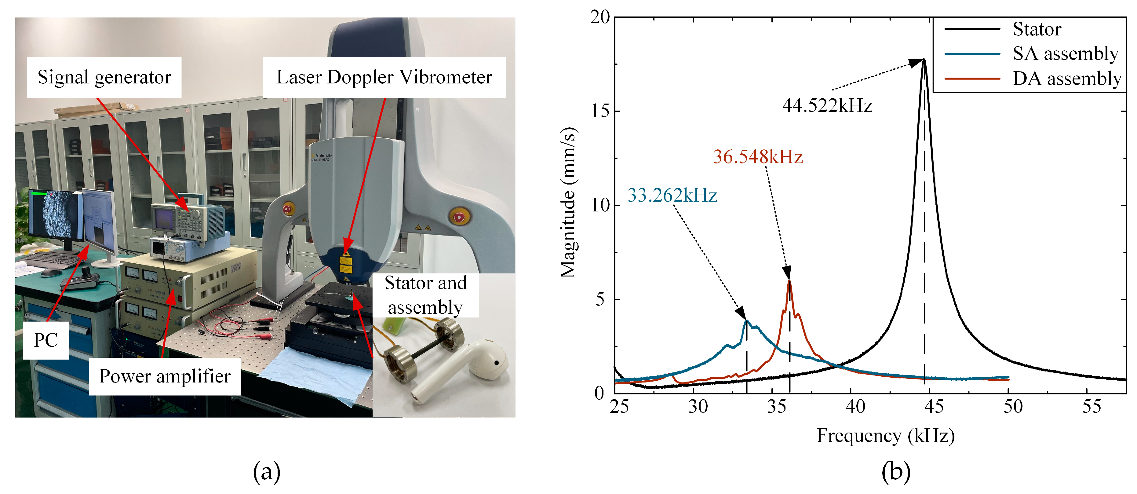
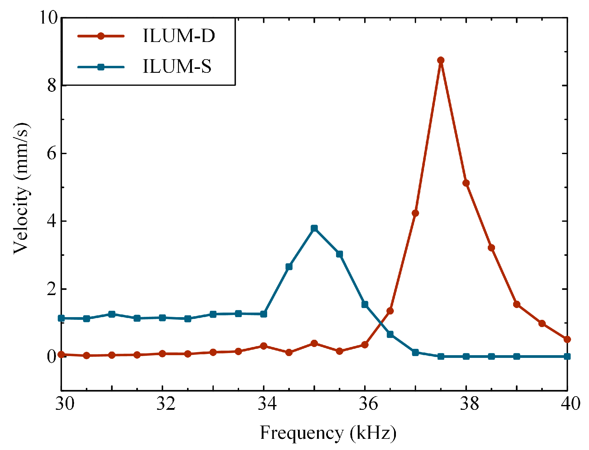
4.1. Vibration Characteristics Measurement

First of all, each resonant frequency of the stator, the SA, and the DA were measured by a laser Doppler vibrometer (MSA-100-3D; Polytec Ltd., Waldbronn, Germany) [24] as shown in Figure 8b at 44.522 kHz, 33.262 kHz, and 36.548 kHz under sinusoidal signals, while the amplitude of the applied voltage was 80 Vp-p. It should be pointed out that the measured resonant frequency results are slightly different from the simulation results due to manufacturing errors.
Figure 8. Vibration characteristic measurement: (a) Experimental system for vibration characteristics measurement; (b) frequency domain corresponding curve of the stator, SA, and DA under the 80 Vp-p sinusoidal wave voltage.
Applsci 14 08533 g008

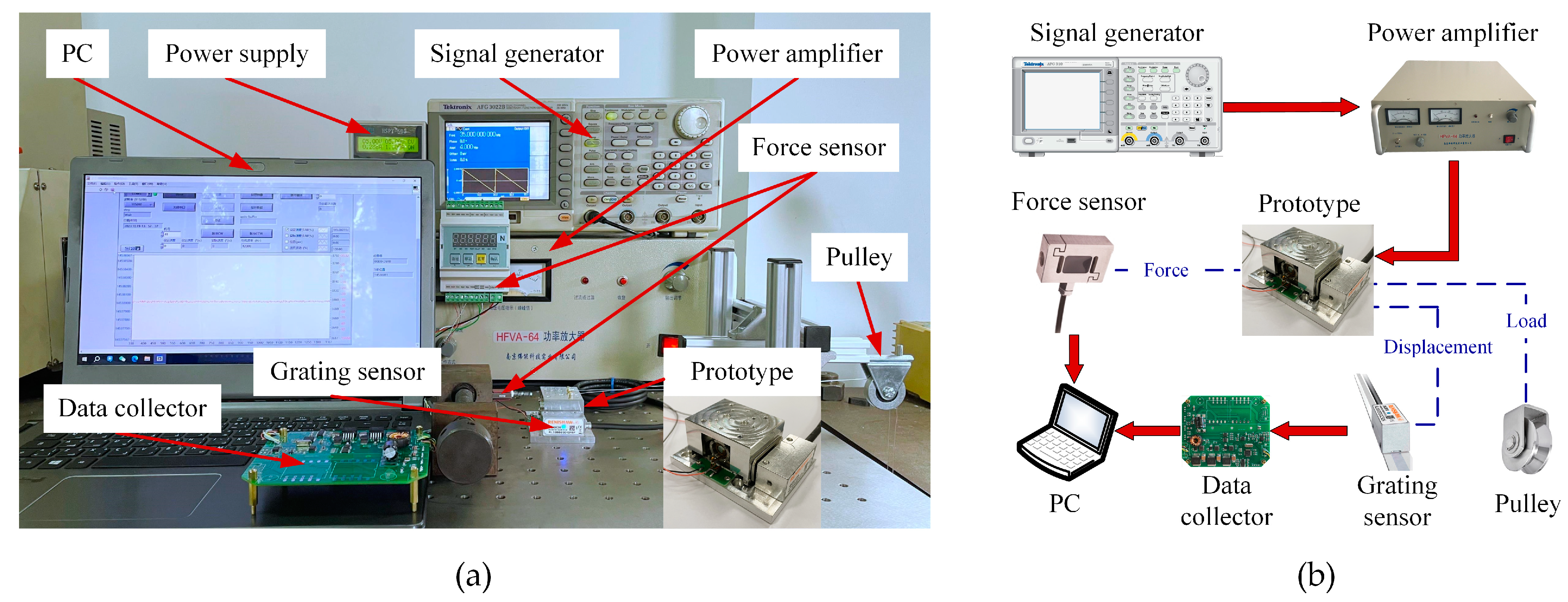
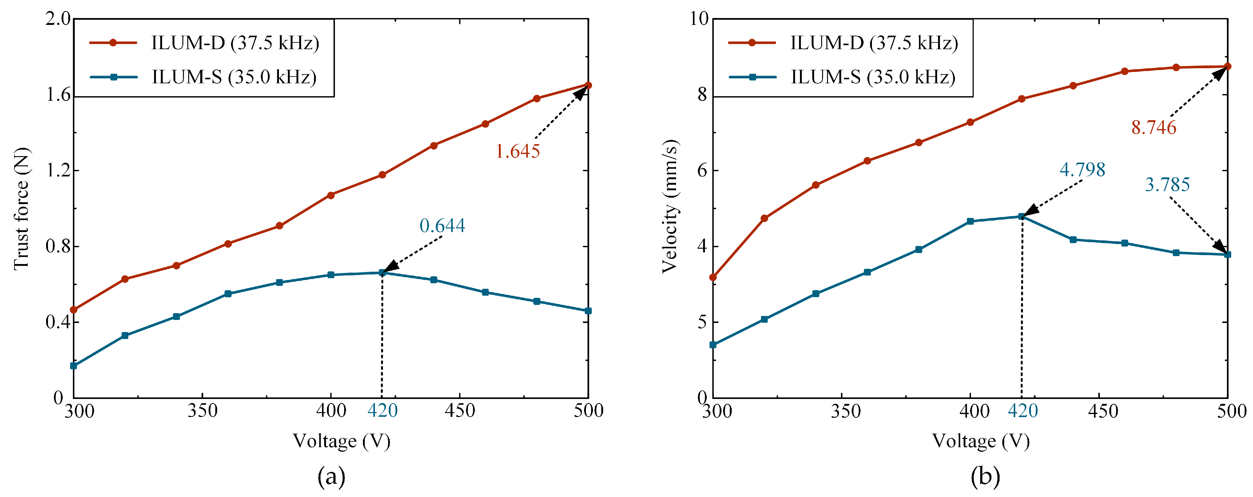
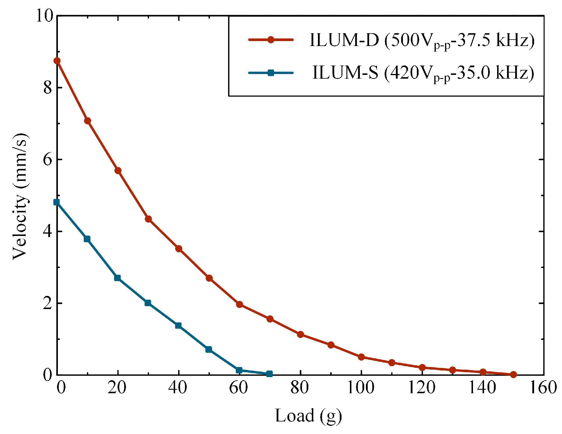
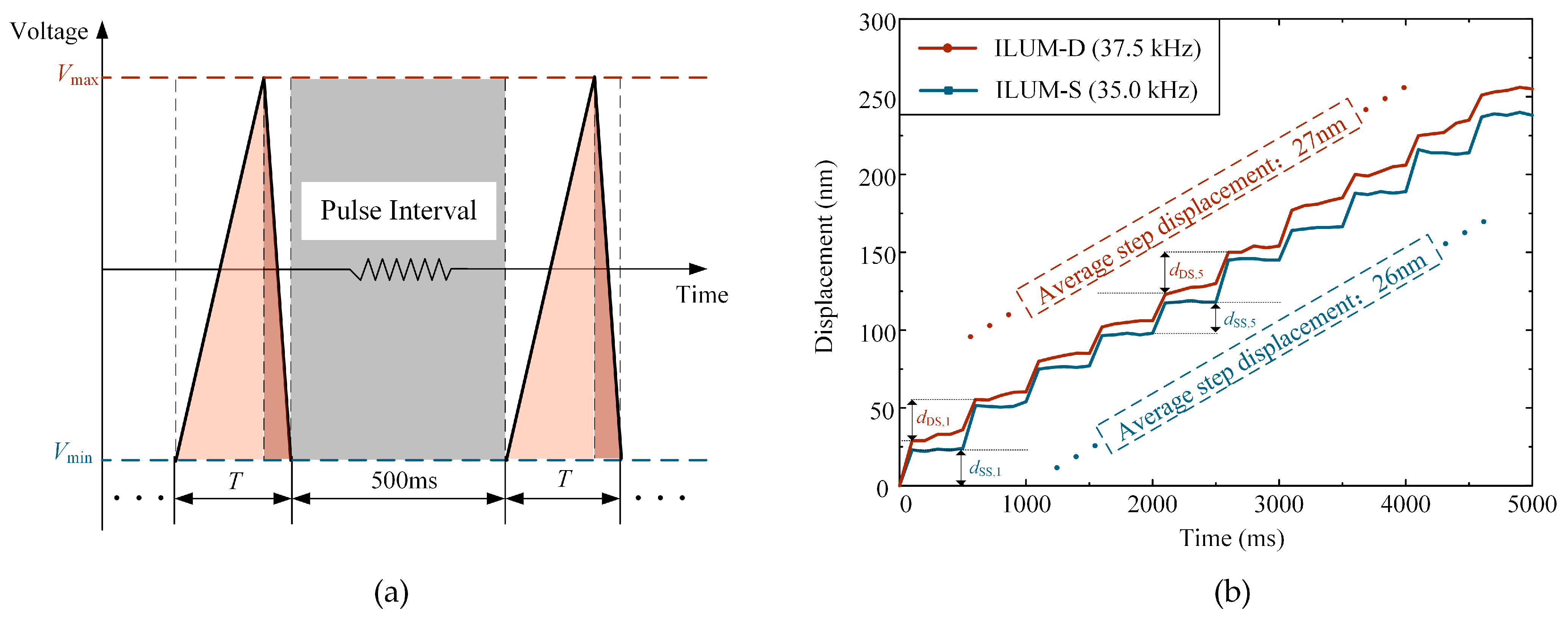
4.2. Mechanical Characteristics Measurement

Next, the displacement and velocity of the prototype were measured by a grating sensor (RL32BBE001D15F; Renishaw Plc., Gloucestershire, UK) with a resolution of 1 nm [25], which was effective for acquiring the displacement changes in the prototype. A data collector was designed to visualize the grating sensor data with the PC software based on LabVIEW. The maximum thrust force of the prototype was measured by a force sensor (LH-S09A3-5N; Liheng Sensor Technology Co., Ltd., Shanghai, China) using a spring as a cushion; the load characteristic of the prototype was measured by a fixed pulley and weights which supplied a stable load parallel to the direction of the prototype’s movement, as shown in Figure 9b.
Figure 9. Experimental system for measuring mechanical characteristics: (a) setup and prototype; (b) schematic diagram of the experimental system.
Applsci 14 08533 g009
To obtain the optimal driving frequency, the output velocity of the prototype was measured under different frequencies. As shown in Figure 10, the optimal working frequencies of the ILUM-S and ILUM-D are around 35 kHz and 37.5 kHz, while the applied voltage is 500 Vp-p and the preload force is 8 N. It should be noted that the preload force was calculated based on the number of rubber rings, the elastic modulus, and deformation. During the mechanical characteristic measurement, the actual working frequency of the prototype was generally higher than the resonant frequency acquired in the vibration measurement as a result of the boundary condition changes due to the preload force. It can also be found that the ILUM-S had a practicable output performance while the excitation frequency exceeded the resonance frequency. The cause of this phenomenon could be that the higher bending mode of the SA is excited by the harmonic excitation of the sawtooth wave signal, and subsequent research on this is in progress.
Figure 10. The output velocity versus the frequency of the applied sawtooth wave signal with 500 Vp-p voltage.
Applsci 14 08533 g010
After the driving frequencies of the motors were determined, it was necessary to investigate the optimal applied voltage for the motor for subsequent further measurements. The relationship between the thrust force and the amplitude of the applied voltage was explored. As shown in Figure 11a, the thrust force of the ILUM-S can reach 0.644 N when the amplitude of the applied voltage is 420 Vp-p, compared to 1.654 N for the ILUM-D under 500 Vp-p. Meanwhile, the relationship between the velocity and the amplitude of the applied voltage is illustrated in Figure 11b; the output velocity of the ILUM-S also reaches 4.798 mm/s when the amplitude of the applied voltage is 420 Vp-p, and 3.785 mm/s under 500 Vp-p. For the ILUM-D, the output velocity can reach up to 8.746 mm/s when the applied voltage is 500 Vp-p. The output velocity results from the experimental measurements are lower than those from the simulation results because of the additional slider friction in the mechanical characteristic measurement.
In addition, it can be seen that under the condition of an 8 N preload force and the applied voltage range of 300 Vp-p to 500 Vp-p, the output performance of the ILUM-D is close to a linear positive correlation with the applied voltage, whereas that of the ILUM-S is not. It is important to emphasize here that the maximum applied voltage was set at 500 Vp-p since a higher applied voltage could cause damage to the PZTs.
Figure 11. The plot of the output characteristics versus the amplitude of the applied voltage: (a) horizontal thrust force; (b) horizontal velocity.
Applsci 14 08533 g011
The plot of the output velocity versus the carrying load is shown in Figure 12. The output velocities of the ILUM-S and the ILUM-D were measured under the optimal frequency and voltage amplitude which were obtained in the previous measurements. The maximum carrying load of the ILUM-D is around twice that of the ILUM-S, which shows that the double-stator structure can effectively improve the output performance of the motor under the same preload and optimal frequency and voltage driving conditions.
Furthermore, the step response characteristics of the motors were investigated. In the resolution measurements, a pulse sawtooth wave voltage signal with a pulse interval of 500 ms was used, as shown in Figure 13a, for more intuitive processing and summarization of the data. The displacement plots versus the time are shown in Figure 13b, from which the output displacement in each of the 10 pulse cycles is compared. The maximum displacement in a single pulse cycle is representative of the resolution that the motor can achieve. In this way, the displacement resolution of 26 nm for the ILUM-S and of 27 nm for the ILUM-D can be achieved under a pulse sawtooth wave signal when the amplitude of the applied voltage is 300 Vp-p.
The comparisons between the proposed ILUM-D and the previous linear inertial motor or linear actuator are shown in Table 3. The ultrasonic motors [17,24] are capable of reaching a relatively higher velocity (20 mm/s, 10 mm/s) because they operate under a higher frequency (152 kHz, 30~70 kHz). The piezoelectric motor [25] is able to produce a relatively higher velocity (16 mm/s) and thrust force (3.3 N) using two multilayer actuators in a stator with a two-phase signal applied. The higher drive voltage occurs because the PZT used in the prototype is a single-layer structure. Furthermore, the proposed ILUM-D achieves the maximum thrust of 1.645 N with a resolution of 27 nm. Compared to the mentioned ultrasonic motors, the ILUM-D has significant advantages in maximum thrust force and resolution.

5. Conclusions

In this research, an inertial linear ultrasonic motor with a double-stator structure was proposed, and higher performance and resolution were realized by utilizing the bending mode and the sawtooth wave signal. The working mechanism of the ILUM-D was illustrated and a finite element model was put forward. Modal analyses and the transient analyses were conducted to determine the feasibility and investigate the vibration characteristics of the driving shaft and the output performance of the motor. A prototype was fabricated and the experimental setups were built up to obtain the mechanical characteristics of the motor. The experimental results indicated that the higher resonance frequency and symmetrical structure made it possible to produce significant asymmetrical vibrations under the sawtooth wave signal excitation condition. The maximum output velocity and thrust force of the ILUM-D were measured as 8.746 mm/s and 1.645 N (frequency: 37.5 kHz, voltage: 500 Vp-p), respectively, while those of the ILUM-S were 4.798 mm/s and 0.644 N (frequency: 35.0 kHz, voltage: 420 Vp-p). A displacement resolution of 27 nm (frequency: 37.5 kHz, voltage: 300 Vp-p) for the ILUM-D and that of 26 nm (frequency: 35.0 kHz, voltage: 300 Vp-p) for the ILUM-S were achieved. Furthermore, the spatial attitude of the driving shaft was not affected by the axial position of the moving element during the motor operation, which will led to uniform contact at the driving interface.
In future research, we will focus on improving the output performance of the ILUM-D and its application of parallel mechanisms and positioning methods.

Author Contributions

Conceptualization, L.Y. and Y.X.; methodology, L.Y. and Y.X.; software, Y.X. and J.W.; validation, Y.X., X.H., J.W., J.Z. and R.Z.; formal analysis, Y.X.; investigation, Y.X.; resources, L.Y.; data curation, Y.X. and R.Z.; writing—original draft preparation, L.Y.; writing—review and editing, Y.X.; visualization, Y.X.; supervision, L.Y.; project administration, L.Y.; funding acquisition, L.Y. All authors have read and agreed to the published version of the manuscript.

Funding

This paper was supported by the National Natural Science Foundation of China (Grant No. 52375058).

Institutional Review Board Statement

Not applicable.

Informed Consent Statement

Not applicable.

Data Availability Statement

The raw data supporting the conclusions of this article will be made available by the authors on request.

Conflicts of Interest

Author Rongcheng Zhao was employed by the NUAA Super Control Technology Co., Ltd. The remaining authors declare that the research was conducted in the absence of any commercial or financial relationships that could be construed as a potential conflict of interest.

References

  1. Ko, H.-P.; Kim, S.; Borodinas, S.N.; Vasiljev, P.E.; Kang, C.-Y.; Yoon, S.-J. A Novel Tiny Ultrasonic Linear Motor Using the Radial Mode of a Bimorph. Sens. Actuators A Phys. 2006, 125, 477–481. [Google Scholar] [CrossRef]
  2. Paik, D.-S.; Yoo, K.-H.; Kang, C.-Y.; Cho, B.-H.; Nam, S.; Yoon, S.-J. Multilayer Piezoelectric Linear Ultrasonic Motor for Camera Module. J. Electroceram. 2009, 22, 346–351. [Google Scholar] [CrossRef]
  3. Lee, J.; Kwon, W.S.; Kim, K.-S.; Kim, S. A Novel Smooth Impact Drive Mechanism Actuation Method with Dual-Slider for a Compact Zoom Lens System. Rev. Sci. Instrum. 2011, 82, 085105. [Google Scholar] [CrossRef] [PubMed]
  4. Rakotondrabe, M.; Haddab, Y.; Lutz, P. Development, Modeling, and Control of a Micro-/Nanopositioning 2-DOF Stick–Slip Device. IEEE/ASME Trans. Mechatron. 2009, 14, 733–745. [Google Scholar] [CrossRef]
  5. Hu, Y.; Wang, R.; Wen, J.; Liu, J.-Q. A Low-Frequency Structure-Control-Type Inertial Actuator Using Miniaturized Bimorph Piezoelectric Vibrators. IEEE Trans. Ind. Electron. 2019, 66, 6179–6188. [Google Scholar] [CrossRef]
  6. Mashimo, T.; Toyama, S. Micro rotary-linear ultrasonic motor for endovascular diagnosis and surgery. In Proceedings of the 2008 IEEE International Conference on Robotics and Automation, Pasadena, CA, USA, 19–23 May 2008; IEEE: Piscataway, NJ, USA, 2008. [Google Scholar]
  7. Delibas, B.; Koc, B.; Thielager, J.; Stiebel, C. A novel drive and control method for piezoelectric motors in microscopy stages. In Proceedings of the Euspen’s 21st International Conference & Exhibition, Copenhagen, Denmark, 7–10 June 2021; Volume 10. [Google Scholar]
  8. Zhao, C. Linear Ultrasonic Motor Using Inertia Mass. In Ultrasonic Motors: Technologies and Applications, 1st ed.; Science Press: Beijing, China, 2007; pp. 342–348. [Google Scholar]
  9. Hunstig, M. Piezoelectric Inertia Motors—A Critical Review of History, Concepts, Design, Applications, and Perspectives. Actuators 2017, 6, 7. [Google Scholar] [CrossRef]
  10. Zhang, Z.M.; An, Q.; Li, J.W.; Zhang, W.J. Piezoelectric Friction–Inertia Actuator—A Critical Review and Future Perspective. Int. J. Adv. Manuf. Technol. 2012, 62, 669–685. [Google Scholar] [CrossRef]
  11. Xu, D.; Liu, Y.; Shi, S.; Liu, J.; Chen, W.; Wang, L. Development of a Nonresonant Piezoelectric Motor With Nanometer Resolution Driving Ability. IEEE/ASME Trans. Mechatron. 2018, 23, 444–451. [Google Scholar] [CrossRef]
  12. Kim, J.; Kim, J.-D.; Choi, S.-B. A Hybrid Inchworm Linear Motor. Mechatronics 2002, 12, 525–542. [Google Scholar] [CrossRef]
  13. Wang, Y.; Pan, S.; Huang, W. A Linear Stepping Piezoelectric Motor Using Inertial Impact Driving. In Proceedings of the 2011 Symposium on Piezoelectricity, Acoustic Waves and Device Applications (SPAWDA), Shenzhen, China, 9–11 December 2011; IEEE: Piscataway, NJ, USA, 2011; pp. 357–360. [Google Scholar]
  14. Jang, J.; Park, S.; Huh, J.; Lee, K.H.; Lee, H.-Y.; Choi, J.-J.; Min, Y.; Yoon, W.-H. Design, Fabrication, and Characterization of Piezoelectric Single Crystal Stack Actuators Based on PMN-PT. Sens. Actuators A Phys. 2022, 342, 113617. [Google Scholar] [CrossRef]
  15. Tang, J.; Fan, H.; Liu, J.; Huang, H. Suppressing the Backward Motion of a Stick–Slip Piezoelectric Actuator by Means of the Sequential Control Method (SCM). Mech. Syst. Signal Process. 2020, 143, 106855. [Google Scholar] [CrossRef]
  16. Li, X.; Xu, Z.; Sun, W.; Wei, D.; Wu, H.; Huang, H. A Miniature Impact Drive Mechanism with Spatial Interdigital Structure. Int. J. Mech. Sci. 2023, 240, 107933. [Google Scholar] [CrossRef]
  17. Mazeika, D.; Vasiljev, P. Linear Inertial Piezoelectric Motor with Bimorph Disc. Mech. Syst. Signal Process. 2013, 36, 110–117. [Google Scholar] [CrossRef]
  18. Yokozawa, H.; Doshida, Y.; Kishimoto, S.; Morita, T. Resonant-Type Smooth Impact Drive Mechanism Actuator Using Lead-Free Piezoelectric Material. Sens. Actuators A Phys. 2018, 274, 179–183. [Google Scholar] [CrossRef]
  19. Liu, J.; Liu, Y.; Zhao, L.; Xu, D.; Chen, W.; Deng, J. Design and Experiments of a Single-Foot Linear Piezoelectric Actuator Operated in a Stepping Mode. IEEE Trans. Ind. Electron. 2018, 65, 8063–8071. [Google Scholar] [CrossRef]
  20. Cheng, T.; Li, H.; He, M.; Zhao, H.; Lu, X.; Gao, H. Investigation on Driving Characteristics of a Piezoelectric Stick–Slip Actuator Based on Resonant/off-Resonant Hybrid Excitation. Smart Mater. Struct. 2017, 26, 035042. [Google Scholar] [CrossRef]
  21. Nishimura, T.; Hosaka, H.; Morita, T. Resonant-Type Smooth Impact Drive Mechanism (SIDM) Actuator Using a Bolt-Clamped Langevin Transducer. Ultrasonics 2012, 52, 75–80. [Google Scholar] [CrossRef] [PubMed]
  22. DeAngelis, D.A. Performance of PZT8 Versus PZT4 Piezoceramic Materials in Ultrasonic Transducers. Phys. Procedia 2016, 87, 85–92. [Google Scholar] [CrossRef]
  23. Yang, L.; Hu, X.; Yang, M.; Huan, Y.; Ren, W.; Xiong, Y.; Li, H. A Novel Traveling Wave Rotary Ultrasonic Motor with Piezoelectric Backup Function. J. Intell. Mater. Syst. Struct. 2023, 34, 2414–2427. [Google Scholar] [CrossRef]
  24. Polytec, MSA-100-3D. Vibrometry Products-MSA-100-3D Micro System Analyzer-Polytec. Available online: https://www.polytec.com/cn/vibrometry/products/microscope-based-vibrometers/msa-100-3d-micro-system-analyzer (accessed on 9 September 2024).
  25. Renishaw Plc, RL32BBE001D15F. Available online: https://www.renishaw.com/resourcecentre/zh/details/--105836 (accessed on 9 September 2024).
  26. Technohands, TULA (Tiny Ultrasonic Linear Actuator) 70. 2024. Available online: https://www.technohands.co.jp/ch/download-3 (accessed on 19 April 2024).
  27. Koc, B.; Delibas, B. Impact Force Analysis in Inertia-Type Piezoelectric Motors. Actuators 2023, 12, 52. [Google Scholar] [CrossRef]
Figure 1. Schematics and working principle of the proposed ILUM-D: (a) main structure dimensions of the stator; (b) configuration of the ILUM-D; (c) vibration configuration of the stator; (d) PZT arrangement.
Applsci 14 08533 g001
Figure 2. Schematics and motion principle of the proposed ILUM-D: (a) applied sawtooth wave signal and the signal for reverse motion; (b) motion principle of the ILUM-D.
Applsci 14 08533 g002
Figure 4. The driving shaft of the stator assembly time domain response curves under the 500 Vp-p sawtooth wave voltage: (a) displacement in the axial direction; (b) velocity in the axial direction; (c) acceleration in the axial direction.
Applsci 14 08533 g004
Figure 7. The experimental platform of the prototype: (a) structural schematic; (b) schematic diagram of the platform dimensions.
Applsci 14 08533 g007
Figure 12. Output velocity versus the carrying load.
Applsci 14 08533 g012
Figure 13. Displacement resolution measurement: (a) schematic of the applied voltage signal in resolution measurement: pulse sawtooth wave voltage signal; (b) step response of the motors under pulse sawtooth wave.
Applsci 14 08533 g013
Table 3. Comparison between the proposed ILUM-D and the previous works.
ParametersUltrasonic Motor [17]Ultrasonic Motor [2]TULA70 [26]Piezoelectric Motor [27]Proposed ILUM-D
Size (mm3)2.8 × 2.8 × 104 × 11 × 227 × 7 × 223 × 6 × 1814.6 × 14.6 × 29
Frequency (kHz)1525030~700~3036.5~39
Voltage (Vp-p)401020~3550500
PZT typeMultilayerMultilayerMultilayerMultilayerSingle-layer
Maximum thrust force (N)0.080.120.3923.31.645
Maximum velocity (mm/s)2014.810168.746
Resolution (nm)Not mentionedNot mentioned10080027
Disclaimer/Publisher’s Note: The statements, opinions and data contained in all publications are solely those of the individual author(s) and contributor(s) and not of MDPI and/or the editor(s). MDPI and/or the editor(s) disclaim responsibility for any injury to people or property resulting from any ideas, methods, instructions or products referred to in the content.

