Review

Roles of Modeling and Artificial Intelligence in LPBF Metal Print Defect Detection: Critical Review

1
Department of Nuclear Engineering, College of Science and Engineering, Idaho State University, Pocatello, ID 83209, USA
2
Center for Advanced Energy Studies, Idaho Falls, ID 83401, USA
*
Author to whom correspondence should be addressed.
Appl. Sci. 2024, 14(18), 8534; https://doi.org/10.3390/app14188534
Submission received: 24 August 2024 / Revised: 9 September 2024 / Accepted: 20 September 2024 / Published: 22 September 2024
(This article belongs to the Special Issue Feature Review Papers in Additive Manufacturing Technologies)

Abstract

:
The integration of LPBF printing technologies in various innovative applications relies on the resilience and reliability of parts and their quality. Reducing or eliminating the factors leading to defects in final parts is crucial to producing satisfactory high-quality parts. Extensive efforts have been made to understand the material properties and printing process parameters of LPBF-printed geometries that trigger defects. Studies of interest include the use of various sensing technologies, numerical modeling, and artificial intelligence (AI) to enable a better understanding of the phenomena under investigation. The primary objectives of this article are to introduce the reader to the most widely read published data on (1) the roles of numerical and analytical models in LPBF defect detection; (2) AI algorithms and models applicable to predict LPBF metal defects and causes; and (3) the integration of modeling, AI, and sensing technology, which is commonly used in material characterization and has been proven efficient and applicable to LPBF metal part defect detection over extended periods.

1. Introduction

Additive manufacturing (AM) is a sequential process that consecutively deposits layers to generate designed geometries of complex parts. The applicative range of AM has been proven to be incredibly vast and is continuing to receive increased attention for its rapid and precise prototyping in many industries. Generally, AM processes offer more freedom in part design with much shorter lead times than classical metal part fabrication technologies. In metallic AM processes, a powder or wire feedstock is fully melted using a beam (laser or electron) energy source to lay the present layer in a specific configuration and the process is repeated to complete the entire part. AM can be classified according to the binding mechanism of consecutive layers in a material. The primary binding mechanisms are electron beam melting (EBM), laser beam melting (LBM), and laser beam metal deposition (LMD). Other commercial technologies include laser powder bed fusion (LPBF), selective laser melting (SLM), direct metal laser sintering (DMLS), and laser metal fusion, all of which are under the LBM category. Though all of the mentioned binding mechanisms have been successfully demonstrated, the LPBF process has been specially vetted and shown to be one of the most dependable binding mechanisms [1].
In LPBF, a layer of metallic powder is dropped by a hopper, distributed, and smoothed over the platform using a leveling system. A direct laser beam from a reflective mirror scans individual tracks to melt the metallic particles. Following the completion of the construction of the current layer, the platform is slightly lowered to provide space for the next layer to be built. The process is repeated to complete the part. Most existing LPBF technologies utilize laser beams with an intensity of a few hundred watts and a beam diameter of up to 100 μm [2]. Additional process parameters mainly depend on the machine’s capabilities and limitations, including the beam velocity, the individual metallic particles’ thickness, and the distance between laser scan tracks.
The LPBF process has shown a high accuracy in generating complex metal parts. However, these are not immune to defect formations. The major sources of LPBF metal part defects are the properties of the metal powder (thermophysical and chemical) and the printing conditions (energy, speed, and inert gas conditions). Theoretically, a metal part with minimal or almost no defects can be produced by integrating optimized process conditions and appropriate metal powder properties [1,2]. The conditions of a successful defect-free single build may not be the optimum choice for another, and unexpected defects that were not recognized in previously printed parts can be produced. Extensive efforts have been reported investigating the material properties and process parameters that may trigger LPBF defects. The majority of research activities have focused on three primary sources: applying in situ or post-print sensing technologies (thermal, acoustic, optical, and ultrasonic), numerical modeling (finite volume and finite element methods), and implementing different types of artificial intelligence (AI) algorithms (unsupervised, supervised, and semi-supervised) [1,2,3].
This paper summarizes many recent publications on the roles of numerical modeling and the integration of AI with sensing technology for LPBF defect detection. It informs readers of recently applied approaches and technologies to the detection of defects in LPBF-printed metal parts.

2. Types of Common LPBF Part Defects

The LPBF printing process is prone to defects even when process parameters are optimized. It is virtually impossible to produce a completely flawless LPBF part. The complexity of this process is influenced by many processes and phenomena that need further efforts to be understood and controlled. Significant research activities have been made to comprehend these phenomena and to reduce or eliminate the likelihood of defects [3]. The standard method to mitigate these defects involves evaluating and reevaluating operating parameters and data collected using in situ and post-fabrication sensors. Common defects reported for LPBF are geometrical/dimensional, surface quality, microstructure, and mechanical defects. The majority of defects are interrelated or interdependent. The following subsections briefly define the most common defects in LPBF metal printing, which are commonly predicted and/or detected using numerical modeling and coupled AI–sensing technology detection methods [3].

2.1. Geometrical/Dimensional Defects

Geometrical/dimensional part defects result from the machine operator (user) and/or machine errors. An example of a user error is entering inaccurate operating conditions, including the laser beam supplied energy, hatch spacing, and beam scan velocity, which the operator or user typically controls. Another example is improper machine setup and preparation, such as failing to inspect a damaged recoater blade or incorrectly resetting the build plate, which can lead to severe defects and further damage to the printing facility [4]. Machine errors encompass an insufficient resolution, leading to increased part roughness on curved surfaces, laser coordinate and power level errors, and platform position errors caused by faulty vertical motion, which prevents even recoating and can damage the recoater blade [5]. While user errors diminish as users gain experience with LPBF technology, machine errors are unavoidable but can be corrected or mitigated.

2.2. Surface Quality Defects

Surface quality defects are common in LPBF and could lead to poor part quality and reduced mechanical properties. Severe balling, surface oxidation, denudation, surface roughness, and metallic vaporization are surface quality defects. Figure 1 provides a visual representation of the common surface quality defect types.
Balling occurs due to low wettability during the melt track deposition, forming pores, rough surfaces, and irregular melt tracks [6]. This phenomenon is primarily influenced by fabrication-controlled parameters (laser beam power level, scan speed, hatch spacing, and layer thickness) and the substrate material’s physical properties. For instance, a higher level of laser power generates more heat, reducing viscosity and enhancing the molten pool liquid wettability. Surface oxidation happens in the presence of oxygen; even though most LPBF processes are executed under an inert gas environment, unwanted oxygen (with a content around 0.1–0.2%) remains [7]. The oxidation layer thickness is crucial: thin films (nanometer) cause nearly no damage, whereas thick films (<100 μm) can cause deformed geometries [8]. Subsequent oxide layers can create porosities, leading to part cracks and the degradation of its mechanical properties. Using fresh and dry metal powders is recommended to minimize surface oxidation. Several factors, including beam power, scan speed, layer thickness, and hatch spacing, determine the severity of surface roughness [9]. A higher energy density, lower laser speeds, and adequate hatch spacing can reduce surface roughness.
Denudation occurs when metallic particles surrounding the solidified melt track are depleted, causing porosities and a high level of surface roughness [10]. These particles may be incorporated into the melted pool or lost within the metal vapor plume [11]. Careful hatch spacing selection is advised to prevent denudation [12]. The vaporization of metallic powder can result in a shortage of alloying elements, causing defects like keyhole porosities, spatter, and cracks, significantly weakening the LPBF-printed part’s mechanical properties. Due to their low boiling points, metals such as Mg, Zn, and Al can vaporize quickly [13]. Environmental effects include the loss of shielding inert gases during the LPBF process. Argon (Ar) is the most commonly used inert gas in the LPBF process. Other gases include nitrogen (N2) and helium (He). Inert gas conditions impact part density and surface quality [14].
Figure 1. Types of surface quality defects in LPBF printing processes: (a) SEM micrograph imagery of top surface balling [5]; (b) simplified representation of oxide layer formation on metal powder substrate; (c) characteristic imagery of surface roughness post build [12]; (d) wide-field image of denuded zones for various scans with increasing laser power specifications (bottom to top) [11]; (e) simplified representation of metallic vaporization/evaporation occurring during the LPBF process; (f) comparison of inert gas and air atmospheric environments during the LPBF melting process [14].
Applsci 14 08534 g001

2.3. Microstructure Defects

Microstructure defects are mainly porosities that negatively alter the homogeneity and strength of the part. Porosities can be categorized into three major types: lack-of-fusion (LOF), gas, and keyhole porosities. Each porosity type is associated with specific process parameters and material properties, which result in deep metallurgical problems and poor mechanical performance. Figure 2 presents SEM imagery of the three major types of microstructural defects.
LOF porosities result when the level of laser energy is low and the scanning speed is high, typically occurring at the melt track interface. LOF porosities are usually linked to the balling effect, in which there is not enough time for the powder to melt [15]. Irregular, broken, and dendrite powder particles reduce powder flowability, facilitating the formation of voids [16]. Gas porosities usually form due to trapped gas within the metallic particles or are generated from chemical reactions due to printing parameters, chamber gas conditions, and contaminants, including oxidized powder, impurities, and moisture content. Gas porosities form during the LPBF process when the gas pressure surpasses the total pressure (atmospheric, hydrostatic, and capillary). Like LOF pores, an insufficient level of laser beam energy at a high beam velocity provides less time for complete metallic particle melting, allowing for gas retention in the solidifying melt pool [17]. Keyhole porosities, or depression defects, occur when excessive laser beam power is used. An elevated power density creates thicker and overheated melt pools, which cause low-melting-temperature elements to vaporize. The generated gas destabilizes the melt pool, increases the gas pressure which pushes the melted liquid away, and forms deep porosities [18].

2.4. Mechanical Defects

In LPBF, thermal-induced stresses during part printing are due to temperature gradients. Increased thermal stress can lead to distortion, cracking (liquation and solidification), and delamination in extreme cases to the processed part. Thermal stress induces mechanical defects that may exceed material yield stress, causing plastic deformations or distortions of the part’s top layer(s) [19]. Figure 3 displays the three thermally induced mechanical defect types commonly found in LPBF-printed parts.
Liquation cracking is formed due to the melted liquid film’s stability and stress [20]. High levels of beam power and metallic particle thermal conductivity cause liquid instability and high-frequency temperature fluctuations, inducing stress and leading to cracks. Introducing selected elements to the main composition can control the melt pool’s composition and solidification and prevent liquation cracking [21].
Solidification cracking forms during the final stage of the melt pool cooling down and solid zone formation. At low cooling rates, the liquid region forms weak spots that create propagating microcracks [22]. Using alloy elements with a wide range of solidification temperatures has more potential to form solidification cracks [23]. Depending on the crack size and location, a re-melting strategy or a series of surface machining for the part minimizes or eliminates solidification cracks. Avoiding a higher cooling rate of the part is the most efficient approach to reduce the chances of forming solidification cracking.
Delamination is a very detrimental type of cracking in AM parts. It is caused by a high-temperature gradient within the part and residual stresses [24]. The change in part dimensions during fabrication induces plastic deformation, which leads to delamination [25]. Delamination appears between layers, often resulting in complete part failure.
Figure 3. Mechanical defects of (a) liquation cracking [20], (b) solidification cracking [22], and (c) delamination [25].
Applsci 14 08534 g003

3. Advances in Numerical Modeling Techniques for LPBF Defect Detection

Numerical simulations that model the LPBF printing process can help mitigate the stepwise process of optimizing process parameters by physically manufacturing the printed part. Certain defects can be numerically reproduced through numerical simulations of the LPBF printing process. Based on the simulation’s objectives, simulation data can provide critical insights into the potential root causes of defects. This section presents the collected numerical analyses under two main categories: (1) the thermo-mechanical modeling of the melted pool geometry and metallic powder morphology using various numerical techniques and (2) the mechanical simulation of reconstructed geometrical CAD models from various scanning methods.

3.1. Melt Pool Defect Modeling

Modeling the transient melt pool’s hydrodynamic and heat transfer behaviors during the LPBF process can highlight in situ phenomena and quantitatively predict the resultant microstructure characteristics and residual stresses post-build. Defects such as residual-stress-induced cracks, solidification cracks, porosity increases, severe balling, undesired surface roughness, and alloy vaporization can be thoroughly analyzed using numerical and analytical techniques to model and simulate the melt pool’s behavior. Various modeling efforts have been made to quantify certain melt pool behaviors occurring during the LPBF process. The modeling techniques and investigated defect behavior(s) occurring in the melt pool are categorized into three sections: (1) the finite element method (FEM), (2) finite volume method (FVM), and (3) analytical approaches. All presented modeling efforts have been validated in the report or against experimental dataset(s) from other reports. Due to the wide variety of reports available regarding this topic, inside each category of numerical method, modeling efforts are divided by powder material since the associated defects and behaviors can widely differ between powder materials.

3.1.1. Thermo-Mechanical Simulations of LPBF Defects Using FEM

The FEM has been widely used to model the melt pool, being capable of performing indirect sequentially coupled thermo-mechanical analyses of the melt pool’s hydrodynamics, heat transfer, and thermal stress behaviors. A significant advantage of the FEM is its ability to capture very minute details of the LPBF process, such as pore formation (LOF, gas porosities, and keyhole porosities), denudation, melt pool hydrodynamics, and residual thermal stresses. The ability of FEM to capture very fine details of the LPBF process can be attributed to its computational domain being continuous for both powder and gas materials. For LPBF modeling using the FEM, the powder bed is considered continuous with a prescribed porosity, instead of modeling the size and shape of each powder grain in the computational domain. An example of an FEM analysis of LPBF melt pool behavior is provided in Figure 4, which numerically shows the predictability of LOF porosity defect detection in a theoretical multi-track LPBF print. Table 1 lists the thermo-mechanical FEM analyses of the melt pool’s behavior and defect generation.
The development of overhanging and floating layers produced during the SLM process for single SS316L layers using ANSYS was investigated [26]. Due to the absence of underlying solid material during the print, the melted layer was expected to deform, resulting in shrinkage and cracks. The temperature field and stress distribution extracted from the numerical analysis indicate transverse cracking due to high tensile stresses in the scan direction. The dynamic melt flow effects of an SS316L melt pool on pore defect generation, material sparking, and denudation were analyzed using the 3D powder-scale model ALE3D [27]. Dominant evaporative cooling was shown to affect the recoil pressure substantially. The consequential recoil force overcame the surface tension, creating depression zones and material spatter. After the material cools down to lower than the pool boiling temperature, the liquid surface tension property causes pores to form. The transition region, where the strong Marangoni effect cools the depression zone, creates a denudation zone that pulls in adjacent particles and creates side pores close to partially melted particles.
A new simulation SLM scheme in Deal-II for SS316L was proposed, which implements a new Gaussian line heat source and hybrid heat source to accelerate the simulation process [28]. The temperature field in the melt pool under different heat sources was considered to exhibit high-temperature gradients. It was comparable to experimental efforts, suggesting potential high levels of induced stresses distorting the deposited layers. The pore formation mechanisms and liquid–solid interface dynamics occurring in molten liquid during the LPBF printing of SS316L were investigated [29]. The validated simulation work results indicate that pores form during the change in laser scan velocity due to the rapid formation and subsequent collapse of deep keyhole depressions in the surface, which trap inert shielding gas in the solidifying melt pool. A 3D heat transfer model was presented with adaptive meshing to simulate the multiple-track builds in LPBF for SS316L using ANSYS [30]. The generation of LOF defects was observed at the highest scanning velocity. It was attributed to the melt pool profile being too shallow to overlap with previous deposited layers and tracks. Track discontinuities were also observed and were formed by unstable melt pool behaviors. The thermal and hydrodynamic flow of full- and half-strut melt pools was modeled using ALE3D to estimate the average temperature in situ during powder fusion [31].
A study was performed that coupled a thermo-mechanical simulation for the LPBF process with Ti6Al4V powder using the FEM code MSC Marc [32]. As more tracks accumulated in the computational domain, a progressive build-up of transverse stress was created. The stress formation was attributed to the cooled material inhibiting the thermal expansion of the previously scanned track. Compressive stress in the neighboring region was generated by the thermal expansion occurring in the area surrounding the melt pool. A numerical model that implemented non-equilibrium equations for phase formation, microstructure evolution, and the dissolution of Ti6Al4V in SLM using ABAQUS [33] was developed. The results of the validated model support the idea that sharper thermal gradients will indicatively lead to more residual stresses. An FE framework for numerically simulating the heat transfer process in the LPBF of Ti6Al4V using COMET was created [34]. According to the results, the heat dissipation rate through the powder bed and the definition of the power input were identified as the most sensitive mechanisms to assess the simulation accuracy. A continuous-mesoscale level set model of the LPBF process to evaluate the Ti6Al4V melt pool and track development during building was developed using an in-house FEM code [35].
Figure 4. Snapshots of almost-solidified 4-track-layer thermo-mechanical FEM simulation of the LPBF melt pool showing detected LOF pores in (a) the top view (top) and transversal direction (bottom); and (b) the longitudinal direction [35].
Applsci 14 08534 g004
The pressure force formed as a result of metallic vaporization causes the molten liquid surface to become inwardly concave, allowing the laser beam to go deeper. A capillary digging phenomenon was observed for the Ti6Al4V, which led to keyhole pores in the solidified melt pool. An FE model was tested to understand the dynamic behavior and stability at keyhole thresholds of Ti6Al4V during LPBF printing using COMSOL [36]. It was observed that a complex interaction between molten liquid hydrodynamics and ray optics characterizes the development of pores. The action of the melt pool pressure determines the depth and energy balance of the melt pool shape. An evident correlation exists between the keyhole depth and the melt pool absorptivity.
An investigation was performed to understand the temperature contour plots of LPBF-printed Ti6Al4V (Amnovis, Aarschot, Belgium) powder using ANSYS, showing that the maximum temperature on each node throughout the entire build time can help predict the melt pool shape and, hence, the quality of the part [37]. Another study analyzed the residual stress formation occurring during two scanning strategies (alternating and unidirectional) of LPBF printing of Ti6Al4V using AdhoC++ [38]. The alternating scan strategy reduced the residual stresses at the end of the scan vectors. A numerical study that implemented a 2D model by a phase field using FEM for Ti6Al4V using COMSOL was reported [39]. The results of the simulation showed that liquidity can strangely alter the surface wettability of the unmelted particles and enhance gas to release and form bubbles inside the pool.
Also, porosity can be effectively eliminated during the remelting process to allow the parts to self-clean impurities. A profound balling phenomenon was noticed for low levels of laser beam energy and speed. LOF defects were investigated by simulating melt pool behavior using ABAQUS [40]. The influence of deposited thickness was reported to affect the profile of the liquid pool extensively, and an analytical solution cannot represent this influence. A thermal model was developed to simulate the LPBF process of Ti6Al4V using COMSOL [41], capable of predicting the thickness of the molten pool by relating absorbed energy through the laser level of energy and beam velocity and using a multiplication coefficient to calculate the depth of energy stored by the part. The mixing and associated convective transport effect within the melt pool were seen. A study numerically assessed the impact of scan lengths on the thermal, microstructural, and mechanical behaviors of the LPBF process of Ti6Al4V using ABAQUS [42]. It was revealed that shortening the scan lengths can result in a more rapid cooling rate. However, due to a ductility reduction, shortening the scan lengths caused an increase in voids and higher yield stresses. Entrapped gas pores and balling were observed during the simulations. A similar study numerically investigated the temperature and stress fields of a novel dual-laser partition scanning strategy under different auxiliary beam powers using ANSYS [43]. The results showed that the residual stress levels increase and decrease with increasing auxiliary beam power.
A study predicted the 2D temperature profile and melt pool geometry for LPBF-printed Inconel 625 powder using an in-house FEM code in MATLAB [44]. The results showed the strong impact of porosity on the final melt pool temperature field. Increasing the porosity generates a higher local temperature profile through decreased effective thermal conductivity. Additionally, the change in powder reflectivity produces the most considerable variation in the melt pool geometry. A study developed an in-house non-linear 3D FEM in MATLAB to simulate the LPBF process of Inconel 625 with various process parameters [45]. Most heat diffusion at medium levels of energy density aligns with the build direction. As the scanning velocity decreases, heat diffusion was proposed to affect the growth direction of columnar grains. In an investigation, authors created a distortion model of the LPBF process for Inconel 625 and 718 using Netfabb [46]. The residual stresses produced by the melt pool solidification are analyzed. A parametric study was conducted on the LPBF process of Inconel 718 using ABAQUS to calibrate the laser penetration depth and absorptivity of the heat source model as a function of the laser power and scan speed [47]. The steep keyhole walls generated through the vaporization and convection environments increase laser reflectivity, which can further deepen the keyholes. A new efficient and part-level FE simulation scheme using Deal-II software was conducted to refine and coarsen the mesh adaptively [48].
The melt pool was shown to have an influence on neighboring scanning tracks and beneath layers. A continuous-mesoscale level set model of the LPBF process was developed to evaluate the Inconel 718 melt pool and track development during the build using an in-house FEM code [35]. LOF defects between the first and second tracks were observed. Capillary digging was also observed for Inconel 718, but it was not as prevalent as for Ti6Al4V. A research effort presented an FEM approach utilizing ANSYS software to determine the layers’ dwell time effect on the deformation of the component during the LPBF of Inconel 718 [49]. Short dwell times increased the thermal distortion of the part and the residual stresses. Another study simulated the LBM of Inconel 738 using a continuous-mesoscale FEM process in JMatPro software. The denudation and keyhole behaviors leading to pore defects were analyzed using an in-house level set model [50].
A distortion model of AlSi10Mg printing using Netfabb was created [46]. The residual stresses produced by melt pool solidification were analyzed. COMSOL Multiphysics was used to simulate and calculate the melt pool dimensions, heat transfer rate, and temporal variation in the temperature changing rate during the LPBF of Hastelloy X [51]. As the energy density increases, the melt pool depth becomes more significant due to higher levels of heat penetration into the powder bed. Increasing the laser beam velocity will decrease the laser beam supplied power, diminishing the melting pool’s temperature gradient. It was also concluded that the cooling capacity increases with the increasing beam power due to having a liquid thermal transport capacity that is higher than the solidified part. The effects of the melt pool hydrodynamics and material evaporation were investigated for the AlSi10Mg melt pool using COMSOL [52]. The high magnitude of rapid heating/cooling rates indicates the formation of a metastable microstructure with little or no time for the constituents to segregate or precipitate. A melt pool computational code with adaptive meshing called LPBFSim was created [53]. The code was tested with various process parameters for single and multiple tracks and complex part-level models.
Table 1. Compiled list of thermo-mechanical FEM analyses of the melt pool behavior and defect generation.
Powder
Material
Defect(s)
Observed
Laser Energy Rate (W),
Velocity (mm/s), and Diameter (mm)
Code(s)
SS316L
[26,27,28,29,30,31]
Thermal distortions, large residual stresses, non-homogenous permanent strains, gas bubbles, melt elongation, depression collapse, material spatter, open pores, overhanging, depression collapse, keyhole pores, LOF, track discontinuity (unstable melt pool)45–275, 120–1500, 50–150ANSYS, ALE3D,
Deal-II
Ti6Al4V
[32,33,34,35,36,37,38,39,41,42,54]
Large residual stresses, sharper thermal gradients, large recoil pressure, LOF pores, gas pores, keyhole pores, capillary digging, hot spot formation, balling, incompletely melted powder, spatter formation, surface roughness, decreased density, entrapped gas pores40–400, 200–4500, 50–250MSC Marc, ABAQUS, COMSOL,
ANSYS, COMET, AdhoC++,
In-house FEM
718
[35,46]
Large residual stresses, large recoil pressure, LOF, keyholes, capillary digging250–370, 1000–1300, 84–100 Netfabb, In-house FEM
IN625
[44,45,46]
Increased porosity, large residual stresses, undesired columnar grain growth direction50–370, 130–1300,MATLAB,
Netfabb
IN718 [47,48,49]Keyhole formation, thermal distortion, warping, melt pool distortion, large residual stresses 70–280, 500–11,000, 50–110ABAQUS, Deal.II,
ANSYS
IN738
[50]
Denudation, depressions, spatters, keyhole pores, spheroidization180–360, 685–1100, 100JMatPro
Hastelloy X [51]Undesired temperature gradients150–250, 800–1300, 100COMSOL
AlSi10Mg
[52]
Large melt pool hydrodynamics70–10, 20–10,000COMSOL
SS17-4PH
[53]
Melt pool instabilities, denudation170–220, 600–1300, 100LPBFSim, COMSOL
AlSi10Mg
[50]
Large residual stresses253–370, 1000–1300, Not listedNetfabb

3.1.2. Thermo-Mechanical Simulations of LPBF Defects Using FVM

The FVM can perform similar simulations to FEM, being capable of modeling the continuous powder bed melt pool hydrodynamics and heat transfer behaviors. The FVM can also capture the interdependent melting behavior of each powder grain and its many adjacent grains, as well as the formation of irregularly shaped melt pool shapes and pore defects caused by partially melted powder grains. This is typically accomplished by coupling discrete element method (DEM) and computational fluid dynamics (CFD) codes. Most melt pool simulations using the FVM utilize partially coupled DEM-CFD approaches. Table 2 lists the thermo-mechanical FVM analyses of the melt pool behavior and defect generation.
A 3D model using OpenFOAM was developed to model the formation of SS316L defects during the LPBF process [55]. The results indicate that the melt track is driven by surface tension. The porosities are gas bubbles typically observed with high levels of beam energy or a low beam velocity. The wetting behavior fundamentally determines the development of irregularly shaped porosities. The investigated high-power intensity was enough to melt the particle but not the build plate. The wetting behavior is suppressed, resulting in interlayer defects. The roughness of the pre-solidified metal of a given layer affects the following layer’s local thickness. Irregular-shaped porosities are due to reduced beam energy and increased scanning velocity.
The absence of the wetting effect primarily caused balling. Spatter particle trajectories during the LPBF process for SS316L and AlSi10Mg were investigated using ANSYS Fluent [56]. Spatter particles directly contribute to defect formation. The effects of inert gas distribution around the sprinkled powder particles were analyzed, and the predicted eventual deposition on the powder bed was quantified. An investigation modeled the multi-track LPBF process for SS316L using FLOW3D [57]. For the multi-track melting process, the previously melted layer serves as the heating source for preheating the next layer, increasing the temperature and size of the printed molten pool. A high level of laser beam energy, low velocity, and spacing lead to large heat-affected angles and molten pool depths. Reducing the laser beam energy level and increasing its velocity and hatch spacing reduces the heat-affected angle. When the operating parameters are close to the extreme point, the thickness of the multitrack molten layer is thin, and interlayer defects such as non-melting and pores can occur easily [57].
A computational method to investigate the fluid flow regimes during the printing of Ti6Al4V using OpenFOAM was developed [58]. Inappropriately specified hatch spacing during the LPBF process may cause inter-track printing issues in the melt pool, such as the formation of inter-track voids. Large hatch spacing during printing led to massive irregular LOF defects. A CFD model was created using FLOW3D to simulate the influence of defocusing on the single-track scanning process of LPBF-printed Ti6Al4V [59]. Laser defocusing, laser beam energy, and speed are influential factors in coordinating the quality of LPBF-fabricated products. The defocusing position of the laser influences the melt pool shape and dimensions through the intensity distribution of the Gaussian laser. The negative-defocused laser creates deeper melt pools than the positive-defocused laser [59].
Deep depressions and keyholes were observed through developed modeling for LPBF printing using OpenFOAM to investigate laser beam absorption behavior [60]. Due to multiple reflections occurring inside keyholes, the redistribution of the beam intensity leads to recoil pressure variation over the keyhole wall, which results in vapor depression instabilities. A corrugated free surface is created from these instabilities, which can sometimes block the path of the laser beam and result in momentarily decreased laser absorptance. The absorption behavior is dependent on the scanning speed. At low scanning speeds, the beam falls inside the molten pool boundary. Still, for higher scanning speeds, a portion of the beam energy can irradiate into the powder bed ahead of the melt pool, which results in a slightly higher absorption due to multiple reflections in the powder bed. In a numerical investigation, authors performed melt pool simulations for single-track experiments conducted over various energy densities for Ti6Al4V using FLOW3D Weld [61]. Melt pool instabilities caused by high energy densities were observed, which can lead to deep keyholes and a high surface roughness. As the laser energy increases, the fluctuation of the keyhole shape creates pinched-off voids that produce undesired porosity and negatively impact part quality. Microroughness occurs through surface ripples generated by vapor drag. A study modeled the temperature distribution, melt pool geometry, flow dynamics, and grain morphology of melted Ti6Al4V powder during LPBF using OpenFOAM. The melt pool dimension and pore defect propagative rate can be partially due to the laser inclination angle. Increasing the incidence angle results in a giant vortex at the front and a smaller vortex at the rear end of the melt pool. It causes a thermal gradient increase and a solidification rate decrease, which can impact part quality. A low thermal gradient and a high solidification rate can be achieved by selecting a slight incidence angle [62].
A model was developed to predict pore defect formation mechanisms during the LPBF process of Ti6Al4V using OpenFOAM [63]. Two LOF defects were produced: near-spherical pores and irregular pores. The incompletely melted powder particles and inter-powder gaps, caused by the meager beam power input, are direct contributors to the irregular pores. The formation of interlayer LOF pores is attributed to the thickness of the powder layer being greater than expected. Excessive hatch spacing caused inter-track LOF pores and created a rough surface on the overlapped melt tracks for multi-track simulations. The keyhole geometry and the liquid pool dynamics promoted the collapse of keyhole regions and the formation of pore defects. Multi-track prints caused keyhole depth fluctuations due to the merging of the pores induced by the previously lower layers. Deep and middle pore defects were simultaneously generated during multi-track prints. The keyhole of the next track and the coalescence of the large pore from the previous track enlarge the pore at its spatial location [63]. An example of simulations of the LPBF melt pool is provided in Figure 5.
A study proposed a coupled radiation transfer and thermal diffusion model for simulating the SLM process, including the melt pool [64]. The material was a TiC/AlSi10Mg composite, and the FVM code used was ANSYS Fluent. The high difference in thermal conductivity caused a sharp edge in the temperature distribution at the powder liquid boundary at the front of the melt pool. With a relatively high laser energy input per unit length, the center melted pool flows towards the rear part, resulting in a stack of molten material, which can contribute to poor surface quality. Also, as the liquid volume shrinks, the fluid surface tension property tends to break the melting vector into a series of individual droplets that splash from the molten track’s surface. The splashing droplets cause interlayer pores, which, when combined with the shrinkage phenomenon, contribute to the formation of poor surface quality.
A multiphase and multiphysics model using ANSYS was developed for the SLM of AlSi10Mg to capture the free surface of the melts [65]. As the hatch spacing increased, more pore defects were observed, and the pores became progressively more irregularly shaped. The spherical shape of the tiny pores was attributed to air wrapping inside the melt. The irregularly shaped large poles are attributed to inadequate melting. A numerical investigation of how the particle size distribution significantly impacts the processability of AlSi10Mg metallic particles was performed using an in-house DEM-CFD code [66]. The coarser powders were very sensitive to changes in the laser power regarding the melt pool characteristics, defect population, and defect size. The combination of a low level of laser power and coarse powder increases part pores. These pores originated from the insufficient and inhomogeneous absorption of laser energy, which contributed to the inadequate melting of powders at the sides of the melt pools. It was concluded that it is possible to use coarse powders to nearly build a fully dense geometry with sufficient laser beam energy.
A computational model was developed for the LPBF process of Inconel 718 using FLOW3D [67]. Un-melted particles were located away from the pool, and particles that experienced incomplete melting were around the melt pool. The fluid convection in the molten pool significantly influences the pool shape and the liquid solidification conditions. The molten pool is elongated along the travel direction at fast scanning speeds, which can influence the solidification rates and the printed layer’s surface roughness. A mesoscale CFD model in ANSYS was developed for simulating the single-track LPBF melt pool behavior of mixed IN718/Cu10Sn powder [68]. Gas porosities were mentioned to be potentially trapped inside the track if the powder particles were not melted, resulting in deteriorating properties. Additionally, to avoid insufficient intertrack fusion and pore surface quality of the printed layer, the hatch spacing was adjusted to be smaller in length than the liquid region width.
A study presented numerical simulations to predict the melt pool temperature and estimate the melt track quality for Inconel 718 using FLOW3D [69]. Recoil pressure is known to drive keyhole and conduction modes in LPBF printing. A profound balling effect was observed at a low level of power and a low scanning speed. A recoil force-induced ejection tends to spout out at high scanning speeds. The surface tensions predominately depress and stretch neck formation. The Marangoni force speeds up the convection process faster than the heat transport by conduction, increases the occurrence of porosity between neighboring powders, and exacerbates the instability of the molten liquid pool. At lower scanning speeds, intense circulation in the melt pool enhances the wetting over the substrate, affecting the following layer’s quality.
A study investigated the mechanisms behind surface roughness evolution in overhang regions of 17-4 PH SS using FLOW3D [70]. Small overhang angles (0° ≤ θ ≤ 15°) do not affect the surface roughness since only a small area of the melt pool boundaries contact the powder, resulting in slight powder adhesion. Medium overhang angles (15° < θ ≤ 50°) caused enhanced powder adhesion by the increased contact area between the melt pool boundary and powder bed and the melt pool sinking. When θ > 50°, the surface roughness increases sharply due to the high level of contour waviness, powder adhesion, severe deformation, and dross formation. A DEM-CFD model in ANSYS was used to understand the formation mechanisms of various defects using Invar36, Cu10Sn, and mixed Invar36/Cu10Sn powders [71]. For the mixture powder, increasing the Cu10Sn in the powder resulted in partially melted and unmelted Invar36 metallic particles being deposited on the lower layer. The condition is attributed to the relatively lower level of laser absorptivity, lower melting point, and higher thermal conductivity of the Cu10Sn powder. The results indicate that inter-layer defects were more likely to occur when the powder layer thickness was increased. Intertrack defects can be avoided by optimizing the hatch spacing for each powder mixture with a different material composition. A CFD model of the LPBF process of AISI H13 steel using FLOW3D/FLOW Weld [72] was presented. As the laser power reached the value at which the molten pool entered a transition mode, a molten pool depression was created from the recoil pressure and Marangoni flow. It results in a convex shape once the melt pool solidifies, which can ultimately affect the surface quality of the printed layer and impact part quality. A unique approach to eliminate the chances of forming keyholes in LPBF by utilizing stable nano-size particles was developed and presented in the literature [73]. The powder material was Al6061, and the nanoparticles were TiC. The FLOW3D software was used to distinguish the induced keyhole pore mitigation mechanisms. Introducing nanoparticles into the mixture significantly increased the critical depth of the keyhole pores, preventing the keyhole’s collapse by slowing the protrusion’s development. Additionally, the inclusion of nanoparticles increased the viscosity, slowed the pore transportation, and resulted in the recapturing of pores by the keyhole. The decrease in the protrusion at the keyhole boundaries allowed for enough protrusion energy for the recoil pressure to push the protrusion, resulting in uniform liquid heating. A numerical study modeled the interaction between the heat source and Tantalum particles in the LPBF print using the TATM-MEX code [74]. Pore-induced microcracks, interconnected micropores, solidification-induced microcracks and micropores, microconcaves, microgrooves, and unsteady keyhole motion were observed. The molten pool behavior of GH4169 alloy powder was simulated with a low energy density and a triple-laser scanning strategy using OpenFOAM [75]. The balling defect phenomenon as a function of the parallel offset was observed, showing that the balling phenomenon becomes more severe as the parallel offset increases. Balling occurs because the surface tension in the area far away from the center of the lasers gravitates towards the minimum surface energy as the parallel offset increases, resulting in the molten pool’s fracture to a small liquid droplet that instantaneously cools down and turns solid. A simple thermal scaling model using OpenFOAM was proposed to predict the threshold from balling to conduction mode in LPBF for Cu-7Sn powder [76]. The porosity caused by balling defects in the samples is presented by the powder size distribution, the material’s thermal conductivity, the substrate’s pre-heating temperature, and the fraction of power reaching the solid substrate. The powder size was smaller than the laser spot size.
Table 2. Compiled list of thermo-mechanical FVM analyses of the melt pool behavior and defect generation.
Powder
Material
Defect(s)
Observed
Laser Energy Rate (W), Velocity (mm/s), and Diameter (mm) Code(s)
SS316L
[55,56,57]
Gas bubbles, balling, interlayer porosities, surface roughness, melt pool depression, interlayer overlap, spatter ejection50–400, 400–6000, 54–100OpenFOAM, FLOW3D, ANSYS Fluent
AlSi10Mg [56,64]Spatter ejection, large laser penetration depth, high surface tension150–200, 100–1000, 70ANSYS Fluent
Ti6Al4V [58,60,61,62,63,77,78]Intertrack voids, gas bubbles, LOF, deep keyhole, depressions, absorptivity fluctuation, recoil pressure-induced vapor depression instabilities, melt pool instabilities, surface roughness, pinched-off voids, high surface roughness, vapor recoil/shear, near-spherical pores, irregular pores, large residual stresses60–360, 300–3000, 60–240OpenFOAM, FLOW3D, FLOW3D WELD,
ANSYS Fluent
TiC [64,73]Large laser penetration depth, surface tension, individual droplets, incomplete spreading, keyhole pores, solidification front, protrusions in depression zones150–416, 100–400, 70–90ANSYS Fluent,
FLOW3D
Al6061 [73]Keyhole pores, solidification front, protrusions in depression zone416, 200, 90FLOW3D
AlSi10Mg
[65,66]
Pore formation, gas bubbles, high surface roughness, lack of bonding, gas bubbles, gas pores60–340, 1000–1300, 150ANSYS Fluent
IN718
[67,68,69]
Keyhole, melt pool depressions, gaps 175–315, 800–960, 50–100FLOW-3D, ANSYS Fluent
Cu10Sn [68]Gas porosities, intertrack fusion175, 800, 80ANSYS Fluent
17-4 PH SS [70]Overhang regions, adhesion of powder clusters, warp deformation, dross formation70–130, 700–1300, 70FLOW-3D/FLOW-Weld
Invar36, Cu10Sn, Invar36/Cu10Sn [71]Irregularly shaped powder beads, partially melted powder, unmelted powder, pores, keyhole, balling125–250, 150, 80ANSYS Fluent
AISI H13 Steel [72]Keyhole formation120–250, 1000–1500, 52FLOW-3D/FLO-Weld
Tantalum [74]Pore-induced microcracks, interconnected micropores, solidification microcracks and micropores, microconcaves, microgrooves, unsteady keyhole motion100–250, 100–500, 85–128TATM-MEX
GH4169 [75]Balling, spherical pores, ellipsoidal pores130–175, 1500, 54OpenFOAM
Cu-7Sn [76]Balling50–200, -, -OpenFOAM

3.1.3. Thermo-Mechanical Simulations of LPBF Defects Using Analytical Modeling

A reduced-order computational model was developed to quickly guide the printing parameters, including laser beam energy and velocity, powder size, and thickness [79]. The investigated powder material was SS316L. A coupled finite difference framework was utilized to simulate the heat transfer from the metallic powder to the underlying substrate. The particles were modeled as thermally and mechanically interacting discrete elements, capturing inhomogeneities in the powder layer. As a result of the rapid cooling and solidification rates simulated, vaporized particles can form gas bubbles in the solidification part, which can decrease the part density. Also, the ablated particles could increase the printed layer’s surface roughness and cause inhomogeneities in layer thickness for subsequent layer depositions. A presented thermomechanical model was developed to numerically predict the geometry of the Ti6Al4V LPBF build and determine the specimen’s induced stress using an island scan approach [80]. The model is designed to capture the deformation dependence and heat treatment annealing at elevated temperatures. A physics-based analytical model in MATLAB was developed to predict the part porosity in the LPBF of Ti6Al4V with given process parameters, material properties, and powder size distributions [81]. A regression model was employed to correlate the calculated molten pool dimension and calculated porosity evolution. An in-house semi-analytical thermal model was reported to predict the printed component’s thermal history and features [82]. The investigated powder material was IN718. Various scanning strategies, such as chess hatching, contouring hatching, stripes hatching, and meander hatching, were performed for a triangle-shaped printed part to analyze how the scanning strategies affected sharp corners. It was determined that vector lengths decrease, and multiple nearby scans can cause significant energy input increases, leading to large melt pools and a lower accuracy when printing pointed features. A numerical study presented a spatially fully adaptive smoother particle hydrodynamics (SPH) scheme that simulated the melt pool behavior in LPBF for SS304 and IN718 [83]. The recoil pressure from the laser created a slight depression zone around the laser spot, resulting in a considerably higher velocity field destabilizing the molten liquid pool. The liquid is pushed into the pores of the metal powder, and the Marangoni effect is caused by the wettability effect, which bulges the surface outward on both sides, resulting in increased surface roughness. An analytical function of SS316L parts predicted the final roughness in LPBF [84]. Figure 6 compares the experimental results for the surface roughness and the analytically predicted surface roughness. A similar study proposed an analytical model to estimate the residual stress of LPBF-processed geometries by calculating the resultant temperature gradients and the thermal stresses from a point body load approach [85]. Table 3 lists the thermo-mechanical analytical models of the melt pool behavior and defect generation.

3.2. Numerical Simulation Efforts of LPBF Defects

Evaluating internal and external defect effects in LPBF-printed parts is especially crucial when dealing with lattice structures. Improper process parameters for LPBF-printed lattice structures can result in geometrical irregularities, including variable cross-sections, strut waviness, protrusions, cross-sectional eccentricities, missing/interrupted struts, an uneven junction material distribution, microporosities, and thermal cracking. Due to the complexities of the LPBF printing process and intricate lattice structures, it is inappropriate to assume that the printed lattice structure will mechanically behave precisely like the idealized CAD model the part was modeled after. The optimization of improper process parameters by repeatedly building parts is expensive and time-consuming, so numerical simulation techniques are often used to simulate the lattice’s mechanical performance or behavior. Representative behaviors of the actual lattice structures and the defective effects can be achieved via scanning techniques such as XCT. Transmitted light microscopes have been utilized to develop reconstructed CAD models of printed parts. Numerical simulations of actualized LPBF-printed lattice structures can be classified under three categories, namely (1) mechanical simulations of reconstructed CT-scanned geometrical LPBF defects using FEM, (2) mechanical simulations of statistically driven LPBF defects using FEM, and (3) mechanical simulations of LPBF embedded defects using the finite element method (FEM).

3.2.1. Mechanical Simulations of Reconstructed CT-Scanned LPBF Defects Using FEM

The mechanical modeling of actual LPBF-printed part defect behaviors can be achieved through various scanning techniques, including x-ray tomography and transmitted light microscopy. At the optimized resolution metrics, the characteristics of the printed part, such as LOF and roughness defects, are detected and computerized, generating 3D CAD models. These models can then be implemented into numerical analysis software to produce structural and mechanical data about the part without performing irreversible physical analyses. Additionally, comparisons between numerical structural analyses of tomography-generated CAD models and original CAD models can help justify structural behavior. An example of LPBF-printed CT-scanned reconstructed geometries evaluated using the FEM is provided in Figure 7. Table 4 lists mechanical FEM analyses of reconstructed CT-scanned geometrical LPBF defects.
A study utilized reconstructed CT-scanned data files to analyze the influence of internal defects during mechanical loading using the FEM [86]. The size and location of the pores relative to the outer surface were analyzed, showing that the closer the pores were to the surface, even when they were smaller, the higher the stress concentration factors due to the surface weakness effect. The compressive behavior of hollow-architecture AlSi10Mg LPBF-printed structures was investigated [87]. The stitching tomography method captured detailed 3D images illustrating the macroscopic hollow structure and local microporosity in the nodes and struts. The 3D FEM code was created in ABAQUS to compare the homogenous matrix with the average initial porosity everywhere and the new heterogenous model achieved through high-resolution tomography. Localized microcavity and surface roughness defects were reported to affect the stress distribution during compression tests. A study compared FEA results for as-built and as-manufactured 3D porous Ti6Al4V biomaterial lattice structure samples [88]. The as-manufactured CAD model was reconstructed from XCT images. The two most relevant observed defects were the irregular geometric profiles of struts and axis shifts from the optimum strut main axis. A similar investigation analyzed the effects of surface defects and the geometrical irregularities of as-manufactured geometries of three LPBF-printed AlSi7Mg periodic truss structures using CT scan data [89]. High-resolution micro-X-ray computed tomographic images were used to generate a geometrical mesh of the AlSi10Mg LPBF-printed part to investigate the morphology of geometric defects [90]. The CT-produced and CAD-designed FEA stress–strain curves were compared, indicating that the image-based FEA accurately predicted the stress values. A study compared the mechanical behavior of the CAD-built FEA and the CT scan-produced Ti64 (Ti6Al4V) geometrical lattice [91]. The mentioned defects observed in the metrological analysis and FEA included variable strut cross-section geometries, strut waviness, irregular protrusions, strut cross-section eccentricity, missing and interrupted struts, and uneven distributions of material in the proximity of the junction. An article investigated three porous LPBF-printed Ti6Al4V structures using a solid network based on a Schwartz primitive unit cell using ABAQUS [92]. The potential effects of the overhanging material on the compressive load capabilities were analyzed. The relatively sharp edges formed from the overhanging zones were assumed to contribute to an earlier yielding. At the same time, the excess material, stated to be more present in the perpendicular plant, appeared to compensate for the sharp edges created by the overhanging zones. However, the excess material, which consisted of a mixture of adhering “semi-loose” particles and partially melted particles, negatively impacted the level of anisotropy. An investigation analyzed the damage characterizations and mechanical behaviors of 3D LPBF-printed re-entrant lattices by comparing the FEA results for a single strut with an ideal geometry and a single strut with the real geometry reconstructed using XCT [93]. A larger stress concentration area at the intersection of the struts was observed for the CT-constructed geometry than the idealized CAD model. Also, the strain localizations were observed to be more obvious. The geometrical irregularities observed for the CT-constructed geometry led to a lower critical buckling load. The ultimate strength and strain at the break of the solid material were reduced by the surface morphology of the CT-constructed geometry when compared with the idealized CAD model. A cost-effective computational method for generating CAD AM representative strut models was developed [94]. Images were collected using X-ray CT (XCT) to generate CAD models of the printed part of the LPBF. The strut models were used to generate a full-lattice FEM model, which was then compared with the idealized CAD model. The results obtained from the CT-constructed model agreed more with the experimental results than the idealized CAD model. An investigation utilized transmitted light images of LPBF-manufactured lattice structures to generate a 2D FEM model with geometrical imperfections [95]. Another study applied an embedded numerical framework to accurately simulate and compare the mechanical behavior of designed and manufactured octet-truss lattice structures [96]. The impact of process defects on the behavior of the final parts was also analyzed. The finite cell method (FCM), which can incorporate the process-induced geometrical defects of the manufactured lattice component into a numerical analysis, was used to directly construct the geometrical mesh from the CT scan data of the printed part. Higher porosities were observed and attributed to the incomplete molten particles remaining intact on the manufactured component surface opposite the build direction. An investigation studied the development of build strategy and lattice unit hole size on the stiffness of an LPBF-printed CoCr microstructure [97]. Comparisons between theoretically circular holes and the actual shape of holes derived from CT measurements were made using FE simulations. The influence of geometrical defects and microstructure characteristics were investigated. A study numerically examined the LPBF-printed defects using CT-constructed geometrical models [98]. The reconstruction of internally formed defects was simplified using voids with equivalent diameters and locations provided via CT scans. External defects included diameter variations, the offset of the cross-section, and undersizing/oversizing. Undersizing and oversizing were shown to alter the overall load-bearing areas directly. The diameter variation and cross-sectional offset induce localization, which can play an important factor in potential failure mechanism(s). An investigation quantitatively studied the respective influences of various types of geometric defects on the Young’s modulus, strength, and failure behavior of micro-LPBF fabricated shell lattices [99]. The four investigated geometrical defect types were varying shell thicknesses, holes, levels of surface waviness, and levels of roughness. The XCT-scan data of the manufactured specimens were utilized to generate 3D reconstructed geometries. A numerical model was developed for the SS316L octet-truss lattice specimen, using CT images to generate the simulated CAD model. Defects such as large internal pores and incomplete powder melting were observed [100].
Figure 7. Comparison of von Mises stresses for the whole model, unit cell, and joint node of LPBF-printed structure between idealized CAD model (left) and CT reconstructed model (right) [93].
Applsci 14 08534 g007
Table 4. A compiled list of mechanical FEM analyses of reconstructed CT-scanned geometrical LPBF defects.
Powder
Material
Defect(s)
Observed
Model
Generation
Code(s)
IN625
[94]
Microporosity, variation in cross-sectional geometry along the strut length, waviness (deviation of strut’s axis across its length)XCTNot listed
Co28Cr6Mo
[97]
LOFXCTANSYS
AlSi12
[86]
Gas pores, technical fatigue cracks, critical cracksXCTABAQUS
AlSi7Mg
[89]
Crack nucleation and propagation, internal porosity, strut cracksXCTABAQUS
Ti6Al4V
[88,91,92,95,98]
Variable cross-section (CS), strut waviness, irregular protrusions, CS eccentricity, missing and interrupted struts, uneven distribution of material in proximity of junction, sharp edges created from overhanging regions, excess material, geometrical imperfections, under-sizing/oversizing, diameter variation, CS shifts, voidsXCTANSYS,
ABAQUS
SS316L
[96,99,100]
Increased porosity, voids, inclusions, varying shell thickness, holes, surface waviness, roughness, large internal pores, incomplete meltingXCTANSYS,
ABAQUS
AlSi10Mg
[87,90,93]
Microcavities, surface roughness, geometrical irregularities, surface roughness, void defects, LOF, large voids caused by unstable melt poolsXCTABAQUS

3.2.2. Mechanical Simulations of Statistically Driven LPBF Defects Using FEM

Reconstructed XCT-scanned geometrical models have been proven to match the actual LPBF-printed part compared to its idealized CAD model. However, the generation of reconstructed CAD models from CT scans and the subsequent FEA of such CAD models are very computationally expensive. The statistical characteristics of the CT scans have been extracted, producing stochastic geometrical defect models that can be applied to lattice struts and can reduce computational costs. Table 5 lists mechanical FEM analyses of statistically driven LPBF defects.
A study fitted the distribution of geometric imperfections into a continuous probability density function by a Kernel density estimation [101]. They used the developed script to present a series of datasets of defects feeding the numerical simulation of AlSi10Mg LPBF-printed regular octet and rhombicuboctahedron units. An XCT was utilized to capture the realistic geometrical information of multi-layer lattice sandwich panels [102]. The statistical characteristics of the CT scans were used to develop a novel model that can describe a non-uniform distribution of geometrical imperfections in the analyzed specimen. The investigated geometrical imperfections included a varying strut diameter, irregular strut cross-section, internal cavities, and strut mismatch among hybrid or graded cells. An investigation presented the mechanical responses of an AlSi10Mg LPBF-printed lattice structure with stochastic geometrical defects using the FEM [103]. XCT was utilized to capture the surface morphology and defect distribution within the part. These defects included strut porosity, thickness variation, and waviness. The CT-constructed geometrical defects were implemented into an ideal FEM analysis. The numerical results indicate that the strut thickness variation had the most considerable impact on energy absorption of the lattice structure compared to porosity and strut waviness.
A similar study performed automated image-based FEA modeling of an LPBF Ti6Al4V lattice [104]. The geometrical mesh of the lattice was produced using X-ray tomography, and the geometrical defects in the lattice structure were simulated using the FEM. A method was developed to integrate data-driven AM defect modeling, Markov chains, and a Monte Carlo simulation to predict the stiffness of an AM structure [105]. Derived geometric data from XCT images were used to generate digital realizations of AM struts, including defects related to surface roughness and external geometrical discrepancies. Stochastic distributions of AM defects are accommodated into computationally effective beam models, allowing for large-scale lattice simulations at lower computational costs.
An article presented an approach integrating defects in a density-based optimized topology of an LPBF build. As-built microstructure data collected via CT scans are utilized to determine the probability distribution of defects [106]. The investigated defects are a non-uniform strut wall thickness and the center shift of the ideal strut axis. Comparisons between the CT-generated scans and the idealized CAD models are compared to display the impact of unit cell anisotropy and mechanical properties. A micromechanical model was proposed that considers the quantitative pore characteristics from the XCT scan to predict the effective mechanical properties of LPBF-printed SS316L [107]. A study was conducted on the impacts of pore distances and the pore size distribution on the predicted elastic properties. The FEM predictions agreed with two analytical solutions and mechanical properties. An advanced numerical simulation model was developed to accurately predict mechanical properties and energy absorption according to the statistics of geometrical defects [108]. The probability distribution of geometrical defects was presented with a statistical function and implemented into the numerical model. The statistically driven LPBF-printed lattice strut model is compared to its idealized CAD model in Figure 8.
Figure 8. Comparison between (a) idealized FE lattice strut model and (b) statistical model containing stochastic geometrical defects [108].
Applsci 14 08534 g008
Table 5. A compiled list of mechanical FEM analyses of statistically driven LPBF defects.
Powder MaterialDefect(s) ObservedModel Generation Code(s)
IN625 [105]Surface roughness, external geometry discrepancyXCTNot listed
Ti6Al4V
[104,106]
Internal pores, irregular geometries, surface deviations, decreased density, non-uniform strut thickness, center deviation of the ideal strut axisXCTMATLAB,
ANSYS
SS316L [107]Pores and cracksXCTABAQUS
AlSi10Mg
[101,102,103,108]
Geometrical imperfections, varying strut diameter, internal cavities, strut mismatch among hybrid or graded cells, irregular cross-section, strut porosities, strut thickness variation, strut wavinessXCTABAQUS

3.2.3. Mechanical Simulations of LPBF-Embedded Defects Using FEM

Dense and porous LPBF-printed Ti6Al4V specimens were investigated under quasi-static and dynamic tension scenarios [109]. Single spherical pores of different diameters were embedded in the porous specimens. Beyond a specific pore diameter, the pore location determines the failure location. A study quantified the effect of gas pores (size, location, and shape) on the stress fatigue of Ti6Al4V LPBF-printed builds [110]. Spherical pores were embedded into the specimen geometry, including ideal and oblate spherical pores. The porosity impacts on the fatigue performance of the part were investigated. In an investigation, authors initialized an FE model of the sample using a simplified continuum J2 plasticity description of the IN718 material and a spatially identical void distribution as captured by the initial μCT characterization [111]. Seeded voids were created as large internal voids intentionally placed a specific distance from each other. Natural voids developed around the seeded voids due to the changes in the overall density of the material, leading to variations in the heat conductivity path. Hydrostatic stress and stress triaxiality were concentrated in the intervoid region between seeded and natural voids. Researchers simulated the impact of embedded pores on the stress field distribution for a Ti6Al4V LPBF-printed part using ANSYS [112]. The stress concentration factors around the embedded core were quantified, indicating that the stress concentration increases as the embedded pore gets larger or closer to the free surface. Figure 9 displays the finite element mesh of the embedded spherical pore in an LPBF-printed tensile sample. A similar study presented a modified Gibson and Ashby model for volumetric porosity and surface roughness defects [113]. Table 6 lists mechanical FEM analyses of embedded LPBF defects.

4. Integration of Artificial Intelligence in LPBF Defect Sensing

Integrating AI into sensing technologies has greatly enhanced the predictability of defect formations in LPBF parts. Using compelling data collection methods, recognizing patterns through AI algorithms can help predictably anticipate signs of incipient flaws in LPBF parts in real time. Predicting defects using AI algorithms can help facilitate in situ process parameter optimizations, allowing for slight adjustments in process parameters that can improve the part quality. This section briefly summarizes the machine learning (ML) methods that have successfully predicted defects in LPBF-printed parts. The applicable sensing technique types (optical, thermal, and acoustic/ultrasonic) and technologies used in LPBF defect detection are highlighted. Summaries of integrated ML techniques using optical, thermal, and acoustic/ultrasonic defect-detecting technologies are presented for different powder feedstock types, sensor(s) used, ML algorithms used, and the observed detected defects predicted using the sensor type–ML algorithm pairing(s).

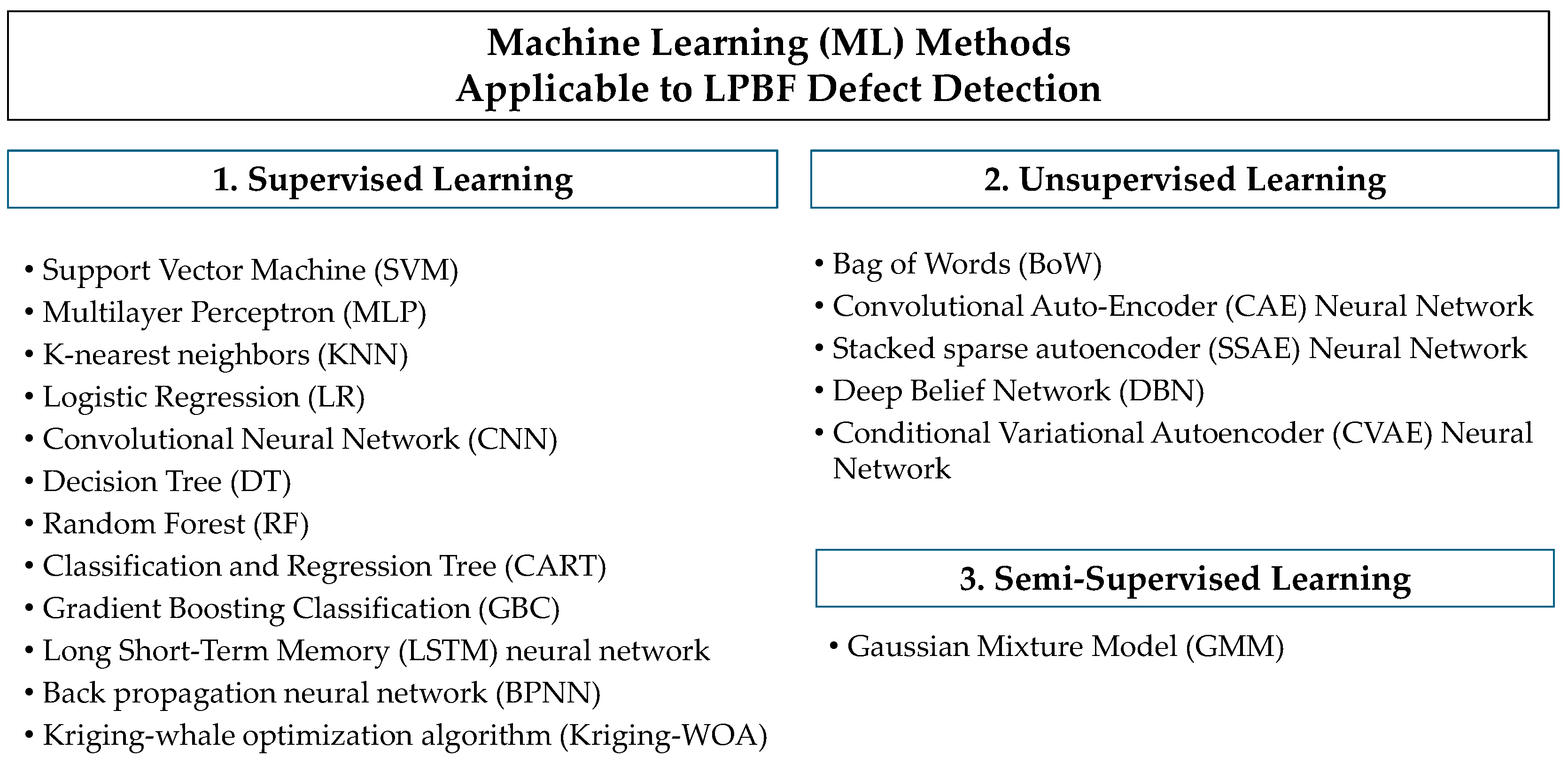
4.1. Summary of Applicable ML Methods

Machine learning (ML) methods can analyze LPBF parts by utilizing various forms of data, such as optical, thermal, and acoustic/ultrasonic, to “train” the machine algorithms to recognize surface and microstructure characteristics, including defects. A myriad of ML algorithms is used to detect LPBF defects. Supervised learning (SL) utilizes labeled datasets to train algorithms to classify and recognize LPBF defects. Reported ML techniques utilizing SL to recognize LPBF defects include the following: support vector machines (SVMs), multilayer perceptron (MLP), K-nearest neighbors (KNN), random forest (RF), logistic regression (LR), convolutional neural network (CNN), decision trees (DTs), gradient boosting classification (GBC), classification and regression tree (CART), Gaussian process classification (GPC), long short-term memory (LSTM) neural networks, back propagation neural networks (BPNNs), and the Kriging whale optimization algorithm (Kriging-WOA). Unsupervised learning (UL) conversely utilizes unlabeled datasets to train algorithms to classify and recognize LPBF defects. Reported ML techniques utilizing UL to recognize LPBF defects include the following: bag of words (BoW), the deep belief network (DBN), the convolutional auto-encoder (CAE) neural network, the stacked sparse autoencoder (SSAE) neural network, and the conditional variational autoencoder (CVAE) neural network. Semi-supervised learning (SSL) utilizes a small amount of data of the solidified portion and a large amount of undefined data to learn the general shapes and patterns of the entire data distribution, allowing for self-training and co-training. The only SSL technique currently studied in the literature for detecting LPBF defects is the Gaussian mixture model (GMM) [114]. The basics of each mentioned ML algorithm are briefly discussed below. Figure 10 lists a summary of all ML models or algorithms that are applicable for detecting LPBF part defects.
A brief definition is provided for the algorithms above for those interested in learning more about each model and how it would fit into the defect detection approach.

4.1.1. Supervised Learning (SL)

Support Vector Machine (SVM): A binary SL classifier that uses ground truth labels to train in detecting anomalies. Layerwise imagery information used for training is extracted by discretizing images into voxels. The relative difference in grayscale intensity values between voxels reported from the layerwise imagery can indicate the local part density and suggest various defects such as LOF voids (a low intensity surrounded by a high intensity) and spatter contaminants (a high intensity surrounded by a low intensity).
Multilayer Perceptron (MLP): A forward-predicting SL neural network trained iteratively on a dataset while minimizing a loss function [115]. An MLP is considered one of the most complex ML algorithm types for optimization due to the relatively high number of hyperparameters [116]. An MLP trains by giving the network an input vector containing earlier observations that can be used to output the future value of a variable. The output can be considered a posterior probability, and the node with the highest value defines the final classification. Data collected from LPBF prints can be classified based on the training data’s print quality (good, better, or best).
K-nearest neighbors (KNN): An SL algorithm that relies entirely on input data and does not consider any assumptions or generalizations [117]. The training data are first input into the algorithm to transform the raw data into feature vectors. Then, a parameter that defines the number of the nearest neighbors to be included in most of the voting process, known as “k,” is defined. “k” is frequently described as N1/2, where N equates to the dataset size used in algorithm training. A KNN model can detect LPBF defects by measuring the Euclidean distance from the sample to its k-nearest neighbors.
Logistic Regression (LR): A statistically based SL algorithm that finds the optimal hyperplane to separate examples based on their class label. It is accomplished by estimating an event’s probability for a given dataset of independent variables, also known as the logit model.
Convolutional Neural Network (CNN): An SL algorithm that consists of three layers, namely convolution (Conv), pooling, and fully connected layers. Regarding LPBF defects, the Conv layers combine input photos or image data with pooling data to create convolution blocks. A group of convolution blocks are used to realize a deep architecture. Patterns can be extracted from the multi-level image features through these groups of convolution blocks, which refine the model’s pattern recognition capabilities [118]. Extractable patterns can include defects.
Decision Tree (DT): A non-parametric SL method that predicts variables by learning data features’ decision rules and is presented as a piecewise constant approximation.
Random Forest (RF): An SL algorithm that extracts the training data to create various random DT sets. The multiple decision outcomes generated from RF models are accomplished through bootstrap (Monte Carlo) aggregating, also called “bagging.” During the algorithm’s execution, the “bags” of decision trees vote for the likely outcome of each instance. The votes ultimately determine the overall classification identity [119]. The RF model is also known as random forest classification (RFC).
Classification and Regression Tree (CART): An SL-DT model that picks input variables and evaluates split points on those variables to produce an appropriate tree. Each fork in the DT is split into predictor variables, with each fork node making a prediction at the end for the target variable. Sub-nodes are created by dividing the nodes based on a threshold value of an investigated attribute. The CART algorithm can utilize the same variables in various regions of the tree, which can help to reveal intricate interdependencies between groups of variables.
Gradient Boosting Classification (GBC): An SL algorithm that combines successive DTs that improve upon their predecessors. The new predictor is fitted to the residual errors created from the prior predictor rather than basing the predictor fitting on the data of each iteration.
Gaussian Process Classification (GPC): An SL kernel-based method that predicts class labels and uncertainties based on their proximity to training examples. The training data are assumed to be created by a Gaussian process.
Long/Short-Term Memory (LSTM) neural network: An SL algorithm that processes the sequence data with different lengths by connecting previous information to the current task, also known as a variant of a recurrent neural network (RNN).
Back propagation neural network (BPNN): An SL multilayer feed-forward neural network trained using the error backpropagation algorithm. A BPNN comprises three distinct types of layers, called output, hidden, and input layers, with each layer consisting of several neurons with activation functions and the weights between neurons.
Kriging whale optimization algorithm (Kriging-WOA): An SL Bayesian metamodel method that is a combination of the Kriging (Gaussian process regression) model and the whale optimization algorithm, which is a heuristic model based on the humpback whale’s behavior.

4.1.2. Unsupervised Learning (UL)

Bag of Words (BoW): A UL algorithm that can utilize extracted features to perform quantization to produce clusters of specified parameters. These clusters of patterns can then be classified to differentiate between images.
Convolutional Auto-Encoder (CAE) Neural Network: A UL algorithm in which the encoder and the decoder are trained using input data to a compact space and then mapped back from a latent space to a reconstructed version of the original input data. The input and output data are mutually mapped while the developed correlation is preserved.
Stacked Sparse Autoencoder (SSAE) Neural Network: A UL process that uses the hidden layer of the previous sparse auto-encoder as the input layer for the current sparse autoencoder. The output of most neurons is suppressed by adding sparse items in the training process. Each sparse auto-encoder is typically trained independently using a greedy layerwise unsupervised algorithm.
Deep Belief Network (DBN): A UL probabilistic graphical algorithm that uses data provided by individual layers for repeated training to learn a deep probabilistic model efficiently. DBNs comprise stacks of networks with symmetrically coupled stochastic binary units known as restricted Boltzmann machines (RBMs). These are determined by visible units, hidden units, and connections between visible and invisible neurons [120].
Conditional Variational Autoencoder (CVAE) Neural Network: A UL generative method that introduces an extra input into the encoder and decoder.

4.1.3. Semi-Supervised Learning (SSL)

Gaussian Mixture Model (GMM): An SSL algorithm that assumes all data points are generated from a mixed distribution of a limited number of Gaussian distributions, such that the probability distribution is described as the sum of weighted Gaussian components over each provided data point. The GMM can address situations involving different data types (labeled and unlabeled). Using data distribution trends, the GMM creates new data, which helps to alleviate ML overfitting and helps facilitate the ML model’s training process.
The data required to utilize and train AI algorithms to accurately predict and/or detect defects in LPBF metal parts are collected via a series of sensing technologies. Thus, the integration of AI and sensing technologies is essential. In the previous section, applicable AI approaches are presented. Before exploring AI’s integration with sensing technologies, the following sections briefly define the most common existing technologies and summarize applicable sensing technologies to detect specific defects associated with LPBF metal parts.

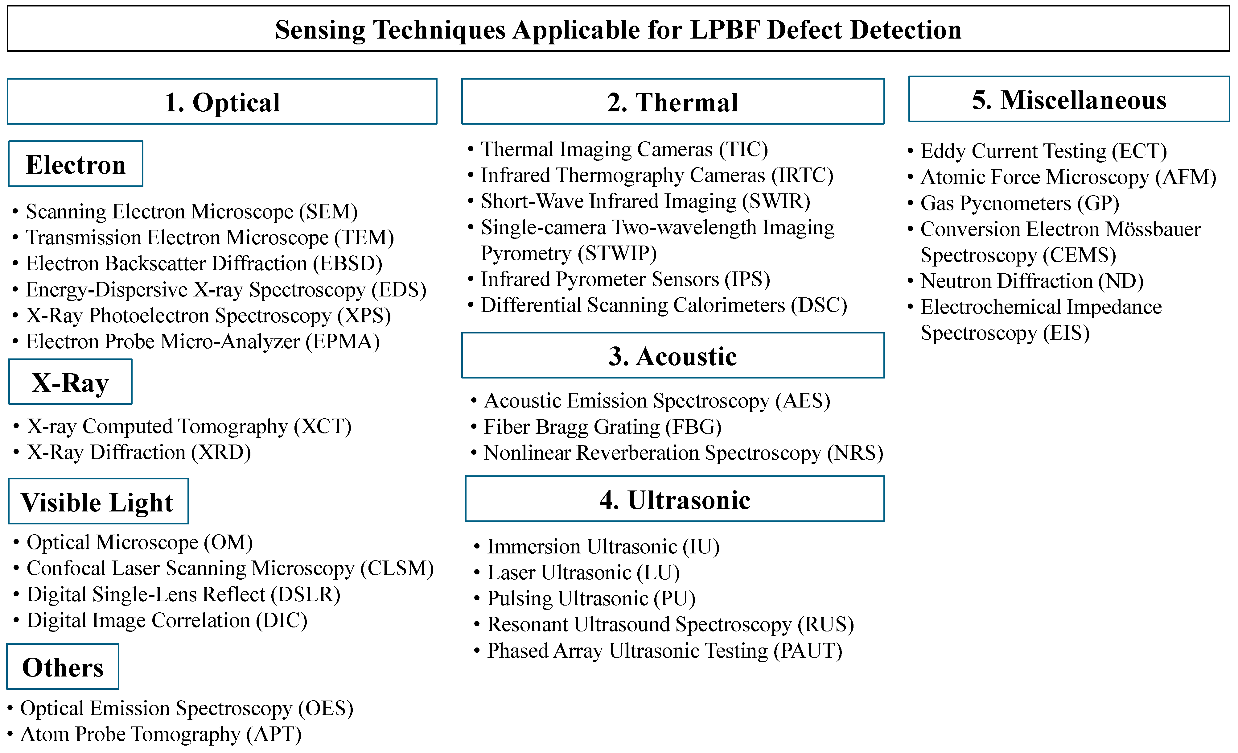
4.2. Summary of Applicable Sensing Techniques for Detecting LPBF Defects

The quality of LPBF parts can be characterized using various material characterization technologies and techniques that have been used for decades. These sensor-based techniques include optical, thermal, acoustic, ultrasonic, and other miscellaneous methods. Depending on the technology, part material, and conditions, sensing technologies allow for destructive and non-destructive analyses. Destructive techniques cause permanent sample damage and samples become unusable. On the other hand, non-destructive techniques allow for samples to remain accessible and to be used repeatedly. LPBF part analysis typically involves a combination of multiple sensing technologies to increase the information gathered on part quality and accurate defect detection. The role of sensing technologies in detecting LPBF part defects has been addressed in detail in a series of publications by the authors [3]. The previous article covered the capabilities of individual sensing technologies (destructive and non-destructive), listing their corresponding advantages and disadvantages in LPBF defect detection.
Optical-based techniques are commonly used in LPBF final print quality evaluations and the detection of defects. Optical sensors probe the sample’s structure internally or externally using electron trajectories. Sources generate optical signals that can be traced and detected within the part, including via electron and laser beams, X-rays, and more [3].
Thermal techniques are based on temperature differences and reflected light to detect defects and determine the final part quality. Thermal imaging, infrared cameras, and pyrometers are commonly implemented to monitor the LPBF melt pool during part processing. After completing melt pool solidification, they also provide information regarding the defect’s distribution, such as size and type. Additional thermal-based technology includes differential scanning calorimeters (DSCs), which monitor the thermal energy distribution during the part heating or cooling processes. The heat distribution enables monitoring transitions between different phases to identify potential defect formations.
Acoustic (resonance) techniques are reliable in detecting vibrations. They are proven to detect internal and external defects in LPBF-printed parts. The acoustic signals emitted (AE) during the printing process are collected to develop the relation between the signals and the location, providing reliable information regarding the size of defects.
Ultrasonic techniques use waves to estimate the surface quality of LPBF-printed products. The ultrasonic waves are artificially created within the sample by interference with an external wave emitter. Other techniques used to determine the LPBF metal print quality and quantitatively determine the defect’s characteristics include electromagnetic induction, probes, and pycnometers. Figure 11 summarizes all LPBF defect detection sensing technologies.

4.2.1. Recommendations for Optical-Based Sensing Technologies

Optical electron source-based technologies are designed to detect all types of defects. SEM technologies detect all defects, including balling, roughness, and vaporization. Oxidized surfaces are monitored by electron source-based technologies, except for EBSD, including surface oxidation behavior images (SEM, TEM, and EPS) and chemical composition (XPS and EPMA). LOF, gas, and keyhole properties are detected using different technologies, including SEM and TEM. EPMA provides chemical data that detect the formation of keyhole porosity. SEM, EBSD, and EDS are used to observe and detect different cracking types, while delamination is predicted using SEM. The chemical compositions are collected using EDS (EDX).
Optical X-ray-based technologies are also applicable to detect most all LBPF part defects. Surface quality, liquation cracking, and microstructural defects are monitored using XCT. XRD can initially detect surface oxidation, gas porosities, delamination, and surface roughness defects. Optical visible light-based technologies are reported to detect balling defects (OM and CLSM), surface oxidation (OM), and roughness and denudation (OM, CLSM, and DSLR). OM and CLSM can detect LOF, gas, and keyhole porosities. Other defects, including cracking, are predicted using OM and DIC, while delamination is visualized with CLSM and DSLR. Table 7 summarizes the optical-based sensing technologies that detect different LPBF part defects.

4.2.2. Recommendations for Thermal-Based Sensing Technologies

Many reported publications have shown the accuracy of thermal-sensing-based technologies in detecting most LPBF defects, except for oxidation, porosities, and delamination. Balling is detected using IRTC, surface roughness is monitored using STWIP, and denudation and vaporization defects are monitored using TIC. Furthermore, LOF and porosities are monitored using thermal sensing techniques (SWIR, SWTIP, IRTC, SWIR, and IPS) while DSC detects cracking. Table 8 summarizes the thermal-based sensing techniques that detect different LPBF part defects.

4.2.3. Recommendations for Acoustic and Ultrasonic-Based Sensing Technologies

Acoustic and ultrasonic methods have been shown to identify most LPBF part defects. Surface quality (AES and NRS), LOF porosity microstructure (FBG and NRS), and mechanical defects can be detected by acoustic sensors. Ultrasonic-based sensing technologies are limited in detecting microstructure and mechanical defects. All ultrasonic-based sensing technologies, including IU, LU, PU, RUS, and PAUT, are usable to detect LOF-formed pores and cavities. Gas porosities are detectable with IU and LU, while keyhole pores are identified using only IU. AES cracking is monitored via AES, while solidification cracking and delamination defects are effectively detected using IU and LU. Table 9 summarizes the acoustic- and ultrasonic-based techniques for monitoring and detecting different LPBF part defects.

4.3. Integrated ML Techniques and Optical Sensors

In situ layerwise imagery of the LPBF printing process is captured through many sensor types, such as cameras, microscopes, photodiode sensors, and XCT techniques. High-speed cameras such as visual-light cameras, digital single-lens reflex (DSLR) cameras, built-in powder bed cameras, and CMOSIS-sensor cameras capture in situ layerwise images of the printed part. Similarly, microscopes such as scanning electron microscopes (SEMs), confocal laser scanning microscopes (CLSMs), and optical microscopes (OMs) also capture layerwise images of scanned surfaces. Captured microscopic imagery has been shown to capture much more robust microstructure characteristics of the part surface than cameras. Photodiode sensors convert light emissions to an electrical voltage or photocurrent. Frequently, photodiode sensors are paired with optical cameras to predict defective locations based on the light emission signals. X-ray computed tomography (XCT) instruments direct narrow X-ray beams at an object to produce cross-sectional images, which can be stacked together to create a 3D image of the object.
Optical sensor data are the most popular data used to train ML algorithms to recognize and classify LPBF defects. To train ML algorithms, layerwise imagery of the LPBF printing process is collected and processed based on chosen parameters. Figure 12 presents a process schematic detailing the implementation of CT scan data into SL learning. Often, surface characteristics investigating LPBF are used to classify the part quality. For example, the layerwise image of a particular scan can be categorized into poor, medium, and high quality, specifically regarding porosity. LPBF-printed part layerwise imagery post-processing characteristics can be correlated with appearance classifications, such as surface roughness, surface morphology, and stress characteristics. Defect characteristics such as size, shape, and location can also be used to classify the quality of the LPBF-printed part. A compiled list of optical sensors integrated with ML methods for detecting LPBF defects is provided in Table 10.
A DSLR camera and XCT were utilized to capture the surface and microstructure characteristics of SS-GP1 LPBF-printed parts [172]. A linear support vector machine (SVM) detected defects such as incomplete fusions, porosities, cracks, or inclusions. A pre-trained CNN was used to detect in situ processing defects in LPBF autonomously printed parts [173]. Powder bed images were captured using a visible-light camera. An online monitoring system was developed to evaluate the quality of fusion and defect formation in every layer of Ti6Al4V LPBF-printed parts using visual camera imaging as the training input [175]. A Bayesian interface classifier was chosen to detect defective layers or regions automatically from the camera imaging. A digitally simulated CT scan with internal micropores was tested to allow for supervised ML training using a random forest (RF) model for LPBF-printed parts [119]. Similarly, a CNN-based online fault recognition system was developed using microstructure images to predict the defects due to the process in IN718 LPBF-printed parts [118]. Observed defects included internal pores and balling.
A deep-learning CNN using XCT of Ti6Al4V LPBF-printed thin-wall fins was trained to recognize defects such as inconsistent thickness, warping, and cracking [176]. A visible-light high-speed camera was utilized to study the IN718 LPBF melt pool morphology [191]. The unsupervised ML method, the bag of words (BoW) method, was used to distinguish differences between the recorded molten pools. A CMOSIS-sensor camera and a CNN were utilized to develop an in-process sensor monitoring system [174]. Researchers quantitatively extracted the microstructural features of a Ti6Al4V LPBF-printed part from SEM imaging using the random forest (RF) algorithm [177]. A DNN-based classification model for SUS316L was used for melting pool images in LPBF-printed parts [192].
A machine learning method was developed to build optimal LPBF process parameters for satisfactory surface roughness and dimensional accuracy [178]. The Kriging (Gaussian regression) model and whale optimization algorithm (WOA) were used in the data-driven framework to achieve optimal process parameters. The experimental data included surface roughness measurements taken using a surface roughness tester and surface topography measurements taken using a laser scanning confocal microscope. Sixteen groups of experiments were used to train the Kriging model. A synthetic and XCT dataset was used to train a conditional variational autoencoder (CVAE) and a CNN to predict pore occurrences in AlSi10Mg LPBF-printed parts [187]. A framework to process XCT-generated melt pool images of IN625 LPBF-printed parts was presented using a convolutional autoencoder (CAE) neural network [186]. An in-process fault detection and part quality prediction method for LPBF-printed parts was developed using a Bayesian classifier [8]. An XGBoost (XGB) model was trained to predict localized defects for SS316L LPBF-printed parts using defect data from in situ images of LPBF-printed parts as the training data [179]. The root causes of SS316L LPBF-printed part quality were analyzed using various ML classifier models, including a LR, SVM, CART, RF, XGB, MLP, KNN, and LDA [180]. A CNN-based image colorization algorithm was presented to predict tensile plane strain field components of Al6061T6 LPBF-printed part microstructures featuring porosity defects [185]. XCT image data were utilized to train neural networks (NNs) and CNNs to predict defects in images of Ti6Al4V LPBF-printed build layers [188]. A deep transfer learning (DTL) model was developed to combine transfer learning and deep CNN to perform an in situ quality inspection of LPBF-printed parts using XCT-scanned layerwise camera images [181].
The proposed DTL method successfully monitored part quality, which can help reduce porosity defects during the printing process. It was utilized to build a large dataset of stress responses of 100,000 random microstructure images to train a modified U-Net style CNN model that can predict the elastic stress fields in images of LPBF-printed parts containing defects [189]. Experiments were performed by applying the model to real LPBF microstructures with severe LOF defects. The proposed CNN model could accurately predict the structural response of LPBF microstructures containing defects. Using two high-speed imaging cameras for monitoring, the temperature profile of an SS316L LPBF was reported. The validity of several different detection classifier models was evaluated to detect various defects, including SVM, MLP, KNN, RF, and CNN models [182]. An innovative image and data processing approach was developed to extract high-accuracy level melt pool data [183]. A 2D optical microscope was used to monitor the temperature of molten pool images in situ for multitrack and multilayer printing processes. A series of models, including back propagation NN (BPNN), support vector machine (SVM), and deep belief network (DBN) models, were developed to align the feature data with porosity modes using 2D optical micrographic observations [183]. Three semi-supervised ML approaches were used to detect anomalies and defects in SS316L LPBF builds using Vgg16, ResNet50, and Xception [184]. These three approaches are CNN-based algorithms. The training image data were generated using a digital single-lens reflex camera. The influence of layer thickness, stress ratio, and defect properties of AlSi10Mg LPBF-printed parts on the fatigue life was investigated [190]. SEM imaging provided microstructure morphology and fractography data and was used to train three ML models. These models are the artificial neural network (ANN), the support vector regression (SVR), and the random forest (RF) algorithms. The RF model best predicted the fatigue life of the LPBF-printed AlSi10Mg samples.

4.4. Integrated ML Techniques and Thermal Sensors

The thermal characteristics of LPBF scans collected from thermal sensors can highlight the formation of defects and suggest the overall part quality of the build. The thermal data collected from IR cameras and pyrometers have been utilized to train ML algorithms to recognize in situ undesired anomalies such as defects. Infrared thermal or thermographic cameras use infrared (IR) radiation to create images. During the LPBF printing process, IR cameras can capture detailed thermal characteristics of the current laser scan, revealing temperature maldistributions that can affect the subsequent scan. Figure 13 displays how an IR camera can highlight the position and geometry of various defects and undesired anomalies. The IR cameras integrated with ML algorithms for detecting defects reported in the literature include forward-looking infrared (FLIR) and short-wave infrared imaging (SWIR) cameras. Pyrometers are remote sensing thermometers that can measure the amount of thermal radiation emitted from the probed surface. Pyrometers integrated with ML algorithms for detecting defects reported in the literature include single-camera two-wavelength imaging pyrometers (STWIPs) and dual-wavelength imaging pyrometers. A compiled list of thermal sensors integrated with ML methods for detecting LPBF defects is provided in Table 11.
A semi-supervised ML algorithm based on the GMM was introduced to investigate balling and overheating phenomena in IN718 LPBF-printed parts [193]. Photodiode sensors extracted thermal radiation and plasma emissions from the melt pool. A CNN model was utilized to analyze thermographic off-axis imaging to detect LPBF printing defects [195]. Delamination and splatter defects were recognized using the proposed model. The model correlated the thermal history and subsurface porosity of Ti6Al4V LPBF-printed parts under various print conditions [194]. A high-speed infrared camera was used to obtain non-normalized surface temperatures, and a synchrotron x-ray imaging system was used to obtain porosity formation information. Several different ML algorithms were trained to recognize the formation of defects during the printing process, including LR, RF, GBC, and GPC.
The micropore distributions in the SS304 LPBF-printed part were predicted using in situ thermographic data and ML [196]. A short-wave infrared (SWIR) imaging camera was used to monitor the spatial and temporal thermal features. Various supervised ML models, including K-nearest neighbor (KNN), random forest (RF), decision tree (DT), multi-layer perceptron (MLP), logistic regression (LR), and AdaBoost models, were trained to detect micropores [197]. A dual-wavelength imaging pyrometer was developed to train various classifier models to detect LPBF defects. The classifier models included KNN, SVM, LR, and CNN. A photodiode sensing system and a pyrometer generated the training data. A CNN-based ML method was employed to retrieve the spatial distribution of melt pool signatures within the coordinate system of the corresponding part [152]. Additionally, by mapping the STWIP-measured melt pool signatures to the registered melt pool coordinates, the melt pool signature maps were reconstructed. The in-process surface topography information generated from the melt pool signature maps can aid in characterizing and detecting defects.
Figure 13. Graphical description of melt pool data extraction using in situ dual-wavelength imaging pyrometer and an SVM machine learning approach [197].
Applsci 14 08534 g013
An online continuous flaw detection method was presented that combines photodiode signals and melt pool temperature for LPBF-generated products. A set of camera images recorded at a high resolution and speed were used to characterize the molten zone [199]. A correlation connecting the photodiode signal and average melt pool temperature was made using three deep learning algorithms, namely back propagation neural network (BPNN), stacked sparse autoencoder (SSAE), and long short-term memory (LSTM) algorithms. The CNN-based monitoring technique was implemented for SS316L LPBF printing, which utilizes infrared imaging data [154]. A YOLOV5 target recognition algorithm capable of recognizing macro-defects was implemented. The experimental results mentioned the detection of the laser spot, inclusion, surface spheroidization, and scraper damage warping but did not include micro-defects and the molten pool environment. A stacked group of autoencoders was utilized to reduce noises in raw melt pool monitoring images, and a CNN was used to identify the scan direction associated with an individual melt pool monitoring image [198].

4.5. Integrated ML Techniques and Acoustic/Ultrasonic Sensors

Acoustic and ultrasonic sensors collect the vibrational waves propagating on or through the surface of a material. Regarding LPBF defect detection, acoustic sensing techniques have been used to monitor the quality of the LPBF printing process. The recorded sound from the laser hitting the powder substrate during printing can be processed to hint towards porosities and undesired anomalies. The graphical diagram showing how AE signals can capture melt pool behavior in the LPBF process is provided in Figure 14. The acoustic sensor types used to train ML algorithms to recognize defects include acoustic emission (AE) sensors, fiber Bragg grating (FBG) sensors, and microphones. A compiled list of acoustic/ultrasonic sensors integrated with ML methods for detecting LPBF defects is provided in Table 12.
An ML algorithm was utilized to recognize various LPBF defects, including porosities, delamination, and crack propagation [200]. The training data were produced using an airborne resonant acoustic emissions sensor. Two CNN algorithms were trained based on variational auto-encoder and general adversarial network models. Acoustic signals utilizing a fiber Bragg grating sensor were collected and taught by a CNN-based classifier to separate the acoustic signals of dissimilar feature quality [161]. The dissimilar acoustic features can hint at information about the locations of individual defects, including the formation of deep keyhole channels, tubular defects, and LOF defects. A novel method for defect detection within LPBF-printed parts using acoustic emission signals and deep belief networks (DBNs) was developed [159]. The DBNs achieved high defect detection rates, differentiating between five melted states without signal preprocessing.
Acoustic signal and image features were used to train DBN and CNN models to recognize different melting states in the LPBF printing process of SS304L [201]. An SVM algorithm was used to identify and classify defect patterns, including underheating and overheating states. Acoustic emission (AE) signals and various ML methods were integrated to develop an in situ crack detection system for LPBF-printed parts. The investigated ML methods included logistic regression, SVM, RF, and Gaussian process classifier models [202]. Using a CNN, an acoustic monitoring system was utilized to classify three processing regimes: LOF pores, conduction modes, and keyhole pores. An ultrasound microphone collected the acoustic emission signals [203]. A supervised ML technique was used to analyze XCT imagery for defects. Pre- and post-laser scan layerwise imagery, acoustic and multi-spectral emissions, and scan vector trajectory-derived information also contributed to the process footprint [204].
Table 12. A compiled list of acoustic/ultrasonic sensors integrated with ML methods for detecting LPBF defects.
MaterialSensor TypeML Technique(s) Defects Observed
CL 20ES Stainless Steel [161]Fiber Bragg grating (FBG) sensorSCNN, Tubular voids, gas porosity, LOF, insufficient bonding
SS304L [159,201]Acoustic emission sensor, PCB microphoneDBN, MLP, SVM, DBN, CNN, SVMBalling, overheating, underheating
IN718 [200]Airborne resonant acoustic emissions sensorCNNBalling, LOF pores, keyhole pores, delamination, crack propagation
Ti6Al4V [204]Layerwise electro-optical imagery, acoustic microphone, multi-spectral emissions, scan vectorsCNNKeyholing, under-melting, balling
Al92Mn6Ce2 [202]Acoustic emission sensorLR, SVM, RF, GPCGas pores, low fusion, cracks
SS316L [203]Ultrasound microphoneCNNLOF pores, keyhole pores

5. Conclusions

The integrative potential of LPBF-printed parts in various innovative applications depends on its ability to compete with traditionally manufactured parts regarding the produced parts’ infallibility and robustness in terms of the quality of parts. Despite the high accuracy of LPBF printing, defect formations are inevitable. Reducing or eliminating factors that lead to final part defects is crucial to producing parts of satisfactory quality. Sensing technologies, numerical methods, and artificial intelligence (AI) algorithms are utilized to predict and identify LPBF defects. This review explains the common LPBF-related defects (geometrical/dimensional, surface quality, microstructure, and mechanical) and the causes generally associated with them. Melt pool defect modeling has experienced advances, such as the incorporation of the finite element, finite volume, and analytical methods. Combinations of sensing technologies and statistical modeling with numerical methods (FEM) for the mechanical modeling of lattice structures (reconstructed CT scans, statistically driven defects, and embedded defects) are elaborated. The applicable ML algorithms typically found in LPBF defect detection efforts and standard sensing techniques are summarized. The integration of ML techniques with optical, thermal, and acoustic/ultrasonic techniques is explained.
Integrating AI techniques with sensing technologies and numerical modeling has allowed accelerated optimization and the in situ auto-tuning of process parameters. AI integration has helped to improve our understanding of certain defect formations, assisting sensing technologies in predicting and detecting defects based on the trained algorithm’s criteria. With the continuing push for rapid innovation in many industries, LPBF-printed parts are expected to advance significantly with the use of many technologies. In the foreseeable future, AI-integrated sensing technologies will continue to play a more significant role in LPBF defect detection methodologies, providing enhanced design freedom and reliability for many industries.

Author Contributions

Conceptualization, S.W. and A.A.; investigation, S.W., original draft preparation, S.W. and A.A.; writing—review and editing, S.W. and A.A. All authors have read and agreed to the published version of the manuscript.

Funding

This work was funded by internal funding from Idaho State University (ISU) and the Center for Advanced Energy Studies (CAES), 2023-ACEA01.

Institutional Review Board Statement

Not applicable.

Informed Consent Statement

Not applicable.

Data Availability Statement

Not applicable.

Conflicts of Interest

The authors declare that they have no known competing financial interests or personal relationships that could have appeared to influence the work reported in this paper.

References

  1. Herzog, D.; Seyda, V.; Wycisk, E.; Emmelmann, C. Additive manufacturing of metals. Acta Mater. 2016, 117, 371–392. [Google Scholar] [CrossRef]
  2. Cai, C.; Zhou, K. Chapter 7—Metal additive manufacturing. In Digital Manufacturing: The Industrialization of Art to Part 3D Additive Printing; Elsevier: Amsterdam, The Netherlands, 2022; pp. 247–298. [Google Scholar] [CrossRef]
  3. Guillen, D.; Wahlquist, S.; Ali, A. Critical Review of LPBF Metal Print Defects Detection: Roles of Selective Sensing Technology. Appl. Sci. 2024, 14, 6718. [Google Scholar] [CrossRef]
  4. Malekipour, E.; El-Mounayri, H. Common defects and contributing parameters in powder bed fusion AM process and their classification for online monitoring and control: A review. Int. J. Adv. Manuf. Technol. 2018, 95, 527–550. [Google Scholar] [CrossRef]
  5. Qiu, C.; Panwisawas, C.; Ward, M.; Basoalto, H.C.; Brooks, J.W.; Attallah, M.M. On the role of melt flow into the surface structure and porosity development during selective laser melting. Acta Mater. 2015, 96, 72–79. [Google Scholar] [CrossRef]
  6. Shen, Y.F.; Gu, D.; Pan, Y.F. Balling Process in Selective Laser Sintering 316 Stainless Steel Powder. Key Eng. Mater. 2006, 316, 315–316. [Google Scholar] [CrossRef]
  7. Simonelli, M.; Tuck, C.; Aboulkhair, N.T.; Maskery, I.; Ashcroft, I.; Wildman, R.D.; Hague, R. A study on the laser spatter and the oxidation reactions during selective laser melting of 316l stainless steel, Al-Si10-Mg, and Ti-6Al-4V. Metall. Mater. Trans. 2015, 46, 3842–3851. [Google Scholar] [CrossRef]
  8. Felix, S.; Majumder, S.R.; Mathews, H.K.; Lexa, M.; Lipsa, G.; Ping, X.; Roychowdhury, S.; Spears, T. In situ process quality monitoring and defect detection for direct metal laser melting. Sci. Rep. 2022, 12, 8503. [Google Scholar] [CrossRef]
  9. Chowdhury, S.; Yadiah, N.; Prakash, C.; Ramakrishna, S.; Dixit, S.; Gupta, L.R.; Buddhi, D. Laser powder bed fusion: A state-of-the-art review of the technology, materials, properties & defects, and numerical modeling. J. Mater. Res. Technol. 2022, 20, 2109–2172. [Google Scholar] [CrossRef]
  10. Gusarov, A.; Yadroitsev, I.; Bertrand, P.; Smurov, I. Model of radiation and heat transfer in laser-powder interaction zone at selective laser melting. J. Heat Transf. 2009, 131, 072101. [Google Scholar] [CrossRef]
  11. Matthews, M.J.; Guss, G.; Khairallah, S.A.; Rubenchik, A.M.; Depond, P.J.; King, W.E. Denudation of metal powder layers in laser powder bed fusion. Acta Mater. 2016, 114, 33–42. [Google Scholar] [CrossRef]
  12. Yadroitsev, I.; Bertrand, P.; Smurov, I. Parametric analysis of the selective laser melting process. Appl. Surf. Sci. 2007, 253, 8064–8069. [Google Scholar] [CrossRef]
  13. Cao, X.; Jahazi, M.; Immarigeon, J.; Wallace, W. A review of laser welding techniques for magnesium alloys. J. Mater. Process. Technol. 2006, 171, 188–204. [Google Scholar] [CrossRef]
  14. Rombout, M.; Kruth, J.P.; Froyen, L.; Mercelis, P. Fundamentals of Selective laser melting of alloyed steel powders. CIRP Ann. 2006, 55, 187–192. [Google Scholar] [CrossRef]
  15. Eliasu, A.; Czekanski, A.; Boakye-Yiadom, S. Effect of laser powder bed fusion parameters on the microstructural evolution and hardness of 316L stainless steel. Int. J. Adv. Manuf. Technol. 2021, 113, 2651–2669. [Google Scholar] [CrossRef]
  16. Heiden, M.J.; Deibler, L.A.; Rodelas, J.M.; Koepke, J.R.; Tung, D.J.; Saiz, D.J.; Jared, B.H. Evolution of 316L stainless steel feedstock due to laser powder bed fusion process. Addit. Manuf. 2019, 25, 84–103. [Google Scholar] [CrossRef]
  17. Gordon, J.V.; Narra, S.P.; Cunningham, R.W.; Liu, H.; Chen, H.; Suter, R.M.; Beuth, J.L.; Rollett, A.D. Defect structure process maps for laser powder bed fusion additive manufacturing. Addit. Manuf. 2020, 36, 101552. [Google Scholar] [CrossRef]
  18. Liu, Y.J.; Li, S.J.; Wang, H.L.; Hou, W.T.; Hao, Y.L.; Yang, R. Microstructure, defects and mechanical behavior of beta-type titanium porous structures manufactured by electron beam melting and selective laser melting. Acta Mater. 2016, 113, 56–67. [Google Scholar] [CrossRef]
  19. Simson, T.; Emmel, A.; Dwars, A.; Böhm, J. Residual stress measurements on AISI 316L samples manufactured by selective laser melting. Addit. Manuf. 2017, 17, 183–189. [Google Scholar] [CrossRef]
  20. Chen, Y.; Zhang, K.; Huang, J.; Hosseini, S.R.E.; Li, Z. Characterization of heat affected zone liquation cracking in laser additive manufacturing of Inconel 718. Mater. Des. 2016, 90, 586–594. [Google Scholar] [CrossRef]
  21. Marchese, G.; Basile, G.; Bassini, E.; Aversa, A.; Lombardi, M.; Ugues, D.; Fino, P.; Biamino, S. Study of the microstructure and cracking mechanisms of Hastelloy X produced by LPBF. Materials 2018, 11, 106. [Google Scholar] [CrossRef]
  22. Narasimharaju, S.R.; Zeng, W.; See, T.L.; Zhu, Z.; Scott, P.; Jiang, X.; Lou, S. A comprehensive review on laser powder bed fusion of steels: Processing, microstructure, defects and control methods, mechanical properties, current challenges, and future trends. J. Manuf. Process. 2022, 75, 375–414. [Google Scholar] [CrossRef]
  23. Brennan, M.C.; Keist, J.S.; Palmer, T.A. Defects in Metal Additive Manufacturing Processes. J. Mater. Eng. Perform. 2021, 30, 4808–4818. [Google Scholar] [CrossRef]
  24. Kempen, K.; Thijs, L.; Vrancken, B.; Buls, S.; Humbeeck, J.V.; Kruth, J.-P. Producing crack-free, high-density M2 HSS parts by selective laser melting: Pre-heating the baseplate. In Proceedings of the 2013 International Solid Freeform Fabrication Symposium, Austin, TX, USA, 12–14 August 2013. [Google Scholar]
  25. DebRoy, T.; Wei, H.L.; Zuback, J.S.; Mukherjee, T.; Elmer, J.W.; Milewski, J.O.; Beese, A.M.; Wilson-Heid, A.; De, A.; Zhang, W. Additive manufacturing of metallic components–Process, structure, and properties. Prog. Mater. Sci. 2018, 92, 112–224. [Google Scholar] [CrossRef]
  26. Hussein, A.; Hao, L.; Yan, C.; Everson, R. Finite Element Simulation of the Temperature and Stress Fields in Single Layers Built Without-support in Selective Laser Melting. Mater. Des. 2013, 52, 638–647. [Google Scholar] [CrossRef]
  27. Khairallah, S.; Anderson, A.; Rubenchik, A.; King, W. Laser powder-bed fusion additive manufacturing: Physics of complex melt flow and formation mechanisms of pores, spatter, and denudation zones. Acta Mater. 2016, 108, 36–45. [Google Scholar] [CrossRef]
  28. Luo, Z.; Zhao, Y. Numerical Simulation of part-level temperature fields during selective laser melting of stainless steel 316L. Int. J. Adv. Manuf. Technol. 2019, 104, 1615–1635. [Google Scholar] [CrossRef]
  29. Martin, A.A.; Calta, N.P.; Khairallah, S.A.; Wang, J.; Depond, P.J.; Fong, A.Y.; Thampy, V.; Guss, G.M.; Kiss, A.M.; Stone, K.H.; et al. Dynamics of pore formation during laser powder bed fusion additive manufacturing. Nat. Commun. 2019, 10, 1987. [Google Scholar] [CrossRef]
  30. Khan, K.; Mohr, G.; Hilgenberg, K.; De, A. Probing a novel heat source model and adaptive remeshing technique to simulate laser powder bed fusion with experimental validation. Comp. Mater. Sci. 2020, 181, 109752. [Google Scholar] [CrossRef]
  31. Forien, J.-B.; Guss, G.; Khairallah, S.; Smith, W.; DePond, P.; Matthews, M.; Calta, N. Detecting missing struts in metallic micro-lattices using high speed melt pool thermal monitoring. Addit. Manuf. Lett. 2023, 4, 100112. [Google Scholar] [CrossRef]
  32. Parry, L.; Ashcroft, I.A.; Wildman, R.D. Understanding the effect of laser scan strategy on residual stress in selective laser melting through thermo-mechanical simulation. Addit. Manuf. 2016, 12, 1–15. [Google Scholar] [CrossRef]
  33. Vastola, G.; Zhang, G.; Pei, Q.X.; Zhang, Y.-W. Modeling the Microstructure Evolution During Additive Manufacturing of Ti6Al4V: A Comparison Between Electron Beam Melting and Selective Laser Melting. JOM 2016, 68, 1370–1375. [Google Scholar] [CrossRef]
  34. Chiumenti, M.; Neiva, E.; Salsi, E.; Cervera, M.; Badia, S.; Moya, J.; Chen, Z.; Lee, C.; Davies, C. Numerical modeling and experimental validation in Selective Laser Melting. Addit. Manuf. 2017, 18, 171–185. [Google Scholar] [CrossRef]
  35. Queva, A.; Guillemot, G.; Moriconi, C.; Metton, C.; Bellet, M. Numerical study of the impact of vaporization on melt pool dynamics in laser powder bed fusion-application to IN718 and Ti–6Al–4V. Addit. Manuf. 2020, 35, 101249. [Google Scholar] [CrossRef]
  36. Mayi, Y.; Dal, M.; Peyre, P.; Bellet, M.; Metton, C.; Moriconi, C.; Fabbro, R. Transient dynamics and stability of keyhole at threshold in laser powder bed fusion regime investigated by finite element modeling. J. Laser Appl. 2021, 33, 012024. [Google Scholar] [CrossRef]
  37. Dugast, F.; Apostolou, P.; Fernandez, A.; Dong, W.; Chen, Q.; Strayer, S.; Wicker, R.; To, A.C. Part-scale thermal process modeling for laser powder bed fusion with matrix-free method and GPU computing. Addit. Manuf. 2021, 37, 101732. [Google Scholar] [CrossRef]
  38. Carraturo, M.; Kollmannsberger, S.; Reali, A.; Auricchio, F.; Rank, E. An immersed boundary approach for residual stress evaluation in selective laser melting processes. Addit. Manuf. 2021, 46, 102077. [Google Scholar] [CrossRef]
  39. Jin, P.; Tang, Q.; Song, J.; Feng, Q.; Guo, F.; Fan, X.; Jin, M.; Wang, F. Numerical investigation of the mechanism of interfacial dynamics of the melt pool and defects during laser powder bed fusion. Opt. Laser Technol. 2021, 143, 107289. [Google Scholar] [CrossRef]
  40. Promoppatum, P.; Srinivasan, R.; Quek, S.S.; Msolli, S.; Shukla, S.; Johan, N.S.; Veen, S.v.d.; Jhon, M.H. Quantification and prediction of lack-of-fusion porosity in the high porosity regime during laser powder bed fusion of Ti-6Al-4V. J. Mater. Process. Technol. 2022, 300, 117426. [Google Scholar] [CrossRef]
  41. Mishra, A.K.; Kumar, A. Govind Development and validation of a material evaporation assisted thermal model for time-efficient calculation of thermal and solidification parameters during laser powder bed fusion process for Ti6Al4V. Addit. Manuf. 2023, 66, 103453. [Google Scholar] [CrossRef]
  42. Promoppatum, P.; Chayasombat, B.; Soe, A.; Sombatmai, A.; Sato, Y.; Suga, T.; Tsukamoto, M. In-situ modification of thermal, microstructural, and mechanical responses by altering scan lengths in laser powder bed fusion additive manufacturing of Ti-6Al-4V. Opt. Laser Technol. 2023, 164, 109525. [Google Scholar] [CrossRef]
  43. Wang, Y.; Chen, C.; Qi, Y.; Zhu, H. Residual stress reduction and surface quality improvement of dual-laser powder bed fusion. Addit. Manuf. 2022, 71, 103565. [Google Scholar] [CrossRef]
  44. Criales, L.; Arısoy, Y.; Özel, T. Sensitivity analysis of material and process parameters in finite element modeling of selective laser melting of Inconel 625. Int. J. Adv. Manuf. Technol. 2016, 86, 2653–2666. [Google Scholar] [CrossRef]
  45. Özel, T.; Arısoy, Y.; Criales, L. Computational Simulation of Thermal and Spattering Phenomena and Microstructure in Selective Laser Melting of Inconel 625. Phys. Procedia 2016, 83, 1435–1443. [Google Scholar] [CrossRef]
  46. Gouge, M.; Denlinger, E.; Irwin, J.; Li, C.; Michaleris, P. Experimental validation of thermo-mechanical part-scale modeling for laser powder bed fusion processes. Addit. Manuf. 2019, 29, 100771. [Google Scholar] [CrossRef]
  47. Kim, J.; Lee, S.; Hong, J.-K.; Kang, N.; Choi, Y. Calibration of laser penetration depth and absorptivity in finite element method-based modeling of powder bed fusion melt pools. Metals Mater. Int. 2020, 26, 891–902. [Google Scholar] [CrossRef]
  48. Luo, Z.; Zhao, Y. Efficient thermal finite element modeling of selective laser melting of Inconel 718. Comp. Mech. 2020, 65, 763–787. [Google Scholar] [CrossRef]
  49. Shrivastava, A.; Kumar, S.A.; Rao, S. A numerical modeling approach for prediction of distortion in LPBF processed Inconel 718. Mater. Proc. 2021, 44 Pt 6, 4233–4238. [Google Scholar] [CrossRef]
  50. Grange, D.; Queva, A.; Guillemot, G.; Bellet, M.; Bartout, J.-D.; Colin, C. Effect of processing parameters during the laser beam melting of Inconel 738: Comparison between simulated and experimental melt pool shape. J. Mater. Process. Technol. 2021, 289, 116897. [Google Scholar] [CrossRef]
  51. Shahabad, S.I.; Zhang, Z.; Keshavarzkermani, A.; Ali, U.; Mahmoodkhani, Y.; Esmaeilizadeh, R.; Bonakdar, A.; Toyserkani, E. Heat source model calibration for thermal analysis of laser powder-bed fusion. Int. J. Adv. Manuf. Technol. 2020, 106, 3367–3379. [Google Scholar] [CrossRef]
  52. Mishra, A.K.; Kumar, A. Computational analysis of the thermo-hydrodynamic transport processes during substrate re-melting in laser powder bed fusion of AlSi10Mg. Therm. Sci. Eng. Prog. 2023, 39, 101698. [Google Scholar] [CrossRef]
  53. Zhang, Z.-D.; Shahabad, S.; Ibhadode, O.; Dibia, C.; Bonakdar, A.; Toyserkani, E. 3-Dimensional heat transfer modeling for laser powder bed fusion additive manufacturing using parallel computing and adaptive mesh. Opt. Laser Technol. 2023, 158 Pt A, 108839. [Google Scholar] [CrossRef]
  54. Wang, Y.; Ji, X.; Liang, S. Analytical modeling of temperature distribution in laser powder bed fusion with different scan strategies. Opt. Laser Technol. 2023, 157, 108708. [Google Scholar] [CrossRef]
  55. Tang, C.; Tan, J.; Wong, C. A numerical investigation on the physical mechanisms of single-track defects in selective laser melting. Int. J. Heat Mass Transf. 2018, 126 Pt B, 957–968. [Google Scholar] [CrossRef]
  56. Anwar, A.B.; Ibrahim, I.H.; Pham, Q.-C. Spatter transport by inert gas flow in selective laser melting: A Simulation study. Powder Technol. 2019, 352, 103–116. [Google Scholar] [CrossRef]
  57. Yao, D.; Wang, J.; Luo, H.; Wu, Y.; An, X. Thermal behavior and control during multi-track laser powder bed fusion of 316 L stainless steel. Addit. Manuf. 2023, 70, 103562. [Google Scholar] [CrossRef]
  58. Wei, H.; Cao, Y.; Liao, W.; Liu, T. Mechanisms on inter-track void formation and phase transformation during laser Powder Bed Fusion of Ti-6Al-4V. Addit. Manuf. 2020, 34, 101221. [Google Scholar] [CrossRef]
  59. Liu, B.; Fang, G.; Lei, L.; Liu, W. Experimental and numerical exploration of defocusing in Laser Powder Bed Fusion (LPBF) as an effective processing parameter. Opt. Laser Technol. 2022, 149, 107846. [Google Scholar] [CrossRef]
  60. Aggarwal, A.; Shin, Y.C.; Kumar, A. Investigation of the transient coupling between the dynamic laser beam absorptance and the melt pool—vapor depression morphology in laser powder bed fusion process. Int. J. Heat Mass Transf. 2023, 201 Pt 2, 123663. [Google Scholar] [CrossRef]
  61. Cook, P.; Ritchie, D. Determining the laser absorptivity of Ti-6Al-4V during laser powder bed fusion by calibrated melt pool simulation. Opt. Laser Technol. 2023, 162, 109247. [Google Scholar] [CrossRef]
  62. Li, E.; Shen, H.; Wang, L.; Wang, G.; Zhou, Z. Laser shape variation influence on melt pool dynamics and solidification microstructure in laser powder bed fusion. Addit. Manuf. Letters 2023, 6, 100141. [Google Scholar] [CrossRef]
  63. Yang, X.; Li, Y.; Li, B. Formation mechanisms of lack of fusion and keyhole-induced pore defects in laser powder bed fusion process: A numerical study. Int. J. Therm. Sci. 2023, 188, 108221. [Google Scholar] [CrossRef]
  64. Dai, D.; Gu, D. Tailoring surface quality through mass and momentum transfer modeling using a volume of fluid method in selective laser melting of TiC/AlSi10Mg powder. Int. J. Mach. Tools Manuf. 2015, 88, 95–107. [Google Scholar] [CrossRef]
  65. He, Q.; Xia, H.; Liu, J.; Ao, X.; Lin, S. Modeling and numerical studies of selective laser melting: Multiphase flow, solidification and heat transfer. Mater. Des. 2020, 196, 109115. [Google Scholar] [CrossRef]
  66. Chu, F.; Li, E.; Shen, H.; Chen, Z.; Li, Y.; Liu, H.; Min, S.; Tian, X.; Zhang, K.; Zhou, Z.; et al. Influence of powder size on defect generation in laser powder bed fusion of AlSi10Mg alloy. J. Manuf. Process. 2023, 94, 183–195. [Google Scholar] [CrossRef]
  67. Lee, J.; Prabhu, V. Simulation Modelling for optimal control of additive manufacturing processes. Addit. Manuf. 2016, 12, 197–203. [Google Scholar] [CrossRef]
  68. Sun, Z.; Chueh, Y.H.; Li, L. Multiphase mesoscopic Simulation of multiple and functionally gradient materials laser powder bed fusion additive manufacturing processes. Addit Manuf. 2020, 35, 101448. [Google Scholar] [CrossRef]
  69. Khorasani, M.; Ghasemi, A.; Leary, M.; O’Neil, W.; Gibson, I.; Cordova, L.; Rolfe, B. Numerical and analytical investigation on meltpool temperature of laser-based powder bed fusion of IN718. Int. J. Heat Mass Transf. 2021, 177, 121477. [Google Scholar] [CrossRef]
  70. Feng, S.; Kamat, A.M.; Sabooni, S.; Pei, Y. Experimental and numerical investigation of the origin of surface roughness in laser powder bed fused overhang regions. Virtual Phys. Prototype 2021, 16, S66–S84. [Google Scholar] [CrossRef]
  71. Gu, H.; Wei, C.; Li, L.; Ryan, M.; Setchi, R.; Han, Q.; Qian, L. Numerical and experimental study of molten pool behaviour and defect formation in multi-material and functionally graded materials laser powder bed fusion. Adv. Powder Technol. 2021, 32, 4303–4321. [Google Scholar] [CrossRef]
  72. Ninpetch, P.; Kowitwarangkul, P.; Mahathanabodee, S.; Chalermkarnnon, P.; Rattanadecho, P. Computational investigation of thermal behavior and molten metal flow with moving laser heat source for selective laser melting process. Case Studies Therm. Eng. 2021, 24, 100860. [Google Scholar] [CrossRef]
  73. Qu, M.; Guo, Q.; Escano, L.I.; Clark, S.J.; Fezzaa, K.; Chen, L. Mitigating keyhole pore formation by nanoparticles during laser powder bed fusion additive manufacturing. Addit. Manuf. Letter 2022, 3, 100068. [Google Scholar] [CrossRef]
  74. Aliyu, A.A.A.; Poungsiri, K.; Shinjo, J.; Panwisawas, C.; Reed, R.C.; Puncreobutr, C.; Tumkanon, K.; Kuimalee, S.; Lohwongwatana, B. Additive manufacturing of tantalum scaffolds: Processing, microstructure and process-induced defects. Int. J. Refract. Met. Hard Mater. 2023, 112, 106132. [Google Scholar] [CrossRef]
  75. Li, Q.; Jiang, W.-G.; Qin, Q.-H.; Tu, Z.-X.; Li, D.-S. Particle-scale computational fluid dynamics study on surface morphology of GH4169 superalloy during multi-laser powder bed fusion with low energy density. J. Manuf. Process. 2023, 92, 287–296. [Google Scholar] [CrossRef]
  76. Lindström, V.; Lupo, G.; Yang, J.; Turlo, V.; Leinenbach, C. A simple scaling model for balling defect formation during laser powder bed fusion. Addit. Manuf. 2023, 63, 103431. [Google Scholar] [CrossRef]
  77. Liu, M.; Wei, K.; Zeng, X. High power laser powder bed fusion of AlSi10Mg alloy: Effect of layer thickness on defect, microstructure, and mechanical property. Mater. Sci. Eng. A 2022, 842, 143107. [Google Scholar] [CrossRef]
  78. Zeng, K.; Pal, D.; Gong, H.; Patil, N.; Stucker, B. Comparison of 3DSIM thermal modeling of selective laser melting using new dynamic meshing method to ANSYS. Mater. Sci. Technol. 2015, 31, 945–956. [Google Scholar] [CrossRef]
  79. Ganeriwala, R.; Zohdi, T. A coupled discrete element-finite difference model of selective laser sintering. Granul. Matter 2016, 18, 21. [Google Scholar] [CrossRef]
  80. Ganeriwala, R.K.; Strantza, M.; King, W.E.; Clausen, B.; Phan, T.Q.; Levine, L.E.; Brown, D.W.; Hodge, N.E. Evaluation of a thermomechanical model for prediction of residual stress during laser powder bed fusion of Ti-6Al-4V. Addit. Manuf. 2019, 27, 489–502. [Google Scholar] [CrossRef]
  81. Ning, J.; Sievers, D.E.; Garmestani, H.; Liang, S.Y. Analytical Modelling of Part Porosity in Metal Additive Manufacturing. Int. J. Mech. Sci. 2020, 172, 105428. [Google Scholar] [CrossRef]
  82. Duong, E.; Masseling, L.; Knaak, C.; Dionne, P.; Megahed, M. Scan path resolved thermal modeling of LPBF. Addit. Manuf. Lett. 2022, 3, 100047. [Google Scholar] [CrossRef]
  83. Lüthi, C.; Afrasiabi, M.; Bambach, M. An adaptive smoothed particle hydrodynamics (SPH) scheme for efficient melt pool simulations in additive manufacturing. Comp. Math. Appl. 2023, 139, 7–27. [Google Scholar] [CrossRef]
  84. Wang, W.; Garmestani, H.; Liang, S.Y. Prediction of upper surface roughness in laser powder bed fusion. Metals 2022, 12, 11. [Google Scholar] [CrossRef]
  85. Mirkoohi, E.; Liang, S.Y.; Tran, H.C.; Lo, Y.L.; Chang, Y.C.; Lin, H.Y. Mechanics modeling of residual stress considering effect of preheating in laser powder bed fusion. J. Manuf. Mater. Process. 2021, 5, 46. [Google Scholar] [CrossRef]
  86. Siddique, S.; Muhammad, I.; Rauer, M.; Kaloudis, M.; Wycisk, E.; Emmelmann, C.; Walther, F. Computed tomography for characterization of fatigue performance of selective laser melted parts. Mater. Des. 2015, 83, 661–669. [Google Scholar] [CrossRef]
  87. Amani, Y.; Dancette, S.; Delroisse, P.; Simar, A.; Maire, E. Compression behavior of lattice structures produced by selective laser melting: X-ray tomography based experimental and finite element approaches. Acta Mater. 2018, 159, 395–407. [Google Scholar] [CrossRef]
  88. Melancon, D.; Bagheri, Z.S.; Johnston, R.B.; Liu, L.; Tanzer, M.; Pasini, D. Mechanical characterization of structurally porous biomaterials built via additive manufacturing: Experiments, predictive models, and design maps for load-bearing bone replacement implants. Acta Biomater. 2017, 63, 350–368. [Google Scholar] [CrossRef]
  89. Boniotti, L.; Beretta, S.; Patriarca, L.; Rigoni, L.; Foletti, S. Experimental and numerical investigation on compressive fatigue strength of lattice structures of AlSi7Mg manufactured by SLM. Int. J. Fatigue 2019, 128, 105181. [Google Scholar] [CrossRef]
  90. Wang, P.; Lei, H.; Zhu, X.; Chen, H.-C.; Fang, D. Influence of manufacturing geometric defects on the mechanical properties of AlSi10Mg alloy fabricated by selective laser melting. J. Alloys Compd. 2019, 789, 852–859. [Google Scholar] [CrossRef]
  91. Dallago, M.; Winiarski, B.; Zanini, F.; Carmignato, S.; Benedetti, M. On the effect of geometrical imperfections and defects on the fatigue strength of cellular lattice structures additively manufactured via Selective Laser Melting. Int. J. Fatigue 2019, 124, 348–360. [Google Scholar] [CrossRef]
  92. Soro, N.; Attar, H.; Wu, X.; Dargusch, M.S. Investigation of the structure and mechanical properties of additively manufactured Ti-6Al-4V biomedical scaffolds designed with a Schwartz primitive unit-cell. Mater. Sci. Eng. A 2019, 745, 195–202. [Google Scholar] [CrossRef]
  93. Geng, L.; Wu, W.; Sun, L.; Fang, D. Damage characterizations and Simulation of selective laser melting fabricated 3D re-entrant lattices based on in-situ CT testing and geometric reconstruction. Int. J. Mech. Sci. 2019, 157–158, 231–242. [Google Scholar] [CrossRef]
  94. Lozanovski, B.; Leary, M.; Tran, P.; Shidid, D.; Qian, M.; Choong, P.; Brandt, M. Computational modelling of strut defects in SLM manufactured lattice structures. Mater. Des. 2019, 171, 107671. [Google Scholar] [CrossRef]
  95. Alghamdi, T.; Maconachie, D.; Downing, M.; Brandt, M.; Qian, M.; Leary, M. Effect of additive manufactured lattice defects on mechanical properties: An automated method for the enhancement of lattice geometry. Int. J. Adv. Manuf. Technol. 2020, 108, 957–971. [Google Scholar] [CrossRef]
  96. Korshunova, N.; Alaimo, G.; Hosseini, S.B.; Carraturo, M.; Reali, A.; Niiranen, J.; Auricchio, F.; Rank, E.; Kollmannsberger, S. Image-based numerical characterization and experimental validation of tensile behavior of octet-truss lattice structures. Addit. Manuf. 2021, 41, 101949. [Google Scholar] [CrossRef]
  97. Liverani, E.; Zanini, F.; Tonelli, L.; Carmignato, S.; Fortunato, A. The influence of geometric defects and microstructure in the Simulation of the mechanical behaviour of laser powder-bed fusion components: Application to endoprosthesis. J. Manuf. Process. 2021, 71, 541–549. [Google Scholar] [CrossRef]
  98. Sombatmai, A.; Uthaisangsuk, V.; Wongwises, S.; Promoppatum, P. Multiscale investigation of the influence of geometrical imperfections, porosity, and size-dependent features on mechanical behavior of additively manufactured Ti-6Al-4V lattice struts. Mater. Des. 2021, 209, 109985. [Google Scholar] [CrossRef]
  99. Zhang, L.; Lifton, J.; Hu, Z.; Hong, R.; Feih, S. Influence of geometric defects on the compression behaviour of thin shell lattices fabricated by micro laser powder bed fusion. Addit. Manuf. 2022, 58, 103038. [Google Scholar] [CrossRef]
  100. Magarò, P.; Alaimo, G.; Carraturo, M.; Sgambitterra, E.; Maletta, C. A novel methodology for the prediction of the stress–strain response of laser powder bed fusion lattice structure based on a multi-scale approach. Mater. Sci. Eng A 2023, 863, 144526. [Google Scholar] [CrossRef]
  101. Liu, L.; Kamm, P.; García-Moreno, F.; Banhart, J.; Pasini, D. Elastic and failure response of imperfect three-dimensional metallic lattices: The role of geometric defects induced by Selective Laser Melting. J. Mech. Phys. Solids 2017, 107, 160–184. [Google Scholar] [CrossRef]
  102. Lei, H.; Li, C.; Meng, J.; Zhou, H.; Liu, Y.; Zhang, X.; Wang, P.; Fang, D. Evaluation of compressive properties of SLM-fabricated multi-layer lattice structures by experimental test and μ-CT-based finite element analysis. Mater. Des. 2019, 169, 107685. [Google Scholar] [CrossRef]
  103. Cao, X.; Jiang, Y.; Zhao, T.; Wang, P.; Wang, Y.; Chen, Z.; Li, Y.; Xiao, D.; Fang, D. Compression experiment and numerical evaluation on mechanical responses of the lattice structures with stochastic geometric defects originated from additive-manufacturing. Compos. Part B Eng. 2020, 194, 108030. [Google Scholar] [CrossRef]
  104. Lozanovski, B.; Downing, D.; Tino, R.; du Plessis, A.; Tran, P.; Jakeman, J.; Shidid, D.; Emmelmann, C.; Qian, M.; Choong, P. Non-destructive simulation of node defects in additively manufactured lattice structures. Addit. Manuf. 2020, 36, 101593. [Google Scholar] [CrossRef]
  105. Lozanovski, B.; Downing, D.; Tran, P.; Shidid, D.; Qian, M.; Choong, P.; Brandt, M.; Leary, M. A Monte Carlo Simulation-based approach to realistic modelling of additively 211 manufactured lattice structures. Addit. Manuf. 2020, 32, 101092. [Google Scholar] [CrossRef]
  106. Moussa, A.; Melancon, D.; Elmi, A.E.; Pasini, D. Topology optimization of imperfect lattice materials built with process-induced defects via Powder Bed Fusion. Addit. Manuf. 2021, 37, 101608. [Google Scholar] [CrossRef]
  107. Wang, X.; Zhao, L.; Fuh, J.Y.H.; Lee, H.P. Experimental characterization and micromechanical-statistical Modelling of 316L stainless steel processed by selective laser melting. Comput. Mater. Sci. 2020, 177, 109595. [Google Scholar] [CrossRef]
  108. Li, D.; Qin, R.; Chen, B.; Zhou, J. Analysis of mechanical properties of lattice structures with stochastic geometric defects in additive manufacturing. Mater. Sci. Eng. A 2021, 822, 141666. [Google Scholar] [CrossRef]
  109. Fadida, R.; Shirizly, A.; Rittel, D. Dynamic tensile response of additively manufactured Ti6Al4V with embedded spherical pores. J. Appl. Mech. 2018, 85, 041004. [Google Scholar] [CrossRef]
  110. Biswal, R.; Syed, A.K.; Zhang, X. Assessment of the effect of isolated porosity defects on the fatigue performance of additive manufactured titanium alloy. Addit. Manuf. 2018, 23, 433–442. [Google Scholar] [CrossRef]
  111. Naragani, D.P.; Park, J.-S.; Kenesei, P.; Sangid, M.D. Void coalescence and ductile failure in IN718 investigated via high-energy synchrotron X-ray tomography and diffraction. J. Mech. Phys. Solids 2020, 145, 104155. [Google Scholar] [CrossRef]
  112. Meng, L.X.; Ben, D.D.; Yang, H.J.; Ji, H.B.; Lian, D.L.; Zhu, Y.K.; Chen, J.; Yi, J.L.; Wang, L.; Yang, J.B.; et al. Effects of embedded spherical pore on the tensile properties of a selective laser melted Ti6Al4V alloy. Mater. Sci. Eng. 2021, 815, 141254. [Google Scholar] [CrossRef]
  113. Jiang, P.; Edward, C.; Basu, S. The influence of defects on the elastic response of lattice structures resulting from additive manufacturing. Comp. Mater. Sci. 2021, 199, 110716. [Google Scholar] [CrossRef]
  114. Liu, R.; Yang, H. Multimodal probabilistic modeling of melt pool geometry variations in additive manufacturing. Addit. Manuf. 2023, 61, 103375. [Google Scholar] [CrossRef]
  115. Gardner, M.; Dorling, S. Artificial neural networks (the multilayer perceptron)—A review of applications in the atmospheric sciences. Atmos. Environ. 1998, 32, 2627–2636. [Google Scholar] [CrossRef]
  116. Ackermann, M.; Haase, C. Machine learning-based identification of interpretable process-structure linkages in metal additive manufacturing. Addit. Manuf. 2023, 71, 103585. [Google Scholar] [CrossRef]
  117. Kumar, P.; Jain, N.K. Surface roughness prediction in micro-plasma transferred arc metal additive manufacturing process using K-nearest neighbors’ algorithm. Int. J. Adv. Manuf. Technol. 2022, 119, 2985–2997. [Google Scholar] [CrossRef]
  118. Caggiano, A.; Zhang, J.; Alfieri, V.; Caiazzo, F.; Gao, R.; Teti, R. Machine learning-based image processing for on-line defect recognition in additive manufacturing. CIRP Ann. 2019, 68, 451–454. [Google Scholar] [CrossRef]
  119. Mutiargo, B.; Garbout, A.; Malcolm, A.A. Defect detection using trainable segmentation. Proc. SPIE 2019, 11050, 85–94. [Google Scholar]
  120. Ye, D.; Fuh, J.Y.H.; Zhang, Y.; Hong, G.S.; Zhu, K. In situ monitoring of selective laser melting using plume and spatter signatures by deep belief networks. ISA Trans. 2018, 81, 96–104. [Google Scholar] [CrossRef]
  121. Yakout, M.; Elbestawi, M.A.; Veldhuis, S.C. A study of thermal expansion coefficients and microstructure during selective laser melting of invar 36 and stainless steel 316L. Addit. Manuf. 2018, 24, 405–418. [Google Scholar] [CrossRef]
  122. Ladewig, A.; Schlick, G.; Fisser, M.; Schulze, V.; Glatzel, U. Influence of the shielding gas flow on the removal of process by-products in the selective laser melting process. Addit. Manuf. 2016, 10, 1–9. [Google Scholar] [CrossRef]
  123. Li, Y.; Yang, H.; Lin, X.; Huang, W.; Li, J.; Zhou, Y. The influences of processing parameters on forming characterizations during laser rapid forming. Mater. Sci. Eng. 2003, 360, 18–25. [Google Scholar] [CrossRef]
  124. Min, S.; Zhang, H.; Liu, H.; Zhang, K.; Huang, A.; Hou, J. Influence of defects on high-temperature oxidation performance of GH3536 superalloys fabricated by laser powder bed fusion. Addit. Manuf. Lett. 2022, 3, 100064. [Google Scholar] [CrossRef]
  125. Shakerin, S.; Hadadzadeh, A.; Amirkhiz, B.S.; Shamsdini, S.; Li, J.; Mohammadi, M. Additive manufacturing of maraging steel-H13 bimetals using laser powder bed fusion technique. Addit. Manuf. 2019, 29, 100797. [Google Scholar] [CrossRef]
  126. Tripathy, M.; Gaskell, K.; Laureto, J.; Davami, K.; Beheshti, A. Elevated temperature fretting wear study of additively manufactured Inconel 625 superalloys. Addit. Manuf. 2023, 67, 103492. [Google Scholar] [CrossRef]
  127. Nugraha, A.D.; Ruli; Supriyanto, E.; Rasgianti; Prawara, B.; Martides, E.; Junianto, E.; Wibowo, A.; Sentanuhady, J.; Muflikhun, M.A. First-rate manufacturing process of primary air fan (PAF) coal power plant in Indonesia using laser powder bed fusion (LPBF) technology. J. Mater. Res. Technol. 2022, 18, 4075–4088. [Google Scholar] [CrossRef]
  128. Zhou, X.; Dai, N.; Chu, M.; Wang, L.; Li, D.; Zhou, L.; Cheng, X. X-ray CT analysis of the influence of process on defect in Ti-6Al-4V parts produced with Selective Laser Melting technology. Int. J. Adv. Manuf. Technol. 2020, 106, 3–14. [Google Scholar] [CrossRef]
  129. Parizia, S.; Marchese, G.; Rashidi, M.; Lorusso, M.; Hryha, E.; Manfredi, D.; Biamino, S. Effect of heat treatment on microstructure and oxidation properties of Inconel 625 processed by LPBF. J. Alloys Compd. 2020, 846, 156418. [Google Scholar] [CrossRef]
  130. Köhler, M.L.; Kunz, J.; Herzog, S.; Kaletsch, A.; Broeckmann, C. Microstructure analysis of novel LPBF-processed duplex stainless steels correlated to their mechanical and corrosion properties. Mater. Sci. Eng. A 2021, 801, 140432. [Google Scholar] [CrossRef]
  131. Rivolta, B.; Gerosa, R.; Panzeri, D. Selective laser melted 316L stainless steel: Influence of surface and inner defects on fatigue behavior. Int. J. Fatigue 2023, 172, 107664. [Google Scholar] [CrossRef]
  132. Nezhadfar, P.D.; Shrestha, R.; Phan, N.; Shamsaei, N. Fatigue behavior of additively manufactured 17-4 PH stainless steel: Synergistic effects of surface roughness and heat treatment. Int. J. Fatigue 2019, 124, 188–204. [Google Scholar] [CrossRef]
  133. Obeidi, M.A.; Conway, A.; Mussatto, A.; Dogu, M.N.; Sreenilayam, S.P.; Ayub, H.; Ahad, I.U.; Brabazon, D. Effects of powder compression and laser re-melting on the microstructure and mechanical properties of additively manufactured parts in laser-powder bed fusion. Results Mater. 2022, 13, 100264. [Google Scholar] [CrossRef]
  134. Cabrini, M.; Carrozza, A.; Lorenzi, S.; Pastore, T.; Testa, C.; Manfredi, D.; Fino, P.; Scenini, F. Influence of surface finishing and heat treatments on the corrosion resistance of LPBF-produced Ti-6Al-4V alloy for biomedical applications. J. Mater. Process. Technol. 2022, 308, 117730. [Google Scholar] [CrossRef]
  135. Grasso, M.; Laguzza, V.; Semeraro, Q.; Colosimo, B.M. In-process monitoring of selective laser melting: Spatial detection of defects via image data analysis. J. Manuf. Sci. Eng. 2017, 139, 051001. [Google Scholar] [CrossRef]
  136. Lodhi, M.J.K.; Deen, K.M.; Greenlee-Wacker, M.C.; Haider, W. Additively manufactured 316L stainless steel with improved corrosion resistance and biological response for biomedical applications. Addit. Manuf. 2019, 27, 8–19. [Google Scholar] [CrossRef]
  137. Li, H.; Brodie, E.G.; Hutchinson, C. Predicting the chemical homogeneity in laser powder bed fusion (LPBF) of mixed powders after remelting. Addit. Manuf. 2023, 65, 103447. [Google Scholar] [CrossRef]
  138. Guo, Q.; Zhao, C.; Escano, L.I.; Young, Z.; Xiong, L.; Fezzaa, K.; Everhart, W.; Brown, B.; Sun, T.; Chen, L. Transient dynamics of powder spattering in laser powder bed fusion additive manufacturing process revealed by in-situ high-speed high energy x-ray imaging. Acta Mater. 2018, 151, 169–180. [Google Scholar] [CrossRef]
  139. Chen, G.; Liu, S.; Huang, C.; Ma, Y.; Li, Y.; Zhang, B.; Gao, L.; Zhang, B.; Wang, P.; Qu, X. In-situ phase transformation and corrosion behavior of TiNi via LPBF. Corros. Sci. 2022, 203, 110348. [Google Scholar] [CrossRef]
  140. Schwerz, C.; Bircher, B.A.; Küng, A.; Nyborg, L. In-situ detection of stochastic spatter-driven lack of fusion: Application of optical tomography and validation via ex-situ X-ray computed tomography. Addit. Manuf. 2023, 72, 103631. [Google Scholar] [CrossRef]
  141. Shen, L.C.; Yang, X.H.; Ho, J.R.; Tung, P.C.; Lin, C.K. Effects of build direction on the mechanical properties of a martensitic stainless steel fabricated by selective laser melting. Materials 2020, 13, 5142. [Google Scholar] [CrossRef]
  142. Slotwinski, J.A.; Garboczi, E.J.; Hebenstreit, K.M. Porosity measurements and analysis for metal additive manufacturing process control. J. Res. Natl. Inst. Stand. Technol. 2014, 119, 494–528. [Google Scholar] [CrossRef]
  143. Garlea, E.; Choo, H.; Sluss, C.C.; Koehler, M.R.; Bridges, R.L.; Xiao, X.; Ren, Y.; Jared, B.H. Variation of elastic mechanical properties with texture, porosity, and defect characteristics in laser powder bed fusion 316L stainless steel. Mater. Sci. Eng. A 2019, 763, 138032. [Google Scholar] [CrossRef]
  144. Aboulkhair, N.T.; Everitt, N.M.; Ashcroft, I.; Tuck, C. Reducing porosity in AlSi10Mg parts processed by selective laser melting. Addit. Manuf. 2014, 1–4, 77–86. [Google Scholar] [CrossRef]
  145. Barroux, A.; Duguet, T.; Ducommun, N.; Nivet, E.; Delgado, J.; Laffont, L.; Blanc, C. Combined XPS/TEM study of the chemical composition and structure of the passive film formed on additive manufactured 17-4PH stainless steel. Surf. Interfaces 2021, 22, 100874. [Google Scholar] [CrossRef]
  146. Jeong, S.G.; Ahn, S.Y.; Kim, E.S.; Kang, S.H.; Yoo, S.H.; Ryu, J.Y.; Chun, J.H.; Karthik, G.M.; Kim, H.S. Liquation cracking in laser powder bed fusion-fabricated Inconel718 of as-built, stress-relieving, and hot isostatic pressed conditions. Mater. Sci. Eng. A 2023, 88, 145797. [Google Scholar] [CrossRef]
  147. Gao, P.; Lan, X.; Yang, S.; Wang, Z.; Li, X.; Cao, L. Defect elimination and microstructure improvement of laser powder bed fusion β-solidifying γ-TiAl alloys via circular beam oscillation technology. Mater. Sci. Eng. A 2023, 873, 145019. [Google Scholar] [CrossRef]
  148. Cordova, L.; Bor, T.; Smit, M.d.; Carmignato, S.; Campos, M.; Tinga, T. Effects of powder reuse on the microstructure and mechanical behavior of Al-Mg–Sc–Zr alloy processed by laser powder bed fusion (LPBF). Addit. Manuf. 2020, 36, 101625. [Google Scholar] [CrossRef]
  149. Johnson, Q.C.; Laursen, C.M.; Spear, A.D.; Carroll, J.D.; Noell, P.J. Analysis of the interdependent relationship between porosity, deformation, and crack growth during compression loading of LPBF AlSi10Mg. Mater. Sci. Eng. A 2022, 852, 143640. [Google Scholar] [CrossRef]
  150. Cai, C.; Radoslaw, C.; Zhang, J.; Yan, Q.; Wen, S.; Song, B.; Shi, Y. In-situ preparation and formation of TiB/Ti-6Al-4V nanocomposite via laser additive manufacturing: Microstructure evolution and tribological behavior. Powder Technol. 2019, 342, 73–84. [Google Scholar] [CrossRef]
  151. Yang, J.; Schlenger, L.M.; Nasab, M.H.; Petegem, S.V.; Marone, F.; Logé, R.E.; Leinenbach, C. Experimental quantification of inward Marangoni convection and its impact on keyhole threshold in laser powder bed fusion of stainless steel. Addit. Manuf. 2024, 84, 104092. [Google Scholar] [CrossRef]
  152. Vallabh, C.K.P.; Zhao, X. Melt pool temperature measurement and monitoring during laser powder bed fusion based additive manufacturing via single-camera two-wavelength imaging pyrometry (STWIP). J. Manuf. Process. 2022, 79, 486–500. [Google Scholar] [CrossRef]
  153. Santospirito, S.P.; Laptka, R.; Cerniglia, D.; Slyk, K.; Luo, B.; Panggabean, D.; Rudlin, J. Defect detection in laser powder deposition components by laser thermography and laser ultrasonic inspections. In Frontiers in Ultrafast Optics: Biomedical, Scientific, and Industrial Applications XIII; SPIE: San Francisco, CA, USA, 2013; Volume 8611. [Google Scholar] [CrossRef]
  154. Wei, J.; He, Y.; Wang, F.; He, Y.; Rong, X.; Chen, M.; Wang, Y.; Yue, H.; Liu, J. Convolutional neural network assisted infrared imaging technology: An enhanced online processing state monitoring method for laser powder bed fusion. Infrared Phys. Technol. 2023, 131, 104661. [Google Scholar] [CrossRef]
  155. Vallabh, C.K.P.; Sridar, S.; Xiong, W.; Zhao, X. Predicting melt pool depth and grain length using multiple signatures from in-situ single camera two-wavelength imaging pyrometry for laser powder bed fusion. J. Mater. Process. Technol. 2022, 308, 117724. [Google Scholar] [CrossRef]
  156. Montinaro, N.; Cerniglia, D.; Pitarresi, G. Defect detection in additively manufactured titanium prosthesis by flying laser scanning thermography. Procedia Struct. Integr. 2018, 12, 165–172. [Google Scholar] [CrossRef]
  157. Gray, J.; Depcik, C.; Sietins, J.M.; Kudzal, A.; Rogers, R.; Cho, K. Production of the cylinder head and crankcase of a small internal combustion engine using metal laser powder bed fusion. J. Manuf. Process. 2023, 97, 100–114. [Google Scholar] [CrossRef]
  158. Zhuravlev, E.; Milkereit, B.; Yang, B.; Heiland, S.; Vieth, P.; Voigt, M.; Schaper, M.; Grundmeier, G.; Schick, C.; Kessler, O. Assessment of AlZnMgCu alloy powder modification for crack-free laser powder bed fusion by differential fast scanning calorimetry. Mater. Des. 2021, 204, 109677. [Google Scholar] [CrossRef]
  159. Ye, D.; Hong, G.S.; Zhang, Y.; Zhu, K.; Fuh, J.Y.H. Defect detection in selective laser melting technology by acoustic signals with deep belief networks. Int. J. Adv. Manuf. Technol. 2018, 96, 2791–2801. [Google Scholar] [CrossRef]
  160. Johnson, W.L.; Benzing, J.T.; Kafka, O.L.; Moser, N.H.; Harris, D.; Iten, J.J.; Hrabe, N.W. Sensitivity of acoustic nonlinearity and loss to residual porosity in additively manufactured aluminum. NDT E Int. 2023, 135, 102801. [Google Scholar] [CrossRef]
  161. Shevchik, S.A.; Kenel, C.; Leinenbach, C.; Wasmer, K. Acoustic emission for in situ quality monitoring in additive manufacturing using spectral convolutional neural networks. Addit. Manuf. 2018, 21, 598–604. [Google Scholar] [CrossRef]
  162. Song, Y.; Zi, X.; Fu, Y.; Li, X.; Chen, C.; Zhou, K. Nondestructive testing of additively manufactured material based on ultrasonic scattering measurement. Measurement 2018, 118, 105–112. [Google Scholar] [CrossRef]
  163. Liu, S.; Jia, K.; Wan, H.; Ding, L.; Xu, X.; Cheng, L.; Zhang, S.; Yan, X.; Lu, M.; Ma, G.; et al. Inspection of the internal defects with different sizes in Ni and Ti additive manufactured components using laser ultrasonic technology. Opt. Laser Technol. 2022, 146, 107543. [Google Scholar] [CrossRef]
  164. Bourdais, F.L.; Rathore, J.S.; Ly, C.; Pellat, M.; Vienne, C.; Bonnefoy, V.; Bergeaud, V.; Garandet, J.-P. On the potential of Resonant Ultrasound Spectroscopy applied to the non-destructive characterization of the density of (LPBF) additively manufactured materials. Addit. Manuf. 2022, 58, 103037. [Google Scholar] [CrossRef]
  165. Allam, A.; Alfahmi, O.; Sugino, C.; Harding, M.; Ruzzene, M.; Erturk, A. Ultrasonic testing of thick and thin Inconel 625 alloys manufactured by laser powder bed fusion. Ultrasonics 2022, 125, 106780. [Google Scholar] [CrossRef] [PubMed]
  166. Davis, G.; Nagarajah, R.; Palanisamy, S.; Rashid, R.A.R.; Pajagopal, P.; Balasubramaniam, K. Laser ultrasonic inspection of additive manufactured components. Int. J. Adv. Manuf. Technol. 2019, 102, 2571–2579. [Google Scholar] [CrossRef]
  167. Honarvar, F.; Patel, S.; Vlasea, M.; Amini, H.; Varvani-Farahani, A. Nondestructive characterization of laser powder bed fusion components using high-frequency phased array ultrasonic testing. J. Mater. Eng. Perform. 2021, 30, 6766–6776. [Google Scholar] [CrossRef]
  168. Strantza, M.; Ganeriwala, R.K.; Clausen, B.; Phan, T.Q.; Levine, L.E.; Pagan, D.C.; Ruff, J.P.C.; King, W.E.; Johnson, N.S.; Martinez, R.M.; et al. Effect of the scanning strategy on the formation of residual stresses in additively manufactured Ti-6Al-4V. Addit. Manuf. 2021, 45, 102003. [Google Scholar] [CrossRef]
  169. Barile, C.; Casavola, C.; Pappalettera, G.; Kanna, V.P.; Renna, G. Acoustic emission signal processing for the assessment of corrosion behavior in additively manufactured AlSi10Mg. Mech. Mater. 2022, 170, 104347. [Google Scholar] [CrossRef]
  170. Chen, Y.; Jiang, L.; Peng, Y.; Wang, M.; Xue, Z.; Wu, J.; Yang, Y.; Zhang, J. Ultra-fast laser ultrasonic imaging method for online inspection of metal additive manufacturing. Opt. Laser Technol. 2023, 160, 107244. [Google Scholar] [CrossRef]
  171. Hayashi, T.; Mori, N.; Ueno, T. Non-contact imaging of subsurface defects using a scanning laser source. Ultrasonics 2022, 119, 106560. [Google Scholar] [CrossRef]
  172. Gobert, C.; Reutzel, E.W.; Petrich, J.; Nassar, A.R.; Phoha, S. Application of supervised machine learning for defect detection during metallic powder bed fusion additive manufacturing using high resolution imaging. Addit. Manuf. 2018, 21, 517–528. [Google Scholar] [CrossRef]
  173. Scime, L.; Beuth, J. A multi-scale convolutional neural network for autonomous anomaly detection and classification in a laser powder bed fusion additive manufacturing process. Addit. Manuf. 2018, 24, 273–286. [Google Scholar] [CrossRef]
  174. Angelone, R.; Caggiano, A.; Teti, R.; Spierings, A.; Staub, A.; Wegener, K. Biointelligent selective laser melting system based on convolutional neural networks for in-process fault identification. Procedia CIRP 2020, 88, 612–617. [Google Scholar] [CrossRef]
  175. Aminzadeh, M.; Kurfess, T.R. Online quality inspection using Bayesian classification in powder-bed additive manufacturing from high-resolution visual camera images. J. Intell. Manuf. 2019, 30, 2505–2523. [Google Scholar] [CrossRef]
  176. Gaikwad, F.; Imani, H.; Yang, E. Reutzel, and P. Rao. In Situ Monitoring of Thin-Wall Build Quality in Laser Powder bed Fusion Using Deep Learning. Smart Sustain. Manuf. Syst. 2019, 3, 98–121. [Google Scholar] [CrossRef]
  177. Kusano, M.; Miyazaki, S.; Watanabe, M.; Kishimoto, S.; Bulgarevich, D.S.; Ono, Y.; Yumoto, A. Tensile properties prediction by multiple linear regression analysis for selective laser melted and post heat-treated Ti-6Al-4V with microstructural quantification. Mater. Sci. Eng. 2020, 787, 139549. [Google Scholar] [CrossRef]
  178. Cao, L.; Li, J.; Hu, J.; Liu, H.; Wu, Y.; Zhou, Q. Optimization of surface roughness and dimensional accuracy in LPBF additive manufacturing. Opt. Laser Technol. 2021, 142, 107246. [Google Scholar] [CrossRef]
  179. Halsey, W.; Rose, D.; Scime, L.; Dehoff, R.; Paquit, V. Localized defect detection from spatially mapped, in-situ process data with machine learning. Front. Mech. Eng. 2021, 7, 767444. [Google Scholar] [CrossRef]
  180. Huang, D.J.; Li, H. A Machine Learning Guided Investigation of Quality Repeatability in Metal Laser Powder bed Fusion Additive Manufacturing. Mater. Des. 2021, 203, 109606. [Google Scholar] [CrossRef]
  181. Li, J.; Zhou, Q.; Huang, X.; Li, M.; Cao, L. In situ quality inspection with layer-wise visual images based on deep transfer learning during selective laser melting. J. Intell. Manuf. 2023, 34, 853–867. [Google Scholar] [CrossRef]
  182. Gaikwad, A.; Williams, R.J.; Winton, H.d.; Bevans, B.D.; Smoqi, Z.; Rao, P.; Hooper, P.A. Multi Phenomena Melt Pool Sensor Data Fusion for Enhanced Process Monitoring of Laser Powder bed Fusion Additive Manufacturing. Mater. Des. 2022, 221, 110919. [Google Scholar] [CrossRef]
  183. Li, J.; Cao, L.; Xu, J.; Wang, S.; Zhou, Q. In situ porosity intelligent classification of selective laser melting based on coaxial monitoring and image processing. Measurement 2022, 187, 110232. [Google Scholar] [CrossRef]
  184. Nguyen, N.V.; Hum, A.J.W.; Do, T.; Tran, T. Semisupervised Machine Learning of Optical in-Situ Monitoring Data for Anomaly Detection in Laser Powder bed Fusion. Virtual Phys. Prototyp. 2023, 18, e2129396. [Google Scholar] [CrossRef]
  185. Khanolkar, P.M.; McComb, C.C.; Basu, S. Predicting elastic strain fields in defective microstructures using image colorization algorithms. Comp. Mater. Sci. 2021, 186, 110068. [Google Scholar] [CrossRef]
  186. Fathizadan, S.; Ju, F.; Lu, Y. Deep representation learning for process variation management in laser powder bed fusion. Addit. Manuf. 2021, 42, 101961. [Google Scholar] [CrossRef]
  187. Ertay, D.S.; Kamyab, S.; Vlasea, M.; Azimifar, Z.; Ma, T.; Rogalsky, A.D.; Fieguth, P. Toward sub-surface pore prediction capabilities for laser powder bed fusion using data science. J. Manuf. Sci. Eng. 2021, 143, 071016. [Google Scholar] [CrossRef]
  188. Snow, Z.; Diehl, B.; Reutzel, E.W.; Nassar, A. Toward in-situ flaw detection in laser powder bed fusion additive manufacturing through layerwise imagery and machine learning. J. Manuf. Syst. 2021, 59, 12–26. [Google Scholar] [CrossRef]
  189. Croom, B.P.; Berkson, M.; Mueller, R.K.; Presley, M.; Storck, S. Deep learning prediction of stress fields in additively manufactured metals with intricate defective networks. Mech. Mater. 2022, 165, 104191. [Google Scholar] [CrossRef]
  190. Shi, T.; Sun, J.; Li, J.; Qian, G.; Hong, Y. Machine learning based very-high-cycle fatigue life prediction of AlSi10Mg alloy fabricated by selective laser melting. Int. J. Fatigue 2023, 171, 107585. [Google Scholar] [CrossRef]
  191. Scime, L.; Beuth, J. Using machine learning to identify in-situ melt pool signatures indicative of flaw formation in a laser powder bed fusion additive manufacturing process. Addit. Manuf. 2019, 25, 151–165. [Google Scholar] [CrossRef]
  192. Kwon, O.; Kim, H.G.; Ham, M.J.; Kim, W.; Kim, G.-H.; Cho, J.-H.; Kim, N.I.; Kim, K. A deep neural network for classification of melt-pool images in metal additive manufacturing. J. Intell. Manuf. 2020, 31, 375–386. [Google Scholar] [CrossRef]
  193. Okaro, I.A.; Jayasinghe, S.; Sutcliffe, C.; Black, K.; Paoletti, P.; Green, P.L. Automatic fault detection for laser powder-bed fusion using semi-supervised machine learning. Addit. Manuf. 2019, 27, 42–53. [Google Scholar] [CrossRef]
  194. Paulson, N.H.; Gould, B.; Wolff, S.J.; Stan, M.; Greco, A.C. Correlations between thermal history and keyhole porosity in laser powder bed fusion. Addit. Manuf. 2020, 34, 101213. [Google Scholar] [CrossRef]
  195. Baumgartl, H.; Tomas, J.; Buettner, R.; Merkel, M. A deep learning-based model for defect detection in laser-powder bed fusion using in-situ thermographic monitoring. Prog. Addit. Manuf. 2020, 5, 277–285. [Google Scholar] [CrossRef]
  196. Estalaki, S.M.; Lough, C.S.; Landers, R.G.; Kinzel, E.C.; Luo, T. Predicting defects in laser powder bed fusion using in-situ thermal imaging data and machine learning. Addit. Manuf. 2022, 58, 103008. [Google Scholar] [CrossRef]
  197. Smoqi, Z.; Gaikwad, A.; Bevans, B.; Kobir, M.H.; Craig, J.; Abul-Haj, A.; Peralta, A.; Rao, P. Monitoring and Prediction of Porosity in Laser Powder bed Fusion Using Physics-Informed Meltpool Signatures and Machine Learning. J. Mater. Process. Technol. 2022, 304, 117550. [Google Scholar] [CrossRef]
  198. Kim, J.; Yang, Z.; Ko, H.; Cho, H.; Lu, Y. Deep learning-based data registration of melt-pool-monitoring images for laser powder bed fusion additive manufacturing. J. Manuf. Syst. 2023, 68, 117–129. [Google Scholar] [CrossRef]
  199. Mao, Z.; Feng, W.; Ma, H.; Yang, Y.; Zhou, J.; Liu, S.; Liu, Y.; Hu, P.; Zhao, K.; Xie, H.; et al. Continuous online flaws detection with photodiode signal and melt pool temperature based on deep learning in laser powder bed fusion. Opt. Laser Technol. 2023, 158 Pt A, 108877. [Google Scholar] [CrossRef]
  200. Pandiyan, V.; Drissi-Daoudi, R.; Shevchik, S.; Masinelli, G.; LeQuang, T.; Logé, R.; Wasmer, K. Semi-supervised Monitoring of Laser Powder bed Fusion Process Based on Acoustic Emission. Virtual Phys. Prototyp. 2021, 16, 481–497. [Google Scholar] [CrossRef]
  201. Dongsen, Y.; Yingjie, Z. In-situ monitoring of selective laser melting based on heterogeneous integration of acoustic signals and images. In Proceedings of the 6th International Conference on Communication, Image and Signal Processing (CCISP), Chengdu, China, 19–21 November 2021. [Google Scholar] [CrossRef]
  202. Kononenko, D.Y.; Nikonova, V.; Seleznev, M.; Brink, J.v.d.; Chernyavsky, D. An in-situ crack detection approach in additive manufacturing based on acoustic emission and machine learning. Addit. Manuf. Lett. 2023, 5, 100130. [Google Scholar] [CrossRef]
  203. Drissi-Daoudi, R.; Masinelli, G.; Formanoir, C.; Wasmer, K.; Jhabvala, J.; Logé, R.E. Acoustic emission for the prediction of processing regimes in Laser Powder Bed Fusion, and the generation of processing maps. Addit. Manuf. 2023, 67, 103484. [Google Scholar] [CrossRef]
  204. Petrich, J.; Snow, Z.; Corbin, D.; Reutzel, E.W. Multi-modal sensor fusion with machine learning for data-driven process monitoring for additive manufacturing. Addit. Manuf. 2021, 48, 102364. [Google Scholar] [CrossRef]
Figure 2. Microstructural defect SEM imagery of (a) LOF pores [9], (b) gas pores [2], and (c) keyhole pores [5]. All included figures are modified from the originals.
Applsci 14 08534 g002
Figure 5. Temperature field, melt pool geometry, and flow patterns versus laser shape variation, (ae) corresponding to laser incidence angles of 60°, 75°, 90°, 105°, and 120° [63].
Applsci 14 08534 g005
Figure 6. Comparison between experimental measurements and analytical predictions of the surface roughness of several LPBF-printed parts [84].
Applsci 14 08534 g006
Figure 9. Finite element mesh of intentionally embedded spherical pore in LPBF-printed tensile sample [112].
Applsci 14 08534 g009
Figure 10. Summary of ML methods applicable for detecting LPBF defects.
Applsci 14 08534 g010
Figure 11. Summary of applicable sensing technologies for detecting LPBF defects [3].
Applsci 14 08534 g011
Figure 12. Process schematic example of implementing CT scan data into supervised machine learning [172].
Applsci 14 08534 g012
Figure 14. Graphical diagram showing the process of FBG sensors and an SCNN algorithm to locate gas porosities in LPBF parts. (a) FBG sensor location inside LPBF printing chamber (left) with DAQ read-out system with SCNN algorithm (right); (b) FBR read-out system schematic [161].
Applsci 14 08534 g014
Table 3. Compiled list of thermo-mechanical analytical models of the melt pool behavior and defect generation.
Powder
Material
Defect(s)
Observed
Laser Energy Rate (W), Velocity (mm/s), and Diameter (mm) Code(s)
IN718
[82,83,85]
Systematic discontinuity, irregular melt pool surface, large residual stresses, resultant shrinkage stresses, porosity, gas trapping, splattering, balling42–250, 100–8000, 38–100Semi-analytical, analytical
SS 304
[83]
Porosity, gas trapping, splattering, balling42–200, 76–120, 38Analytical
Ti6Al4V
[80,81]
Large residual stresses, large porosities50–195, 500–1200, 54Diablo, Analytical (MATLAB)
SS316L
[79,84]
Surface roughness, gas bubbles, ablated particles100–200, 400–2000, 54Analytical (Fortran)
Table 6. Compiled list of mechanical FEM analyses of embedded LPBF defects.
Powder MaterialDefect(s) ObservedCode(s)
IN718 [111,113]Seeded voids, natural voids, volumetric porosity, surface roughnessABAQUS
Ti6Al4V [109,110,112]Spherical pores, LOF defectsABAQUS, ANSYS
Table 7. Optical sensing technologies applicable for detecting LPBF defects.
Defect TypeDefectSensing Technologies
Surface Balling [9,121,122]SEMOMCLSM------
Surface oxidation [74,123,124,125,126,127,128,129,130]SEMTEMEDSXPSEPMAXRDOMOESAPT
Roughness [131,132,133,134,135,136] SEMXRDOMCLSMDSLRAPT---
Denudation [11,12,121]SEMOMCLSMDSLR-----
Vaporization [11,137,138]EDSXCTOM------
Microstructure LOF porosities [15,122,139,140,141]SEMTEMXCTOMCLSM----
Gas porosities [15,142,143]SEMXCTXRDOM-----
Keyhole porosities [18,144,145]SEMTEMEPMAXCTOM----
Mechanical Liq. Cracking [20,22,146,147,148]SEMEBSDEDSXCTOMDIC---
Sol. cracking [20,22,126,142,149]SEMEBSDXCTOMDIC----
Delamination [24,122,138,150]SEMEDSXRDCLSMDSLR----
Table 8. Thermal-based sensing technologies applicable for detecting LPBF defects.
Defect TypeDefectSensing Technologies
Surface quality defectsBalling [151]-IRTC----
Surface oxidation [74,130]--SWIRSTWIP--
Surf. roughness [152]---STWIP--
Denudation [153]TIC-----
Vaporization [153]TIC-----
Microstructure defectsLOF porosities [154,155]--SWIRSTWIP--
Keyhole porosities [154,156,157]-IRTCSWIR-IPS-
Mechanical defectsSol. cracking [158]-----DSC
Table 9. Acoustic- and ultrasonic-based sensing technologies applicable for detecting LPBF defects.
Defect TypeDefectSensing Technologies
Surface quality defectsBalling [159,160]AES-NRS-----
Microstructure defectsLOF porosities [122,160,161,162,163,164,165]-FBGNRSIULUPURUSPAUT
Gas porosities [163,166]---IULU---
Keyhole porosities [167]---IU----
Mechanical defectsLiq. cracking [168]AES-------
Sol. cracking [167,169,170]AES--IULU---
Delamination [167,171]---IULU---
Table 10. A compiled list of optical sensors integrated with ML methods for detecting LPBF defects.
MaterialSensor TypeML Technique(s)Defects Observed
SS GP1 [172]CT, DSLR cameraSVMPorosity, entrapped gas pores, elongated voids, LOF
IN718 [118,173,174]Visible-light camera, high-speed camera, CMOSIS-sensor cameraCNN, BoW, CNNRecoater streaking, debris, super-elevation, incomplete spreading, porosities, balling, LOF, warping, stripes, upraising areas/scan-lines
Ti6Al4V [119,175,176,177]Visual camera imaging, XCT, SEMBayesian, CNN, RFPorosity, defective layers, inconsistent thickness, warping, cracking, porosities, cracks, surface roughness, LOF
SS316L [178,179,180,181,182,183,184]Scanning confocal microscope, visual light camera, XCT, digital single lens reflex camera, 2D optical microscopy, high-speed cameraKriging-WOA, XGB, LR, SVM, CART, RF, XGB, MLP, KNN, LDA, CNN, BPNN, SCM, DBN, SVM, MLP, KNN, RF, CNNHigh surface roughness, deformation, LOF, soot, spattering, cracks, porosities, overheating, keyhole, gas-entrapped pores
Al6061T6 [185]Microstructure imageryCNNPorosities, voids, gas entrapment, LOF
IN625 [186]XCTCAEPorosity, keyholing, LOF, over melting
AlSi10Mg [187]XCTCVAE, CNNPores, cracks, LOF, keyhole, discontinuities in a scan path
CoCr [8]Photodiode and CMOS cameraBayesianLOF, boiling porosity, cracks
Ti6Al4V [188]XCT, high-resolution layerwise imageryNN, CNNGas porosity, keyhole pores, LOF
Steel [189]Microstructure generatorCNNLOF
AlSi10Mg [190]SEMGMM, ANN, SVR, RFGas-entrapped pores, LOF, keyholes
Table 11. A compiled list of thermal sensors integrated with ML methods for detecting LPBF defects.
MaterialSensor TypeML Technique(s) Defects Observed
IN718 [99,152,193]Photodiode sensing system, STWIPGMM, SVM, CNN, LSTMBalling, overheating, LOF, pores, and cracks
Ti6Al4V [194]X-ray imaging system, IR cameraLR, RF, GBC, GPCKeyhole pores
AISI H13 Steel
[195]
High-resolution thermographic cameraCNNDelamination, splatter
SS304 [196]SWIRKNN, RF, DT, MLP, LR, AdaBoostMicropores
ATI 718Plus
[197]
Dual-wavelength imaging pyrometerKNN, SVM, LR, CNNLOF, keyhole pores
IN625 [198]High-speed coaxial camera, near-infrared wavelengthsCAESpatter
SS316L [154,199] Photodiode sensor, infrared thermal camera (FLIR)BPNN, SSAE, LSTM, CNNCylindrical-shaped voids, warping, spheroidization, cracking, porosity, slag inclusion, LOF
Disclaimer/Publisher’s Note: The statements, opinions and data contained in all publications are solely those of the individual author(s) and contributor(s) and not of MDPI and/or the editor(s). MDPI and/or the editor(s) disclaim responsibility for any injury to people or property resulting from any ideas, methods, instructions or products referred to in the content.

