Abstract
In DC microgrids, a large-capacity hybrid energy storage system (HESS) is introduced to eliminate variable fluctuations of distributed source powers and load powers. Aiming at improving disturbance immunity and decreasing adjustment time, this paper proposes active disturbance rejection control (ADRC) combined with improved MPC for n + 1 parallel converters of large-capacity hybrid energy storage systems. ADRC is utilized in outer voltage control loops, and improved MPC is employed in inner current control loops of n battery converters. Droop control is adopted to obtain power distribution between n battery converters, and a DC bus voltage compensator is used to compensate voltage deviations and maintain constant DC bus voltage. The low-pass filter (LPF) is adopted to obtain high-frequency power as the reference for the supercapacitor converter, ADRC is also utilized in the outer power control loop, and MPC is employed in the inner current control loop. Compared with traditional observers, the voltage expansion state observer of the proposed ADRC control is independent of the system model and parameters and consequently has strong disturbance immunity, and significantly reduces voltage overshoots during power fluctuations. The MPC-based inner current control loops of n + 1 converters accelerate current response speed and significantly decrease switching losses. Simulation and experimental results indicate that utilizing the proposed control strategies, large-capacity HESS has stronger anti-interference ability, shorter regulation time, smaller switching loss, and simultaneously maintains the stability of the DC bus voltage.
1. Introduction
DC microgrids are extensively employed due to their high energy conversion efficiency, elimination of reactive power and frequency considerations, and convenient access to distributed power sources and energy storage systems [1,2,3]. However, in DC microgrids, variable fluctuations of distributed source powers and load powers usually lead to DC bus voltage instability. Therefore, the energy storage system is typically utilized to mitigate power fluctuations, maintain voltage stability, and store energy. Hybrid energy storage systems (HESS), comprising batteries and supercapacitors, offer significant benefits in balancing system power as compared to single energy storage systems. As DC microgrids rapidly develop, the required energy storage system’s capacity is also increasing. A large-capacity energy storage system is favorable to facilitate system expansion [4,5,6,7]. Control strategies of multiple parallel energy storage converters determine the performances of HESS, and consequently, strategies of HESS are extremely crucial in DC microgrids. To achieve excellent performances of HESS, the challenge is how to allocate power among different energy storage systems. Currently, the main power allocation methods are filter-based, model predictive control, wavelet decomposition, and fuzzy control. Based on low-pass filter crossover, Refs. [8,9] describe a typical double closed-loop control. The unbalanced power is decomposed into a high-frequency part and a low-frequency part. The supercapacitor stabilizes the high-frequency power while the battery stabilizes the low-frequency part. Ref. [10] proposes an adaptive wavelet decomposition method to accomplish power allocation for a hybrid energy storage system, but the wavelet decomposition method deeply depends on the selection of basis function.
Traditional proportional-integral (PI) control is often used in HESS, but adjusting parameter procedures of PI dual-loop control is complex. Furthermore, the disturbance rejection capability is weakened, and the regulation time is long. In particular, when steady-state operating points change, the original control parameter values may not maintain good control performances [11,12,13]. To eliminate the limitations of PI controllers, many intelligent methods have been proposed and widely used in energy storage systems, and have achieved good control characteristics. These presented methods include model predictive control (MPC), Fuzzy Control, active disturbance rejection control (ADRC), Sliding Mode Control, Neural Network Control, etc.
Considering the strong nonlinear and hybrid characteristics of bidirectional DC-DC converter, a neural network control method was proposed in [14]. It used estimated current information from the steady-state voltage equation to suppress the over-compensation phenomenon of neural network control. This method effectively suppresses the over-compensation phenomenon by repeatedly training and changing the neural network reference values. However, it usually requires a large amount of training data to obtain accurate results. Insufficient or low-quality data may lead to a decrease in control performances. Ref. [15] proposed a sliding mode control method and discussed parameter selection. Sliding mode control provides good robustness and adaptability when facing complex control problems such as parameter uncertainty, external disturbances, and nonlinear systems. However, the performances of sliding mode control largely depend on the design of the sliding surface, which has higher requirements for system modeling and parameter tuning. On the other side, model predictive control (MPC) allows for the trade-off of multiple control objectives by adjusting the objective function into the optimization problem. It could effectively handle constraint conditions and ensure that the control strategy operates within the system’s constraint range while optimizing system stability, response speed, energy consumption, and other indicators. It is commonly utilized in energy management, motor control, and battery energy storage system control. Ref. [16] applied MPC to the bidirectional DC-DC converter of a hybrid energy storage system by minimizing the objective function through duty cycle enumeration of the control signal. Ref. [17] optimized the evaluation function of the DC-DC converter and solved the constraint conditions analytically, making the converter control more efficient. Ref. [18] proposed a Hybrid Model Linearization Predictive Control (HMLPC), which used the Jacobian matrix to establish the optimal linear approximation model of the sampling points to construct a hybrid linearization predictive model. Ref. [19] controlled the inverter of the energy storage system using finite control set model predictive control (FCS-MPC) and designed multiple cost functions for different control modes of the hybrid energy storage systems. For large-capacity HESS in DC microgrids, decreasing switching losses is very important for multiple parallel converters. Unfortunately, the losses are not considered in MPC methods.
Active disturbance rejection control (ADRC) is a modern nonlinear control method based on traditional PID control. This control technique is highly resilient to disturbances, robust, and capable of assessing and compensating uncertainties and disturbances in real time [20,21,22]. A two-loop controller utilizing ADRC for a bidirectional Buck/Boost converter was designed, and simulation and experimental results indicated that the characteristics of ADRC outperform conventional PI controllers [23]. An ADRC control strategy was proposed for HESS, integrating the fuzzy adaptive and extended state observer (ESO) to observe and compensate for disturbances [24]. Ref. [25] utilizes double closed-loop ADRC to control the energy storage system in DC microgrids, and comparisons between ADRC and PI are conducted. The rated voltage is 600 V, the largest overshoot is 16 V when PI is used, and the largest overshoot is 7 V when ADRC is used. Compared with PI, ADRC could significantly decrease the overshoot of the DC bus by 56% but could not improve the response speed. Ref. [26] adopts MPC for energy storage systems in DC microgrids at the same load changes. The regulation time when MPC is used is 0.0345 s, while the regulation time when PI is used is 0.0442 s. Compared with PI, MPC could reduce the regulation time by about 22%. Consequently, the combination of ADRC and MPC could significantly increase response speed, decrease overshoots, and enhance system stability and immunity.
Droop control is commonly adopted to achieve power distribution between multiple parallel battery converters but introduces DC bus voltage deviations [27,28,29,30,31]. Literature [32] constructs an average bus voltage compensation controller without a PI regulator based on the compensation factor and unit average virtual rated current, which can compensate the bus voltage and quickly recover it to a given value. A robust controller based on an expansive state observer for the fuel cell energy storage converter, in which converter uncertainty and external disturbances are treated as total disturbances, was estimated by an expansive state observer and eliminated in control [33]. Compared with conventional observers, the dilated state observer does not depend on system models or parameters and has strong disturbance immunity. Ref. [34] discussed designing voltage and current observers for secondary control for Microgrids using linear ADRC, which directly and efficiently compensated for any disturbances and was consistent with voltage quadratic compensation.
Aiming at improving disturbance immunity and decreasing adjustment time, this paper proposes active disturbance rejection control (ADRC) combined with improved MPC for large-capacity hybrid energy storage systems in DC microgrids. There are n + 1 bidirectional DC/DC converters in HESS, and the control strategies of n battery converters are the same. ADRC is utilized in outer voltage control loops, and improved MPC is employed in inner current control loops. Droop control is adopted to obtain power distribution between n battery converters, and a DC bus voltage compensator compensates for the introduced DC bus voltage deviations. The low-pass filter (LPF) is adopted to obtain high-frequency power as the reference for the supercapacitor converter, ADRC is also utilized in the outer power control loop, and MPC is employed in the inner current control loop.
The main contributions of this paper are as follows:
- (1)
- The ADRC outer voltage control loop is presented for n battery converters. Compared with traditional observers, the voltage expansion state observer of the proposed ADRC control is independent of the system model and parameters and consequently has strong disturbance immunity, and significantly reduces voltage overshoots during power fluctuations.
- (2)
- Improved MPC is employed in inner current control loops of n battery converters and the supercapacitor converter. The MPC-based inner current control loop accelerates current response speed and significantly decreases switching losses.
- (3)
- For n parallel battery converters, a compensatory approach eliminating DC bus voltage deviations introduced by droop control is presented, to effectively increase accuracy and maintain constant DC bus voltage.
2. The Structure of Typical DC Microgrids and Traditional Control Strategies
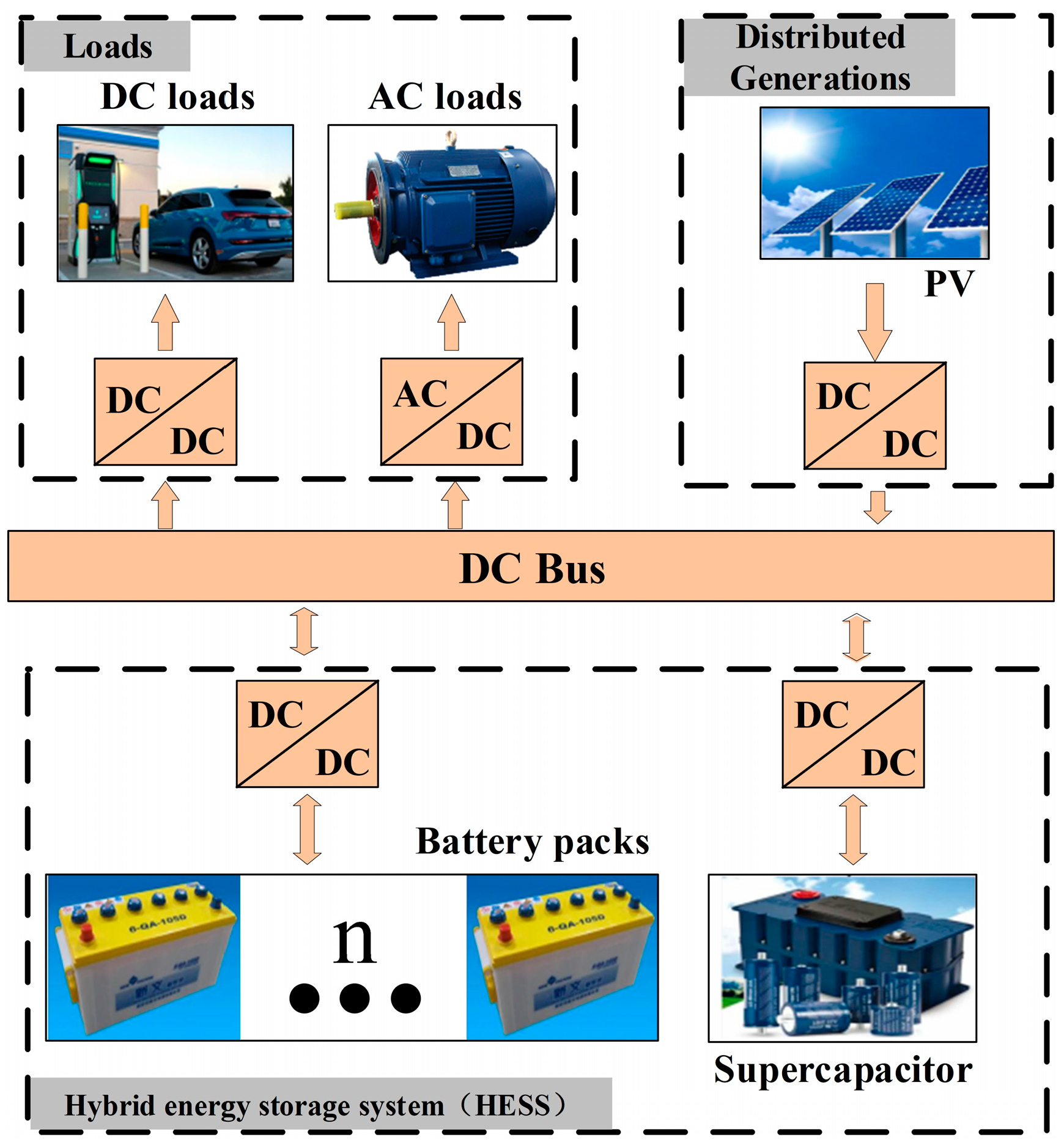
Typical islanded DC microgrids are shown in Figure 1. PV generations, dynamic loads, and large-capacity hybrid energy storage systems (HESS) are all involved. The closed-loop controlled DC/DC converters and DC/AC converters, with cascaded DC and AC loads, are regarded as variable loads. N batteries and cascaded converters are in parallel connections with the supercapacitor and the cascaded converter. The converter controls of HESS intend to suppress power fluctuations of the DC bus and maintain the system stability. The traditional control strategy of the supercapacitor converter is PI double closed-loop control, and the outer power control loop and inner current control loop are both contained. The traditional control strategy of battery converters is also PI double closed-loop control and includes an outer voltage control loop and an inner current control loop.

Figure 1.
Schemes of typical islanded DC microgrids.
2.1. Power Allocation between Different Energy Storage Systems of HESS
Power fluctuations of DC microgrids are always eliminated by HESS. Batteries are utilized to absorb or release low-frequency powers, while the supercapacitor is used to restrain high-frequency powers. Consequently, it is necessary to allocate powers at high and low frequencies, and the low-pass filter becomes a preferred option due to its simplicity and ease of implementation.
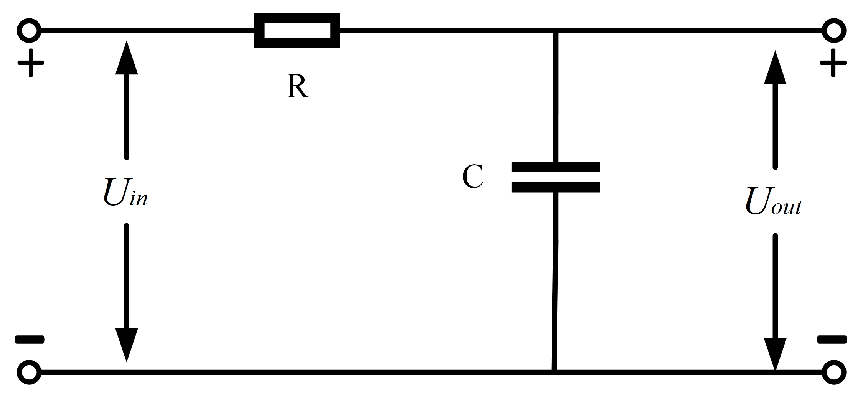
The topology of the first-order low-pass filter is shown in Figure 1. Uin is the input, Uout is the output, and R and C are the filter resistor and capacitor, respectively.
According to Figure 2, the differential equation is obtained and shown as
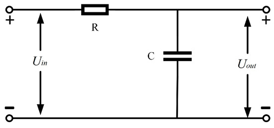
Figure 2.
First-order low-pass filter.
In (1), define T = RC be the filtering time constant, and the transfer function of the low-pass filter is obtained by (1) and shown as
As the time constant T decreases, the passband of the filter becomes wide, and more low-frequency inputs pass through while fewer high-frequency inputs pass through.
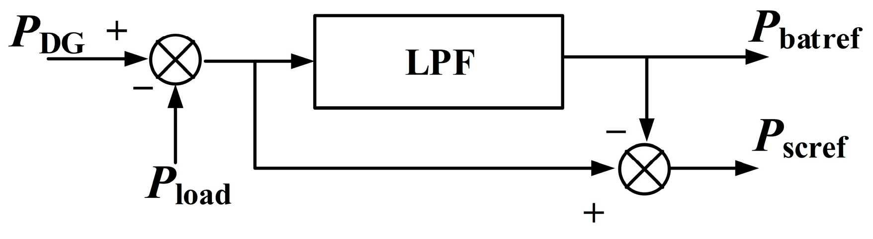
As shown in Figure 3, is the load power, PDG is the distributed supply power, and is the reference battery power, and is the reference supercapacitor power.
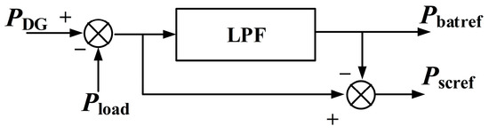
Figure 3.
The principle of the low-pass filter (LPF).
Based on Figure 3, the relationship between powers is obtained and shown as
According to (1) and Equation (2), the reference powers of batteries are obtained as follows:
Similarly, the reference power of the supercapacitor is
The transformation of (5) is
The discretization of (6) leads to
In (7), Tp is the calculation period. Define , and (7) is transformed as
Based on (8), it is obvious that the reference power of the supercapacitor is related to the power of the previous moment, the low-pass filtering time constant T, and the power variation of HESS. Adjusting the filtering time constant T could change power distributions between batteries and the supercapacitor.
2.2. PI Double Closed-Loop Control
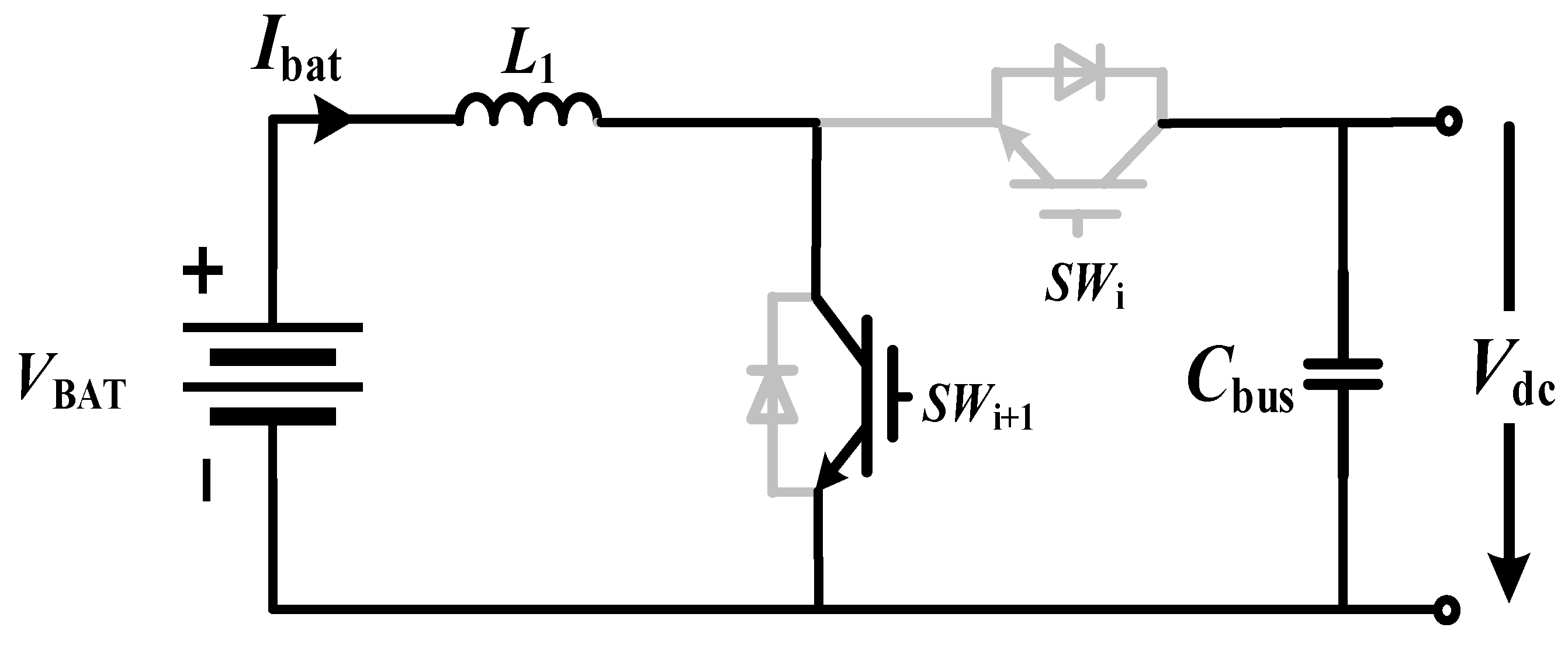
PI double closed-loop control is widely utilized in HESS. DC/DC converters of batteries are chosen as a typical example to illustrate the principle of PI control. The bidirectional DC/DC converter of batteries is shown in Figure 4. is the DC bus voltage, is the DC bus capacitance, and L is the inductor of the battery converter. SW1 and SW2 represent the power switches of the battery converter. The states of the power switches are 0 (off) or 1 (on). D, and are the duty cycle, inductor current, and load current, respectively. Vbat is the battery voltage.
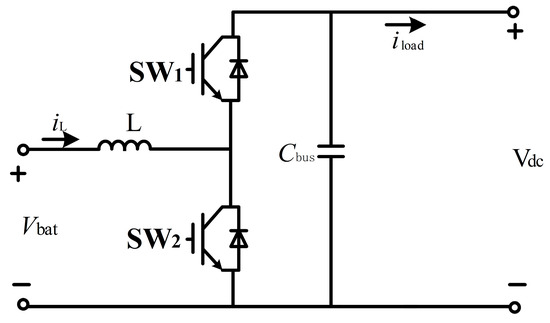
Figure 4.
The topology of the bidirectional Buck–Boost converters in HESS.
Based on Figure 4, state equations are derived and shown as
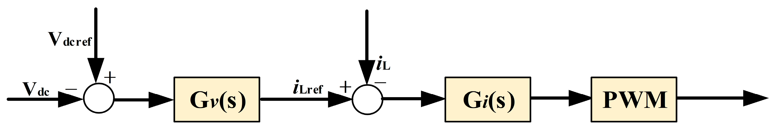
PI double closed-loop control adopted in bidirectional Buck–Boost battery converters is shown in Figure 5. The outer voltage control loop is used to maintain stable DC bus voltage, and the inner current control loop determines the charging or discharging currents of batteries.
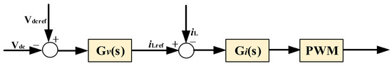
Figure 5.
The block diagram of PI double closed-loop control.
In the depiction presented in Figure 5, the discrepancy between the reference voltage and the DC bus voltage is calculated and subsequently utilized as the input signal for the exterior voltage control loop. The output derived from this outer PI controller serves as the benchmark current for the interior loop. Leveraging the deviation between the reference current and the inductor current, the interior PI controller’s outputs contribute to the generation of PWM signals. The voltage and current controllers’ transfer functions are and with kvi and kvp representing the voltage controller’s integral and proportional coefficients, respectively, while analogous coefficients for the current controller are also specified.
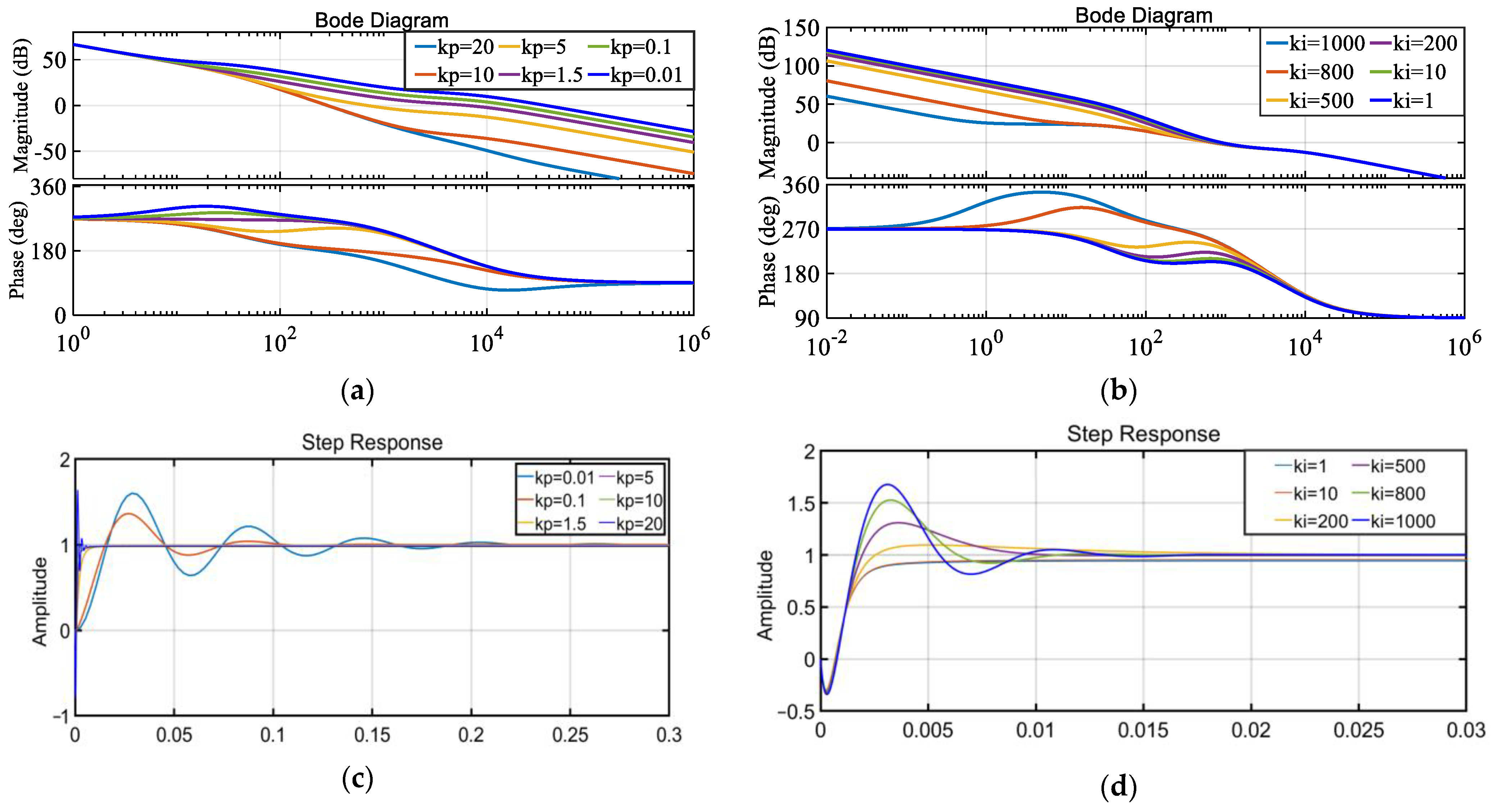
Subsequently, utilizing the voltage control loop’s transfer function, bode plots are constructed and presented in Figure 6a,b. These plots offer insights into the system’s dynamic behavior. Additionally, step response diagrams illustrating the voltage control loop’s performance under varying kp and ki values are shown in Figure 6c and Figure 6d, respectively.
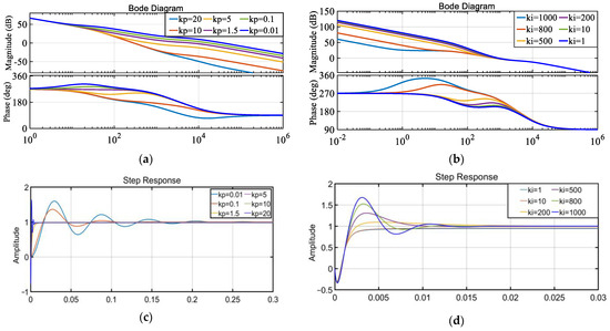
Figure 6.
Bode diagrams and step response diagrams of voltage control loop: (a) Bode diagrams of voltage control loop when kp changes, (b) Bode diagrams of voltage control loop when ki changes. (c) Step response diagrams of voltage control loop when kp changes, (d) Step response diagrams of voltage control loop when ki changes.
To ensure robust stability margins, as evident in Figure 6a,b, the optimal PI parameters for the battery converter’s outer loop are determined to be kvp = 1.5, kvi = 200. These parameters facilitate minimal overshoot and swift regulation, as demonstrated in Figure 6c,d. Furthermore, the battery converter’s inner current loop PI parameters are set to = 45 and = 0.1, respectively.
Analogously, for the supercapacitor converter, the optimal outer-loop PI parameters are identified as = 1 and = 100, while the inner-loop PI parameters are set to = 0.1 and = 20, respectively. These parameter selections aim to optimize the converter’s performance characteristics.
However, the disturbance immunity of traditional PI control is extremely weak, and due to the essential characteristic of PI control, the smallest overshoot and shortest regulation time are not accomplished at the same time. It is essential to introduce a new control strategy to increase response speed, decrease overshoots, and improve immunity to disturbances.
3. Active Disturbance Rejection Control Combined with Improved MPC of Large-Capacity HESS in DC Microgrids
A comprehensive hybrid energy storage system (HESS) incorporates a network of n batteries, each equipped with a dedicated battery converter, alongside a supercapacitor and its corresponding converter. The primary goal of this HESS is to stabilize the DC bus voltage at a constant level. To achieve this, a low-pass filter (LPF) is integrated, which extracts high-frequency power components, serving as a reference input for the supercapacitor converter. To distribute power effectively among the n battery converters and maintain a stable DC bus voltage, droop control is implemented. Additionally, a bus voltage compensator is employed to mitigate any deviations in the DC bus voltage that may arise due to the application of droop control, ensuring optimal system performance.
Aiming at solving problems of weak disturbance immunity and long adjustment time caused by PI control, active disturbance rejection control (ADRC) combined with improved MPC is proposed for HESS. Compared with traditional observers, the voltage expansion state observer of ADRC control is independent of the system model and parameters and consequently has strong disturbance immunity, and significantly reduces voltage overshoots during power fluctuations. Furthermore, the MPC-based inner current control loop accelerates current response speed, and the MPC is improved to achieve smaller switching losses. Based on ADRC, a compensatory approach for DC bus voltage deviations is presented to effectively increase accuracy and maintain constant DC bus voltage.
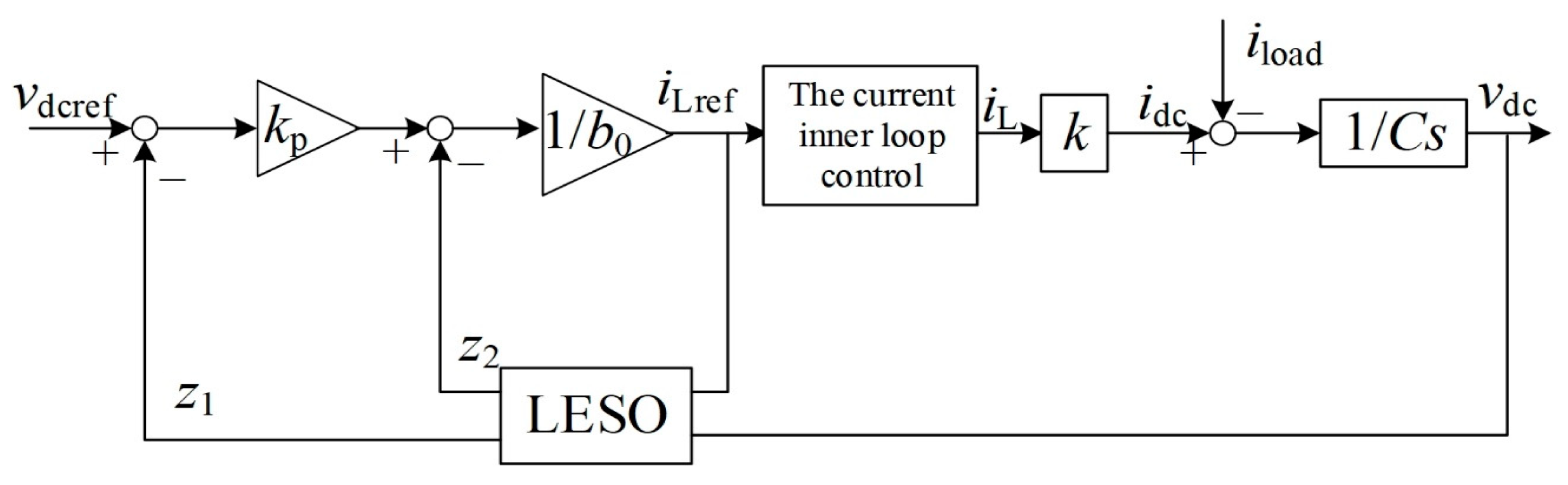
3.1. Active Disturbance Rejection Control of Outer Voltage Control Loop
Based on the bidirectional Buck–Boost converter in Figure 4, supercapacitors have the same topology as batteries. The active disturbance rejection control of the outer voltage control loop is shown in Figure 7. According to power balance, the coefficient . is the current of the inductor, is the current of the converter, and is the load current.
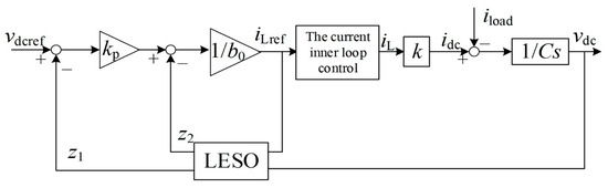
Figure 7.
Active disturbance rejection control of outer voltage loop.
Taking the DC bus voltage and inductor current as state variables, it is derived and shown as
Equation (11) is transformed as
Linearizing (12) around the equilibrium point, it is obtained and shown as
According to (13), it is derived and shown as
In the outer loop, let input , output , and h is a perturbation, then there is a first-order controlled object and shown as
In (15), , , . h is loading current disturbance.
According to , it is obtained and shown as
Then the total perturbations f is expressed as
Both internal and external disturbances are involved in (17), such as disturbances of load current and disturbances of DC bus voltage.
Introducing the state variable , and the expanded state variable , the state space of the controlled object is obtained as follows:
According to (18), the continuous linear expansion state observer is obtained as
In (19), β1 and β2 are the state observer gains. The linearly expanding state observer allows tracking various variables of the controlled object in real time. For the second-order linearly expanding state observer, this ADRC control is simplified by a proportional controller for the system and shown as
Designing state feedback controllers it is
In (21), r is the bus voltage setpoint and is the feedback controller gain.
The Laplace transform for the state observer expression of (18) yields
The collated transformation of (22) yields
Configure 2 poles () of the observer to the left half of the s-plane, and configure the closed-loop poles () to the left half of the s-plane, and determine the configuration equation for the observer gain as follows:
In (24), is the bandwidth of the state observer, is the bandwidth of the controller. These parameters are expressed according to the controller bandwidth and the observer bandwidth and shown as
Combining (21), (23) and (24) yields
Then, it is derived that
The output of the ADRC outer voltage control is obtained, which is the inner-loop current reference value, and shown as
In (28), .
The closed-loop transfer function of the battery converter is derived based on (27) and (28) and shown as
Similarly, the control of the supercapacitor converter simply changes the input value, and its transfer function is:
3.2. Improved Model Predictive Control of the Inner Current Control Loop
Improved model predictive control (MPC) is proposed for the inner current loop of HESS. Based on the prediction of the future state satisfying the state and control constraints, the principle of MPC is to obtain the optimal switching states by minimizing the evaluation function.
The design procedures of MPC are:
- Model the converters and identify all switching modes. Predict behaviors of the controlled variables (e.g., voltages, currents) under various switching modes.
- Define the evaluation function according to the system model and control variables and obtain values of the predicted evaluation function.
- Choose the optimal switching state corresponding to the minimized evaluation function.
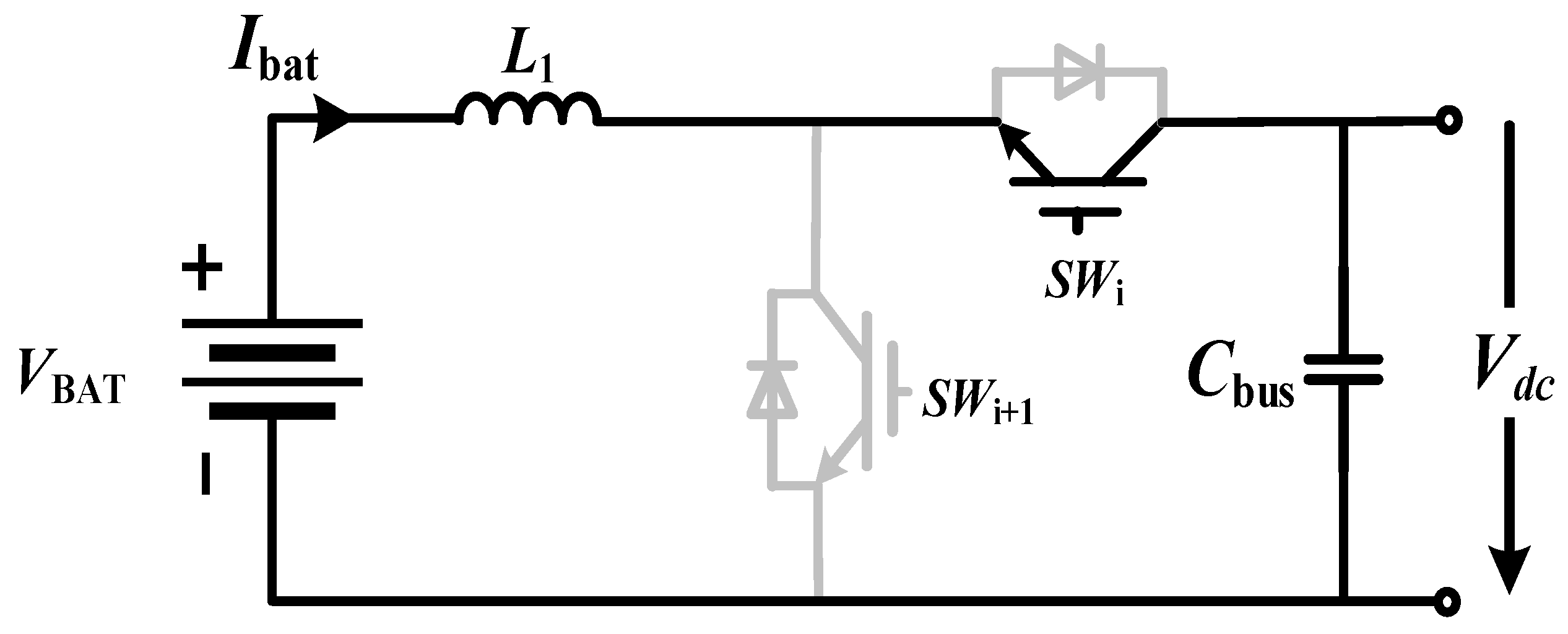
For HESS, the same internal current control strategy is used for battery and supercapacitor converters. Large-capacity HESS composed of n battery converters and a supercapacitor converter is shown in Figure 8. The i-th battery converter is taken as a typical example.
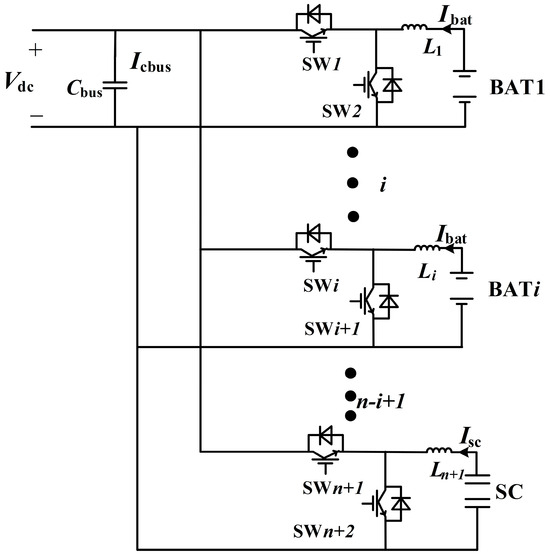
Figure 8.
The topology of large-capacity HESS.
In Figure 8, is the DC bus voltage, is the DC bus capacitance, and is the battery and supercapacitor currents. L1 and Li are the first and i-th inductors of battery converters. Ln+1 is the inductor of supercapacitor converter. SWi, SWi+1, SWn and SWn+1 represent the power switches of i-th battery converter and the supercapacitor converter. The states of the power switches are 0 (off) or 1 (on).
When the conventional MPC is utilized, there are four complementary switching modes for the i-th battery converter and the supercapacitor converter, as shown in Table 1.

Table 1.
Complementary switching modes for HESS when traditional MPC is utilized.
In fact, for HESS Buck–Boost converters, only one power switch action is needed during charging and discharging periods, and the state of the other switch is 0 (off). Unfortunately, the states 0 of 2 switches in the Buck–Boost converter are not considered in Table 1, and complementary switching modes for HESS when traditional MPC is utilized could significantly increase switching losses. Consequently, it is necessary to consider that 2 switches in the Buck–Boost converter are both off, and non-complementary switching modes for HESS when improved MPC is utilized are shown in Table 2.
Table 2.
Non-complementary switching modes for HESS when improved MPC is utilized.
As shown in Table 2, 9 switching modes of battery and supercapacitor converters are divided into 3 types.
Type 1: SWi and SWi+1 is in 1 and 0 states, respectively. The equivalent diagram of the battery converter is shown in Figure 8. Ti is the model-predicted sampling period.
The discharging current is defined as positive, and the mathematical model and the discrete model of the battery converter in Figure 9 are shown as

Figure 9.
Switch states of the battery converter in Type 1.
Type 2: SWi and SWi+1 are 0 and 1, respectively. The equivalent diagram of the battery converter is shown in Figure 10.

Figure 10.
Switch states of the battery converter in Type 2.
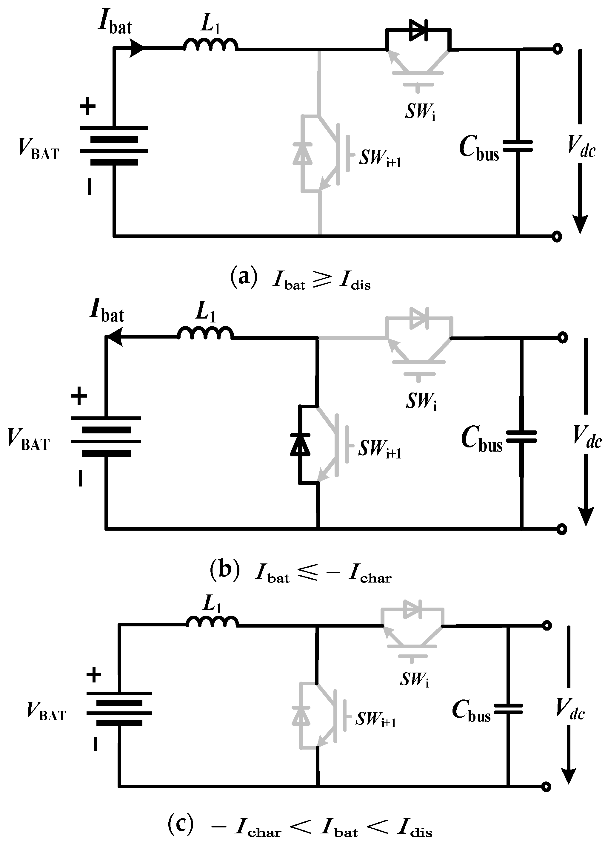
Type 3: SWi and SWi+1 is both 0. The equivalent diagrams of the battery converter involve three cases. As shown in Figure 11, SWi parallel diode is on (a), or the SWi+1 parallel diode is on (b), or all switches are off (c). It is necessary to introduce Idis and Ichar to identify three cases, shown as

Figure 11.
The detailed switch states of the battery converter in Type 3 when Ibat changes.
The mathematical models and discrete models of the battery converter for three cases in Figure 11 are shown as
Similarly, the switching modes of the supercapacitor converter are also divided into three types: 1, 2, and 3. The mathematical models and discrete models are shown as
Consequently, all states of switches are considered, and the evaluation function of the improved MPC is
In (43), n is the number of switches which is on in the next sampling cycle, and are the inner current loop reference values for the battery and the supercapacitor.
The number n of conduction switches is considered in the evaluation function to decrease switching losses.
3.3. Designing a Secondary DC Bus Voltage Compensator in the Condition of Voltage Drops
Droop control is used to achieve power distribution between n batteries, and DC bus voltage deviations are introduced. The accuracy of power distribution is also affected by voltage deviations.
To solve the shortcomings of droop control, a voltage compensator based on active disturbance rejection control (ADRC) is derived. The presented DC bus voltage compensator includes a linear extended state observer and a linear state error feedback control. The linear extended state observer observes and compensates for the total disturbance of the system, the linear state error feedback controller scales the differences between the DC bus reference voltage and the voltage estimated by the linear extended state observer, and finally, the compensated DC bus voltage is obtained based on the high-frequency gain. The controlled object is written as follows:
In (44), , are the input and output of the controlled object. a is the controlled object gain, and b is the controller gain. a and b are unknown, and the assumption b0 is introduced, (44) are written as
Based on linear ADRC, the total disturbance f including internal disturbances and external disturbances is introduced and shown as
Thus, based on (45), (46) is rewritten as
By introducing the state variable and the expanded state variable , the state space of the controlled object is obtained and shown as
The linear expansion state observer is designed as follows:
In (49), β1 and β2 are the state observer gains. The linear ADRC is used to track each variable of the controlled object in real time, and the state feedback controller is designed as follows:
The DC bus voltage deviation after the parameter adjustment is expressed as
In (51), K1, K2 are shown as
3.4. Design Procedure of Proposed Control Strategies of n Parallel Battery Converters and the Supercapacitor Converter in DC Microgrids
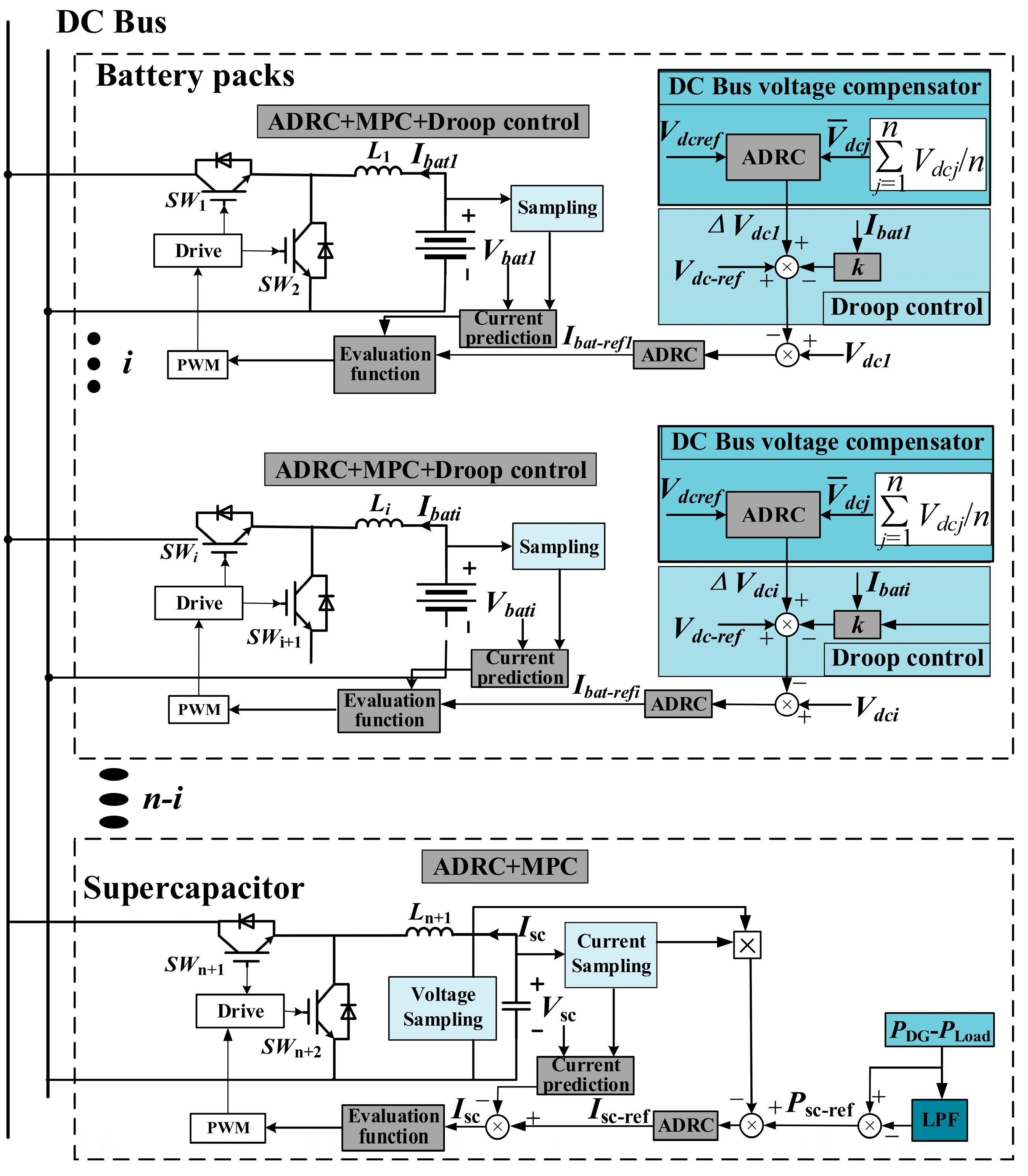
The coordinated control strategy of large-capacity HESS in DC microgrids is shown in Figure 12, and there are n + 1 Buck–Boost converters of HESS. Control strategies of n battery converters are the same. ADRC is utilized in outer voltage control loops, and improved MPC is employed in inner current control loops. Droop control is adopted to obtain power distribution between n battery converters, and the introduced DC bus voltage deviations are compensated for by a DC bus voltage compensator based on a linear ADRC. Compared with traditional observers, the voltage expansion state observer of ADRC control is not related to the system model and parameters, the disturbance immunity is enhanced, and voltage overshoots are significantly reduced. On the other side, in the MPC-based inner current control loop, the current response speed is accelerated and smaller switching losses are achieved.
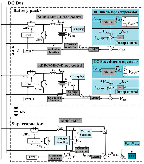
Figure 12.
The active disturbance rejection control (ADRC) combined with improved MPC for large-capacity hybrid energy storage systems in DC microgrids.
The low-pass filter (LPF) is adopted to obtain high-frequency power as the reference for the supercapacitor converter, ADRC is also utilized in the outer power control loop, and MPC is employed in the inner current control loop.
The design procedure of n + 1 bidirectional Buck–Boost converters in HESS is shown as follows.
- (1)
- Based on (7), the reference power of the supercapacitor converter is achieved by a low-pass filter. The reference voltages of n battery converters are all rated DC bus voltage. The total perturbations of the Buck–Boost converter are obtained by (15), and the high-frequency gain b0 of the outer loop is also achieved. Based on the transfer functions in (29) and (30), the outer loop of ADRC is designed, and the reference value of the current inner loop is obtained.
- (2)
- The improved MPC control is modeled, and nine switching modes are enumerated and analyzed to obtain the minimum evaluation function of (43), and the state of all switch disconnects is considered.
- (3)
- By sampling voltages of each battery converter, the average sampling voltage is taken as inputs of ADRC. The compensation voltage is obtained according to (51), and the DC bus voltage remains constant.
4. Simulation Verifications
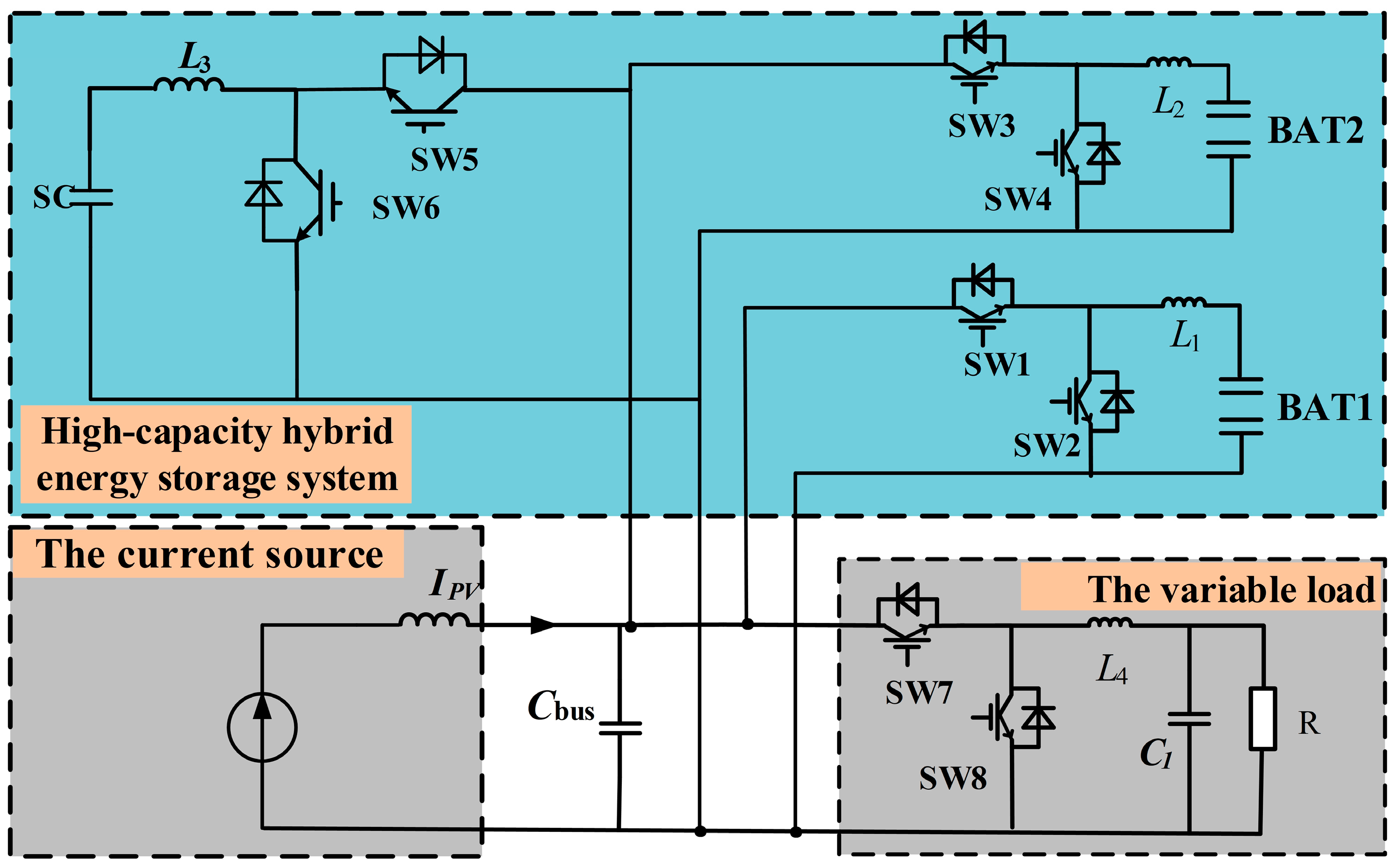
To verify the validity of the proposed control strategies for HESS shown in Figure 12, a simulation model of DC microgrids constituted of HESS is constructed based on Matlab R2020a/Simulink software, and the schematic diagram is shown in Figure 13. The PV generation is represented by a current source with a cascaded boost converter. The variable load is a closed-loop-controlled resistor. HESS involves 2 battery converters and 1 supercapacitor converter. The simulation parameters are shown in Table 3.

Figure 13.
The schematic diagram of DC microgrids constituted 2 battery converters, 1 supercapacitor converter, a current source, and a variable load.
Table 3.
Simulation parameters of DC microgrids constituted of 2 battery converters, 1 supercapacitor converter, a PV generation, and a variable load.
First, the conduction signals of switches are compared when traditional MPC and improved MPC are utilized to verify whether the number of conduction switches is decreased using improved MPC. Second, the characteristic of the proposed DC bus voltage compensator is verified. Finally, the proposed ADRC + improved MPC strategy is compared with the ADRC double closed-loop control strategy and PI double closed-loop control strategy.
The disturbances during simulation are introduced by the power increase of the PV generation and variable load. At 1 s, the PV generation power changes abruptly from 2400 W to 4100 W. At 2 s, the load power varies abruptly from 3100 W to 5000 W and then suddenly drops to 4100 W at 3 s.
4.1. Validations of Improved MPC
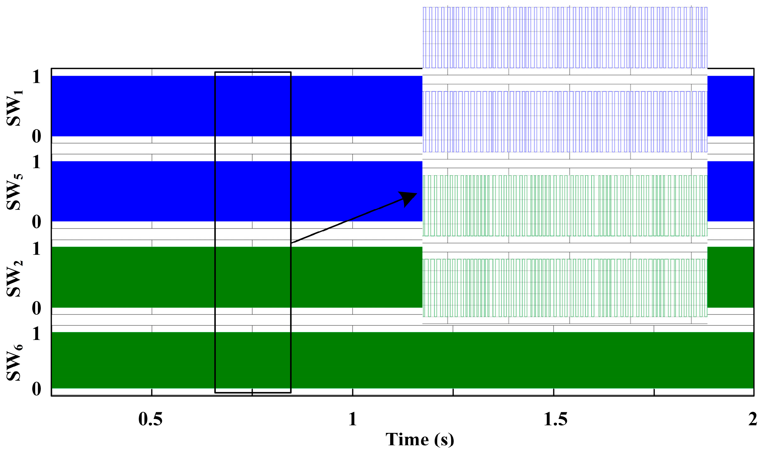
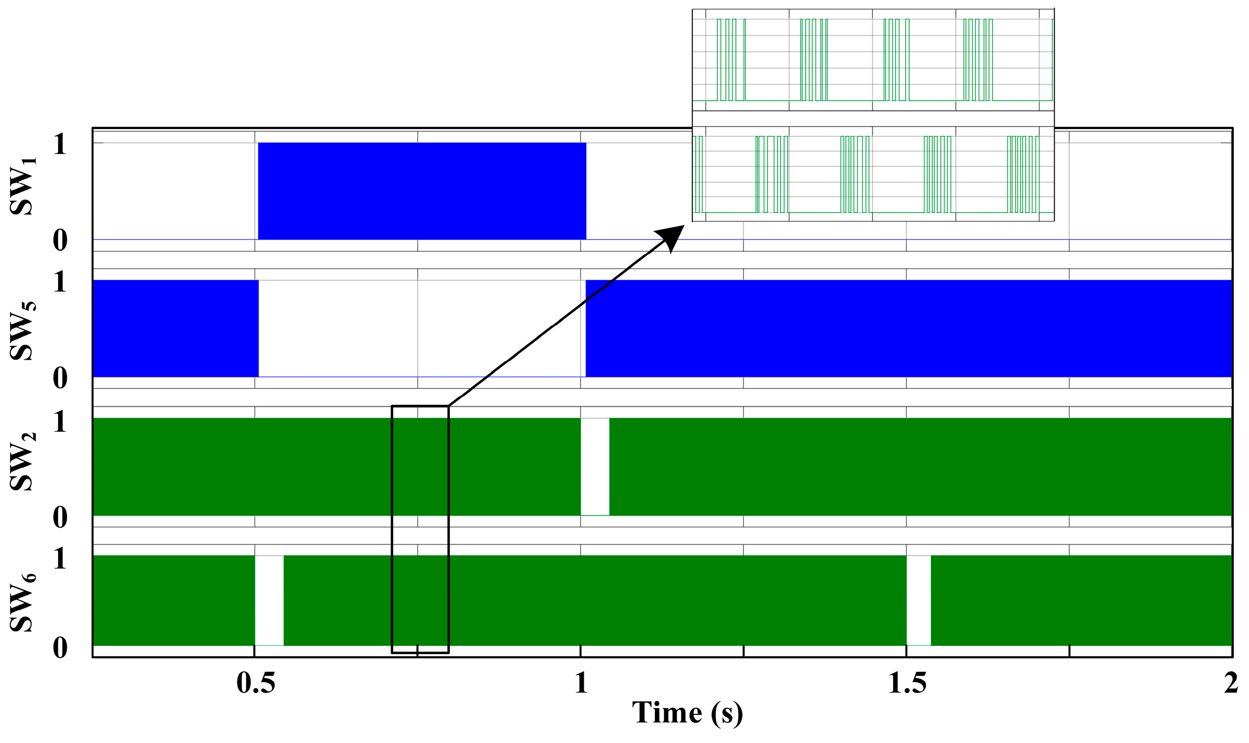
On the same work conditions, the conduction signals SW1 and SW2, SW5 and SW6 are compared when traditional MPC and improved MPC are adopted separately. The conduction signals of 4 switches when traditional MPC is utilized, are shown in Figure 14. The conduction signals of 4 switches, when improved MPC is utilized, are shown in Figure 15. Based on Figure 14 and Figure 15, the number of conduction switches is significantly decreased when improved MPC is used. The performance of improved MPC is excellent, and the unnecessary switching loss is eliminated.
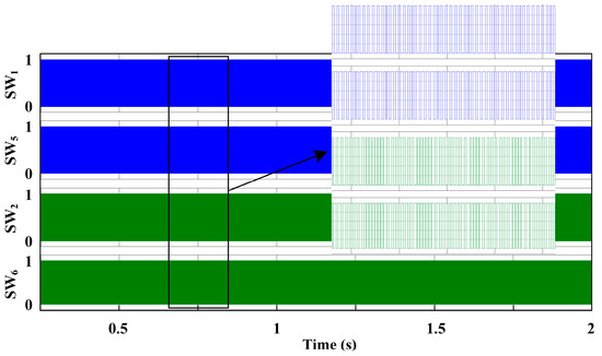
Figure 14.
The conduction signals of switches when traditional MPC is utilized.

Figure 15.
The conduction signals of switches when improved MPC is utilized.
4.2. Simulation Verifications of the Proposed DC Bus Voltage Compensator
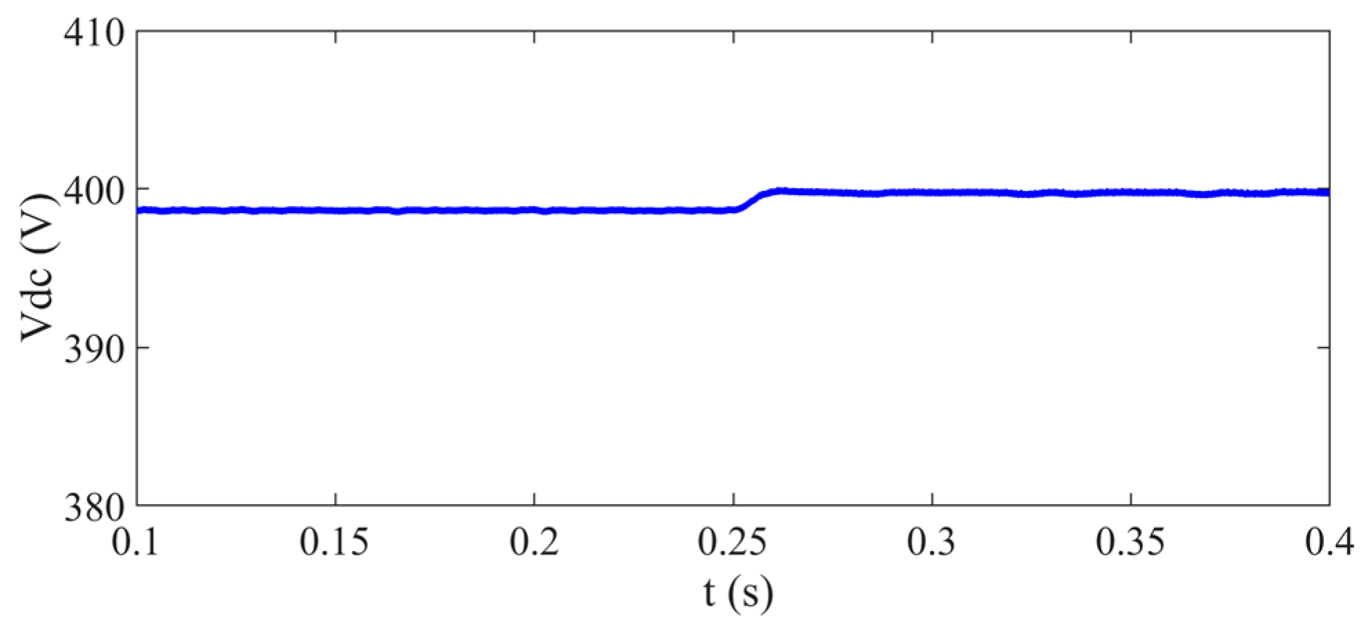
To verify the effectiveness of the derived DC bus voltage compensator, waveforms of DC bus voltage before and after the compensator added at 2 s are shown in Figure 16. Obviously, the DC bus voltage is fixed at the rated voltage of 400 V after 2 s. Consequently, the DC bus voltage drop caused by the droop control is eliminated by the proposed DC bus voltage compensator.
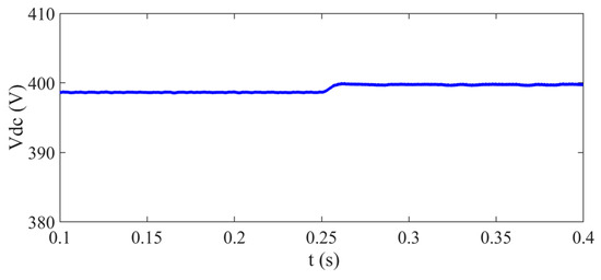
Figure 16.
Waveforms before and after the proposed DC bus voltage compensator are added.
4.3. Validations of ADRC and Improved MPC
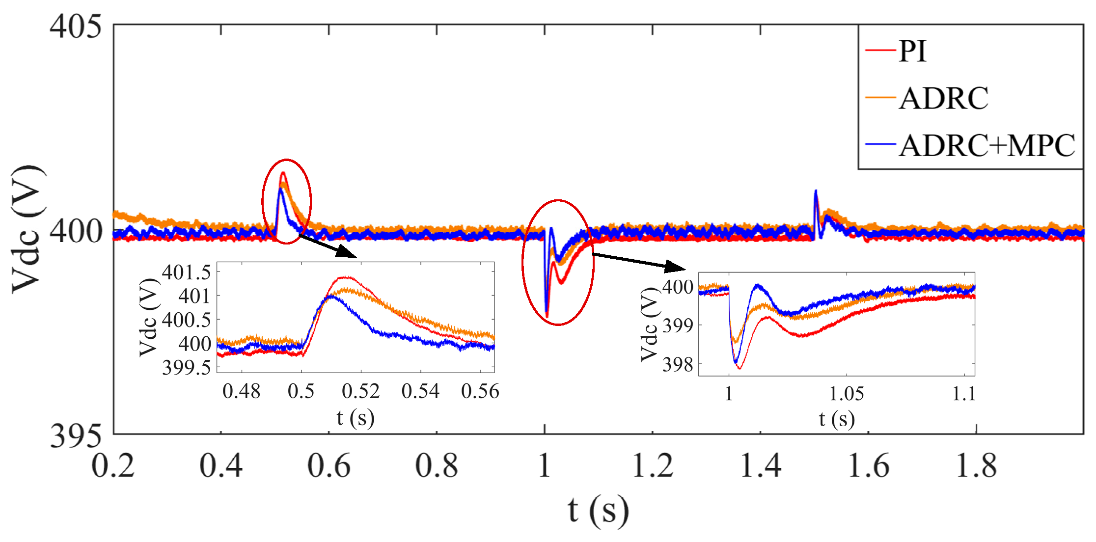
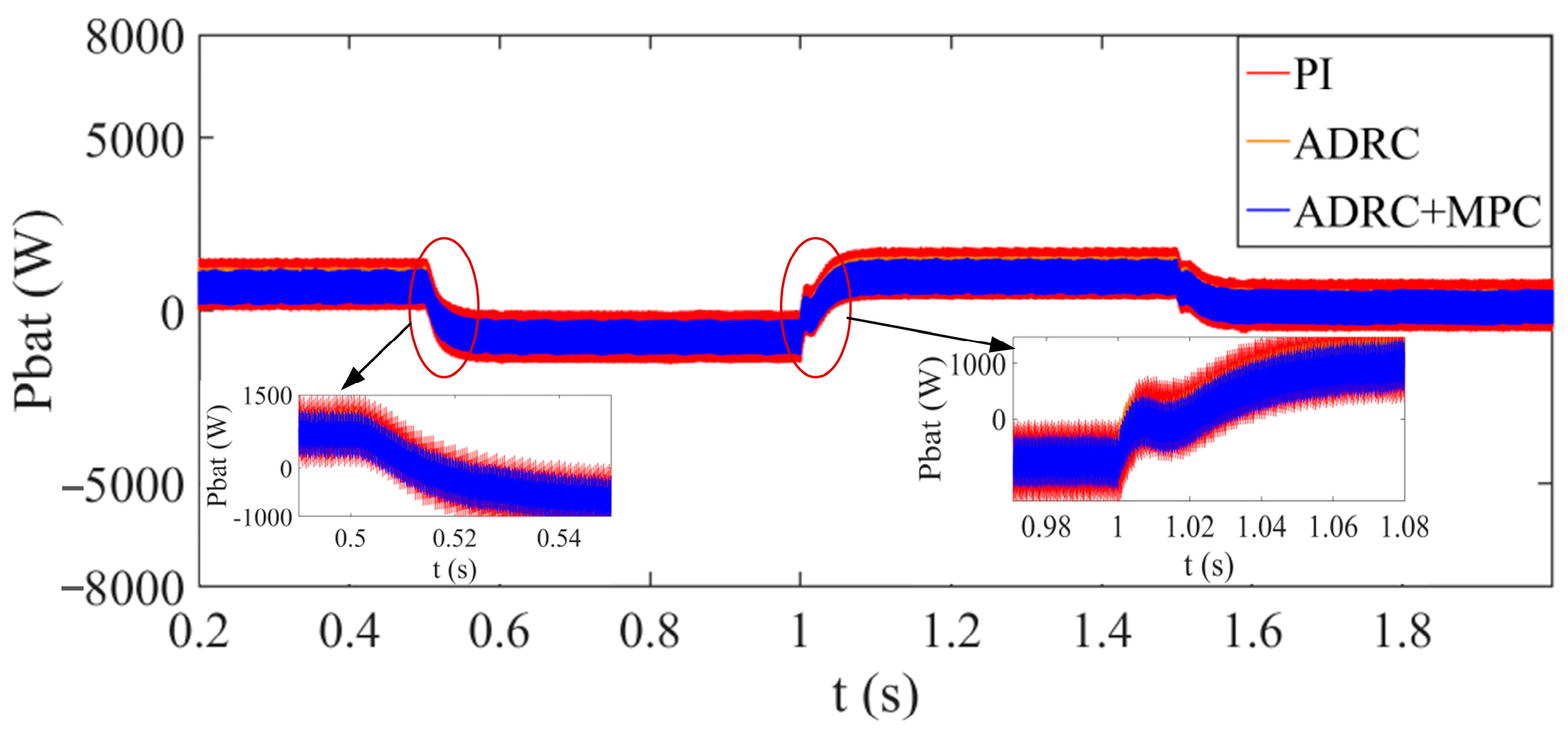
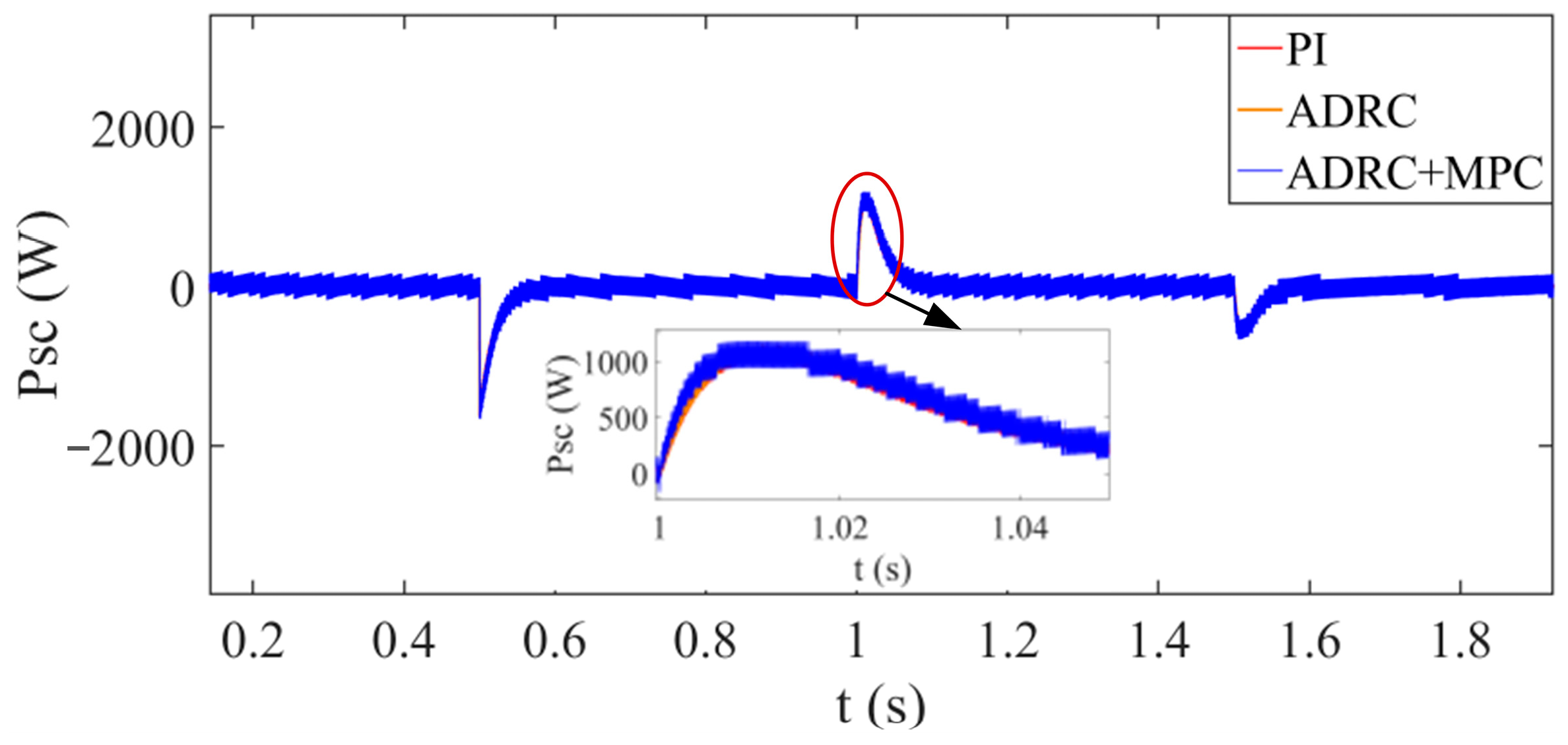
To verify the presented ADRC + improved MPC control strategy, the ADRC double closed-loop control strategy, and the PI double closed-loop control strategy are taken as representatives to achieve comparisons. The PI control parameters use the optimal parameters selected in Figure 6. The waveforms of DC bus voltage, powers of the battery and capacitor when ADRC + improved MPC control strategy, ADRC double closed-loop control strategy, and the PI double closed-loop control strategy are utilized, respectively, are shown in Figure 17, Figure 18 and Figure 19. At 1 s, the power of PV generation decreases from 2400 W to 4100 W, the DC bus voltage overshot of ADRC + MPC is smaller than ADRC and PI, and the recovery time of ADRC + MPC is shorter than the others. Simultaneously, the power fluctuations of the battery and the supercapacitor are also smaller when ADRC + MPC is adopted. At 2 s, the load power increases from 3100 W to 5000 W, and at 3 s, the load power decreases to 4100 W. During these dynamic procedures, the characteristics of the DC bus voltage, the battery power, and the supercapacitor power using ADRC + MPC are superior to these using DRC or PI.
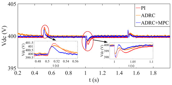
Figure 17.
The waveforms of DC bus voltage when ADRC combined with improved MPC control strategy, ADRC double closed-loop control strategy and the PI double closed-loop control strategy are utilized, respectively.
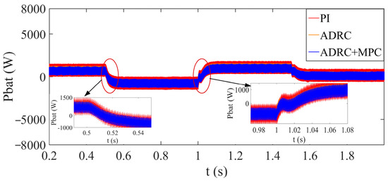
Figure 18.
The powers of the battery when ADRC combined with improved MPC control strategy, ADRC double closed-loop control strategy and the PI double closed-loop control strategy are utilized, respectively.
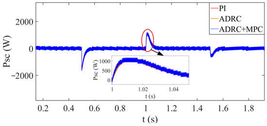
Figure 19.
The powers of the supercapacitor when ADRC combined with improved MPC control strategy, ADRC double closed-loop control strategy, and the PI double closed-loop control strategy are utilized, respectively.
Based on Figure 17, Figure 18 and Figure 19, the proposed ADRC combined with improved MPC for HESS significantly reduces voltage overshoots during disturbances and, consequently, increases the disturbance immunity. The MPC-based inner current control loop accelerates response speed and simultaneously eliminates unnecessary switching losses. The presented DC bus voltage compensator effectively increases the voltage drops and maintains the DC bus voltage constant at the rated value.
The simulation results indicate the excellent dynamic characteristics of ADRC combined with improved MPC.
5. Experimental Results
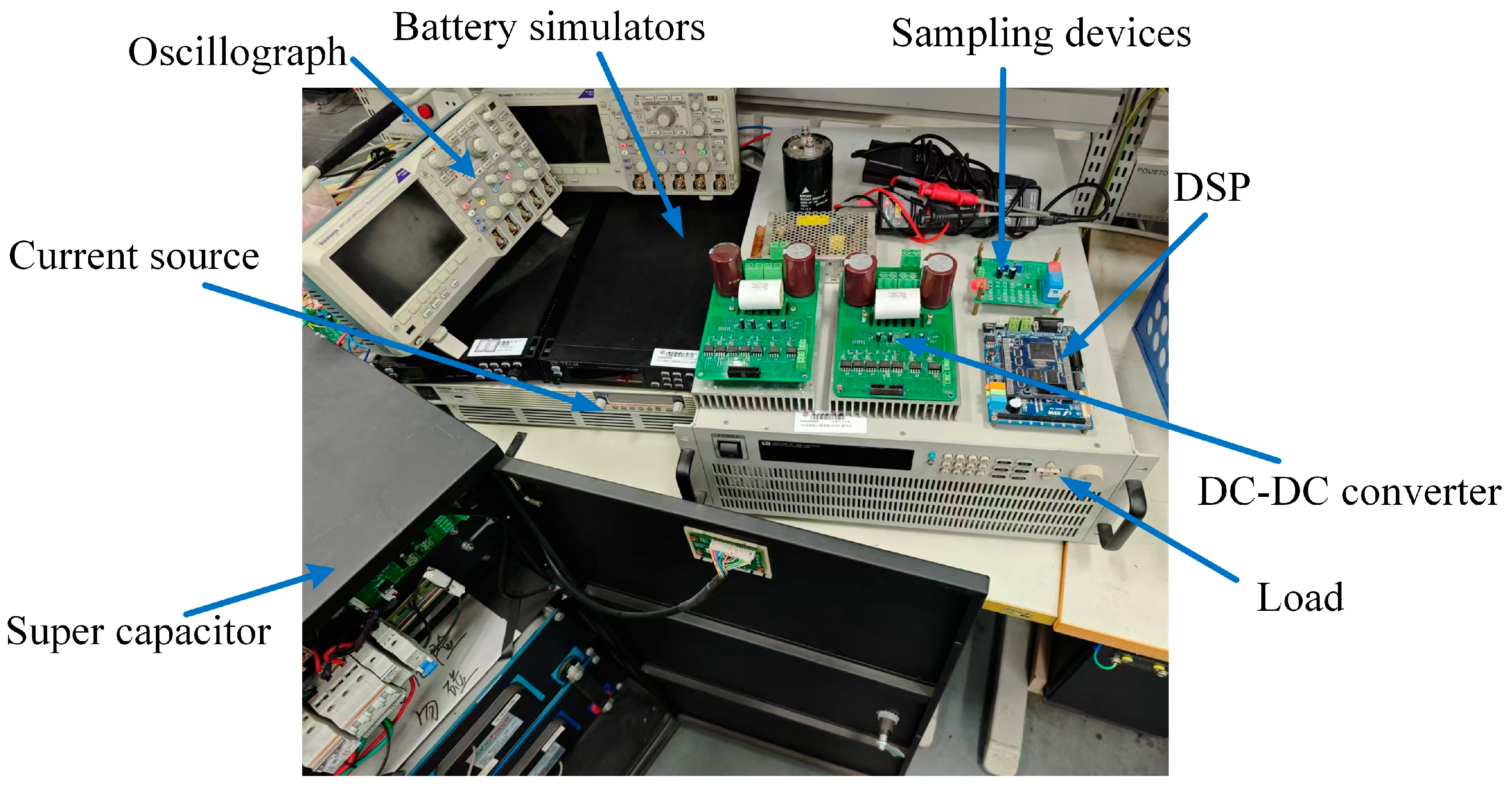
To validate the effectiveness of the proposed ADRC combined with improved MPC of HESS in Figure 12, the experimental platform of DC microgrids is built based on Figure 13 and shown in Figure 20. The parameters of the constructed DC microgrid experimental platform are shown in Table 4. The DC microgrids experimental platform consists of a PV generation, 2 battery converters, 2 battery simulators, 1 supercapacitor converter, the supercapacitor, a resistor, a load converter, 2 oscilloscopes, and auxiliary equipment. The PV generation is represented by a current source. The variable load is a closed-loop-controlled resistor. HESS involves 2 battery converters and 1 supercapacitor converter. The controller adopts DSP-TMS320F28335 produced by Texas Instruments (Dallas, TX, USA).

Figure 20.
The experimental platform of DC microgrids constituted 2 battery converters, 1 supercapacitor converter, a current source, and a variable load.
Table 4.
Experimental platform parameters of DC microgrids.
The bidirectional DC-DC energy storage converters utilize the Intelligent Power Module (IPM) PSS50SA2FT of Mitsubishi-electric (Minato District, Tokyo, Japan)as power devices. The maximum voltage of the programmable DC power supply is 600 V. The batteries are represented by the IT-M3400 bidirectional programmable DC power supply produced by ITECH (Nanjing, China). The supercapacitor is produced by GW Instek company (Suzhou, China), and the rated voltage is 48 V, and the capacity is 166 F. The load is IT8900A/E of ITECH company, and the power range is from 2 kW to 54 kW.
The disturbances of the experiments are introduced by load power variations. The load power decrease is from 80 W to 150 W. The load power increase is from 150 W to 80 W.
First, the effectiveness of the DC bus voltage compensator to compensate for the bus voltage drop is verified during load variations, the waveforms of the DC bus voltage, the load power, the battery currents, and the supercapacitor current of HESS when PI double closed-loop control used without and with voltage compensation are obtained. Second, the characteristics of the proposed ADRC combined with improved MPC are compared with those of PI double closed-loop control.
5.1. Verifications of the Proposed DC Bus Voltage Compensator
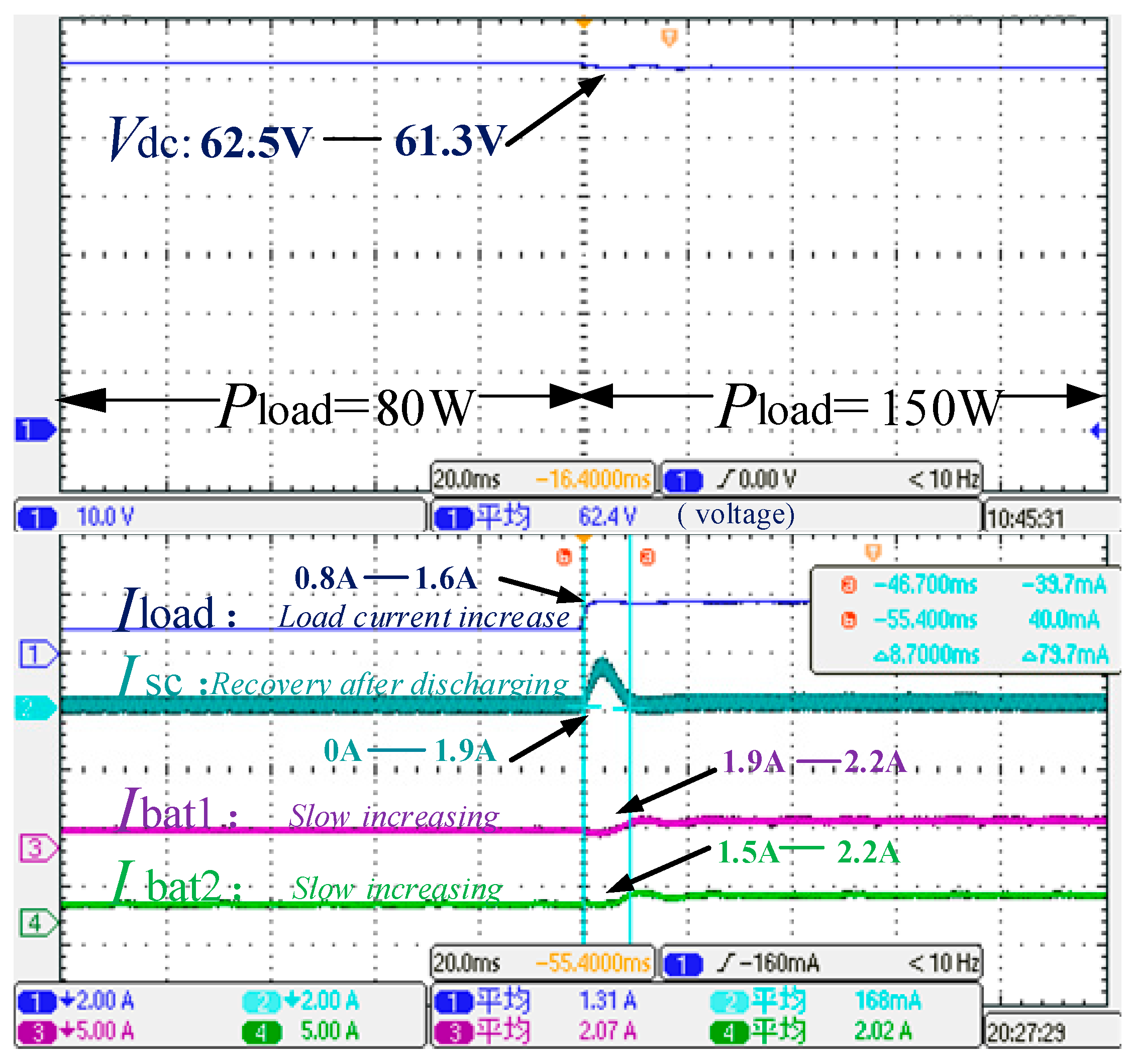
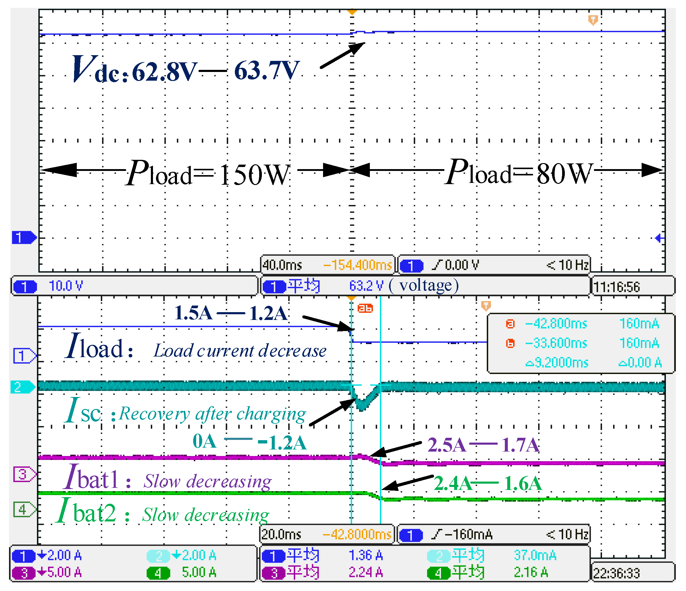
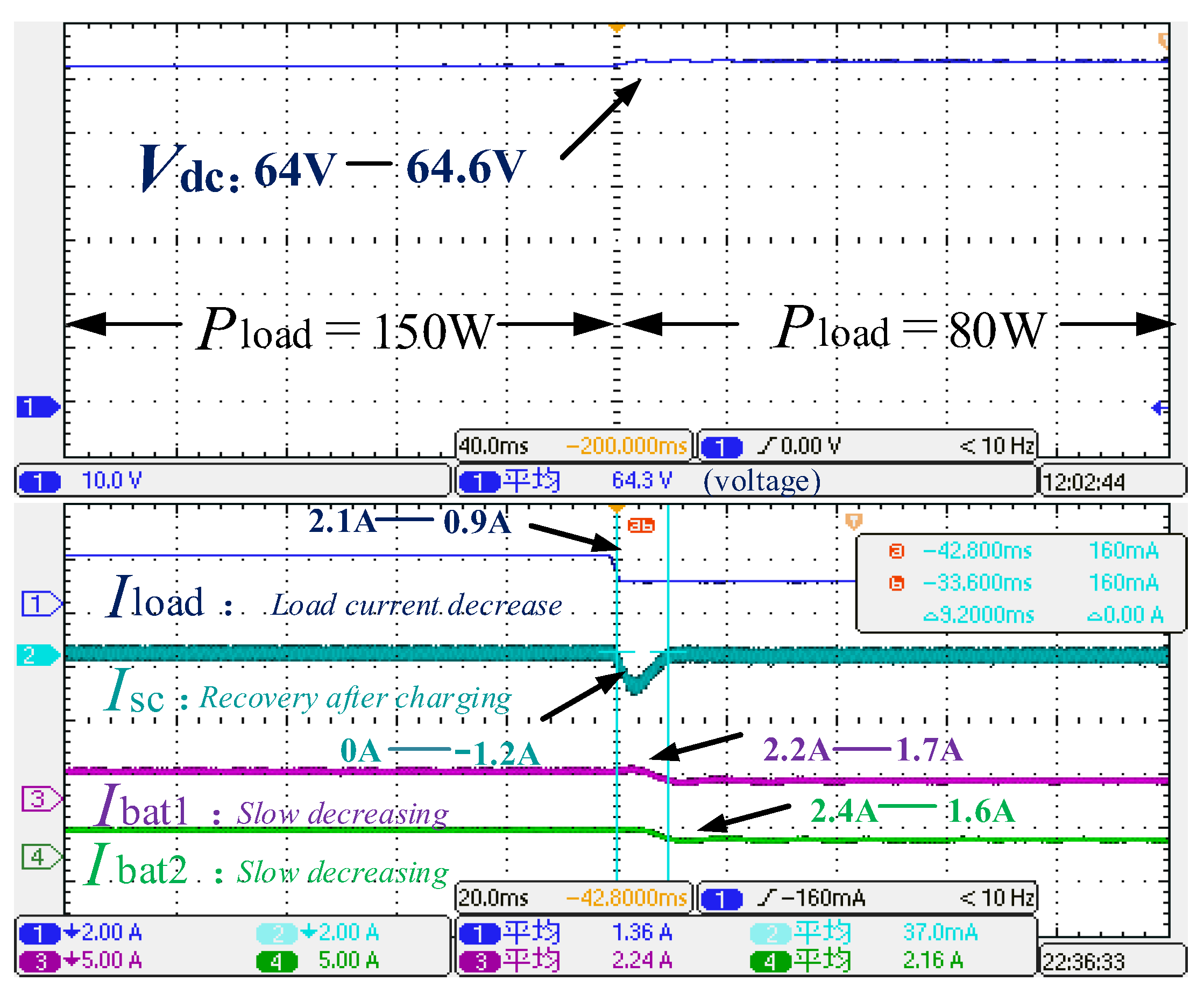
The DC bus voltage, the load power increase, the battery currents, and the supercapacitor current of HESS when the PI double closed-loop control strategy is used without voltage compensation are shown in Figure 21. The signal on the left at the bottom of the oscilloscope result graph represents the voltage and current per grid scale value, and the signal on the right represents the value of the voltage and current. When the load power increases from 80 W to 150 W, the average DC bus voltage is 62.4 V. The DC bus voltage, the load power decrease, the battery currents, and the supercapacitor current of HESS when the PI double closed-loop control strategy is utilized without voltage compensation are shown in Figure 22. When the load power decreases from 150 W to 80 W, the average DC bus voltage is 63.2 V. The DC bus voltage, the load power increase, the battery currents, and the supercapacitor current of HESS when the PI double closed-loop control strategy is used with voltage compensation are shown in Figure 23. When the load power increases from 80 W to 150 W, the average DC bus voltage is 63.4 V. The DC bus voltage, the load power decrease, the battery currents, and the supercapacitor current of HESS when the PI double closed-loop control strategy is adopted with voltage compensation are shown in Figure 24. When the load power decreases from 150 W to 80 W, the average DC bus voltage is 64.6 V.
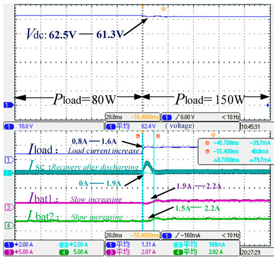
Figure 21.
The DC bus voltage, the load power increase, the battery currents, and the supercapacitor current of HESS when the PI double closed-loop control strategy is used without voltage compensation. The non-English word “平均” in the figure means “average”.

Figure 22.
The DC bus voltage, the load power decrease, the battery currents, and the supercapacitor current of HESS when the PI double closed-loop control strategy is used without voltage compensation. The non-English word “平均” in the figure means “average”.
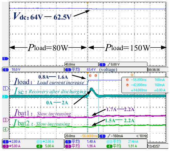
Figure 23.
The DC bus voltage, the load power increase, the battery currents, and the supercapacitor current of HESS when PI double closed-loop control strategy is used with voltage compensation. The non-English word “平均” in the figure means “average”.

Figure 24.
The DC bus voltage, the load power decrease, the battery currents, and the supercapacitor current of HESS when PI double closed-loop control strategy is used with voltage compensation. The non-English word “平均” in the figure means “average”.
Comparing Figure 21 and Figure 23, on condition of the same load power increase (from 80 W to 150 W), the DC bus voltage varies from the original 62.4 V to 63.4 V when DC bus voltage compensation is added. Similarly, comparing Figure 22 and Figure 24, on condition of the same load power decrease (from 150 W to 80 W), the DC bus voltage also increases from primary 63.2 V to 64.6 V using voltage compensation.
The experimental results agree with the simulation results in Figure 16. The verification of proposed DC bus voltage compensator is verified.
5.2. Validations of ADRC Combined with Improved MPC
As shown in Figure 23, when the load power increases from 80 W to 150 W, and the PI double closed-loop control strategy is utilized, the unbalanced power appears. At this moment, the supercapacitor current rapidly increases, suppresses the high-frequency power deficit, and then returns to its original state. The currents of batteries increase slowly to satisfy the increased power demand, and the transient time of HESS is 14 ms. The DC bus voltage amplitude decreases from 64 V to 62.5 V, the voltage drops by 1.5 V, and the output currents of Battery 1 and Battery 2 increase by 0.5 A and 0.7 A, respectively.
In Figure 24, When the load power decreases from 150 W to 80 W, and the PI double closed-loop control strategy is used, the supercapacitor current amplitude rapidly increases and then restores to 0. The battery currents decrease slowly, and the smooth transient time is 13.2 ms. The DC bus voltage amplitude increases from 64 V to 65.4 V, the voltage increases by 1.4 V, and the output currents of Battery 1 and Battery 2 are simultaneously decreased by 1 A.
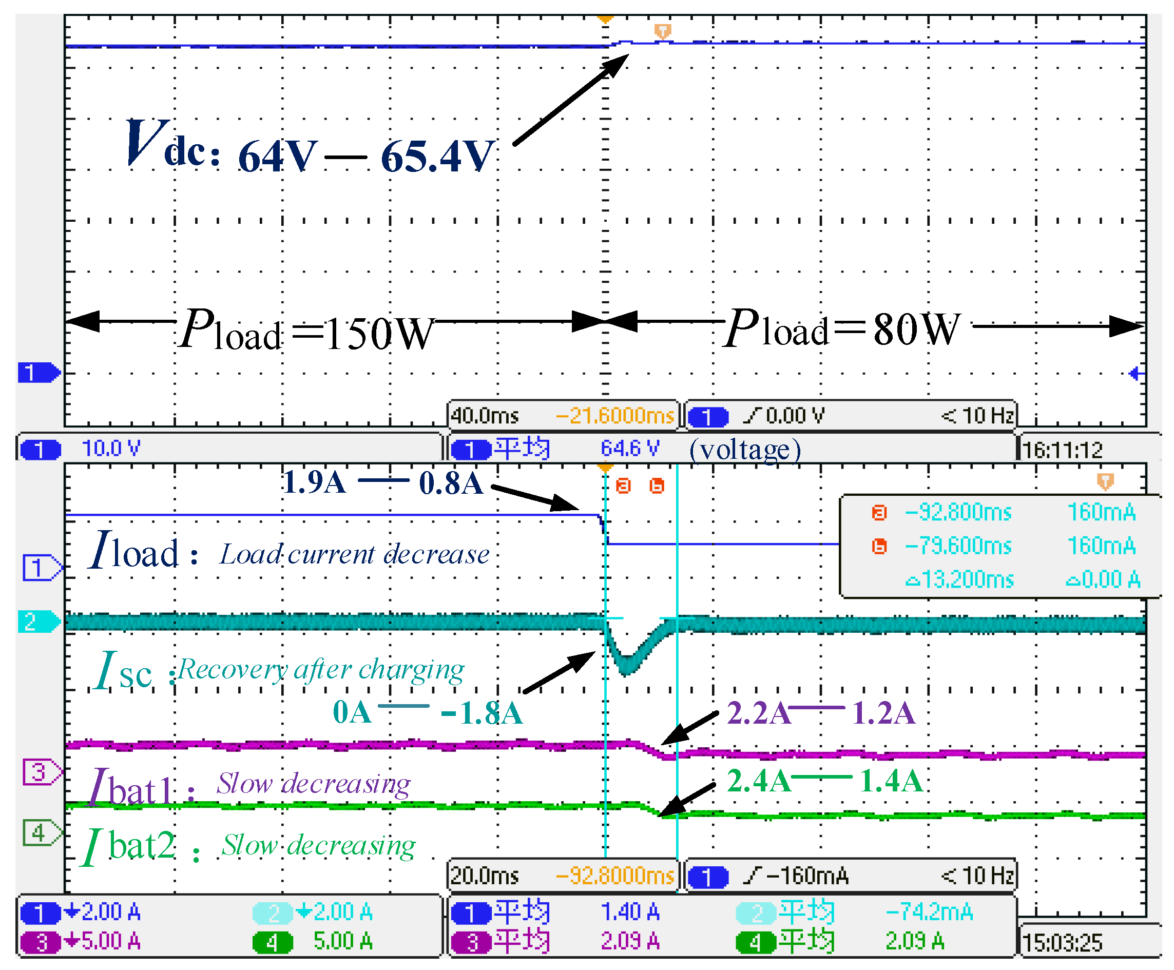
In Figure 25, When the load power increases from 80 W to 150 W and ADRC combined with improved MPC is adopted, the battery currents decrease rapidly, and the smooth transient time is 8.8 ms, the DC bus voltage magnitude decreases from 64 V to 63.6 V, the voltage decreases by 0.4 V, and the output currents of Battery 1 and Battery 2 increase by 0.4 A and 0.6 A, respectively.
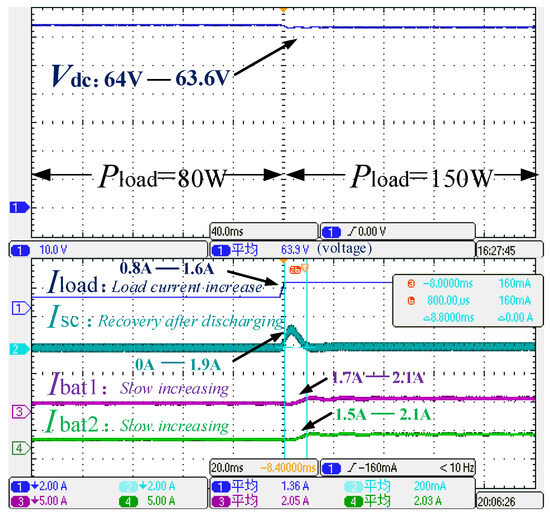
Figure 25.
The DC bus voltage, the load power increase, the battery currents, and the supercapacitor current of HESS when ADRC combined with improved MPC used with voltage compensation. The non-English word “平均” in the figure means “average”.
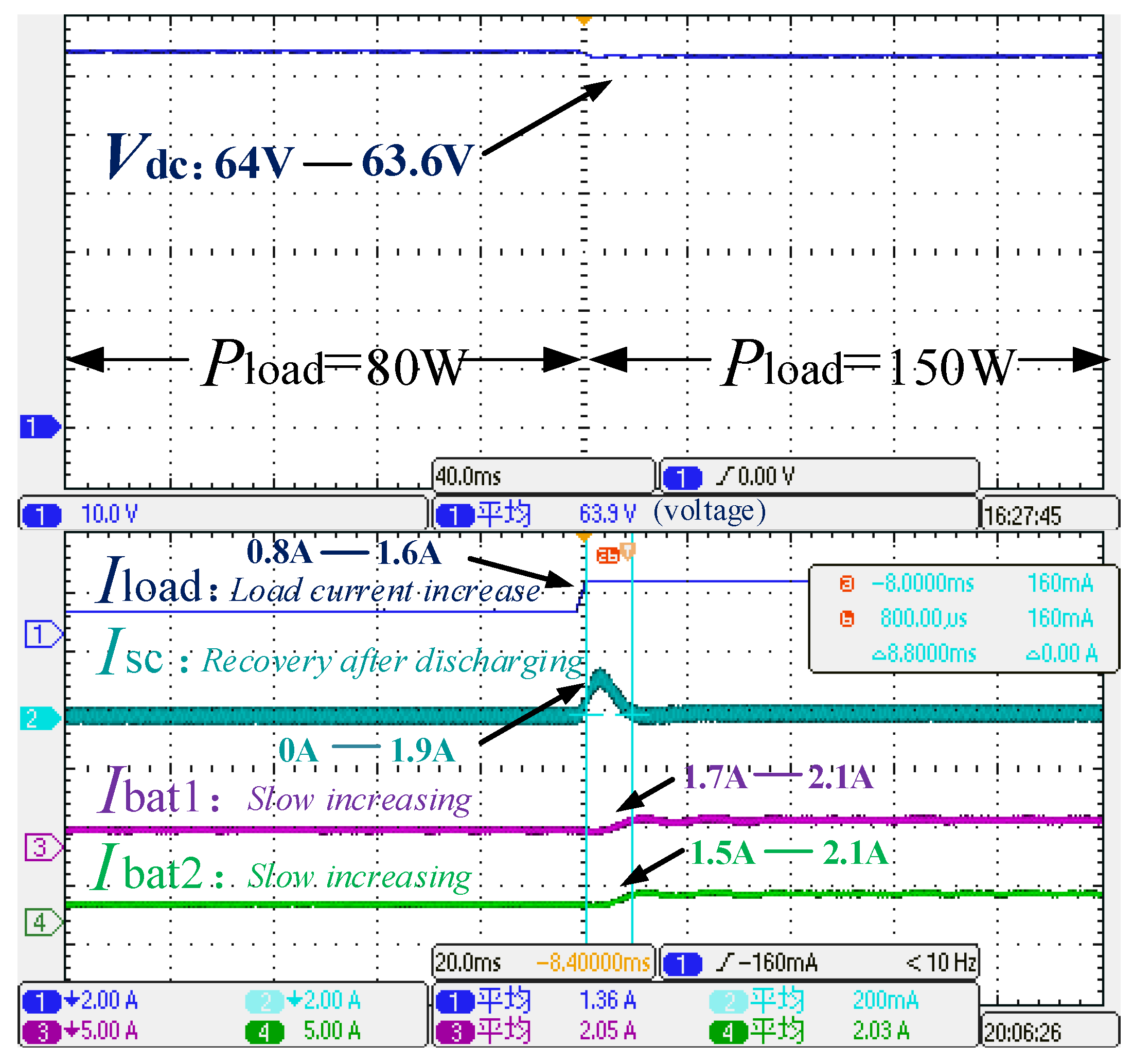
In Figure 26, When the load power decreases from 150 W to 80 W and ADRC combined with improved MPC is utilized, the battery currents decrease rapidly, and the smooth transient time is 9.2 ms, the DC bus voltage amplitude increases from 64 V to 64.6 V, the voltage increases by 0.6 V, and the output currents of the battery 1 and the battery 2 are decreased by 0.5 A and 0.8 A.
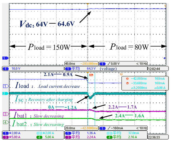
Figure 26.
The DC bus voltage, the load power decrease, the battery currents, and the supercapacitor current of HESS when ADRC combined with improved MPC used with voltage compensation. The non-English word “平均” in the figure means “average”.
Compared to Figure 23 and Figure 25, the voltage step decreases from 1.5 V to 0.4 V; the two battery current steps decrease by 0.1 A, and the system regulation time is reduced from 14 ms to 8.8 ms, and compared to Figure 24 and Figure 26, the voltage step decreases from 1.4 V to 0.6 V; the two battery current steps decrease by 0.5 A and 0.2 A, respectively, and the system regulation time is reduced from 13.2 ms to 9.2 ms.
Based on Figure 23, Figure 24, Figure 25 and Figure 26, it is obvious that using ADRC combined with improved MPC increases the HESS discharging and charging response speed and reduces overshoots of DC bus voltage, compared with PI double closed-loop control.
In summary, experimental results verify the effectiveness of the voltage compensation and the superiority of the proposed ADRC combined with improved MPC.
Both experimental and simulation results show that ADRC, combined with an improved MPC control strategy, could achieve better bus voltage and accelerate the response speed of HESS.
6. Conclusions
First, this paper models the high-capacity hybrid energy storage system in DC microgrids and describes principles of active disturbance rejection control (ADRC) and improved MPC. Second, droop control is adopted to obtain power distribution between n battery converters, and a DC bus voltage compensator based on ADRC is presented to compensate for DC bus voltage deviations. A compensatory approach to eliminating DC bus voltage deviations introduced by droop control is presented, effectively increasing accuracy and maintaining constant DC bus voltage. Then, the design procedures of ADRC in outer voltage control loops and improved MPC in inner current control loops of n battery converters are proposed, and the ADRC combined with MPC for supercapacitor converter is also presented. Compared with traditional observers, the voltage expansion state observer of the proposed ADRC control is independent of the system model and parameters and consequently has strong disturbance immunity and significantly reduces voltage overshoots during power fluctuations. The MPC-based inner current control loop accelerates current response speed and significantly decreases switching losses.
Finally, simulations and experiments are conducted, and comparisons among the proposed ADRC combined with improved MPC, dual PI control, and dual ADRC control are accomplished. The results indicate that the derived control strategies have strong disturbance immunity and significantly reduce voltage overshoots during power fluctuations, accelerate current response speed, and significantly decrease switching losses. ADRC, combined with improved MPC, could greatly improve the service life of power electronic converters and is extremely applicable for large-capacity hybrid energy storage systems.
However, there are some limitations to the proposed control strategy. First, when ADRC is used as the voltage outer loop of HESS, the ADRC parameters may be difficult to choose and there are couplings between parameters. Second, the inner loop adopts the improved MPC to reduce the switching loss, more states of power devices are considered, and complicated calculations are introduced.
Author Contributions
Study design, literature search, and writing the manuscript, X.L.; graph production, data analysis, and data processing, J.C.; supervision and data collection, Y.S.; resources and writing—review and editing, X.S.; translation and literature search, Y.J. All authors have read and agreed to the published version of the manuscript.
Funding
The project is supported by the National Natural Science Foundation of China (52237008) and supported by the Beijing Natural Science Foundation (L243003).
Data Availability Statement
The original contributions presented in the study are included in the article, further inquiries can be directed to the corresponding author.
Conflicts of Interest
The authors declare no conflicts of interest.
References
- Zhang, Q.; Zeng, Y.; Liu, Y.; Zhuang, X.; Zhang, H.; Hu, W.; Guo, H. An improved distributed cooperative control strategy for multiple energy storages parallel in islanded DC microgrid. IEEE J. Emerg. Sel. Top. Power Electron. 2022, 10, 455–468. [Google Scholar] [CrossRef]
- Li, Z.; Wang, B.; Xian, L.; Zhang, M.; Xu, Q. Decentralized Active Disturbance Rejection Control for Hybrid Energy Storage System in DC Microgrid. IEEE Trans. Ind. Electron. 2024, 71, 14232–14243. [Google Scholar] [CrossRef]
- Cui, J.; Tian, G.; Liu, G.; Wu, Y.; Guo, Z. Research on coordinated control strategy of isolated DC microgrid with PV/hybrid energy storage. Energy Rep. 2022, 8 (Suppl. 10), 893–899. [Google Scholar] [CrossRef]
- Zhou, Q.; Jin, J.; Yang, R. Static state power smoothing and transient power quality enhancement of a DC microgrid based on multi-function SMES/battery distributed hybrid energy storage system. Energy Rep. 2022, 8 (Suppl. 13), 44–51. [Google Scholar] [CrossRef]
- Zheng, Z.; Chen, X.; Hu, W.; Wang, Y.; Zong, Y.; Huang, C.; Ni, F. Dual Model Predictive Controlled Hybrid Energy Storage System for Naval DC Microgrids. IEEE Trans. Transp. Electrif. 2023, 9, 156–168. [Google Scholar] [CrossRef]
- Liu, X.; Suo, Y.; Song, X.; Zhou, J.; Qu, Y. Large-Signal Stabilization Method for Islanded DC Microgrids Considering Battery and Supercapacitor Hybrid Energy Storage Systems. Electronics 2022, 11, 2823. [Google Scholar] [CrossRef]
- Mitra, S.K.; Karanki, S.B. An SOC Based Adaptive Energy Management System for Hybrid Energy Storage System Integration to DC Grid. IEEE Trans. Ind. Appl. 2023, 59, 1152–1161. [Google Scholar] [CrossRef]
- Liu, X.; Suo, Y.; Zhang, Z.; Song, X.; Zhou, J. A New Model Predictive Current Control Strategy for Hybrid Energy Storage System Considering the SOC of the Supercapacitor. IEEE J. Emerg. Sel. Top. Power Electron. 2023, 11, 325–338. [Google Scholar] [CrossRef]
- Zhao, X.; Zhang, Y.; Cui, X.; Wan, L.; Qiu, J.; Shang, E.; Zhang, Y.; Zhao, H. Wavelet Packet-Fuzzy Optimization Control Strategy of Hybrid Energy Storage Considering Charge–Discharge Time Sequence. Sustainability 2023, 15, 10412. [Google Scholar] [CrossRef]
- Xiang, C.; Cheng, Q.; Zhu, Y.; Zhao, H. Sliding Mode Control of Ship DC Microgrid Based on an Improved Reaching Law. Energies 2023, 16, 1051. [Google Scholar] [CrossRef]
- Ahmed, K.; Hussain, I.; Seyedmahmoudian, M.; Stojcevski, A.; Mekhilef, S. Voltage Stability and Power Sharing Control of Distributed Generation Units in DC Microgrids. Energies 2023, 16, 7038. [Google Scholar] [CrossRef]
- Elnady, A.; Noureldin, A.; Adam, A.A. Improved Synergetic Current Control for Grid-connected Microgrids and Distributed Generation Systems. J. Mod. Power Syst. Clean Energy 2022, 10, 1302–1313. [Google Scholar] [CrossRef]
- Bonfiglio, A.; Procopio, R.; Rosini, A.; Incremona, G.P.; Ferrara, A. A Comprehensive Sliding Mode Approach for Photovoltaic-Storage Islanded Microgrids. In Proceedings of the 2023 IEEE Belgrade PowerTech, Belgrade, Serbia, 25–29 June 2023; pp. 1–5. [Google Scholar]
- Al Sumarmad, K.A.; Sulaiman, N.; Wahab, N.I.A.; Hizam, H. Energy Management and Voltage Control in Microgrids Using Artificial Neural Networks, PID, and Fuzzy Logic Controllers. Energies 2022, 15, 303. [Google Scholar] [CrossRef]
- Yuan, L.; Xiu, C.; Ma, X. Sliding mode control strategy for microgrid inverter systems. J. Power Electron. 2023, 23, 821–831. [Google Scholar] [CrossRef]
- Zhang, M.; Xu, Q.; Zhang, C.; Nordström, L.; Blaabjerg, F. Decentralized Coordination and Stabilization of Hybrid Energy Storage Systems in DC Microgrids. IEEE Trans. Smart Grid 2022, 13, 1751–1761. [Google Scholar] [CrossRef]
- Kim, S.-K.; Park, C.R.; Kim, J.-S.; Lee, Y.I. A stabilizing model predictive controller for voltage regulation of a DC/DC boost converter. IEEE Trans. Control. Syst. Technol. 2014, 22, 2016–2023. [Google Scholar] [CrossRef]
- Qiu, C.; Li, Z.; Tan, Q.; Huang, J.; Wang, D. Hybrid Model Linearization Predictive Control for DC Bus Stabilization in Spacecraft Combined Power System. IEEE J. Emerg. Sel. Top. Power Electron. 2022, 10, 5345–5356. [Google Scholar] [CrossRef]
- Peng, W.; Chen, Q.; Manandhar, U.; Wang, B.; Rodriguez, J. Event-Triggered Model Predictive Control for the Inverter of a Grid-Connected Microgrid With a Battery-Supercapacitor HESS. IEEE J. Emerg. Sel. Top. Power Electron. 2023, 11, 5540–5552. [Google Scholar] [CrossRef]
- Tian, M.; Wang, B.; Yu, Y.; Dong, Q.; Xu, D. Adaptive Active Disturbance Rejection Control for Uncertain Current Ripples Suppression of PMSM Drives. IEEE Trans. Ind. Electron. 2024, 71, 2320–2331. [Google Scholar] [CrossRef]
- Du, Y.; Cao, W.; She, J. Analysis and Design of Active Disturbance Rejection Control With an Improved Extended State Observer for Systems With Measurement Noise. IEEE Trans. Ind. Electron. 2023, 70, 855–865. [Google Scholar] [CrossRef]
- Long, B.; Zeng, W.; Rodríguez, J.; Garcia, C.; Guerrero, J.M.; Chong, K.T. Stability Enhancement of Battery-Testing DC Microgrid: An ADRC-Based Virtual Inertia Control Approach. IEEE Trans. Smart Grid 2022, 13, 4256–4268. [Google Scholar] [CrossRef]
- Shan, Z.; Wang, Y.; Liu, X.; Wei, C. Fuzzy Automatic Disturbance Rejection Control of Quadrotor UAV Based on Improved Whale Optimization Algorithm. IEEE Access 2023, 11, 69117–69130. [Google Scholar] [CrossRef]
- Tao, L.; Wang, P.; Wang, Y.; Ma, X.; Shi, H.; Yang, S. Automatic-Optimization ADRC-Based Disturbance Rejection Method for Low Voltage Interface Converter in Microgrid. In Proceedings of the 2022 IEEE Energy Conversion Congress and Exposition (ECCE), Detroit, MI, USA, 9–13 October 2022; pp. 1–6. [Google Scholar]
- Dai, T.; Mao, J.; Ding, Y.; Yin, C.; Zhang, X. Bus voltage stability control of the distributed photovoltaic and energy storage DC microgrid based on ADRC. In Proceedings of the 2021 IEEE International Conference on Recent Advances in Systems Science and Engineering (RASSE), Shanghai, China, 12–14 December 2021; pp. 1–7. [Google Scholar]
- Hai, T.; Liu, Y.; Wang, J.; Lu, J. Control Strategy of Photovoltaic Hybrid Energy Storage System Based on Model Predictive Control. J. Power Supply 2024, 1–12. [Google Scholar]
- Nguyen, H.D.; Tran, L.T.H.; Nguyen, T.D.; Pham, M.D. Load Profile-Based Setpoint Design for Piecewise Droop Controller to Mitigate Current Sharing Error in Dual Active Bridge System. IEEJ Trans. Electr. Electron. Eng. 2024, 19. [Google Scholar] [CrossRef]
- Chang, S.; Wang, C.; Luo, X.; Guan, X. Distributed predefined-time secondary control under directed networks for DC microgrids. Appl. Energy 2024, 374, 123993. [Google Scholar] [CrossRef]
- Li, X.; Wang, M.; Jiang, W.; Dong, C.; Xu, Z.; Wu, X. An Autonomous Finite-Time Backstepping Control for Decentralized Automatic Power Sharing of Hybrid Energy Storage Systems in DC Microgrids. IEEE Trans. Smart Grid 2024, 15, 3348–3360. [Google Scholar] [CrossRef]
- Lasabi, O.; Swanson, A.; Jarvis, L.; Aluko, A.; Brown, M. Enhanced Distributed Non-Linear Voltage Regulation and Power Apportion Technique for an Islanded DC Microgrid. Appl. Sci. 2023, 13, 8659. [Google Scholar] [CrossRef]
- Xing, L.; Qi, Y.; Liu, X.-K.; Wen, C.; Liu, M.; Tian, Y.-C. Discrete-Time Distributed Secondary Control for DC Microgrids via Virtual Voltage Drop Averaging. IEEE Trans. Sustain. Energy 2023, 14, 272–282. [Google Scholar] [CrossRef]
- Zeng, Y.; Zhang, Q.; Liu, Y.; Zhuang, X.; Guo, H. Hierarchical Cooperative Control Strategy for Battery Storage System in Islanded DC Microgrid. IEEE Trans. Power Syst. 2022, 37, 4028–4039. [Google Scholar] [CrossRef]
- Zhuo, S.; Ma, Y.; Liu, X.; Zhang, R.; Jin, S.; Huangfu, Y. Quasi-Resonant-Based ADRC for Bus Voltage Regulation of Hybrid Fuel Cell System. IEEE Trans. Ind. Electron. 2024, 1–10. [Google Scholar] [CrossRef]
- Li, J.; You, H.; Liu, S.; Li, X.; Ding, Z.; Zou, F. Active disturbance rejection distributed secondary control for DC microgrids. High Volt. 2024, 9, 241–251. [Google Scholar] [CrossRef]


Disclaimer/Publisher’s Note: The statements, opinions and data contained in all publications are solely those of the individual author(s) and contributor(s) and not of MDPI and/or the editor(s). MDPI and/or the editor(s) disclaim responsibility for any injury to people or property resulting from any ideas, methods, instructions or products referred to in the content. |
© 2024 by the authors. Licensee MDPI, Basel, Switzerland. This article is an open access article distributed under the terms and conditions of the Creative Commons Attribution (CC BY) license (https://creativecommons.org/licenses/by/4.0/).