Communication

Design of a Feed Array Antenna to Obtain a Uniform Near-Field Distribution on a Virtual Surface Placed within a Specified Wavelength

1
Department of Electronic and Electrical Engineering, Hongik University, Seoul 04066, Republic of Korea
2
Hanwha Systems Company Ltd., Yongin 17121, Republic of Korea
*
Author to whom correspondence should be addressed.
Appl. Sci. 2024, 14(19), 8632; https://doi.org/10.3390/app14198632
Submission received: 23 July 2024 / Revised: 17 September 2024 / Accepted: 17 September 2024 / Published: 25 September 2024

Abstract

:
This paper proposes a novel feed array antenna to achieve a uniform electric field distribution in the near-field region for feeding a large-aperture antenna. The feed antenna has a 4 × 4 rectangular array configuration to obtain uniform near-field distribution on a virtual target surface. Each element of the array consists of a Vivaldi radiator and parasitic rings, and these two components have different radiating modes. In particular, the near-field pattern of the parasitic rings can be varied by adjusting their radii. Thus, the required near-field distribution on the virtual target surface can be achieved by optimizing the radii of the parasitic rings. To further enhance the uniformity of the electric field, the input phase of each Vivaldi radiator is adjusted by applying different transmission line lengths to the Vivaldi radiators depending on their positions in the array. To verify the feasibility of the proposed antenna, the electric field distributions are measured in an electromagnetic anechoic chamber. The results demonstrate that the proposed feed array antenna can achieve uniform near-field distribution with an average of 1.7 dB and a deviation of 6.8 dB on the virtual target surface placed within half a wavelength from the antenna aperture.

1. Introduction

Feed antennas are typically employed to operate various electrical large-aperture antennas, such as dielectric lens antennas, frequency selective surfaces, and metasurface transmissive arrays [1,2,3,4,5,6,7,8,9]. The feed antennas make it possible to generate a desired electric field distribution over the surface of a large-aperture antenna, enabling a high gain and beam steering while maintaining low design complexity and manufacturing costs [10,11,12]. In general, patch antennas [13], horn antennas [14], and log-periodic dipole antennas [15] are used as feed antennas. However, these feed antennas are often mounted in the far-field region several wavelengths away from a large-aperture surface, which poses the problem of increasing the overall volume of the antenna system. To resolve this problem, research has been conducted on near-field feed antennas that can be placed within a specific wavelength from the large-aperture antenna [16,17]. In the near-field region, since it is difficult to generate a uniform electric field distribution using a single-element feed antenna, studies on array feed antennas including multiple elements have recently been conducted [18,19,20]. In particular, array feed antennas are competitive for near-field feeding because they can adjust the amplitude and phase of each element to achieve more uniform field generation in the near-field region.
In this paper, we propose a novel feed array antenna to achieve a uniform electric field distribution in the near-field region for feeding a large-aperture antenna. The feed antenna has a 4 × 4 rectangular array configuration to obtain uniform near-field distribution on a virtual target surface. The virtual target surface was set as a flat surface with dimensions of 200 × 200 mm2. The size of the virtual surface can be flexibly determined to suit the requirements of the specific application. Each element of the array consists of a Vivaldi radiator and parasitic rings, where the parasitic rings are placed on top of the Vivaldi radiators. The Vivaldi radiator and the parasitic rings have different radiating modes, and, in particular, the near-field pattern of the parasitic rings can be varied by adjusting their radii. Thus, the required near-field distribution on the virtual target surface can be achieved by optimizing the radii of the parasitic rings. To further improve the uniformity of the field distribution, the input phase of each Vivaldi radiator is adjusted by applying different transmission line lengths to the Vivaldi radiators depending on their positions in the array. This configuration can easily control the phase distribution in the array without the use of a complex phase shifter. Then, three variables such as array spacing, an input phase for each element, and a separation distance between the feed array and the virtual target surface are optimized using the genetic algorithm (GA) [21]. Herein, the cost function of the GA is determined by considering both the average and the deviation of the near-electric field distribution on the virtual target surface. The feed array antennas with the optimum design variables are then fabricated, and the electric field distribution is measured on a target surface using a near-field scanner. The results demonstrate that the feed array with the optimum array configuration and parasitic rings can obtain uniform near-field distribution with an average of 1.7 dB and a deviation of 6.8 dB on the virtual target surface placed within half a wavelength from the antenna aperture.

2. Design of the Proposed Feed Array

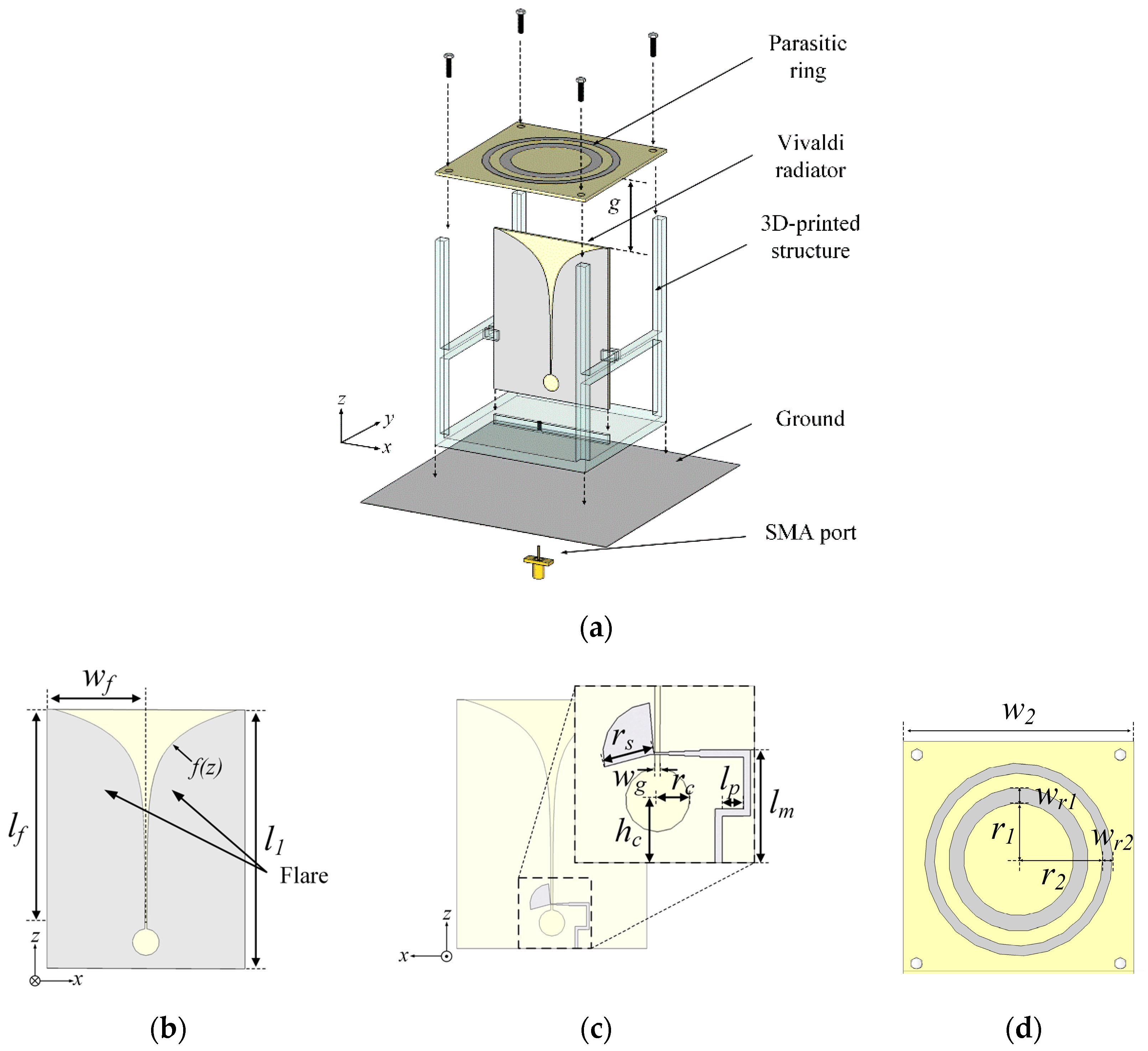
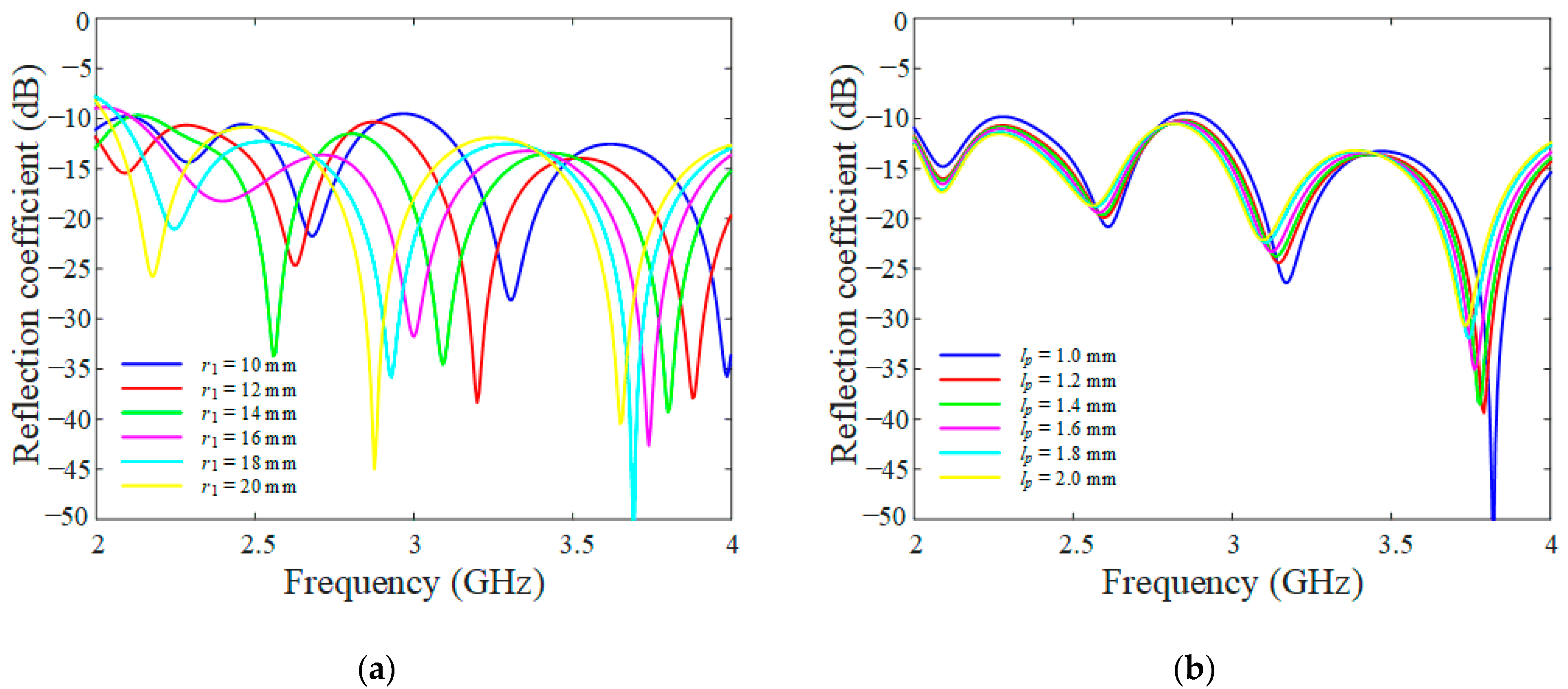
2.1. Single-Element Design

Figure 1 presents the geometry of a single element of the proposed feed array for feeding a large-aperture antenna. To obtain a uniform electric field distribution in the near-field region on a virtual target surface, the proposed element consists of a Vivaldi radiator and the parasitic rings. The parasitic rings are placed on top of the Vivaldi radiators, and the gap between the Vivaldi radiator and the parasitic rings is g, as shown in Figure 1a. The Vivaldi radiator is directly connected to the SMA connector, and the parasitic rings are coupled-fed from the Vivaldi radiator. The Vivaldi radiator and the parasitic rings have different radiating modes, and, in particular, the near-field pattern of the parasitic rings can be varied by adjusting their radii. The Vivaldi radiator and parasitic rings are stably fixed to the ground plane with a resin support structure. This resin structure is fabricated using the stereo lithography apparatus (SLA) 3D printing method. The Vivaldi radiator has two flares and a coupled-fed structure, and they are printed on an FR-4 substrate (εr = 4.6, tanδ = 0.018, thickness = 1.6 mm). The width and length of the flares are wf and lf, respectively, as shown in Figure 1b. The curvature of the inner flares is determined using the function f(z) to achieve broadband characteristics as follows [22,23]:
f ( z ) = a × e k ( z ( l 1 l f ) )
k = 1 l f ln ( 1 a ( w f w g ) + 1 )
where wg is the gap between the two flares, and a is the coefficient of the exponential curve line. On the opposite side of the flares, a microstrip line with a radial stub is printed to feed the antenna through the electromagnetic coupling. The Vivaldi radiator has a circular cavity with a radius of rc, which is located at a distance hc from the ground surface to further improve the antenna bandwidth, as shown in Figure 1c [23]. The parasitic rings consist of inner and outer rings, and the radii of these two rings are r1 and r2, respectively, as shown in Figure 1d. The required near-field distribution on the virtual target surface can be achieved by optimizing the radii of the parasitic rings. The design parameters of the proposed single element have been optimized using a CST Studio Suite 2020 EM simulator [24], and they are listed in Table 1. In addition, the simulation settings are shown in Table 2.
Figure 2 shows the reflection coefficient of the single element of the proposed feed array antenna. The Vivaldi radiator has the advantage of easily achieving broadband characteristics, which exhibits a matching bandwidth of 1.78 GHz (2.21 GHz to 3.99 GHz, |Γ|dB < −10 dB) with a fractional bandwidth of 59%. In addition, the average reflection coefficient in the operating frequency band is −18 dB. There are some discrepancies between the simulated and measured reflection coefficients due to manufacturing and assembly tolerances during the antenna fabrication process. In particular, a connection point with soldering between the transmission line and SMA connector in the Vivaldi radiator is very sensitive to the antenna’s performance. However, the tendency of the measurement is in agreement with the simulated result. The bore-sight gain and HPBW of the single element are 5.91 dBi and 78°, respectively, and the radiation efficiency is 85%.
Figure 3 provides the reflection coefficients according to the radius of the parasitic rings (r1) and transmission line lengths (lp). In Figure 3a, r1 varies from 10 mm to 20 mm with intervals of 2 mm, and in Figure 3b, lp varies from 1 mm to 2 mm with intervals of 0.2 mm. As can be seen, the reflection coefficient is more sensitive to changes in r1, while the lp has little effect on the reflection coefficient.

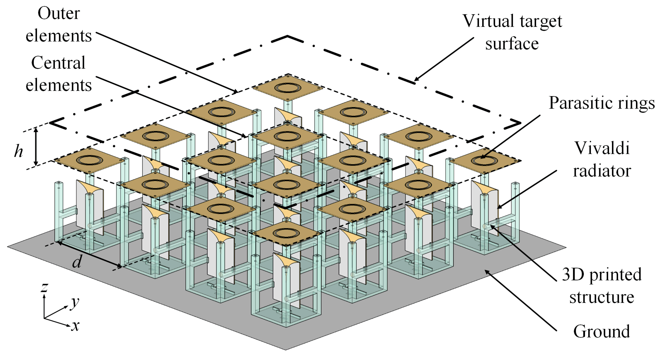
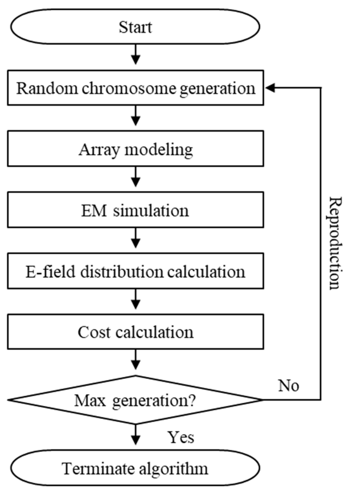
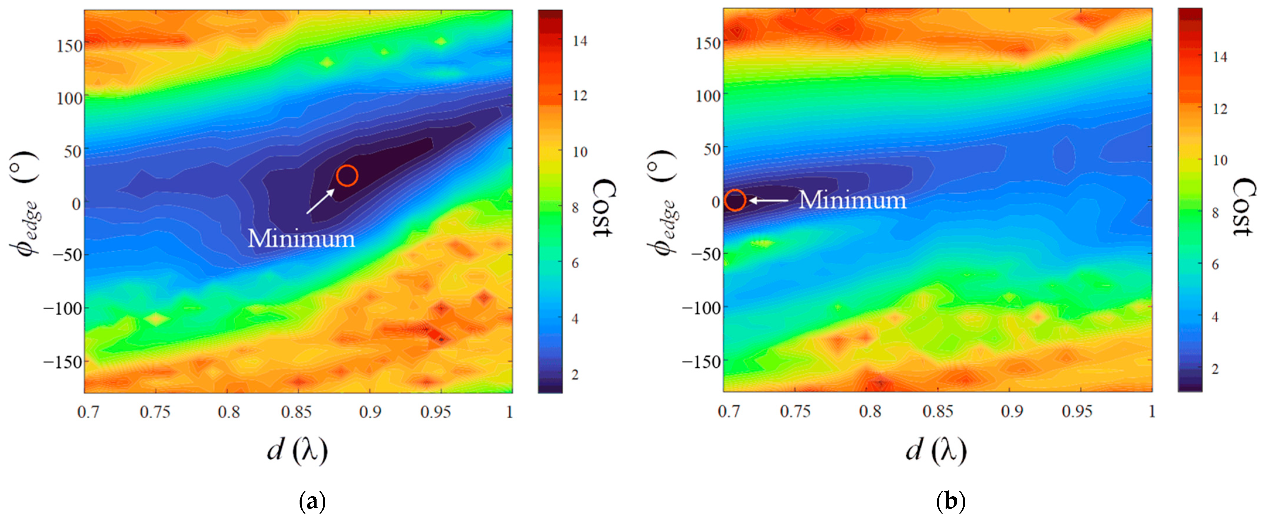
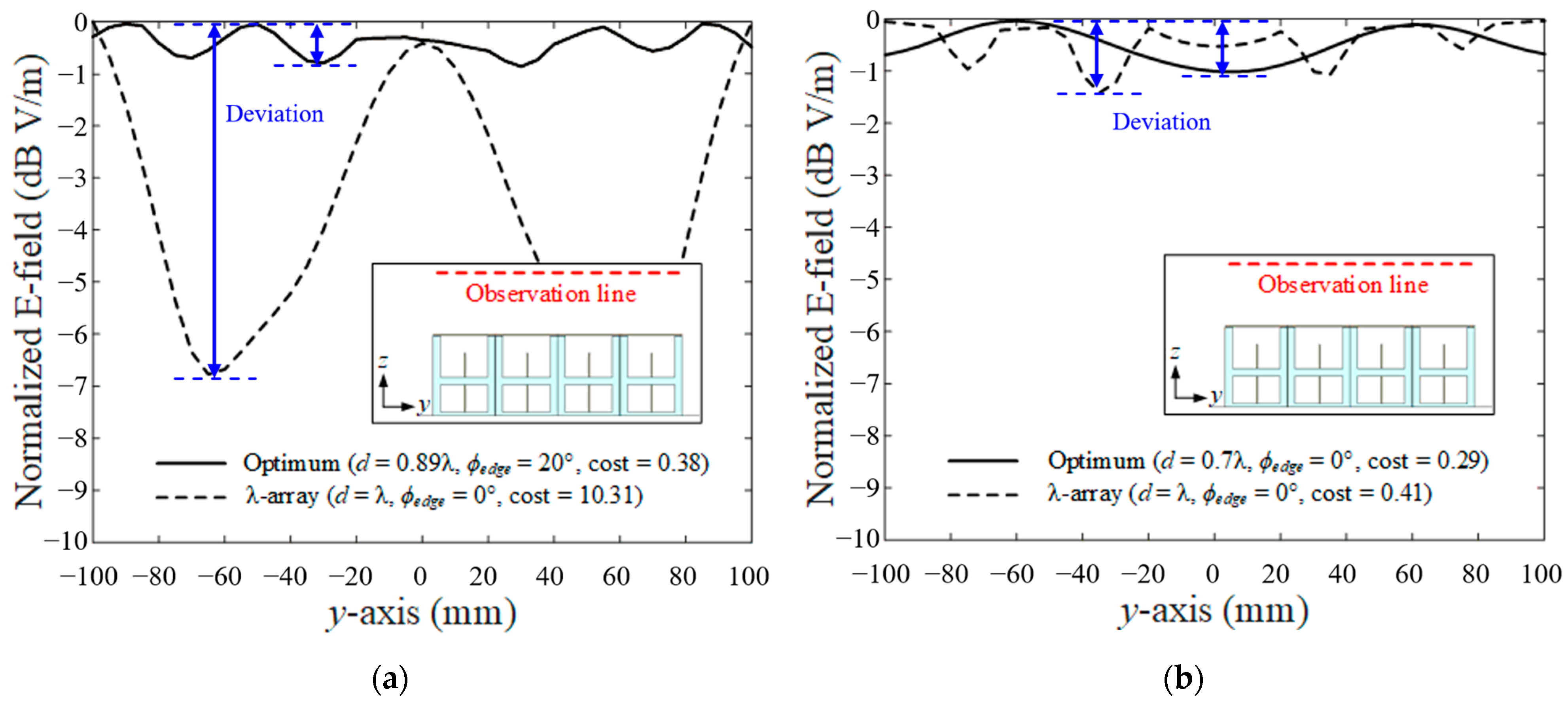
2.2. 4 × 4 Feed Array Design

Figure 4 illustrates the configuration of the proposed feed array for feeding a large-aperture antenna. The feed system has 16 elements with a 4 × 4 rectangular array configuration to obtain the uniform near-field distribution on a virtual target surface. The array spacing in this configuration is d, and the separation distance between the feed array antenna and the virtual target surface is h. The area of this virtual target surface is assumed to be 200 × 200 mm2. The input phase of each Vivaldi radiator is adjusted by applying different transmission line lengths to the Vivaldi radiators depending on their positions in the array. For example, the transmission line length of the central Vivaldi radiator is shorter than that of the Vivaldi radiator placed on the outside of the array. This configuration can easily control the input phase distribution in the array without the use of a complex phase shifter. The input phase delay of the outer element compared to that of the central element is expressed as ϕedge.
Figure 5 shows the flowchart of the GA to optimize the array design parameters such as the array spacing (d), the input phase delay of the outer element (ϕedge), and the separation distance between the feed array and the virtual target surface (h). In this optimization process, we focused on optimizing only the variables for the array configuration to reduce the time and resources required for optimization. To find the optimum design parameters, a random chromosome is created, and the decoded values from the chromosome are then applied to the design parameters of the feed array model. Next, the array antenna model with these design parameters is simulated using the CST Studio Suite EM simulator to calculate the electric field distribution on a virtual target surface. The cost function for the GA is defined as follows:
C o s t = α ( E a v e ) + β ( E d e v )
where Eave is the average value of the electric field distribution used to evaluate the uniformity of the electric field distribution. However, since Eave alone is not suitable for finding the null point of the electric field, we observed not only the average but also the deviation Edev of the electric field. Edev is determined by the deviation between the maximum and minimum values of this electric field distribution. Therefore, the cost function is defined as the summation of Eave and Edev of the electric field distribution. α and β denote the weightings of these two parameters, respectively, and these weights can be adjusted according to the application. In our study, these weights are set to α = 0.7 and β = 0.3. Consequently, the optimum design parameters for the feed array antenna are determined at a minimum cost in the GA, which means that the proposed antenna has the field distribution closest to the uniform distribution on the virtual target surface. The GA parameters, such as the crossover ratio, mutation ratio, number of populations, and number of generations, are listed in Table 3.
Figure 6 presents the variation in the cost value according to the array spacing (d) and the input phase delay (ϕedge) at 3.05 GHz. As can be seen in Figure 6a, when the separation distance between the feed array antenna and the virtual target surface (h) is 0.4λ, the minimum cost value is observed at d = 0.89λ and ϕedge = 20°. On the other hand, when h is 0.6λ, the minimum cost value is indicated at d = 0.7λ and ϕedge = 0°, as shown in Figure 6b.
Figure 7 represents the normalized electric field distribution of the feed array antenna at 3.05 GHz. In this analysis, the electric field distribution is observed along a straight line (x = 0 and −100 mm < y < 100 mm) by varying the height (h). The optimized near-field distribution with design parameters of h = 0.4λ, d = 0.89λ, and ϕedge = 20° are compared with the near-field field when h = 0.4λ, d = 1λ, and ϕedge = 0°. The optimized array has a more uniform field distribution (cost = 0.38) than the other (cost = 10.31), as shown in Figure 7a. When h is 0.6λ, the optimized array (d = 0.7λ and ϕedge = 0°) has a field distribution closest to the uniform (cost = 0.29), as shown in Figure 7b.
Figure 8 shows the simulated cost variation according to the operating frequency. The solid line and dashed line indicate the cost variations of the proposed antenna and the half-wave dipole array, respectively. The results show that the proposed antenna can obtain a more uniform field distribution compared to the conventional half-wave dipole array. In particular, the near-field of the proposed antenna becomes closest to a uniform distribution from 2.6 GHz to 3.3 GHz with a cost of less than 5.

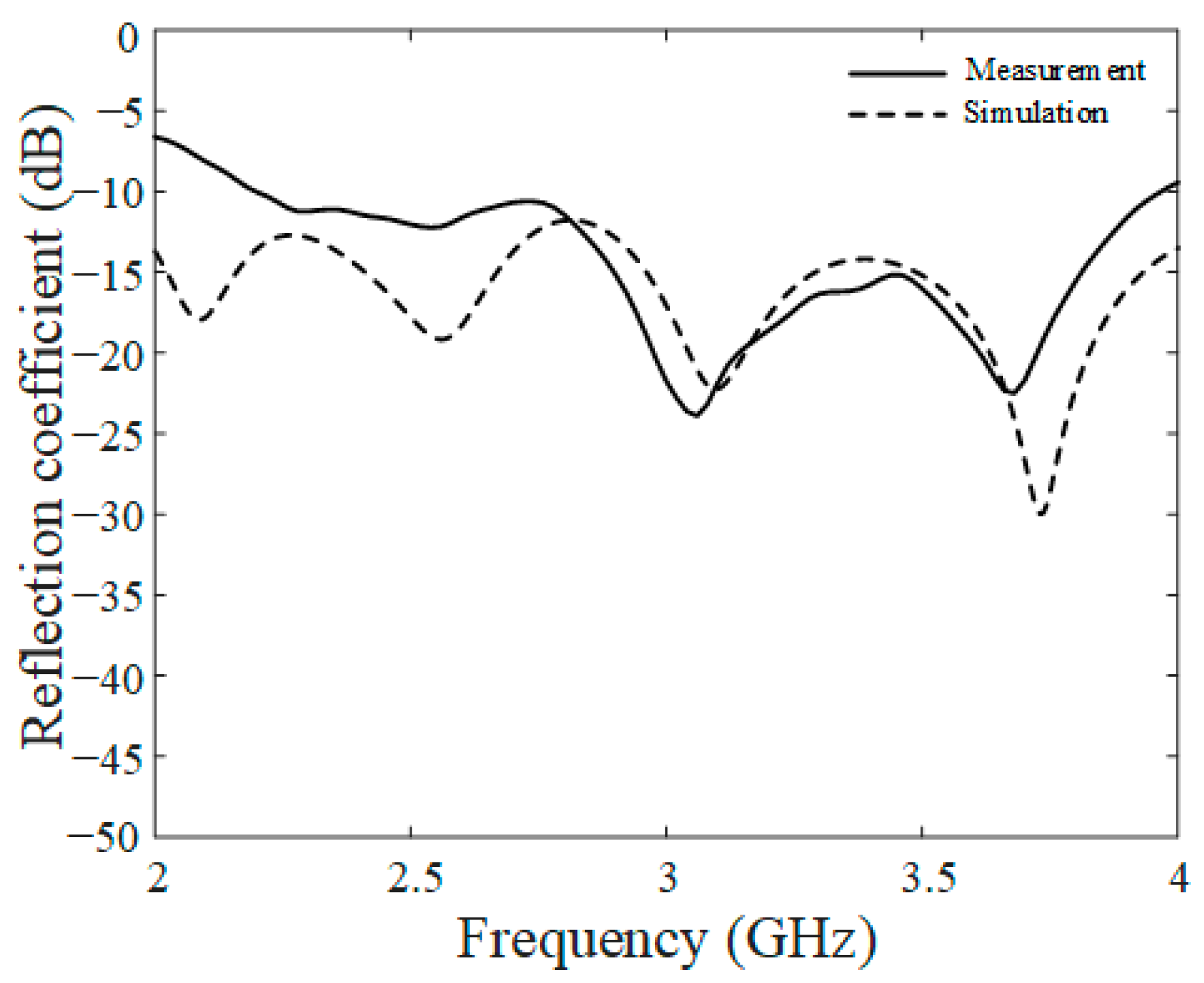
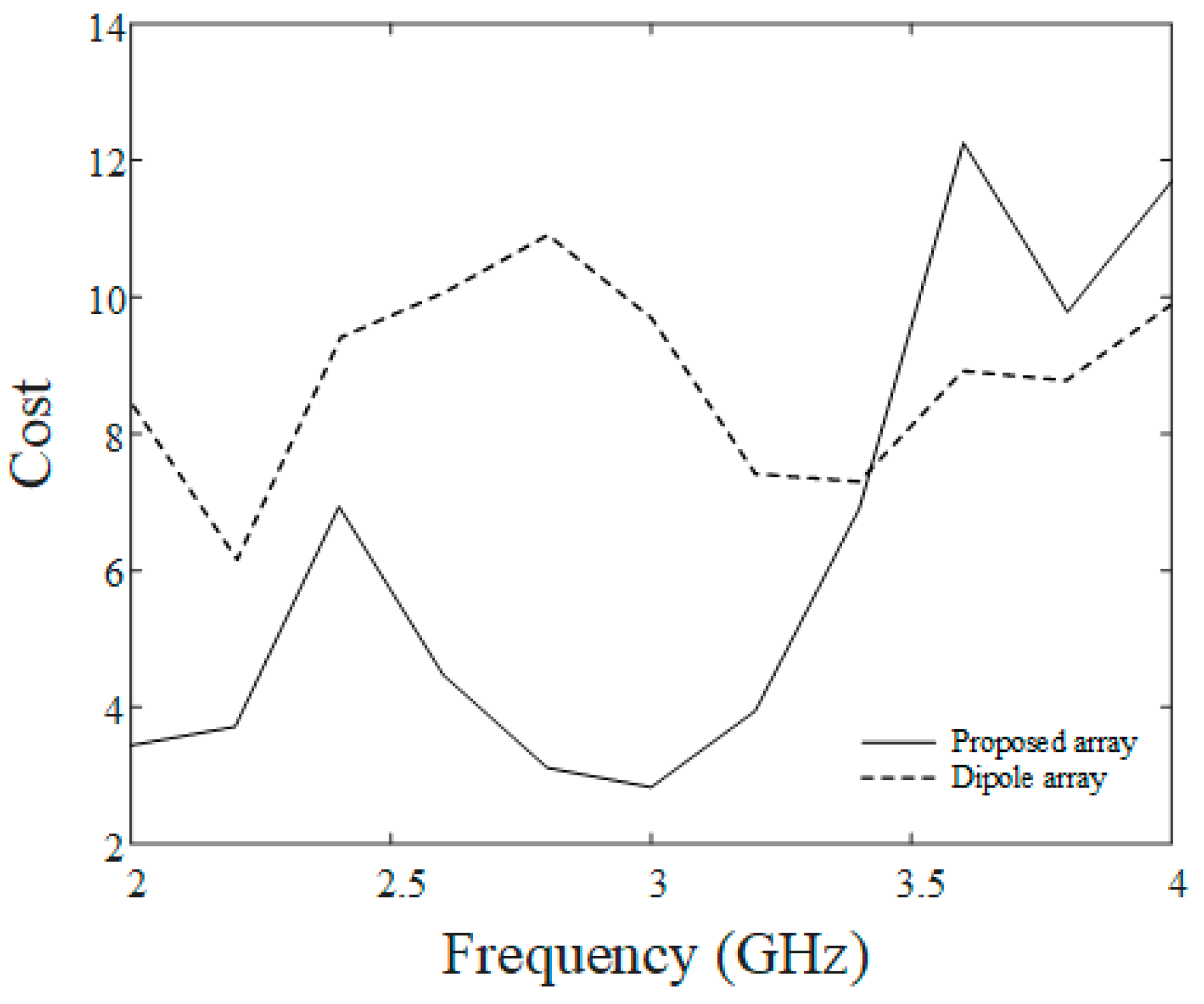
3. Fabrication and Measurement of the Proposed Feed Array Antenna

Figure 9 shows the photographs of the proposed feed array antenna. As can be seen in Figure 9a, the fabricated feed array antenna has 16 elements, and the optimum array design parameters obtained using the GA are applied to the proposed array antenna. To adjust the input phase of each element, the different transmission line lengths are used for the central and outer elements of the array, as shown in Figure 9b,c. The near-field distribution of the proposed feed array antenna is measured in a full anechoic chamber. The dimensions of this chamber are 10 × 10 × 10 m3. A simple waveguide antenna is used as a probe to scan the aperture of the antenna being measured after antenna calibration based on the three-antenna method [25]. Herein, a resolution of the measured near-field data is 0.01 m. SMA connectors are mounted on the bottom face of the ground plane of the array, and all SMA connectors are connected to the network analyzer using five four-way power dividers, as shown in Figure 9d. The array parameters of the proposed feed array antenna are listed in Table 4.
Figure 10 illustrates the normalized electric field distribution of the proposed feed array by measurement and simulation at 3.05 GHz. The electric field distributions are observed to be 30.2 mm (0.3λ) above the aperture of the feed array antenna. The average and deviation of the measured electric field are 1.7 dB and 6.8 dB (cost = 3.2), respectively. This is in good agreement with the simulated results, which are an average of 1.3 dB and a deviation of 6.9 dB (cost = 2.9). The results demonstrate that the feed array with the optimum array configuration and the parasitic rings can obtain uniform electric field distribution in the near-field region.
Table 5 provides the comparisons with other feeders. As can be seen in this table, the feeders in [13,14] are used the single element, which has an advantage of low structural complexity. However, these feed antennas are often mounted in the far-field region, increasing the overall volume of the antenna system. The feeder in [16] is used the array configuration to enhance the uniformity of the near-field distribution. Then, the proposed antenna can achieve the required near-field distribution on the virtual target surface by optimizing the radii of the parasitic rings, transmission line length of each Vivaldi radiator (phase distribution), and array spacing.

4. Conclusions

In this paper, we used a feed array antenna to achieve uniform electric field distribution in the near-field region for feeding a large-aperture antenna. Each element of the array consisted of a Vivaldi radiator and parasitic rings, and it was possible to vary the near-field pattern of the parasitic rings by adjusting their radii. Thus, the required near-field distribution on a virtual target surface can be achieved by optimizing the radii of the parasitic rings. The reflection coefficient of a single element had a matching bandwidth of 1.78 GHz with a fractional bandwidth of 59%, and the average reflection coefficient in the operating frequency was −18 dB. The uniformity of the electric field distribution in the near-field was evaluated by the cost, and this cost was determined by considering both the average and the deviation of the near-electric field distribution. The average and deviation of the proposed feed array were 1.7 dB and 6.8 dB (cost = 3.2), respectively. The result demonstrated that the feed array with the optimum array configuration and parasitic rings can obtain uniform near-field distribution on the virtual surface placed within half a wavelength from the antenna aperture. The proposed antenna can be employed to operate various electrical large-aperture antennas, such as dielectric lens antennas, frequency selective surfaces, and metasurface transmissive arrays. Therefore, we expect that the proposed feed array will be useful in practical applications such as radars, satellite communications, and medical systems [26,27]. On the other hand, the proposed antenna requires further studies to evaluate the antenna’s durability.

Author Contributions

Conceptualization, M.H., D.J. and H.C.; methodology, M.H. and D.J.; software, M.H. and D.J.; validation, M.H., D.J. and H.C.; formal analysis, M.H. and D.J.; investigation, M.H. and D.J.; writing—original draft preparation, M.H.; writing—review and editing, M.H., D.J. and H.C.; visualization, M.H.; supervision, H.C.; project administration, H.C.; funding acquisition, H.C. All authors have read and agreed to the published version of the manuscript.

Funding

This work was supported by the Korea Research Institute for defense Technology planning and advancement (KRIT) grant funded by the Korea government (DAPA (Defense Acquisition Program Administration)) (No. KRIT-CT-22-021, Space Signal Intelligence Research Laboratory, 2022).

Institutional Review Board Statement

Not applicable.

Informed Consent Statement

Not applicable.

Data Availability Statement

Data are contained within the article.

Conflicts of Interest

Author Doyoung Jang was employed by the company Hanwha Systems Company Ltd. The remaining authors declare that the research was conducted in the absence of any commercial or financial relationships that could be construed as a potential conflict of interest.

References

  1. Bouslama, M.; Traii, M.; Denidni, T.A.; Gharsallah, A. Beam-switching antenna with a new reconfigurable frequency selective surface. IEEE Antennas Wirel. Propag. Lett. 2015, 15, 1159–1162. [Google Scholar] [CrossRef]
  2. Wani, Z.; Abegaonkar, M.P.; Koul, S.K. Thin planar metasurface lens for millimeter-wave MIMO applications. IEEE Trans. Antennas Propag. 2022, 70, 692–696. [Google Scholar] [CrossRef]
  3. Hsu, C.Y.; Hwang, L.T.; Horng, T.S.; Wang, S.M.; Chang, F.S.; Dorny, C.N. Transmitarray design with enhanced aperture efficiency using small frequency selective surface cells and discrete Jones matrix analysis. IEEE Trans. Antennas Propag. 2018, 66, 3983–3994. [Google Scholar] [CrossRef]
  4. Malik, B.T.; Doychinov, V.; Zaidi, S.A.R.; Robertson, I.D.; Somjit, N. Antenna gain enhancement by using low-infill 3D-printed dielectric lens antennas. IEEE Access 2019, 7, 102467–102476. [Google Scholar] [CrossRef]
  5. Afzal, M.U.; Esselle, K.P. Steering the beam of medium-to-high gain antennas using near-field phase transformation. IEEE Trans. Antennas Propag. 2017, 65, 1680–1690. [Google Scholar] [CrossRef]
  6. Fallahi, A.; Perruisseau-Carrier, J. Design of tunable biperiodic graphene metasurfaces. Phys. Rev. B 2012, 86, 195408. [Google Scholar] [CrossRef]
  7. Palma, L.D.; Clemente, A.; Dussopt, L.; Sauleau, R.; Potier, P.; Pouliguen, P. Circularly-polarized reconfigurable transmitarray in Ka-band with beam scanning and polarization switching capabilities. IEEE Trans. Antennas Propag. 2017, 65, 529–540. [Google Scholar] [CrossRef]
  8. Xu, H.X.; Cai, T.; Zhuang, Y.Q.; Peng, Q.; Wang, G.M.; Liang, J.G. Dual-mode transmissive metasurface and its applications in multibeam transmitarray. IEEE Trans. Antennas Propag. 2017, 65, 1797–1806. [Google Scholar] [CrossRef]
  9. Wang, J.; Wang, W.; Liu, A.; Guo, M.; Wei, Z. Miniaturized dual-polarized metasurface antenna with high isolation. IEEE Antennas Wirel. Propag. Lett. 2021, 20, 337–341. [Google Scholar] [CrossRef]
  10. Mumcu, G.; Kacar, M.; Mendoza, J. Mm-wave beam steering antenna with reduced hardware complexity using lens antenna subarrays. IEEE Antennas Wirel. Propag. Lett. 2018, 17, 1603–1607. [Google Scholar] [CrossRef]
  11. Qin, F.; Gao, S.S.; Luo, Q.; Mao, C.X.; Gu, C.; Wei, G.; Xu, J.; Li, J.; Wu, C.; Zheng, K.; et al. A simple low-cost shared-aperture dual-band dual-polarized high-gain antenna for synthetic aperture radars. IEEE Trans. Antennas Propag. 2016, 64, 2914–2922. [Google Scholar] [CrossRef]
  12. Xiang, B.J.; Dai, X.; Luk, K.M. A wideband low-cost reconfigurable reflectarray antenna with 1-bit resolution. IEEE Trans. Antennas Propag. 2022, 70, 7439–7447. [Google Scholar] [CrossRef]
  13. Lee, C.H.; Hoang, T.V.; Chi, S.W.; Lee, S.G.; Lee, J.H. Low profile quad-beam circularly polarised antenna using transmissive metasurface. IET Microw. Antennas Propag. 2019, 13, 1690–1698. [Google Scholar] [CrossRef]
  14. Liu, G.; Wang, H.J.; Jiang, J.S.; Xue, F.; Yi, M. A high-efficiency transmitarray antenna using double split ring slot elements. IEEE Antennas Wirel. Propag. Lett. 2015, 14, 1415–1418. [Google Scholar] [CrossRef]
  15. Casula, G.A.; Maxia, P.; Montisci, G.; Mazzarella, G.; Gaudiomonte, F. A printed LPDA fed by a coplanar waveguide for broadband applications. IEEE Antennas Wirel. Propag. Lett. 2013, 12, 1232–1235. [Google Scholar] [CrossRef]
  16. Aziz, A.; Yang, F.; Xu, S.; Li, M. A low-profile quad-beam transmitarray. IEEE Trans. Antennas Propag. 2020, 19, 1340–1344. [Google Scholar] [CrossRef]
  17. Li, T.J.; Wang, G.M.; Cai, T.; Li, H.P.; Liang, J.G.; Lou, J. Broadband folded transmitarray antenna with ultralow-profile based on metasurfaces. IEEE Trans. Antennas Propag. 2021, 69, 7017–7022. [Google Scholar] [CrossRef]
  18. Clemente, A.; Dussopt, L.; Sauleau, R.; Potier, P.; Pouliguen, P. Focal distance reduction of transmit-array antennas using multiple feeds. IEEE Antennas Wirel. Propag. Lett. 2012, 11, 1311–1314. [Google Scholar] [CrossRef]
  19. Lou, Q.; Chen, Z.N. Sidelobe suppression of metalens antenna by amplitude and phase controllable metasurfaces. IEEE Trans. Antennas Propag. 2021, 69, 6977–6981. [Google Scholar] [CrossRef]
  20. Li, M.Y.; Ban, Y.L.; Yan, F.Q. Wideband low-profile Ku-band transmitarray antenna. IEEE Access 2020, 9, 6683–6688. [Google Scholar] [CrossRef]
  21. Srinivas, M.; Patnaik, L.M. Genetic algorithms: A survey. Computer 1994, 27, 17–26. [Google Scholar] [CrossRef]
  22. Ohm, S.; Kang, E.; Lim, T.H.; Choo, H. Design of a dual-polarization all-metal Vivaldi array antenna using a metal 3D printing method for high-power jamming systems. IEEE Access 2023, 11, 35175–35181. [Google Scholar] [CrossRef]
  23. Liu, H.; Liu, Y.; Zhang, W.; Gao, S. An Ultra-Wideband Horizontally Polarized Omnidirectional Circular Connected Vivaldi Antenna Array. IEEE Trans. Antennas Propag. 2017, 65, 4351–4356. [Google Scholar] [CrossRef]
  24. CST Studio Suite: Electromagnetic Field Simulation Software. Available online: http://www.cst.com (accessed on 5 July 2019).
  25. Shi, J.; Cracraft, M.A.; Slattery, K.P.; Yamaguchi, M.; DuBroff, R.E. Calibration and Compensation of Near-Field Scan Measurements. IEEE Trans. Electromagn. Compat. 2005, 47, 642–650. [Google Scholar] [CrossRef]
  26. Gupta, A.; Kumar, V.; Bansal, S.; Alsharif, M.H.; Jahid, A.; Cho, H.S. A miniaturized tri-band implantable antenna for ISM/WMTS/lower UWB/Wi-Fi frequencies. Sensors 2023, 23, 6989. [Google Scholar] [CrossRef]
  27. Gupta, A.; Kumari, M.; Sharma, M.; Alsharif, M.H.; Uthansakul, P.; Uthansakul, M.; Bansal, S. 8-port MIMO antenna at 27 GHz for n261 band and exploring for body-centric communication. PLoS ONE 2024, 19, e0305524. [Google Scholar] [CrossRef]
Figure 1. Geometry of the single element. (a) Isometric view. (b) Front view of the Vivaldi radiator. (c) Back view of the Vivaldi radiator. (d) Top view of the parasitic rings.
Applsci 14 08632 g001
Figure 2. Reflection coefficients of the proposed single element.
Applsci 14 08632 g002
Figure 3. Reflection coefficients of the proposed single element according to r1 (a) and lp (b).
Applsci 14 08632 g003
Figure 4. Geometry of the proposed feed array antenna.
Applsci 14 08632 g004
Figure 5. Flowchart of the GA algorithm.
Applsci 14 08632 g005
Figure 6. Cost variation according to d and ϕedge. (a) h = 0.4λ. (b) h = 0.6λ.
Applsci 14 08632 g006
Figure 7. Normalized electric field distribution of the feed array antenna. (a) h = 0.4λ. (b) h = 0.6λ.
Applsci 14 08632 g007
Figure 8. Cost variation according to operating frequency.
Applsci 14 08632 g008
Figure 9. Photographs of the proposed feed array antenna. (a) The 4 × 4 feed array antenna. (b) Vivaldi radiator of the central elements. (c) Vivaldi radiator of the outer elements. (d) Measurement setup.
Applsci 14 08632 g009aApplsci 14 08632 g009b
Figure 10. Electric field distribution of the proposed feed array. (a) Measurement. (b) Simulation.
Applsci 14 08632 g010
Table 1. Parameters of the proposed single element.
ParametersValues
g24 mm
wf32.15 mm
w285 mm
wr12 mm
l185 mm
lf69.5 mm
r112 mm
r215 mm
rc4.4 mm
rs7 mm
hc8.65 mm
lm15.5 mm
t1.6 mm
a0.01
wg0.7 mm
lp (Central element)0 mm
lp (Outer element)1.8 mm
Table 2. CST simulation environment.
ParametersValues
Solver typeTime domain solver
Mesh typeHexahedral mesh
Mesh size1/15 λ
Boundary conditionOpen boundary
Analysis time range0 to 9 ns
Table 3. Parameters of GA set up.
ParametersValues
Crossover ratio0.8
Mutation ratio0.1
Populations30
Generations30
Table 4. Parameters of proposed feed array antenna.
ParametersValues
d85.4 mm
h30.2 mm
ϕedge24.3°
Table 5. Comparisons with other feeders.
ResearchAntenna TypeStructural ComplexityDistance to the ApertureRegions
[13]Single patchLow1.2 λFar-field
[14]Single hornLow5.4 λFar-field
[16]Slot arrayHigh0.1 λNear-field
This workVivaldi arrayMedium0.3 λNear-field
Disclaimer/Publisher’s Note: The statements, opinions and data contained in all publications are solely those of the individual author(s) and contributor(s) and not of MDPI and/or the editor(s). MDPI and/or the editor(s) disclaim responsibility for any injury to people or property resulting from any ideas, methods, instructions or products referred to in the content.

