Abstract
One of the key issues confronting modern greenhouses is the need to supply the necessary energy in an environmentally friendly manner to facilitate heating and cooling processes within greenhouses. Solar radiation entering the greenhouse during the day can sometimes be more than the energy demand of the greenhouse. In contrast, there are cases where the greenhouse must dissipate a significant amount of heat, absorbed over a long period, either naturally or forcibly, during the cooling process. Moreover, the system’s efficiency could be enhanced if there is a mechanism capable of capturing heat expelled during greenhouse cooling and redistributing it on demand. Employing thermal energy storage is critical for maintaining stable temperatures, assuring energy efficiency, encouraging sustainability, and enabling year-round production. This technique ensures a safe environment for crops and eliminates temperature fluctuations inside the greenhouse. Nocturnal thermal energy storage, storing thermal energy during the daytime for later use at night, is essential to managing a contemporary greenhouse because it promotes consistent crop growth, sustainability, and profitability, particularly in areas with severe winters and significant day-to-night temperature variations. This work reviews various types of thermal energy storage systems employed in previous works focusing on greenhouse applications by researchers and categorizes them based on efficient factors.
1. Introduction
Greenhouses are designed to provide controlled environments for plants to grow and thrive. The walls of a greenhouse can vary in terms of their construction materials, orientation, and insulation properties to regulate the temperature, humidity, and light levels within the structure. Greenhouses come in various types, each designed to serve specific purposes and accommodate different environmental conditions. The first part of this section briefly reviews the different types of greenhouses. The second part discusses the importance of employing thermal energy storage systems (TESSs) in greenhouses.
1.1. Types of Greenhouses
Greenhouses can be categorized based on various factors, including their design, construction materials, purpose, and functionality. Figure 1 demonstrates the main categorizations of greenhouses. These categorizations help differentiate greenhouses based on their specific features and applications, providing options for different climate conditions, crop requirements, and intended uses [1,2].

Figure 1.
Different types of greenhouses [1,2].
1.1.1. Design and Shape
Based on design and shape, greenhouses can be categorized into four models, illustrated in Figure 2. The explanations of these models are listed as follows:
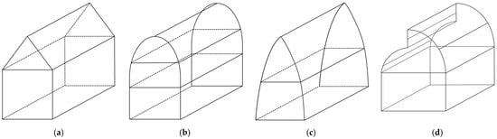
Figure 2.
Different types of greenhouses based on design and shapes: (a) gable roof greenhouses, (b) Quonset (hoop) greenhouses, (c) gothic arch greenhouses, and (d) sawtooth greenhouses.
- Gable roof greenhouses: These have a traditional peaked roof, resembling a house. Gable roof greenhouses have a classic triangular roof shape with ridge vents for superior ventilation and good structural integrity. This design works exceptionally well in colder locations because of the high roof, which makes it easy for snow to slide off and avoid building up. Furthermore, because of their adequate water drainage, gable roof greenhouses are perfect for locations with a lot of rainfall. They can also endure strong winds, which makes them a reliable option for areas with bad weather.
- Quonset (hoop) greenhouses: These have a rounded or curved roof made from metal or plastic pipes. Quonset or hoop greenhouses, renowned for their ease of use and low-cost construction, have a semi-circular or hoop-shaped roof. Because of their compact size, these greenhouses work well in urban and suburban settings and are appropriate for moderate climates without harsh weather. Because they are simple to install and flexible, they are also perfect for short-term or seasonal use. They are a well-liked option for producers on a tight budget because of their affordability.
- Gothic arch greenhouses: These have a pointed or gothic-style roof design, providing better snow-shedding capabilities. Compared to Quonset designs, gothic arch greenhouses have better snow shedding due to their pointed arch roof shape. This greenhouse style blends classic design elements with practicality, making it visually pleasing. It has superior wind resistance compared to Quonset designs, making it appropriate for cold locations where snow accumulation is an issue. Growers who respect performance and aesthetics and live in areas with moderate wind loads should consider gothic arch greenhouses.
- Sawtooth greenhouses: These have a multi-ridged roof resembling a saw blade, with varying heights to optimize light distribution. Because of their open sawtooth structure and asymmetrical roof with one side taller than the other, sawtooth greenhouses provide outstanding natural ventilation. This design works well in hot, humid conditions like tropical and subtropical regions, where controlling indoor temperature and humidity is essential. Because sawtooth greenhouses may be angled to improve ventilation by taking advantage of prevailing breezes, they are also appropriate for areas with changeable wind directions. Therefore, they are perfect for farmers who want effective temperature control without relying too heavily on mechanical equipment.
1.1.2. Covering Materials
Based on the covering materials, greenhouses can be divided into four different cases, which are described and explained below:
- Glass greenhouses: Glass greenhouses have walls and roofs made of glass, providing excellent light transmission and aesthetic appeal. They are often used for commercial flower production and high-value crops. Because of their exceptional light transmission, resilience, and aesthetic appeal, glass greenhouses are well suited to temperate settings with steady sunlight and mild temperatures. They work incredibly well for high-value crops that need exact temperature and light control. Because of their classic, aesthetically pleasant design, these greenhouses are frequently chosen in urban and suburban settings. Because of their durability, they also make a suitable investment for permanent buildings.
- Plastic film greenhouses: Plastic film greenhouses are the most common type covered with polyethylene or other greenhouse-grade plastic. They are cost-effective and versatile, making them popular for various crops and growing conditions. Plastic film greenhouses are an affordable and adaptable option for multiple regions, particularly those with temperature swings. They are appropriate for large-scale agricultural operations and temporary or seasonal use since they are simple to install and replace. Because plastic sheets provide good light diffusion, they improve crop growth conditions. This form of greenhouse is popular for commercial farming, where maintenance costs and convenience are important factors.
- Polycarbonate greenhouses: These use polycarbonate panels as the covering material, providing good insulation and durability. Polycarbonate greenhouses are desired for impact resistance, superior insulation qualities, and lightweight portability. Because of these characteristics, they work effectively in arid climates with severe weather, such as hail, torrential rain, and high winds. Materials made of polycarbonate efficiently insulate and keep internal temperatures steady, which makes them perfect for areas with wide temperature swings. Because of their strength and portability, they are also a popular option for hobby and home greenhouses.
- Shade house greenhouses: Shade houses are designed to provide reduced light intensity for shade-loving plants. They have a shade cloth covering that filters sunlight to the desired level. Shade house greenhouses are ideal for hot, sunny settings, such as tropical and subtropical countries, where reducing heat and light intensity is essential. They offer shading rather than complete enclosure. These structures improve airflow and ventilation, which makes it easier for young seedlings or plants that like shade to flourish. To provide ideal crop-growing conditions during the hottest times of the year, shade rooms are frequently utilized in nurseries and propagation houses. They are also frequently used on a seasonal basis.
1.1.3. Purpose and Use
Greenhouses can be classified into four categories based on their usage and purpose; these categories are explained and discussed below:
- Commercial production greenhouses: these large-scale greenhouses are used for commercial crop production and horticultural purposes.
- Research and experimental greenhouses: these are used for scientific research, plant breeding, and experimentation.
- Educational greenhouses: these are designed for teaching purposes and are often found at schools, universities, and research institutions.
- Retail or display greenhouses: these are used to showcase plants and gardening products to customers.
1.1.4. Structure and Support
Based on their structure and support, greenhouses can be divided into seven groups, which are described below:
- Lean-to greenhouses: Lean-to greenhouses are attached to an existing building, such as a house or a barn. They share one wall with the attached structure, which helps provide support and stability. Lean-to greenhouses are ideal for limited space situations and often benefit from the thermal mass of the existing building.
- Freestanding greenhouses: Freestanding greenhouses are standalone structures that do not rely on existing buildings for support. They can be placed in various locations and come in different shapes and sizes, offering more flexibility in design and layout.
- Ridge-and-furrow (gutter-connected) greenhouses: Also known as gutter-connected greenhouses, ridge-and-furrow greenhouses are a series of interconnected units with a central ridge along the roofline. This design allows for more efficient use of space and resources, as they share structural components and heating systems.
- Dome greenhouses: Dome-shaped greenhouses are geodesic structures that provide excellent strength and energy efficiency. They have a unique appearance and are often chosen for their aesthetic appeal.
- Quonset greenhouses: Quonset greenhouses are rounded or curved structures of metal or plastic pipes covered with greenhouse film. They are easy to construct and cost-effective, making them popular for smaller-scale operations.
- A-frame greenhouses: A-frame greenhouses have a classic triangular roof design. They are easy to construct and provide good snow-shedding capability, making them suitable for regions with heavy snowfall.
- Polytunnel greenhouses: Polytunnels, also known as hoophouses, are simple, low-cost greenhouses with a rounded or arched shape. They are covered with polyethylene or greenhouse plastic and are commonly used for season extension or temporary crop protection.
1.1.5. Climate and Season Extension
Based on the climate and season extension, greenhouses can be divided into two main groups, including (i) seasonal greenhouses and (ii) year-round (perennial) greenhouses. The seasonal greenhouses extend the growing season and protect during colder months. However, the year-round (perennial) greenhouses are designed to operate throughout the year, enabling continuous crop cultivation.
1.1.6. Temperature Regulation
One of the primary categorization schemes for greenhouse systems is this classification, which divides greenhouses into three broad divisions [3]:
- Passive greenhouses rely on natural processes, such as solar radiation and thermal mass, for temperature regulation.
- Active greenhouses use mechanical systems and technology for precise temperature and environmental control.
- Combination of passive and active techniques: In these greenhouses, the greenhouse could be equipped with passive and active techniques in which the leading energy suppliers are the external energy sources; however, the system could be coupled with renewable energy sources like solar collectors, wind turbines, etc.
Passive Greenhouses
A passive greenhouse is a kind of greenhouse in which natural processes mainly control the environment it creates for plant development and temperature regulation. In contrast to active greenhouses, which rely mostly or entirely on outside energy sources to maintain their internal temperature, passive greenhouses operate using mechanical equipment like fans, heaters, and air conditioners [4]. A passive greenhouse’s essential components and ideas are as follows:
- Orientation: Passive greenhouses are strategically designed to maximize exposure to sunlight throughout the day. In colder climates, they are often oriented to face south to capture the maximum amount of solar radiation.
- Thermal mass: Passive greenhouses use materials with a high thermal mass, such as water barrels, masonry, or stones, to absorb and store the sun’s extra radiation heat during the day. These materials release the stored heat at night, helping to maintain a more stable temperature.
- Insulation: Adequate insulation is essential in passive greenhouses to minimize heat loss during colder periods. Properly insulated walls, roofs, and floors help to retain the heat collected during the day.
- Natural ventilation: Passive greenhouses often incorporate adjustable vents, windows, or louvres to facilitate natural ventilation. Ventilation allows for the control of humidity levels and helps to prevent overheating on warmer days.
- Shade management: Passive greenhouses may use shading systems like shade cloth to protect plants from excessive sunlight during the hottest parts of the day.
- Site selection: Choosing the right location for a passive greenhouse is crucial. Factors such as wind exposure, proximity to large structures, and obstacles that could cast shadows should be considered during site selection.
- Plant selection: Choosing plants is also essential in a passive greenhouse. Selecting plant varieties well suited to the local climate and season can contribute to a successful and sustainable growing environment.
Creating a growing place that is more environmentally friendly and energy-efficient is the main objective of a passive greenhouse. Through the utilization of solar energy, thermal mass, and natural ventilation, passive greenhouses can provide a productive and environmentally friendly means of growing plants all year round.
Active Greenhouses
An active greenhouse utilizes mechanical systems and technologies to actively control and regulate the structure’s temperature, humidity, and other environmental conditions. Unlike passive greenhouses, which rely on natural processes for temperature management, active greenhouses use various equipment and systems to create a controlled and optimized growing environment [5,6,7]. The key features of an active greenhouse include the following:
- Climate control systems: Active greenhouses are equipped with sophisticated climate control systems that can monitor and adjust temperature, humidity, and ventilation. These systems may include heaters, fans, evaporative cooling units, misters, and dehumidifiers.
- Automated sensors: Active greenhouses often have sensors strategically placed throughout the structure to measure factors like temperature, humidity, light levels, and CO2 concentration. These sensors provide real-time data to the climate control system, enabling it to make necessary adjustments.
- Heating systems: Active greenhouses have heating systems to raise temperatures during colder periods. These systems can be fueled by electricity, natural gas, propane, or other energy sources.
- Cooling systems: Cooling systems are essential for active greenhouses, especially in hot climates. They may include exhaust fans, evaporative cooling pads, or misting systems to reduce the temperature during warmer periods.
- Ventilation: Active greenhouses have controlled ventilation systems to regulate air exchange and prevent the buildup of excessive heat, humidity, or carbon dioxide.
- Automated irrigation: Many active greenhouses employ automated irrigation systems to give plants the appropriate amount of water at specific intervals.
- Artificial lighting: In some cases, active greenhouses use artificial lighting systems to supplement natural sunlight and extend the daily photoperiod for plant growth.
An active greenhouse’s main advantage is its precise control over the growing environment. By utilizing technology and mechanical systems, growers can create the ideal conditions for various crops and extend the growing season beyond what would be possible outdoors. However, active greenhouses tend to have higher initial setup costs and ongoing operational expenses due to the equipment and energy required to maintain the controlled environment. They are commonly used in commercial agriculture, research facilities, and other settings where crop productivity, quality, and year-round cultivation are essential.
Combination of Passive and Active Techniques
Combining passive and active strategies in greenhouse design makes sense to maximize energy efficiency and establish a more sustainable and regulated environment for plant growth. Passive techniques depend on natural processes, whereas active techniques require technology and external energy sources. By integrating these passive and active techniques, greenhouse operators can create a more sustainable and energy-efficient environment for plant cultivation, optimizing resource utilization and reducing the environmental impact.
Differences between Passive and Active Greenhouses
Passive and active greenhouses are two different types of structures used for plant cultivation. They differ primarily in how they regulate temperature and environmental conditions. Figure 3 illustrates the key differences between passive and active greenhouses, which are explained in the following sections [5,6,7]:

Figure 3.
Key aspects used to differentiate passive and active greenhouses.
- Temperature regulation
A passive greenhouse regulates temperature using natural elements like solar radiation, thermal mass, and ventilation. It incorporates design elements such as proper orientation, insulation, and thermal mass materials to manage heat and cold passively. In contrast, an active greenhouse utilizes mechanical systems, including fans, heaters, cooling units, and automated climate control, to actively control temperature and environmental conditions. Active greenhouses offer precise and rapid adjustments to indoor climate, while passive ones rely on natural processes for temperature regulation.
- Climate suitability
Passive and active greenhouses have distinct suitability based on climate conditions. Passive greenhouses are well suited for regions with moderate climates or areas experiencing sufficient sunlight and temperature variations throughout the year. Their reliance on natural processes makes them effective in environments with these elements. In contrast, active greenhouses offer more versatility and can be employed in a broader range of climates, including colder regions. The mechanical systems in active greenhouses provide precise control over temperature and environmental conditions, allowing them to adapt to a wider spectrum of climate variations.
- Environmental impact
Passive greenhouses typically have a lower environmental footprint, as they consume less energy and rely on natural processes, aligning well with sustainable and eco-friendly practices. Their reduced energy consumption contributes to a more minor environmental impact. On the other hand, active greenhouses tend to have a higher ecological impact due to their reliance on external energy sources, which may involve the consumption of electricity or fossil fuels. The potential greenhouse gas emissions associated with these energy sources contribute to the increased environmental footprint of active greenhouses.
- Complexity and cost
Passive and active greenhouses differ in design complexity, construction, and maintenance considerations. Passive greenhouses are characterized by simpler designs with fewer mechanical components, leading to lower initial construction costs and reduced maintenance needs. Their reliance on natural processes, such as solar radiation, contributes to their simplicity. In contrast, active greenhouses are more complex, involving mechanical systems that result in a higher initial investment. The costs are associated with the purchase and installation of equipment and ongoing energy consumption. Active greenhouses may also require more frequent maintenance and monitoring to ensure the proper functioning of their mechanical components.
- Energy source
Passive and active greenhouses represent two distinct approaches to temperature control. Passive greenhouses operate without external energy sources, relying on natural sunlight and TES to achieve self-sustainability and energy efficiency. In contrast, active greenhouses depend on external energy, typically electricity (like heat pumps) or other fuel sources, to power mechanical systems for temperature control. This fundamental difference highlights the self-sufficiency of passive greenhouses, while active ones rely on ongoing energy input for their operation.
- Off-grid capability
While active greenhouses depend on mechanical systems and outside energy sources, passive greenhouses regulate temperature and humidity through natural processes, and renewable sources are the leading energy suppliers. Accordingly, passive greenhouses can operate off the grid or in remote areas with limited access to a continuous power supply. However, it is worth mentioning that active greenhouses could be coupled with renewable systems to cover both off-grid and on-grid conditions. Moreover, TES allows a greenhouse to operate off the grid or in remote areas. This can be critical for agricultural operations in rural or isolated locations. This system can be integrated into both greenhouses. This method can also be utilized in active greenhouses; however, its application in passive greenhouses is essential. Of course, it is crucial to note that the control system, the main component of active greenhouses, will get more complex as this system is added.
1.2. Application of TES Systems in Various Types of Greenhouses
TES can be applied to various types of greenhouses to improve energy efficiency, optimize temperature regulation, and enhance overall sustainability. The following are some applications of TES in different greenhouse systems [8,9,10,11]:
- Freestanding greenhouses with water barrels: TES can be implemented using water barrels as thermal mass in a freestanding greenhouse. During the day, solar radiation heats the greenhouse and the water barrels, storing the excess heat. During the night, the water barrels gradually release the thermal energy that has been stored, causing a mild heating that keeps the plants at a consistent temperature.
- Glass greenhouses with underground thermal mass: Glass greenhouses often lose more heat than plastic film greenhouses. TES can be applied by incorporating underground thermal mass, such as a buried concrete slab or rock bed. To prevent heat loss and preserve a more constant temperature, the thermal mass absorbs and stores extra heat during the day and releases it at night.
- Polytunnel greenhouses with insulated soil beds: Polytunnel greenhouses can benefit from TES by creating insulated soil beds within the structure. The soil acts as a thermal mass, absorbing solar heat during the day and providing natural heating at night. Additionally, using insulated soil beds reduces heat loss from the ground.
- Shade house greenhouses with cool water storage: TES can manage daytime temperature peaks in shade house greenhouses. Cool water storage systems, such as underground tanks, can store cool water circulated through the greenhouse during hot periods, providing evaporative cooling and reducing the need for additional cooling equipment.
- Quonset greenhouses with phase change materials (PCMs): Quonset greenhouses can benefit from incorporating PCMs as TES. PCMs can store and release large amounts of heat during phase transitions. During the day, the PCM absorbs heat as it changes from a solid to a liquid state, and at night, it releases heat as it changes back to a solid state, maintaining a more stable temperature inside the greenhouse.
- Lean-to greenhouses with Trombe wall: A Trombe wall can serve as TES in a lean-to greenhouse attached to an existing building. The thick, south-facing brick wall stores and collects solar heat during the day and gradually releases it into the interior space at night, thus lowering the need for heating.
TES can be used in various greenhouse systems to improve sustainability, lower energy usage, and more effectively regulate temperature. It allows greenhouse managers to cultivate plants in a more steady and energy-efficient environment, particularly advantageous in areas with seasonal or temperature swings.
1.2.1. Performance of TES in Greenhouses
Solar radiation is accessible throughout the day; however, greenhouse systems confront a significant challenge due to the absence of sunlight at night, mainly because these systems depend on solar energy to maintain the ideal temperature and light levels for plant growth. When temperatures fall sharply in the absence of sunlight, plants get stressed, and their growth is slowed, making energy-intensive heating systems necessary to keep them warm. Artificial lighting is also required to prolong photoperiods due to a lack of natural light, which raises energy expenses even further. In the absence of sun radiation’s drying action, humidity levels can also rise, increasing the risk of fungal infections. Together, these elements increase the complexity and expense of managing greenhouses sustainably and effectively, particularly at night.
Additionally, a considerable amount of heat is lost through the greenhouse walls at night because of the temperature difference between the inside and outside. Because of this, the greenhouse needs a lot of heat, and the heating system must spend a lot of energy to compensate for the heat that escapes through the walls.
Some greenhouses use coverings on their transparent walls to reduce heat loss, but this strategy cannot significantly mitigate heat loss at night. During the day, when solar radiation is abundant, the system uses this heat to meet its demands, while the excess energy is either lost through the transparent walls or stored in the non-transparent wall. However, the amount of heat stored in this manner is minimal.
Given these challenges, using TES systems inside the greenhouse is essential. These systems should absorb excess heat during the day and release it at night to maintain the proper temperature and humidity inside the greenhouse.
1.2.2. Types of TES Systems
TES systems temporarily store thermal energy. These systems are crucial for energy grid integration, improving energy efficiency, and balancing the supply and demand of energy. Many types of TES systems exist based on how thermal energy is stored and released. The categorization of TES systems is demonstrated in Figure 4.
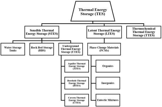
Figure 4.
The categorization of TES systems.
Generally, TES systems are divided into three categories, including (i) sensible thermal energy storage (STES), (ii) latent thermal energy storage (LTES), and (iii) thermochemical thermal energy storage (TTES) systems [12,13].
STES is a sort of TES system in which heat is stored or released by changing a substance’s temperature without changing its phase. Water, rocks, concrete, bricks, molten salts, and air are common storage mediums in STES systems. STES systems respond quickly and reliably to heating or cooling demands while providing excellent thermal efficiency and simplicity of integration into existing infrastructure. Because of their simple form and compatibility with a wide range of materials, they are inexpensive and adaptable to various applications. STES has outstanding efficiency, scalability, and minimal maintenance, making it a viable choice that integrates easily with renewable energy sources, decreases peak energy demand, and contributes considerably to energy efficiency and sustainability [14,15,16].
2. Literature Review
This work covers a literature review of the applications of TES systems in greenhouses. This section is divided into three primary sections, as follows:
- Employing latent heat thermal energy storage (LHTES) systems in greenhouses;
- Employing sensible heat thermal energy storage (SHTES) systems in greenhouses;
- Employing a couple of latent and sensible heat thermal energy storage systems simultaneously in greenhouses.
To clarify the different sub-sections, a graphical abstract of this review paper is illustrated in Figure 5. Accordingly, in the first section, as the applications of LHTES systems in greenhouses, in previous works, LHTES systems were employed and evaluated in three different positions within greenhouses: (i) the opaque wall of the greenhouses, (ii) greenhouse–solar collector hybrid systems, and (iii) directly inside the greenhouses. In the second section, concerning the applications of SHTES systems in greenhouses, previous works evaluated three different systems, including (i) water tanks, (ii) underground TES (UTES) systems, and (iii) rock beds. Also, the UTES systems are separated into two different types: (a) horizontal type and (b) vertical type.
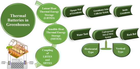
Figure 5.
The graphical abstract of the present review paper to illustrate the applications of thermal batteries in greenhouses.
2.1. LHTES Systems in Greenhouses
2.1.1. LHTES in Opaque Wall of Greenhouses
Typically, greenhouse walls are made of materials that allow sunlight to pass through, such as glass or specialized greenhouse plastic. The orientation of the walls and the greenhouse can affect how much sunlight the plants receive throughout the day. North-facing walls generally receive less direct sunlight, while south-facing walls receive the most.
Figure 6 illustrates the energy transfer processes within greenhouses [17]. During the daytime, solar radiation penetrates through the EVC film on the front roof and is absorbed by the inner surface of the north wall and the soil inside the greenhouse. Solar energy is then collected and stored within the interior of the north wall and soil.

Figure 6.
Energy transfer processes in a greenhouse [17].
As night falls, a thermal insulation curtain covers the front roof. The thermal energy stored in the north wall and soil is now utilized to heat the indoor air on the corresponding surfaces through natural convection. Simultaneously, the surfaces of the other walls are heated through radiation, which helps compensate for any thermal losses to the external environment. This process aids in maintaining a more stable and regulated temperature within the greenhouse during colder periods [18,19,20].
The orientation of a greenhouse is an essential consideration in its design and placement. The north wall of a greenhouse typically receives the least amount of direct sunlight throughout the day. This is because the sun is positioned in the southern sky for locations in the Northern Hemisphere. As a result, the north-facing wall of the greenhouse has the most minor exposure to direct sunlight compared to the other walls. The north wall of a greenhouse is often designed with specific features in mind [21,22,23]:
- Insulation: since the north wall receives less sunlight, it may need to be better insulated to prevent heat loss and maintain a more stable temperature inside the greenhouse, especially during colder seasons.
- Fewer openings: to reduce heat loss, the north wall may have more irregular openings, such as doors and vents, than the other walls.
- Shade-tolerant plants: due to reduced sunlight, shade-tolerant plants are often placed near the north wall of the greenhouse.
- Reflective surfaces: some greenhouse designs incorporate reflective surfaces on the north wall to bounce available sunlight back into the greenhouse and improve overall light distribution.
It is important to note that greenhouse design and construction can vary widely depending on the specific climate, plant types, and the structure’s intended use. Therefore, while the north wall is a general reference point for orientation, actual greenhouse design considerations will depend on various factors specific to each situation.
The researchers suggested and evaluated some methods to solve the problem of the north wall wasting the absorbed energy by the greenhouse. Some are applicable in storing energy inside the greenhouse and solving the greenhouse’s waste behaviour.
In a traditional greenhouse, the primary concern is capturing and retaining heat inside the greenhouse to maintain a suitable temperature for plant growth, especially during colder periods. Various methods are employed to manage heat distribution effectively and prevent excessive heat loss through the north-facing wall, shown in Figure 7 and explained as follows [21,22,23]:

Figure 7.
The employed techniques for preventing heat loss through the north wall of the greenhouse [21,22,23].
- Insulation: The north wall is usually well insulated to reduce heat loss. Proper insulation helps to minimize temperature fluctuations and stabilize the greenhouse environment.
- Thermal mass: Incorporating thermal mass materials, such as water barrels or stone walls (rock), inside the greenhouse can help store excess heat during the day and release it slowly during colder nights, helping to maintain a more stable temperature.
- Reflective surfaces: Some greenhouse designs use reflective materials on the north wall to bounce available sunlight back into the greenhouse, indirectly increasing the overall light and heat levels.
- Efficient heating systems: In colder climates, supplemental heating systems may be used to provide additional heat during extremely cold periods. These systems are typically placed strategically to distribute heat evenly throughout the greenhouse.
- Proper ventilation: Adequate ventilation is essential to prevent excessive heat buildup on warmer days. Ventilation systems, such as ridge vents and side vents, can help regulate the temperature and avoid overheating.
- Location and orientation: Choosing the right place and orientation for the greenhouse can also influence its exposure to sunlight and, consequently, its heat management.
Advanced greenhouse technologies, such as active solar heating, geothermal systems, or heat exchangers, might also be used to optimize energy efficiency and heat distribution. The following is a review of previous works on the applications of LHTES in opaque greenhouse walls.
The thermal performance of a north wall constructed with a PCM as a storage medium in an east–west-oriented greenhouse was examined and addressed by Berroug et al. [24]. As a PCM, CaCl2.6H2O was employed. To explore the influence of the PCM on greenhouse temperature and humidity, a numerical thermal model was built that considered the greenhouse’s different components (cover, plants, inside air, and north wall PCM) and was based on the greenhouse heat and mass balance. Calculations were performed for the average decade climate of January in Morocco. The outcomes demonstrate that with 32.4 kg of PCM per square meter of the greenhouse’s ground surface area, the plants’ and inside air temperatures were found to be 6–12 °C higher at night in the winter with fewer oscillations. At night, the relative humidity was determined to be generally 10% to 15% lower. The components’ energy balance in the greenhouse equipped with a PCM, presented by Berroug et al. [24], is illustrated in Figure 8.

Figure 8.
Greenhouse components’ energy balance equipped with PCM [24].
Because of a thermally stable layer inside the wall caused by the limited heat transfer properties of building materials, the solar energy collected by the wall in passive solar greenhouses is insufficient to heat the interior environment. Ling et al. [25] proposed and introduced a novel system that combines an active–passive triple-phase change material wall (APTPCMW) with solar concentrators to address this issue. An experiment was devised and carried out to explore the active heat storage capability of the APTPCMW. The experiment showed how much the newly proposed system may improve the intermediate layer of the APTPCMW’s heat storage capacity. The APTPCMW’s optimal operating settings were 0.4 m between air tunnels, downward flow direction for heated air within the tunnel, 0.26 m/s supply air velocity, and 60 °C supply air temperature. The experimental setup’s schematic and pictures suggested by Ling et al. [25] are demonstrated in Figure 9.
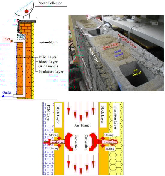
Figure 9.
The suggested experimental setup’s schematic by Ling et al. [25].
Ling et al. [26] conducted a study using both experimental and computational methods to assess the impact of PCMs on the indoor thermal environment of greenhouses under various weather conditions and over an extended period in the heating season. The study was carried out in a typical greenhouse in Beijing, China, and significant parameters, such as the indoor air temperature, outdoor air temperature, solar radiation, surface temperature of greenhouse envelopes, and soil temperature, were regularly recorded for 61 days. The effectiveness of PCMs in greenhouses was assessed using several indicators, including the operative temperature, daily effective accumulative temperature, irradiated surface temperature of the north wall, average temperature of PCMs, and daily heat storage and release. GH-20 PCMs are shape-stabilized solid–liquid PCMs constructed from high-density polyethylene, which supports the PCM while improving heat conductivity, and paraffin wax, which acts as a dispersed phase transition material. In greenhouse applications, the performance of PCMs is significantly influenced by the weather. In contrast to a cloudy day, a bright day will aid in promoting their effectiveness. The experimental setup’s schematic and pictures, considered by Ling et al. [26], are presented in Figure 10.

Figure 10.
The suggested experimental setup’s schematic by Ling et al. [26].
It has been claimed that one effective way to improve the internal thermal climate of solar greenhouses is to apply a PCM to their north wall. Nevertheless, these kinds of walls always have thermally stable layers, significantly limiting their ability to store heat. Chen et al. [27] proposed an active–passive ventilation wall with a PCM to address this problem, and a comparative analysis utilizing both experimental and numerical methods was carried out to show its advantages over conventional walls. The effectiveness of the wall’s middle layer, the inner temperature environment, and plant development were all shown to be positively impacted by the recently suggested strategy, according to estimates or observations of several crucial qualities. The results demonstrated the proposed wall’s high efficacy in raising the temperature of its irradiated surface and middle layer. The newly presented wall had no thermally stable layer, leading to a minimum 1.34 °C temperature rise. Additionally, the suggested solution increased the wall’s capacity to store heat by 35.27–47.89% and release heat by 49.93–60.21%. As a result, the average increase in indoor air temperature, daily effective accumulative temperature, and soil temperature were 1.58–4.16 °C, 33.33–55.06%, and 0.53–1.09 °C, respectively. The fruit yield, stem diameter, and plant height increased by 28%, 25%, and 30%, respectively. The experimental setup’s schematics suggested by Chen et al. [27] are demonstrated in Figure 11.

Figure 11.
The suggested experimental setup’s schematic by Chen et al. [27].
The wall’s thermal characteristics significantly influence the climate inside a solar greenhouse, and crops grown inside can avoid freezing damage by enhancing the material’s ability to retain heat. Guan et al. [28] presented a unique greenhouse wall using PCMs and micro-heat pipe arrays (MHPAs) to increase the temperature of the internal temperature stabilization layer and the wall’s heat storage and heat release capabilities. As a result, a normal greenhouse and an experimental greenhouse with the suggested wall were built. By combining MHPAs with a PCM, the heat transfer bottleneck caused by the PCM’s low thermal conductivity and the traditional wall temperature stabilization layer is effectively resolved, increasing the amount of heat stored in the wall. This ensures crop development at night. The average daily total heat storage for the proposed wall was 18.89 MJ·m−3, compared to 9.67 MJ·m−3 for the conventional wall (95.35% growth). Moreover, the average heat release was 17.58 MJ·m−3, compared to 8.95 MJ·m−3 for a typical wall (96.42% growth), raising the nighttime air temperature and creating an environment favorable for crop development. The suggested system’s schematics and pictures by Guan et al. [28] are demonstrated in Figure 12.
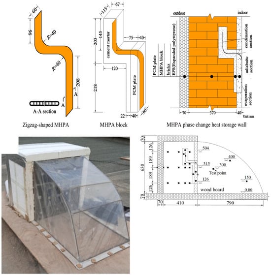
Figure 12.
The suggested system’s schematics and pictures by Guan et al. [28].
2.1.2. LHTES in Greenhouse–Solar Collector Hybrid System
In some greenhouses, solar collectors are used in the vicinity of the greenhouse or inside the greenhouse, and the excess heat of the greenhouse, which is supplied by the sun’s radiation, is absorbed by these collectors. Also, PCM storage is used inside these collectors, which stores the absorbed heat by phase change. At night, when the sun’s radiation is unavailable, the heat stored by this material in the collector returns to the greenhouse environment. In the following, the previous works in the field of the applications of LHTES in greenhouse–solar collector hybrid systems are reviewed.
Öztürk [29] aimed to heat a greenhouse with a 180 m2 floor area utilizing a seasonal TES system using paraffin wax as a PCM and the latent heat storage approach. Five primary components made up the system: (i) flat plate solar air collectors (as a heat collection unit), (ii) a latent heat storage (LHS) unit, (iii) an experimental greenhouse, (iv) a heat transfer unit, and (v) a data gathering unit. The outdoor heat collection unit comprised 27 m2 of south-facing solar air heaters set at a 55-degree tilt angle. The steel tank utilized as the latent heat storage unit had a diameter and a total volume of 11.6 and 1.7 m, respectively. In total, 6000 kg of paraffin was used to fill the LHS unit or 33.33 kg of PCM per square meter of ground surface area in the greenhouse. The system efficiency was assessed using energy and exergy analysis. The LHS unit’s heat transfer rate varied from 1.22 to 2.63 kW, while its rate of heat storage varied from 0.65 to 2.1 kW. The LHS unit transferred and stored thermal exergy at an average daily rate of 111.2 W and 79.9 W, respectively. The average net energy and exergy efficiencies over the trial period were determined to be 40.4% and 4.2%, respectively. During the charging phase, the impact of the heat transfer fluid’s temperature differential at the LHS unit’s input and output on the calculated energy and exergy efficiency values was assessed. The suggested experimental setup’s schematics by Öztürk [29] are demonstrated in Figure 13.
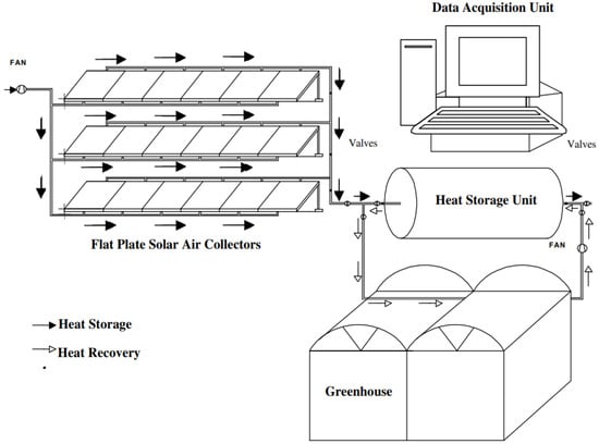
Figure 13.
The suggested experimental setup’s schematic by Öztürk [29].
Benli and Durmuş [30] examined the thermal performance of a PCM storage unit integrated into a greenhouse. The storage unit was part of a heating system of ten separate solar air collectors built for a greenhouse’s interior heating and PCM charging. CaCl2.6H2O, with a melting point of 29 °C, was employed as a PCM. Hot air from a ten-piece solar air collector was routed through the PCM to charge the storage unit. The outside air was heated using the stored heat before entering a greenhouse. The PCM used to examine the transient thermal behaviour of the storage unit during the charge and discharge periods produced experimental data that served as the foundation for this work. Comparing the suggested size of integrated PCM collectors to the traditional heating device, the recommended size of collectors delivered around 18–23% of the greenhouse’s daily thermal energy consumption for 3–4 h. Moreover, the greenhouse’s interior and outside temperatures differed by 6 to 9 °C due to the integration of solar air collectors and PCM systems for the greenhouse. The schematic for the experimental setup suggested by Benli and Durmuş [30] is illustrated in Figure 14.
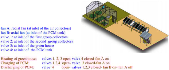
Figure 14.
The suggested experimental setup’s schematic by Benli and Durmuş [30].
Two comparable greenhouses with nocturnal shutters were created and placed in the CRTEn (Research and Technologies Centre of Energy) in Tunisia to minimize energy usage in agricultural greenhouses at night by Kooli et al. [31] and Bouadila et al. [32]. The first had a heating system installed. A collector for solar air heaters that retain latent heat is made up of the sun's heating system. A heating system was included with the first. Thermal solar energy was conserved throughout the day but replenished at night. Furthermore, the shutter was only employed at night. Thermal energy analysis assessed the distribution of absorbed, utilized, stored, and lost energy in the greenhouse, with or without a nighttime shutter. The experimental results showed that the temperature variations overnight in both greenhouses exceeded 2 °C between the first (which had a shutter) and the second (which did not). In addition, the greenhouse’s solar-heated nighttime temperature was maintained at 15 °C even when the outside temperature dropped to 8 °C. At night, the radiation heat loss rate was predicted to be 24% of total heat losses in the greenhouse with a shutter and 61% without a shutter. To summarize, during the cold season in Tunisia in December, the solar system’s quantity of nighttime recovered heat was around 440 W (per volume of collector); that was 62 W (per area of collector) during the entire night inside the greenhouse with a shutter. The experimental setup’s schematic and pictures suggested by Kooli et al. [31] and Bouadila et al. [32] are demonstrated in Figure 15a and Figure 15b, respectively.

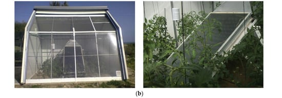
Figure 15.
The suggested experimental setup’s schematic and pictures by (a) Kooli et al. [31] and (b) Bouadila et al. [32].
There are various typical forms of building solar greenhouses. A distinctive thin cover is installed on a unique structure’s curving glass roof. In this instance, the cover adjusts the solar light’s spectral characteristics for multifunctional greenhouse purposes. It reflects the unneeded wavelengths onto a tube collector mounted in the focal line of the curving roof. The fundamental concept of the unique greenhouse stated above was strengthened by Ziapour and Hashtroudi [33]. The effectiveness of the collectors utilized for the roof of the single solar greenhouse system was surveyed. A genetic algorithm optimized the collector tube radius versus the PCM volume. According to the simulation findings, using this solar greenhouse with an improved system has a tremendous impact on both the energy budget and the economy. The system’s schematics suggested by Ziapour and Hashtroudi [33] are shown in Figure 16.
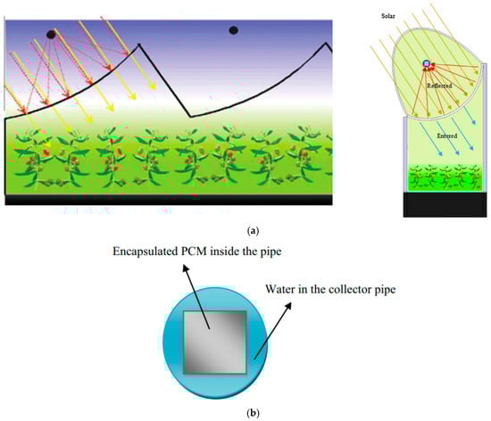
Figure 16.
The suggested system’s schematics by Ziapour and Hashtroudi [33]. (a) considered greenhouse with a curved roof and selective cover and (b) cross-section of collector tube with PCM.
Hydroponic greenhouses promise superior quality, more nutrients, a more significant production, and more effective water and fertilizer usage than traditional greenhouses, but they also need more electricity. Baddadi et al. [34] focused on a new hydroponic greenhouse in Tunisia, installed at the Research and Technology Center of Energy. Considering the application’s thermal loads, a solar air heater with latent thermal storage employing a PCM was also developed for hydroponic greenhouse heating. With the proposed solar air heater with PCM heating, the hydroponic greenhouse’s overnight temperature increased by 6 °C, and the nocturnal temperature was often over 15 °C. The heated hydroponic greenhouse typically had a daily temperature of over 32 °C. Compared to conventional solar heating, the two densely packed beds of latent storage energy improved the greenhouse environment, especially at night and in the cold. The heated hydroponic greenhouse (HG) used for the research and the employed solar air heater with latent storage energy (SAHL) suggested by Baddadi et al. [34] are illustrated in Figure 17a and Figure 17b, respectively.
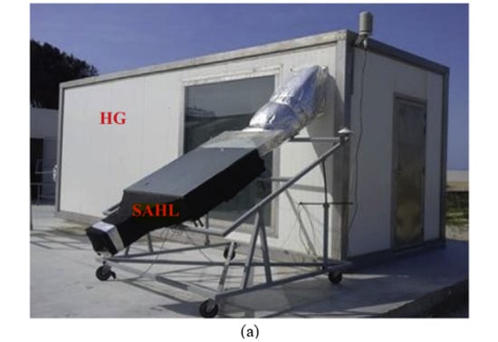
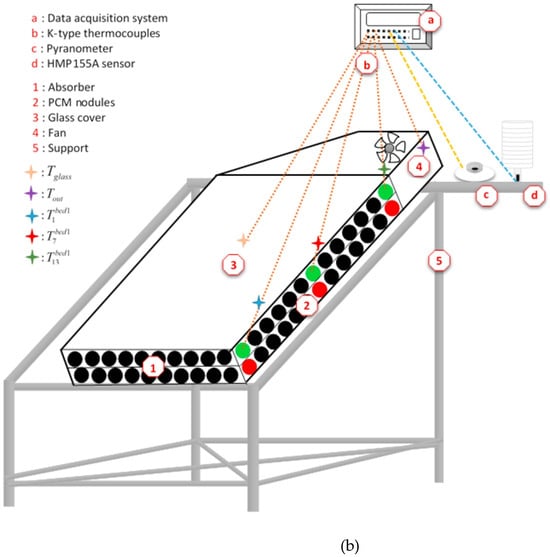
Figure 17.
The suggested system’s schematics by Baddadi et al. [34]: (a) the heated hydroponic greenhouse (HG) used for research and (b) the employed solar air heater with latent storage energy (SAHL).
Solar drying technology has been modified as a superior food preservation method, since direct sunlight has a dangerous risk of microbial assault and a probability of air contamination. Joshua et al. [35] examined a mixed-mode solar dryer for this investigation. The dryer was tested with and without PCM thermal storage. Dry fresh banana and pineapple slices were used to assess the drying performance of both configurations. Using PCM thermal storage resulted in a 75% increase in drying efficiency. The PCM-based dryer’s simple payback period was 1.6 years, less than its 25-year estimated life duration. All sides of the greenhouse were coated with polycarbonate sheets, allowing short-wave light from the sun while blocking out reflected long-wave radiation, creating a regulated atmosphere. Trays were utilized within the greenhouse chamber to store food goods. Two exhaust fans were attached at the top of the greenhouse to remove the majority of the air. This allowed for improved air circulation throughout the whole system. Paraffin wax was kept in cylindrical tubes with both ends shut to prevent outflow when melted. At the bottom of the greenhouse, a tight arrangement of parallel-oriented PCM-filled tubes was present. Solar air collectors absorb solar energy during the day, which causes the air inside them to warm up. The connecting pipes then transfer the heated air to the greenhouse. As a result, some of the heat is retained in the PCM while the other portion is transferred to the greenhouse. Along with the heat provided by the air collector, heat is also produced within the greenhouse during the daytime by solar radiation that is directly absorbed. Together, they dry the food items that are stored in the greenhouse. The PCM is utilized for prolonged drying times with continuous and uniform drying. It becomes heated during the hours of maximum sunlight and releases during the hours of minimum sunlight. The average thermal efficiency attained by the dryer with and without PCM is 30.34% and 23.25% for drying banana and 30.28% and 4.26% for drying pineapple, respectively. With the inclusion of PCM thermal storage, the drying efficacy is increased by 75%. A similar tendency may be seen in the temperature changes and drying rate, indicating that the PCM performs better. The use of a PCM ensures consistent drying and minimizes temperature swings. The payback period was discovered to be roughly 1.6 years, which is appealing given the predicted lifetime of 25 years.
Azaizia et al. [36] provided an experimental study on a new mixed-mode solar greenhouse drying system employing a PCM. The goal was to examine how well red pepper dries when using paraffin wax as the PCM. The drying system comprised two solar greenhouses, a storage container, and two similar solar air heaters. According to the testing findings, the air temperature inside a solar greenhouse with a PCM was approximately 7.5 °C greater than other driers during the whole night. After sunset, the relative humidity in the drying room with a PCM was roughly 18.6% lower than the surrounding air. It was presented that using a PCM in solar greenhouse dryers is a potential solution to improve the effectiveness of the drying process. The system’s schematics and pictures suggested by Azaizia et al. [36] are displayed in Figure 18.
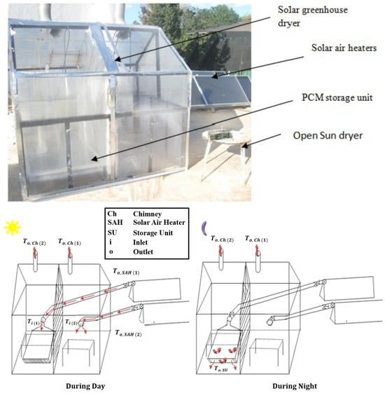
Figure 18.
The suggested system’s schematics and pictures by Azaizia et al. [36].
2.1.3. LHTES inside Greenhouses
In some previous works, the container containing the PCM was used directly and without intermediaries in the greenhouse, which stores the system’s excess solar heat by changing the phase. This heat returns to the system at night. The following is a review of previous works in the field of LHTES applications inside greenhouses.
Shimpy et al. [37] examined the effectiveness of basic and customized greenhouse dryers of groundnuts. A natural convection greenhouse drier was modified using a latent heat storage unit (LHSU) packed with beeswax as a PCM. Groundnut samples were dried at GJUST (Hisar, India) in June 2019 using a modified greenhouse dryer (MGHD) and a simple greenhouse dryer (SGHD). When a groundnut sample was dried under the MGHD, 23.45% more moisture evaporated than when it was dried under the SGHD. Also, more tremendous greenhouse energy and exergy efficiencies were discovered for the MGHD. Moreover, groundnut-drying-specific energy use was 67.16% lower in the MGHD. Figure 19 presents the suggested system’s schematics by Shimpy et al. [37].
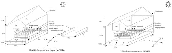
Figure 19.
The suggested system’s schematics by Shimpy et al. [37].
Yang et al. [38] proposed a transparent envelope with a PCM (PTE) incorporated into usual plastic greenhouses to respond to dynamic variations in temperature and daylight. The PTE can function as a governor to balance light and thermal performance, in contrast to opaque structures combined with a PCM. The performance of the proposed plastic greenhouses incorporating PTEs in terms of photothermal efficiency was experimentally investigated by Yang et al. [38]. The various PCM melting temperatures (three different temperatures) and the seasons (transition, fall, and winter) were compared in a logically built plastic greenhouse with adjustable interior lighting and air temperature. The findings demonstrate that PTE-equipped plastic greenhouses significantly adjust thermal energy storage and release while reducing inside sunshine. Due to the lower outdoor temperature and sunlight, PTEs with low melting temperatures are beneficial. Understanding built-in PTEs can assist in identifying the optimal states to construct a low-cost, readily replaced passive heating system for plastic greenhouses. The suggested system’s schematics and pictures by Yang et al. [38] are demonstrated in Figure 20.
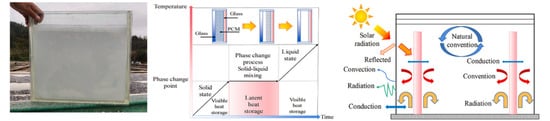
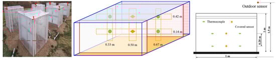
Figure 20.
The suggested system’s schematics and pictures by Yang et al. [38].
Root zone heating systems improve crop quality and output. These systems, however, are predicated on the utilization of nonrenewable fuels. Llorach-Massana et al. [39] described an investigation into several design possibilities for a root zone heating system based on thermal energy storage using a PCM. They determined the most efficient PCM melting/freezing temperature and location concerning the substrate (i.e., under the substrate) for the application under consideration and the system’s environmental and economic feasibility, using life cycle assessment and life cycle cost methodologies. The results reveal that the ideal melting temperature for the application is 15 degrees Celsius. The perlite bag should be wrapped in the material to shield the PCM from atmospheric temperatures. Based on preliminary findings from a single night, the PCM appears to be able to lessen the environmental impact of traditional gas and oil root zone heating systems. The schematics of the suggested experimental setup by Llorach-Massana et al. [39] are presented in Figure 21.
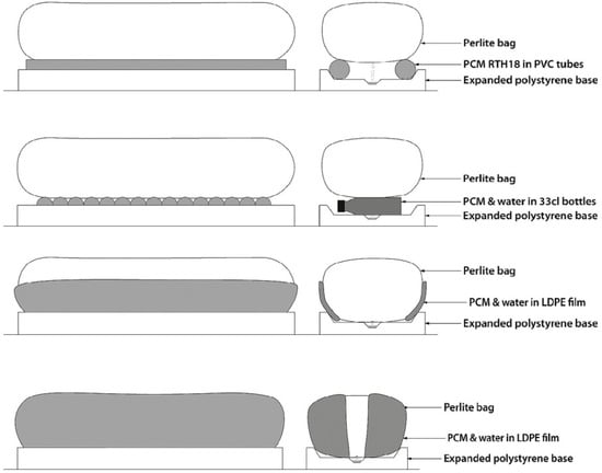
Figure 21.
The suggested experimental setup’s schematics by Llorach-Massana et al. [39].
2.1.4. Categorization of Previous Works on Greenhouse LHTES System Based on Efficient Factors
Table 1 categorizes the results from earlier publications linked to using PCMs in greenhouses as a TES system. Different aspects of these works are focused on, including the year of publication, type of work (experimental, numerical, analytical, etc.), type of PCM, product or crop of the greenhouse, evaluated factors, and outcomes (qualitative and quantitative). Indeed, as evidenced by the items listed in the table, research related to this topic was published between 2005 and 2023. This extensive timeframe, spanning nearly two decades, underscores the thorough examination and analysis researchers undertake. The results have been promising, inspiring researchers to enhance PCMs’ coupling efficiency within greenhouse environments across various operational scenarios.

Table 1.
The literature review of previous work concerning the applications of PCMs in greenhouses.
Table 1 also demonstrates that most of the studies in this sector have been conducted experimentally, with less statistical or analytical investigation of the usage of PCMs in greenhouses. This issue might be viewed as a research gap that should be addressed in future studies. A precise and more detailed understanding of this material’s phase change process is required to understand better the effect of using a PCM inside greenhouses for storing energy in the charge state and releasing it in the discharge state. Numerical simulation, due to its tremendous capabilities, can be an outstanding idea for achieving this.
Concerning the PCM employed in greenhouses equipped with a PCM as TES, the details in Table 1 demonstrated that, in general, six different types of PCMs were used in these systems, including pure paraffin, calcium chloride hexahydrate (CaCl2.6H2O), GH-20, AC27, RT types (RT12, RT15, and RT18HC), and shape-stabilized PCMs. It can be concluded that paraffin is the most commonly used PCM among the materials employed.
In terms of the kind of greenhouse usage and the product or crop utilized in the research, Table 1 demonstrates that the type of product is indicated in some studies but not in others. Knowing the product type in the greenhouse aids future analysis; if the researcher plans to model and evaluate the intended system mathematically, the quantity of heat and humidity required for the desired product is essential. Modelling will be intricate without it.
Most research on this subject compared greenhouse systems outfitted with PCMs to simple greenhouse systems (without PCMs), and the temperature and humidity within the greenhouses at different times of the day and night have been compared and evaluated. The PCM’s primary function within the greenhouse is to store extra and lost energy throughout the day in a way that does not interfere with the ideal temperature and humidity inside the greenhouse. The absence of sun radiation causes a significant temperature drop within the greenhouse throughout the night. In this situation, the PCM comes to the system’s help, regulating the temperature and humidity within the greenhouse at night by releasing the absorbed heat during the day. As a result, while employing PCM-equipped systems, it is critical to build a suitable system by considering the precise values for the effective parameters. The placement and amount of the PCM should be chosen so that the PCM can absorb the possible highest amount of lost heat and the daily functioning of the greenhouse is not disrupted.
The researchers’ findings reveal that using the PCM within the greenhouse substantially influences its night performance, and the proposed system significantly improves the temperature and humidity at night. For instance, Azaizia et al. [36] provided an experimental study on a new mixed-mode solar greenhouse drying system, both with and without a PCM as a TES unit. They presented that the air temperature inside a solar greenhouse with a PCM is approximately 7.5 °C greater than other driers during the whole night. Also, the relative humidity in the drying room with a PCM is roughly 18.6% lower than the surrounding air.
2.2. SHTES Systems in Greenhouses
2.2.1. Water Tank as SHTES System
To control temperature and maximize energy efficiency, employing a water tank as a TES system in greenhouses, particularly in cold regions with harsh winters, is a sensible practice. You can use solar collectors or other heat sources to reheat the water in the tank on hot days or different periods of excess heat. The water efficiently stores heat because it acts as a thermal mass. The thermal energy stored in the water tank may be released to keep the greenhouse’s temperature constant and comfortable when needed, such as throughout the night or during cold seasons. In addition to shielding plants from bitter cold, this technology helps maintain ideal growth conditions by reducing temperature swings. In the following, the previous works in the field of the applications of SHTES systems in greenhouses are reviewed.
Chinese solar greenhouses intended for nighttime heating require a north wall with a high thermal capacity. Nevertheless, because of their poor heat conduction, which prevents heat from moving from the wall’s surface to its depth, the north wall’s capacity to store thermal energy using conventional construction materials is restricted. Xu et al. [40] incorporated an active solar water wall made of hollow polycarbonate sheets into the north wall and an underground water storage tank to raise the temperature at night. Its abilities to gather and release solar heat, increase the greenhouse temperature at night, and function thermally in inclement weather were all considered during its evaluation. An average of 85.8% of the heat was captured, of which 80.4% was discharged for greenhouse heating. The average minimum nightly air temperature rose by 3.3 °C compared to the scenario without the water wall. They presented that by removing the need for additional heating, retrofitting Chinese solar greenhouses with water walls can enable the cultivation of warm-season crops all winter long. The schematics of the proposed system by Xu et al. [40] are demonstrated in Figure 22.

Figure 22.
The schematics of the proposed system by Xu et al. [40]. (A) 3D view, (B) 2D view (front), and (C) 2D view (side).
In a Chinese solar greenhouse, Wang et al. [41] provided a theoretical foundation for the system’s installation location and collector size based on solar radiation. A solar water heating system (SWHS) consisting of a sheet heating system was placed on the north wall of a Chinese greenhouse near Beijing. The findings showed an average rise of 3.1 °C in the lowest nightly interior temperature. In January, the time period for keeping the nighttime internal temperatures higher than 8.0 °C makes up 80.0%. The schematics of the proposed system by Wang et al. [41] are depicted in Figure 23.
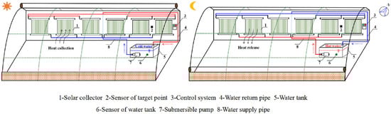
Figure 23.
The schematics of the proposed system by Wang et al. [41] (red line: hot water–blue line: cold water).
2.2.2. Underground Thermal Energy Storage (UTES) System as SHTES System
The UTES technique includes storing and recovering thermal energy from underground geological formations. This method enhances energy efficiency and sustainability by enabling the storage of extra energy for later use. UTES is classified into three primary categories [42]:
- Aquifer Thermal Energy Storage (ATES): This involves injecting surplus thermal energy, usually from sources like solar collectors or industrial processes, into an underground aquifer during periods of low energy demand. The stored heat is then extracted for space heating or other applications when needed, typically during colder periods.
- Borehole Thermal Energy Storage (BTES): BTES systems use a network of boreholes drilled deep into the ground to store and retrieve thermal energy. Like ATES, excess heat is stored in the ground during warm periods and extracted during colder periods. Heat exchange fluid circulating through the boreholes facilitates the transfer of thermal energy.
- Seasonal Thermal Energy Storage (STES): STES involves storing thermal energy for more extended periods, typically from one season to another. This can be achieved using underground structures, such as large rock or water reservoirs, where heat is stored during warmer seasons and extracted during colder periods.
BTES proves highly beneficial in greenhouses by efficiently managing seasonal heating and cooling demands. The technology allows for storing excess thermal energy during periods of surplus, such as hot summer days, and its retrieval during colder periods, offering a sustainable and reliable heating source. By reducing the reliance on conventional energy sources, BTES helps minimize operational costs and contributes to environmental sustainability. It enables consistent temperature regulation for optimal plant growth, improves crop yields, and can be integrated with various renewable energy sources, aligning with greenhouse operators’ goals to enhance energy efficiency and reduce environmental impact. Additionally, BTES is valuable for off-grid applications, providing a self-sufficient energy solution for remote greenhouse locations [43].
Generally, there are two types of BTES, including (I) Horizontal Borehole Thermal Energy Storage (HBTES) and (II) Vertical Borehole Thermal Energy Storage (VBTES). HBTES and VBTES differ primarily in their orientation and spatial requirements. HBTES involves drilling boreholes parallel to the ground surface, making it suitable for sites with ample horizontal space. In contrast, VBTES requires vertical boreholes, making it more space-efficient for areas with limited horizontal space. HBTES typically features shallower boreholes spread over a larger area, while VBTES involves deeper, vertically drilled boreholes concentrated in a smaller space. The choice between the two depends on factors such as the geological conditions, available space, and specific energy storage needs, with both configurations serving as effective methods for Seasonal Thermal Energy Storage in applications like heating and cooling systems for buildings or greenhouses [43].
Horizontal Borehole Thermal Energy Storage (HBTES)
Awani et al. [44] emphasized the usage of heat pumps connected to solar collectors and HBTES heat exchangers in both computational and experimental studies to maximize the use of renewable energy sources for greenhouse heating. Their research illustrated how well a heat pump system performed in Tunisia’s climate with help from solar and geothermal energy. They presented that solar and geothermal energy-assisted heat pumps can save conventional energy and compete with traditional heating systems in heating mode. Also, because the drops in ground temperature during the experimental tests did not surpass 1 °C, the HBTES heat exchanger may be utilized successfully for heating greenhouses. The schematics of the proposed system by Awani et al. [44] are depicted in Figure 24.
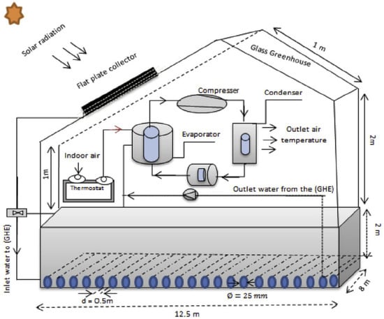
Figure 24.
The schematics of the proposed system by Awani et al. [44].
Over the last few decades, solar and geothermal energy have been routinely employed to heat greenhouses. However, solar energy was inaccessible at night, and geothermal energy was frequently provided at a significant capital cost. Luo et al. [45] suggested a unique Geothermal Battery Energy Storage (GBES) system that combines solar heat storage with geothermal energy to heat a greenhouse. The system was evaluated in three different modes of operation. The GBES-based greenhouse had a temperature that was 3.7 °C higher than a traditional greenhouse in Mode A. By overlaying a double-layer membrane for the greenhouse in Mode B, the temperature was even 6.6 °C higher than in Mode A, since the system’s insulation efficiently inhibits heat loss. When the system was further heated intermittently, Mode C maintained the same energy efficiency as Mode B while conserving 40% of the input energy.
Furthermore, the GBES system’s coefficient of performance (COP) may reach up to 5.9, 1.6 times greater than a traditional geothermal greenhouse, at a relatively low capital and operational cost. The suggested GBES technology showed potential for low-cost temperature stabilization in a greenhouse. The schematics and pictures of the proposed system by Luo et al. [45] are demonstrated in Figure 25.

Figure 25.
The schematics and pictures of the proposed system by Luo et al. [45]. (a) lower pipe buried at a depth of 1.2 m, (b) upper pipe buried at a depth of 0.7 m, (c) propeller fans positions, and (d) greenhouses Nos. 1 and 2. pictures.
Vertical Borehole Thermal Energy Storage (VBTES)
Li et al. [46] investigated the long-term operation and environmental impacts of a sizable ground source heat pump (GSHP) system that heated and cooled industrial greenhouses in a cold climate using both field data and a numerical simulation. In the northern Japanese province of Hokkaido, a sizable vertical GSHP system was set up to heat and cool twelve greenhouses. The system’s highest heating and cooling capacities are 640 and 648 kW, respectively. The system was observed and examined between October 2010 and May 2011. After eight months of operation, the ground temperature at a depth of 40 m dropped from around 7.8 °C to 0 °C. The simulation’s findings imply that the system’s performance would not be materially jeopardized if the heat exchange rate was maintained for several years. Case studies addressed the danger of running the system under imbalanced heating and cooling loads. Operating the system when the heat extraction is much more significant or lower than the heat injection is made less risky by groundwater flow. The schematics of the proposed approach by Li et al. [46] are demonstrated in Figure 26.
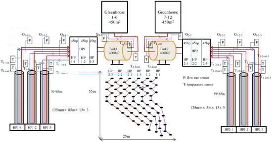
Figure 26.
The schematics of the proposed system by Li et al. [46].
An experimental investigation was conducted by Boughanmi et al. [47] to evaluate the effectiveness of a novel conic basket geothermal heat exchanger (CBGHE) for greenhouse cooling. A sequence of parallel coils implanted at a depth of three meters usually made up the arrangement. The tests were in June 2014, on June 7 and 8. The outcomes demonstrated that the CBGHE system could be applied to greenhouse cooling in Mediterranean locations like Tunisia. The most considerable amount of heat the CBGHE could transmit to the ground during the experiment was around 8 kW. With a recorded mass flow rate of 0.08 kg·s−1, the most significant average temperature difference between the CBGHE system’s intake and output was about 30 °C. Within the greenhouse, the air temperature dropped by approximately 12 °C. The schematics of the proposed system by Boughanmi et al. [47] are demonstrated in Figure 27.

Figure 27.
The schematics of the proposed system by Boughanmi et al. [47].
2.2.3. Rock Bed as SHTES System
Using a rock bed as the TES system involves capturing heat, frequently from solar or other renewable sources, and transferring it to rocks via a heat transfer fluid. Because of their adequate thermal capacity, rocks store this energy as perceptible heat. The stored heat is extracted and used to heat the area or water on demand. This method has advantages like long-term storage and durability but drawbacks such as delayed heat release and sufficient insulation. For effective implementation, site-specific factors and technological improvements must be carefully considered.
Rock beds may be used efficiently in greenhouses to increase temperature control and energy efficiency. The granite bed acts as a thermal mass in this application, storing extra heat during periods of solar gain and gradually releasing it during cooler periods. The pebbles in the bed absorb heat throughout the day when the greenhouse receives enough sunshine. As temperatures fall in the evenings or during gloomy times, the stored heat is gradually released, assisting in maintaining a more steady and appropriate temperature for plant development. This thermal buffering effect can help to provide a more stable and regulated climate within the greenhouse, which reduces the need for extra heating or cooling equipment. Previous efforts on the use of rock beds, particularly in greenhouses, will be covered in the following sections.
Bouhdjar et al. [48], in 1996, presented an experimental investigation of sensible energy storage in a rock bed in horizontally arranged cylindrical ducts beneath the soil in a tunnel greenhouse. The study showed that the rock bed is practical by analyzing many recorded data, namely the rock bed’s input and outflow temperatures and sun radiation. Compared to a conventional greenhouse (without TES), the greenhouse’s temperature was raised due to the heat returned to it by the rock bed as the TES system. Plants may be sufficiently protected from the detrimental low temperatures that may occur in the Algiers region during the winter months by the heat supplied by the storage, which was stated as a temperature elevation of up to 7 °C over the outside temperature. The schematics of the proposed system by Bouhdjar et al. [48] are demonstrated in Figure 28. In this figure, different parts of the proposed system are shown separately. It is worth mentioning that a blower is connected to the pipes installed in the rock bed to transfer the inside air of the greenhouse to the rock bed environment for heating or cooling purposes.
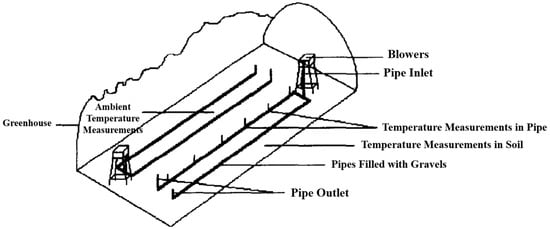
Figure 28.
The schematics of the proposed system by Bouhdjar et al. [48].
Kurklu et al. [49] researched the possibility of storing solar energy for greenhouse heating in an underground rock bed. Two identical polyethylene tunnel greenhouses, each with a 15 m2 ground area, were used for the experiments. One of the greenhouses had two ditches dug and insulated in its soil; the ditches were filled with rocks. The greenhouse air was driven through the rock bed by a centrifugal fan with an airflow rate of 1100 m3/h. The fan was controlled by two thermostats that released or stored energy as needed. The greenhouses were not used to grow crops, and the vents were kept covered unless extremely humid conditions existed. This study showed that, even after a clear day, the rock bed system maintained the inside air temperature above the outside air temperature at night. The system’s energy recovery or release efficiency was higher than 80%, despite its 34% solar energy collection efficiency. A numerical mathematical model accurately reflected real facts. An economic analysis indicates that the rock bed system is more economical than the fuel-burning heating systems commonly used in Turkish greenhouses, which burn LPG or petroleum. The rock bed system caused a 6–9 °C temperature difference between the air within and outside. The schematics of the proposed system by Kürklü et al. [49] are demonstrated in Figure 29.

Figure 29.
The schematics of the proposed system by Kurklu et al. [49]: (a) front view and (b) side view.
To investigate the usage of a greenhouse with packed beds of thermal storage for crop drying, Jain [50] proposed a transient analytical model. The effectiveness of an even-shaped greenhouse with a packed bed and crop drier was assessed for drying onions. The model was solved to determine the air temperatures and other drying system functioning components for a day in May for Delhi’s (India) meteorological conditions. The parametric study examined the relationship between the greenhouse length, width, air mass flow rate, and crop temperature. The drying rate and hourly decrease in moisture content in the crop trays were studied using the thin-layer drying equation. It was noted that as the day wore on, the crop’s moisture content and drying rate decreased, which was an obvious result. They illustrated that in a 24 h drying time, a greenhouse with dimensions of 6 m long, 4 m wide, 0.278 kg·s−1 air mass flow rate, and 0.25 m height of packed bed could dry 2280 kg of onions with a moisture content ratio of 6.14–0.21 kg water to kg of dry matter. The schematics of the proposed system by Jain [50] are demonstrated in Figure 30.
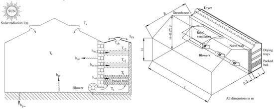
Figure 30.
The schematics of the proposed system by Jain [50].
Bazgaou et al. [51] examined and discussed the effectiveness of a rock bed heating system (or SHTES system) in a traditional Moroccan Canarian greenhouse. To improve the quality and quantity of agricultural produce while addressing the issue of conventional greenhouses overheating during the day and excessive cold at night, experimental comparison research was carried out in two east–west-orientated greenhouses. They considered two greenhouses with the same geometrical and operational factors; the only difference between them is the presence of the rock beds, as in the SHTES system. The schematics of these greenhouses are illustrated in Figure 31a. The greenhouse with the rock beds is demonstrated as the experimental greenhouse, and the other one (conventional type without any SHTES) is presented as the control greenhouse. The details of the proposed experimental setup are shown in Figure 31b. Moreover, the performance of the proposed rock beds in two modes, charging (day) and discharging (night), is demonstrated schematically in Figure 31c. According to the results, the nighttime temperature in the greenhouse with the rock bed is 2.6 °C higher than in the control greenhouse. Also, the outcomes revealed that in the heated greenhouse (with rock beds), the relative humidity was 10% lower at night. Moreover, the fruit quality was much enhanced, and the yield rose by over 29% due to this nighttime microclimate adjustment.
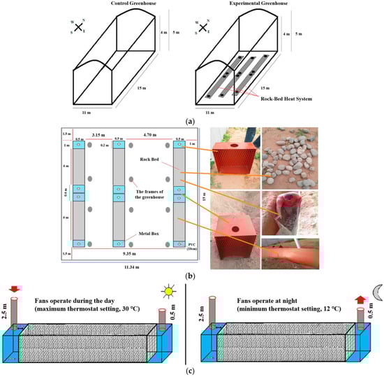
Figure 31.
The schematics of the proposed system by Bazgaou et al. [51]; (a) the considered greenhouses, (b) the details of the experimental setup, and (c) the performance of the proposed rock beds in two modes of charging (day) and discharging (night).
In a modified greenhouse dryer with an insulated north wall, Ahmad and Prakash [21] presented an experimental examination of various floor conditions, including a ground floor, concrete floor, gravel floor, and black-painted gravel floor. For different floor conditions, terms such as the heat utilization factor, heat loss factor, total heat transfer coefficient, and coefficient of diffusivity were determined. The experimental outcomes depicted that the painted gravel floor was found to have the most significant temperature differential between the room and outside air at 13 o’clock, followed by the gravel floor, concrete floor, and ground floor with differences of 27, 14,1, and 11.5 °C, respectively. Moreover, for the black-painted gravel floor, gravel floor, concrete floor, and ground floor, the growth in the percentage of the maximum room temperature compared to the maximum ambient temperature was observed to be 50.31, 46.15, 30.1, and 26.6%, respectively, at 13 o’clock. In conclusion, the black-painted gravel bed absorbed the maximum temperature.
Gourdo et al. [52] heated the ambient air in a Canarian-style greenhouse using a solar-energy-storing rock bed to maintain the ideal plant-growing environment. This device stores excess heat from the greenhouse during the day and releases it at night. The results of the experimental measures showed that the interior air temperature of the greenhouse with the rock bed was, at night, 3 °C higher and, during the day, 1.9 °C lower than that of a typical greenhouse. The solar energy storage greenhouse naturally had higher relative humidity during the day and lower relative humidity at night since it was heated during the day and cooled during the night. Additionally, this method positively impacted tomato yield, which grew by 22% compared to a traditional greenhouse. Throughout the night, the recommended technology raised the temperature in the greenhouse by 3 °C above that of a conventional greenhouse and 4.7 °C over that of the outside. Additionally, the suggested remedy lowered the experimental greenhouse’s air temperature by 3 °C outside and 1.9 °C within the traditional greenhouse. The schematics of the proposed system by Gourdo et al. [52] are demonstrated in Figure 32.
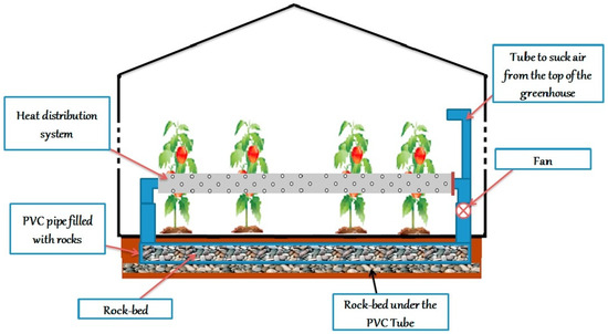
Figure 32.
The schematics of the proposed system by Gourdo et al. [52].
Bazgaou et al. [53] investigated and addressed the performance of combining two systems—a water-filled passive solar system and a rock bed TES system—to heat a Canarian greenhouse. In the Mediterranean region, thermal solar energy storage and reuse is crucial for greenhouse heating throughout the winter. The extra thermal energy in the greenhouse was kept for use during the colder months by storing it in the water and the rock bed. Two Canarian-style greenhouses were used for the experiment; one had a combined heating system (which included water storage and a rock bed as SHTES devices), while the other did not. The aforementioned greenhouses were located in the southern Moroccan province of Souss-Massa. The findings illustrate that utilizing the proposed combined heating system can augment the indoor air temperature during nighttime by 3–5 °C on clear days and 2–3 °C on cloudy or rainy days, with consistent effects (lower fluctuations) throughout the winter season. Moreover, overnight, the relative humidity of the air in the heated greenhouse decreased by 10–15%.
Moreover, on clear days, this heating system raised the substrate temperature by 4 °C; on cloudy or rainy days, it raised it by 3 °C at night. Finally, the greenhouse with the proposed heating experienced exceptionally robust plant growth, resulting in a substantial 49% increase in tomato yield. In other words, this system’s thermal energy restoration meets a considerable portion of the greenhouse heating requirements. Additionally, implementing this heating system decreased the Tuta absoluta (serious pest of tomato crops) population growth within the heated greenhouse. Based on the presented economic evaluation, this approach proves highly advantageous and holds the potential to generate income for farmers. The schematics of the proposed system by Bazgaou et al. [53] are demonstrated in Figure 33.

Figure 33.
The schematics of the proposed system by Bazgaou et al. [53].
In another work, Bazgaou et al. [54] employed a solar heating cooling system (SHCS) using quartzitic sandstone as the thermal storage material to store and utilize the surplus air thermal energy (SATE) in greenhouse production. They tested the system’s heating and cooling capabilities during the winter. The difference between this work and their previous work [53] is that the new effort did not employ water tanks as a passive heating/cooling system in contrast to the earlier work [53]. Like their previous work, the system was located within the Souss-Massa region of Morocco. The findings revealed that, with fewer variations and fluctuations, the air temperature in the greenhouse with SHCS was higher than that of the simple one by around 3 °C at night and 6 °C during the day. In addition, the relative humidity dropped by 10% at night. The tomato yield was 1.74 kg·m−2 higher with SHCS than it was with regular production.
Piché et al. [55] concentrated on the possibilities for greenhouse farming in arctic regions (circumpolar territories). Their work considered a case study in Nunavik, Quebec’s northern Inuit region (the Kuujjuaq cooperative greenhouse). The primary issue with greenhouses in Nordic climes, particularly in winter, is the excessive temperature differential between day and night, inhibiting crop growth. In October 2018, they planned, constructed, and deployed a heat storage system to mitigate this thermal behaviour. Based on rock bed thermal inertia, the TES system is a hybrid of an active and a passive system. The schematics of the proposed system by Piché et al. [55] are demonstrated in Figure 34.
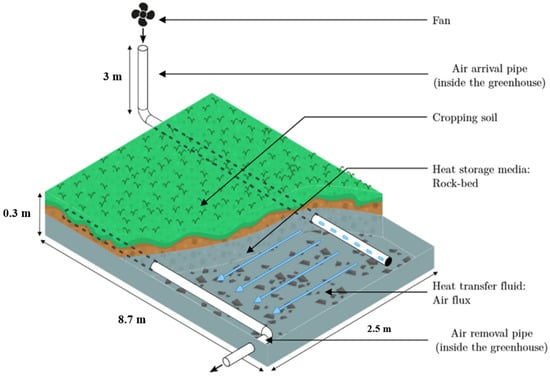

Figure 34.
The schematics of the proposed system by Piché et al. [55].
In the active system, the rocks lie under the cultivated soil. Therefore, no ground excavation is required. Based on the Tichelmann principle, the active system’s air distribution system arranges the pipes so that air flows through each segment of the storage system for the same period.
Each of the four sections that made up the greenhouse had a separate system known as a “caisson”. Roughly 1 × 10⁴ kg of rocks with grain sizes ranging from 0.01 m to 0.05 m are included in each caisson. A fan at the top of the greenhouse draws air into the system and then disseminates it through a blocked pipe with a perforation in its embedded section. The air is collected by another perforated tube after exiting the caisson and released into the bottom section of the greenhouse.
The ventilation mechanism keeps the warm air at the top of the greenhouse from being expelled outdoors throughout the day and blows it into the caisson’s colder rocks. This is the TES system’s charging phase, which warms the rocks and simultaneously cools the greenhouse air. In contrast, by forcing air into the heated rocks at night, the operation will warm the air within the greenhouse. In addition to this convective heat transfer, conductive heat transfer from the rock stock keeps the cultivated soil at an ideal temperature for plant growth. Lastly, it is essential to note that the active TES system is connected to a passive storage system consisting of a concrete floor slab and rocks between 0.05 and 0.2 m enclosed in gabion baskets.
Their outcomes presented that the first need to reduce the difference in temperature between day and night inside the greenhouse is fulfilled by the combination of passive and active thermoelectric sensors. It is possible to keep the lowest temperature above 10 °C for most of the growth season using the suggested TES system. Considering the amount of power used for both the charging and discharging phases, the system’s coefficient of performance (COP) ranges from 1.4 to 3. It should be mentioned that during the start of the growth season, the stored energy makes up between 6.2% and 10.6% of the solar energy available within the greenhouse.
Bazgaou et al. [56] employed computational fluid dynamics (CFD) models to simulate the microclimate in a greenhouse with a rock bed heating system. Crop rows and rock bed blocks were deemed porous mediums because of their dynamic and thermal properties. The model’s correctness was validated by comparing simulated and experimental greenhouse climatic parameter data. The model’s ability to forecast temperature, humidity, and air velocity fields in the greenhouse and rock bed systems was proved during energy storage and restitution. This numerical model adequately duplicated the thermal, dynamic, and hygric fields. The widely used commercial CFD code Fluent module from ANSYS was utilized to model the microclimate in the greenhouse, which was equipped with a rock bed heating system. According to the CFD results, the maximum humidity values were recorded in the bottom portion of the greenhouse.
In contrast, the lowest values were reported in the top section of the greenhouse. From the top to the bottom of the greenhouse, these values ranged between 20% and 36%. The schematic of the proposed computational domain and temperature contour as one of their outcomes are presented in Figure 35.
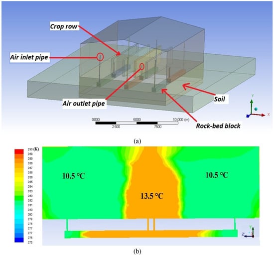
Figure 35.
(a) The schematics of the proposed system by Bazgaou et al. [56], and (b) the slice temperature contour inside the proposed computational domain.
A summary of previous works using rock beds as a thermal battery, a SHTES system, and a preconditioning system (both temperature and humidity regulator) is given in Table 2. It should be noted that the references in this table are listed in chronological order. Because the suggested system in this PhD thesis proposal is a system of injection and sucking of greenhouse moist air into the rock bed to store and release the sun’s thermal energy as storable energy in the rock bed, a column in this table is considered that shows whether or not the proposed injection/sucking system is used in the reference. Future chapters will offer a more detailed description of how this strategy is used in the proposed system.
Table 2.
The literature review of previous work concerning the application of rock beds in greenhouses.
Table 2 illustrates that according to the best knowledge of the authors, Bouhdjar et al. [48], in 1996, was the first work in which the idea of coupling a rock bed–greenhouse system with an injection/sucking system was presented. Furthermore, it can be seen that, generally, the porosity of the employed rock bed in the greenhouse is about 0.4, and the range of the average diameter of the rocks is 25–100 mm.
Based on the details described in Table 2, it can be observed that the majority of the work was conducted experimentally, except for one paper (Bazgaou et al. [56]), which was conducted numerically (CFD). It makes sense that a new system’s effectiveness and performance in a particular application should be assessed in a lab to ascertain the difficulties and challenges that may arise during operation. However, even though Bouhdjar et al. [48] introduced the suggested system around 27 years ago, numerical approaches have not been employed in the proposed rock bed–greenhouse system with a humid air injection/suction mechanism. In contrast, numerical methods are effective techniques for optimising thermal systems to increase performance.
According to the literature review presented in Section 2.2 and the details listed in Table 2, it can be concluded that employing a rock bed as a thermal battery, an SHTES, a humidifier/dehumidifier, or even a pre-conditioner could be a very effective and promising method to improve the efficiency of greenhouses during cold seasons, particularly in regions with harsh winters.
Table 2 details the relevant work in applying rock beds in greenhouses. Accordingly, it can be seen that most of the work was experimental, except for one study (Bazgaou et al. [56]) that used numerical methods (CFD). It makes sense to evaluate a new system’s efficacy and performance in a specific lab application to identify any potential problems or obstacles. Nevertheless, although Bouhdjar et al. [48] presented the recommended method around 28 years ago, the proposed rock bed–greenhouse system with a humid air injection/suction mechanism was not analyzed in detail by numerical techniques. Numerical approaches, on the other hand, are helpful strategies for improving thermal systems’ performance.
Moreover, according to Table 2, the rock bed’s considered porosity range is 0.33–0.49. It is worth mentioning that researchers mostly used a porosity of 0.35. Also, the rock bed’s particle diameter range is 0.25–10 cm.
A rock bed is a porous region of stone grains arranged randomly and irregularly and has a variety of geometries and shapes. One of the challenging issues in fluid dynamics is the flow passage through a heterogeneous porous region, a subject of ongoing research. If phase change (condensation and evaporation) is added to this problem, it contains more complications. With the passage of moist air inside the porous area, depending on the bed’s temperature and the functional state type (charge or discharge), the humid air can condense or evaporate, and its moisture content increases or decreases.
Therefore, it can be realized that fluid flow and heat transfer in a rock bed with phase change are complex. This process has been investigated separately in previously published works but has not been studied and analyzed practically for a rock bed coupled with a greenhouse. Moreover, in the proposed system, some injection and suction pipes are embedded in the bed to store and release the solar energy (extra part) in the rock bed. According to the details presented in Table 2, it can be seen that the previous works did not focus on the design of the arrangement and the geometry of these pipes, which are perforated. There are various geometrical factors related to these pipes which affect the performance of the rock bed.
2.3. LHTES and SHTES Systems Simultaneously in Greenhouses
Vadiee et al. [9] employed TRNSYS to create a theoretical model for energy analysis. They provided a qualitative study of the economics of a TES-equipped closed greenhouse. The peak load was controlled by a PCM or SCW daily storage system, while a BTES system handled seasonal storage. The primary function of BTES is to retain low-temperature heat; hence, a heat pump is needed to supply heat at the right temperature. The idea behind seasonal storage is to optimize solar energy utilization. Thus, seasonal and/or daily TES methods must be employed to collect and store excess sensible and latent heat. Later, this extra heat can be used to meet the greenhouse’s thermal load. Seasonal storage is the most common application for UTES. To meet daily demands and peak loads, a short-term storage system such as PCM storage or stratified chilled water (SCW) storage may be employed. The findings of the economic feasibility evaluation suggested that the concept has the potential to become cost-effective. Given the seasonal TES systems, the significant investment in the closed greenhouse idea might be repaid in 7–8 years from savings on supplemental fossil fuel. However, if the base load is used as the design load rather than the peak load, the payback time can be decreased to 5 years. In this instance, a short-term TES is required to cover the hourly peak demands. The schematics of the proposed system by Vadiee et al. [9] are shown in Figure 36.

Figure 36.
(a) The conceptual aspects of a closed greenhouse in heating and cooling modes (without considering the heat pump cycle) and (b) various layouts of the proposed TES systems in the proposed greenhouse by Vadiee et al. [9].
3. Conclusions
A viable way to improve agricultural operations’ sustainability and energy efficiency is to deploy TES devices as thermal batteries in greenhouses. By preserving ideal growth conditions, TES systems can lower interior temperature fluctuations, decrease the need for heating and cooling, and increase crop yields. By reducing the dependency on fossil fuels, integrating TES with renewable energy sources even further improves its environmental advantages. To fully realize the promise of TES in greenhouse applications, future research should concentrate on refining TES materials, enhancing system designs, and evaluating the long-term environmental and economic effects. In this review work, various dimensions and methods of using TES systems inside greenhouses have been examined, and the achievements of previous related works have been evaluated:
- The promising results obtained from previous works, which show that TES systems should be considered one of the main components of greenhouses today, can be mentioned as an attainment of the present work.
- Most studies employing a PCM in greenhouses as the latent heat type of TES systems have been conducted experimentally, with fewer statistical or analytical investigations. This issue might be viewed as a research gap that should be addressed in future studies.
- Generally, six types of PCMs were employed in greenhouses as TES. These systems used pure paraffin, calcium chloride hexahydrate (CaCl2.6H2O), GH-20, AC27, RT types (RT12, RT15, and RT18HC), and shape-stabilized PCMs. It can be concluded that paraffin is the most commonly used PCM.
- A very effective and promising way to increase greenhouse efficiency during cold seasons, especially in areas with harsh winters, is to use a rock bed as a thermal battery, an SHTES, a humidifier/dehumidifier, or even a pre-conditioner.
- Most of the previous works presented by researchers in the field of using rock beds for the thermal management of greenhouses were conducted experimentally, and only one numerical work was employed for the thermal analysis of the bed.
- Bouhdjar et al. [48] first presented the most efficient greenhouse–rock bed coupled system design in 1996, in which the humid air injection/suction mechanism was utilized for charging/discharging modes. Other researchers later used this method. However, no detailed analysis has yet been conducted to optimize its performance.
- The range of rock bed porosity considered in the previous works is 0.33–0.49. It is worth mentioning that researchers mostly used a porosity of 0.35. Also, the rock bed’s particle diameter range is 0.25–10 cm.
The present study also presents research gaps in this field. Most of the work was carried out experimentally, and indeed, to achieve a correct understanding of the phenomena in the system, more accurate methods such as computational fluid dynamics methods should be used; this could be an excellent suggestion for future works.
Author Contributions
Conceptualization, S.S.M.A., L.A. and S.P.; formal analysis, S.S.M.A.; investigation, S.S.M.A.; resources, S.S.M.A., L.A. and S.P.; data curation, S.S.M.A.; writing—original draft preparation, S.S.M.A.; writing—review and editing, S.S.M.A., L.A. and S.P.; supervision, L.A. and S.P.; project administration, L.A. and S.P.; funding acquisition, L.A. and S.P. All authors have read and agreed to the published version of the manuscript.
Funding
NSERC Alliance (ALLRP 565628-21) and Innovéé (PSO-2104) in collaboration with Hydro-Québec, Ferme des Quatre Temps, Serres Royales, Abri Végétal, Aerogeothermik Inc., Copeland Canada Inc., Atis Énergie, and CETAB+.
Data Availability Statement
Not applicable.
Conflicts of Interest
The authors declare no conflicts of interest.
References
- Badji, A.; Benseddik, A.; Bensaha, H.; Boukhelifa, A.; Hasrane, I. Design, technology, and management of greenhouse: A review. J. Clean. Prod. 2022, 373, 133753. [Google Scholar] [CrossRef]
- Syed, A.M.; Hachem, C. Review of construction; geometry; heating, ventilation, and air-conditioning; and indoor climate requirements of agricultural greenhouses. J. Biosyst. Eng. 2019, 44, 18–27. [Google Scholar] [CrossRef]
- Teitel, M.; Montero, J.I.; Baeza, E.J. Greenhouse design: Concepts and trends. In International Symposium on Advanced Technologies and Management Towards Sustainable Greenhouse Ecosystems Greensys2011; ISHS: Athens, Greece, 2011; Volume 952, pp. 605–620. [Google Scholar] [CrossRef]
- Cuce, E.; Harjunowibowo, D.; Cuce, P.M. Renewable and sustainable energy saving strategies for greenhouse systems: A comprehensive review. Renew. Sustain. Energy Rev. 2016, 64, 34–59. [Google Scholar] [CrossRef]
- Singh, P.; Gaur, M.K. Heat transfer analysis of hybrid active greenhouse solar dryer attached with evacuated tube solar collector. Sol. Energy 2021, 224, 1178–1192. [Google Scholar] [CrossRef]
- Prakash, O.; Kumar, A. Thermal performance evaluation of modified active greenhouse dryer. J. Build. Phys. 2014, 37, 395–402. [Google Scholar] [CrossRef]
- Salinas, I.; Hueso, J.J.; Cuevas, J. Active Control of Greenhouse Climate Enhances Papaya Growth and Yield at an Affordable Cost. Agronomy 2021, 11, 378. [Google Scholar] [CrossRef]
- Nishad, S.; Krupa, I. Phase change materials for thermal energy storage applications in greenhouses: A review. Sustain. Energy Technol. Assess. 2022, 52, 102241. [Google Scholar] [CrossRef]
- Vadiee, A.; Martin, V. Thermal energy storage strategies for effective closed greenhouse design. Appl. Energy 2013, 109, 337–343. [Google Scholar] [CrossRef]
- Gorjian, S.; Ebadi, H.; Najafi, G.; Singh Chandel, S.; Yildizhan, H. Recent advances in net-zero energy greenhouses and adapted thermal energy storage systems. Sustain. Energy Technol. Assess. 2021, 43, 100940. [Google Scholar] [CrossRef]
- Paksoy, H.Ö.; Beyhan, B. Thermal energy storage (TES) systems for greenhouse technology. In Advances in Thermal Energy Storage Systems; Woodhead Publishing: Cambridge, UK, 2015; pp. 533–548. ISBN 978-1-78242-088-0. [Google Scholar]
- Teggar, M.; Ajarostaghi, S.S.M.; Yıldız, Ç.; Arıcı, M.; Ismail, K.A.R.; Niyas, H.; Lino, F.A.M.; Mert, M.S.; Khalid, M. Performance enhancement of latent heat storage systems by using extended surfaces and porous materials: A state-of-the-art review. J. Energy Storage 2021, 44, 103340. [Google Scholar] [CrossRef]
- Rocha, T.T.M.; Teggar, M.; Trevizoli, P.V.; De Oliveira, R.N. Potential of latent thermal energy storage for performance improvement in small-scale refrigeration units: A review. Renew. Sustain. Energy Rev. 2023, 187, 113746. [Google Scholar] [CrossRef]
- Jouhara, H.; Żabnieńska-Góra, A.; Khordehgah, N.; Ahmad, D.; Lipinski, T. Latent thermal energy storage technologies and applications: A review. Int. J. Thermofluids 2020, 5–6, 100039. [Google Scholar] [CrossRef]
- Alva, G.; Lin, Y.; Fang, G. An overview of thermal energy storage systems. Energy 2018, 144, 341–378. [Google Scholar] [CrossRef]
- Sarbu, I.; Sebarchievici, C. A Comprehensive Review of Thermal Energy Storage. Sustainability 2018, 10, 191. [Google Scholar] [CrossRef]
- Chen, C.; Yu, N.; Yang, F.; Mahkamov, K.; Han, F.; Li, Y.; Ling, H. Theoretical and experimental study on selection of physical dimensions of passive solar greenhouses for enhanced energy performance. Sol. Energy 2019, 191, 46–56. [Google Scholar] [CrossRef]
- Ajarostaghi, S.S.M.; Mousavi, S.S. Solar energy conversion technologies: Principles and advancements. In Solar Energy Advancements in Agriculture and Food Production Systems; Academic Press: New York, NY, USA, 2022; pp. 29–76. [Google Scholar] [CrossRef]
- Zaboli, M.; Saedodin, S.; Ajarostaghi, S.S.M.; Karimi, N. Recent progress on flat plate solar collectors equipped with nanofluid and turbulator: State of the art. Environ. Sci. Pollut. Res. 2023, 30, 109921–109954. [Google Scholar] [CrossRef]
- Kazemi Moghadam, H.; Mousavi Ajarostaghi, S.S.; Poncet, S. Numerical modeling of an innovative arc shape rib based solar air heater. Proc. Inst. Mech. Eng. Part C J. Mech. Eng. Sci. 2021, 235, 7992–8012. [Google Scholar] [CrossRef]
- Ahmad, A.; Prakash, O. Thermal analysis of north wall insulated greenhouse dryer at different bed conditions operating under natural convection mode. Environ. Prog. Sustain. Energy 2019, 38, e13257. [Google Scholar] [CrossRef]
- Liu, X.; Li, Y.; Liu, A.; Yue, X.; Li, T. Effect of North Wall Materials on the Thermal Environment in Chinese Solar Greenhouse (Part A: Experimental Researches). Open Phys. 2019, 17, 752–767. [Google Scholar] [CrossRef]
- Chauhan, P.S.; Kumar, A. Heat transfer analysis of north wall insulated greenhouse dryer under natural convection mode. Energy 2017, 118, 1264–1274. [Google Scholar] [CrossRef]
- Berroug, F.; Lakhal, E.K.; El Omari, M.; Faraji, M.; El Qarnia, H. Thermal performance of a greenhouse with a phase change material north wall. Energy Build. 2011, 43, 3027–3035. [Google Scholar] [CrossRef]
- Ling, H.; Chen, C.; Guan, Y.; Wei, S.; Chen, Z.; Li, N. Active heat storage characteristics of active–passive triple wall with phase change material. Sol. Energy 2014, 110, 276–285. [Google Scholar] [CrossRef]
- Ling, H.; Chen, C.; Wei, S.; Guan, Y.; Ma, C.; Xie, G.; Li, N.; Chen, Z. Effect of phase change materials on indoor thermal environment under different weather conditions and over a long time. Appl. Energy 2015, 140, 329–337. [Google Scholar] [CrossRef]
- Chen, C.; Ling, H.; Zhai, Z.; Li, Y.; Yang, F.; Han, F.; Wei, S. Thermal performance of an active-passive ventilation wall with phase change material in solar greenhouses. Appl. Energy 2018, 216, 602–612. [Google Scholar] [CrossRef]
- Guan, Y.; Meng, Q.; Ji, T.; Hu, W.; Li, W.; Liu, T. Experimental study of the thermal characteristics of a heat storage wall with micro-heat pipe array (MHPA) and PCM in solar greenhouse. Energy 2023, 264, 126183. [Google Scholar] [CrossRef]
- Öztürk, H.H. Experimental evaluation of energy and exergy efficiency of a seasonal latent heat storage system for greenhouse heating. Energy Convers. Manag. 2005, 46, 1523–1542. [Google Scholar] [CrossRef]
- Benli, H.; Durmuş, A. Performance analysis of a latent heat storage system with phase change material for new designed solar collectors in greenhouse heating. Sol. Energy 2009, 83, 2109–2119. [Google Scholar] [CrossRef]
- Kooli, S.; Bouadila, S.; Lazaar, M.; Farhat, A. The effect of nocturnal shutter on insulated greenhouse using a solar air heater with latent storage energy. Sol. Energy 2015, 115, 217–228. [Google Scholar] [CrossRef]
- Bouadila, S.; Kooli, S.; Skouri, S.; Lazaar, M.; Farhat, A. Improvement of the greenhouse climate using a solar air heater with latent storage energy. Energy 2014, 64, 663–672. [Google Scholar] [CrossRef]
- Ziapour, B.M.; Hashtroudi, A. Performance study of an enhanced solar greenhouse combined with the phase change material using genetic algorithm optimization method. Appl. Therm. Eng. 2017, 110, 253–264. [Google Scholar] [CrossRef]
- Baddadi, S.; Bouadila, S.; Ghorbel, W.; Guizani, A. Autonomous greenhouse microclimate through hydroponic design and refurbished thermal energy by phase change material. J. Clean. Prod. 2019, 211, 360–379. [Google Scholar] [CrossRef]
- Joshua, D.R.; Zachariah, R.; Anumod, D.M. Performance improvement in mixed-mode solar dryer with addition of paraffin-based thermal energy storage. J. Green Eng. 2020, 10, 1403–1418. [Google Scholar]
- Azaizia, Z.; Kooli, S.; Hamdi, I.; Elkhal, W.; Guizani, A.A. Experimental study of a new mixed mode solar greenhouse drying system with and without thermal energy storage for pepper. Renew. Energy 2020, 145, 1972–1984. [Google Scholar] [CrossRef]
- Shimpy; Kumar, M.; Kumar, A.; Sahdev, R.K.; Manchanda, H. Comparison of groundnut drying in simple and modified natural convection greenhouse dryers: Thermal, environmental and kinetic analyses. J. Stored Prod. Res. 2022, 98, 101990. [Google Scholar] [CrossRef]
- Yang, R.; Li, D.; Arıcı, M.; Wang, B.; Wu, Y.; Ma, Y.; Yang, X. Photothermal performance of plastic greenhouse embedded with phase change materials in translucent envelopes: A dynamic experimental study. J. Energy Storage 2023, 58, 106375. [Google Scholar] [CrossRef]
- Llorach-Massana, P.; Peña, J.; Rieradevall, J.; Montero, J.I. Analysis of the technical, environmental and economic potential of phase change materials (PCM) for root zone heating in Mediterranean greenhouses. Renew. Energy 2017, 103, 570–581. [Google Scholar] [CrossRef]
- Xu, W.; Guo, H.; Ma, C. An active solar water wall for passive solar greenhouse heating. Appl. Energy 2022, 308, 118270. [Google Scholar] [CrossRef]
- Wang, J.; Qu, M.; Zhao, S.; Ma, C.; Song, W. New insights into the scientific configuration of a sheet heating system applied in Chinese solar greenhouse. Appl. Therm. Eng. 2023, 219, 119448. [Google Scholar] [CrossRef]
- Javadi, H.; Mousavi Ajarostaghi, S.S.; Rosen, M.A.; Pourfallah, M. Performance of ground heat exchangers: A comprehensive review of recent advances. Energy 2019, 178, 207–233. [Google Scholar] [CrossRef]
- Zhang, L.; Xu, P.; Mao, J.; Tang, X.; Li, Z.; Shi, J. A low cost seasonal solar soil heat storage system for greenhouse heating: Design and pilot study. Appl. Energy 2015, 156, 213–222. [Google Scholar] [CrossRef]
- Awani, S.; Kooli, S.; Chargui, R.; Guizani, A. Numerical and experimental study of a closed loop for ground heat exchanger coupled with heat pump system and a solar collector for heating a glass greenhouse in north of Tunisia. Int. J. Refrig. 2017, 76, 328–341. [Google Scholar] [CrossRef]
- Luo, J.; Li, A.; Ma, X.; Pei, K. Stabilization of the temperature in a greenhouse using a Geothermal-Battery-Energy-Storage (GBES) system. Appl. Therm. Eng. 2023, 223, 120029. [Google Scholar] [CrossRef]
- Li, H.; Nagano, K.; Lai, Y.; Shibata, K.; Fujii, H. Evaluating the performance of a large borehole ground source heat pump for greenhouses in northern Japan. Energy 2013, 63, 387–399. [Google Scholar] [CrossRef]
- Boughanmi, H.; Lazaar, M.; Bouadila, S.; Farhat, A. Thermal performance of a conic basket heat exchanger coupled to a geothermal heat pump for greenhouse cooling under Tunisian climate. Energy Build. 2015, 104, 87–96. [Google Scholar] [CrossRef]
- Bouhdjar, A.; Belhamel, M.; Belkhiri, F.E.; Boulbina, A. Performance of sensible heat storage in a rockbed used in a tunnel greenhouse. Renew. Energy 1996, 9, 724–728. [Google Scholar] [CrossRef]
- Kürklü, A.; Bilgin, S.; Özkan, B. A study on the solar energy storing rock-bed to heat a polyethylene tunnel type greenhouse. Renew. Energy 2003, 28, 683–697. [Google Scholar] [CrossRef]
- Jain, D. Modeling the performance of greenhouse with packed bed thermal storage on crop drying application. J. Food Eng. 2005, 71, 170–178. [Google Scholar] [CrossRef]
- Bazgaou, A.; Fatnassi, H.; Bouhroud, R.; Gourdo, L.; Ezzaeri, K.; Tiskatine, R.; Demrati, H.; Wifaya, A.; Bekkaoui, A.; Aharoune, A.; et al. An experimental study on the effect of a rock-bed heating system on the microclimate and the crop development under canarian greenhouse. Sol. Energy 2018, 176, 42–50. [Google Scholar] [CrossRef]
- Gourdo, L.; Fatnassi, H.; Tiskatine, R.; Wifaya, A.; Demrati, H.; Aharoune, A.; Bouirden, L. Solar energy storing rock-bed to heat an agricultural greenhouse. Energy 2019, 169, 206–212. [Google Scholar] [CrossRef]
- Bazgaou, A.; Fatnassi, H.; Bouharroud, R.; Elame, F.; Ezzaeri, K.; Gourdo, L.; Wifaya, A.; Demrati, H.; Tiskatine, R.; Bekkaoui, A.; et al. Performance assessment of combining rock-bed thermal energy storage and water filled passive solar sleeves for heating Canarian greenhouse. Sol. Energy 2020, 198, 8–24. [Google Scholar] [CrossRef]
- Bazgaou, A.; Fatnassi, H.; Bouharroud, R.; Ezzaeri, K.; Gourdo, L.; Wifaya, A.; Demrati, H.; El Baamrani, H.; Idoum, A.; Bekkaoui, A.; et al. Efficiency assessment of a solar heating cooling system applied to the greenhouse microclimate. Mater. Today Proc. 2020, 24, 151–159. [Google Scholar] [CrossRef]
- Piché, P.; Haillot, D.; Gibout, S.; Arrabie, C.; Lamontagne, M.-A.; Gilbert, V.; Bédécarrats, J.-P. Design, construction and analysis of a thermal energy storage system adapted to greenhouse cultivation in isolated northern communities. Sol. Energy 2020, 204, 90–105. [Google Scholar] [CrossRef]
- Bazgaou, A.; Fatnassi, H.; Bouharroud, R.; Tiskatine, R.; Wifaya, A.; Demrati, H.; Bammou, L.; Aharoune, A.; Bouirden, L. CFD Modeling of the Microclimate in a Greenhouse Using a Rock Bed Thermal Storage Heating System. Horticulturae 2023, 9, 183. [Google Scholar] [CrossRef]
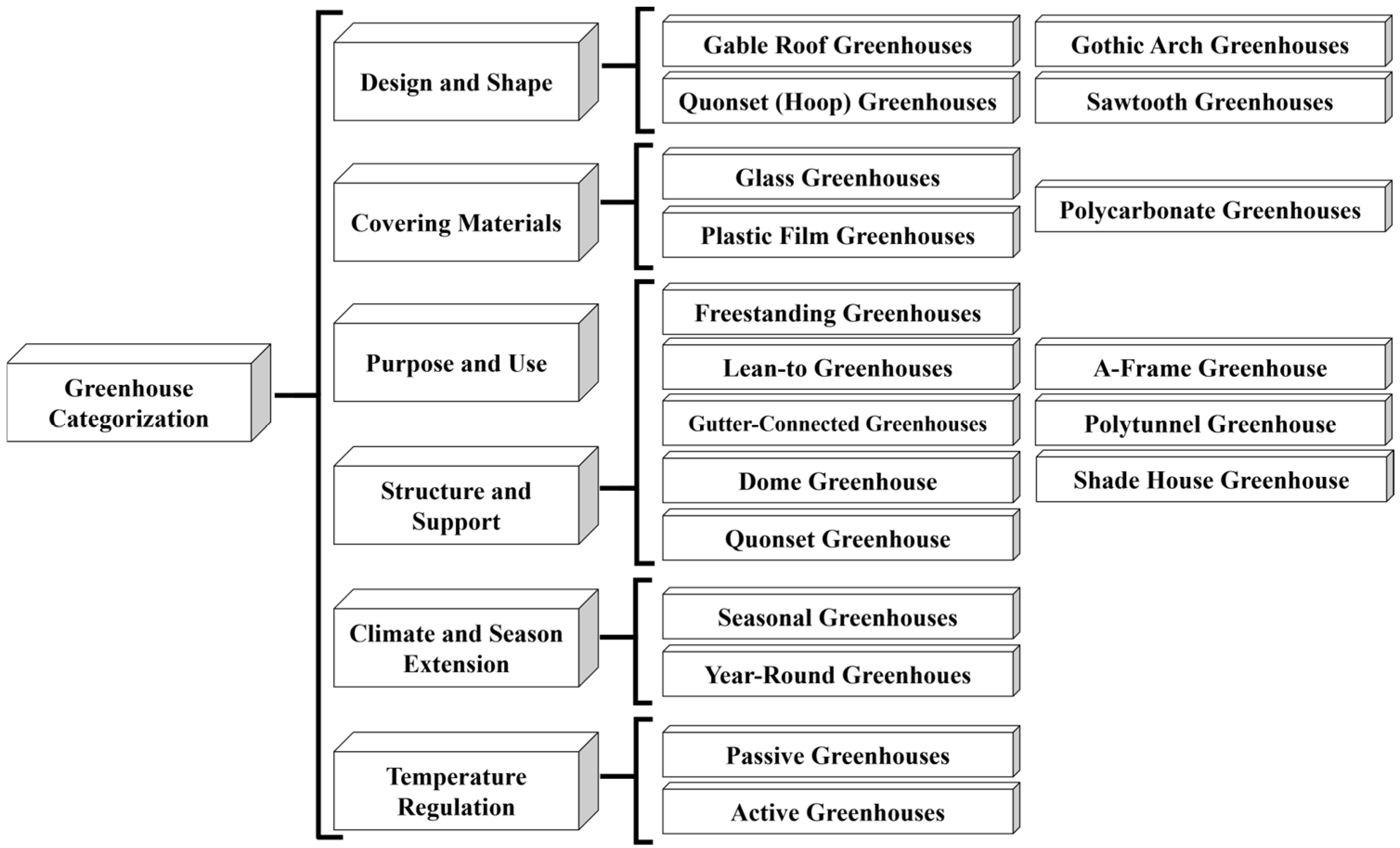
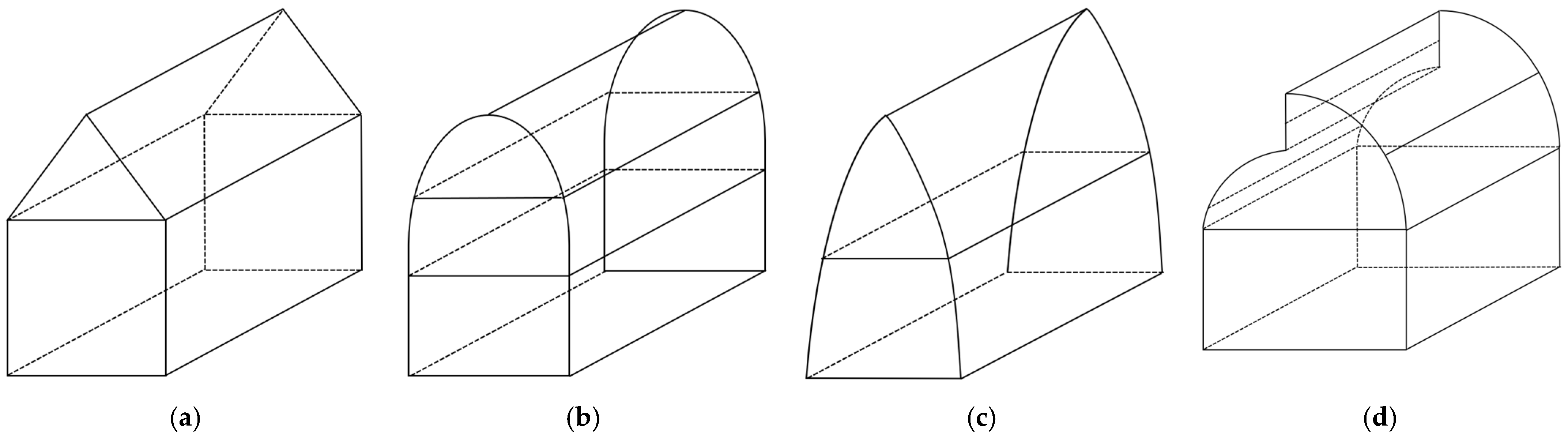
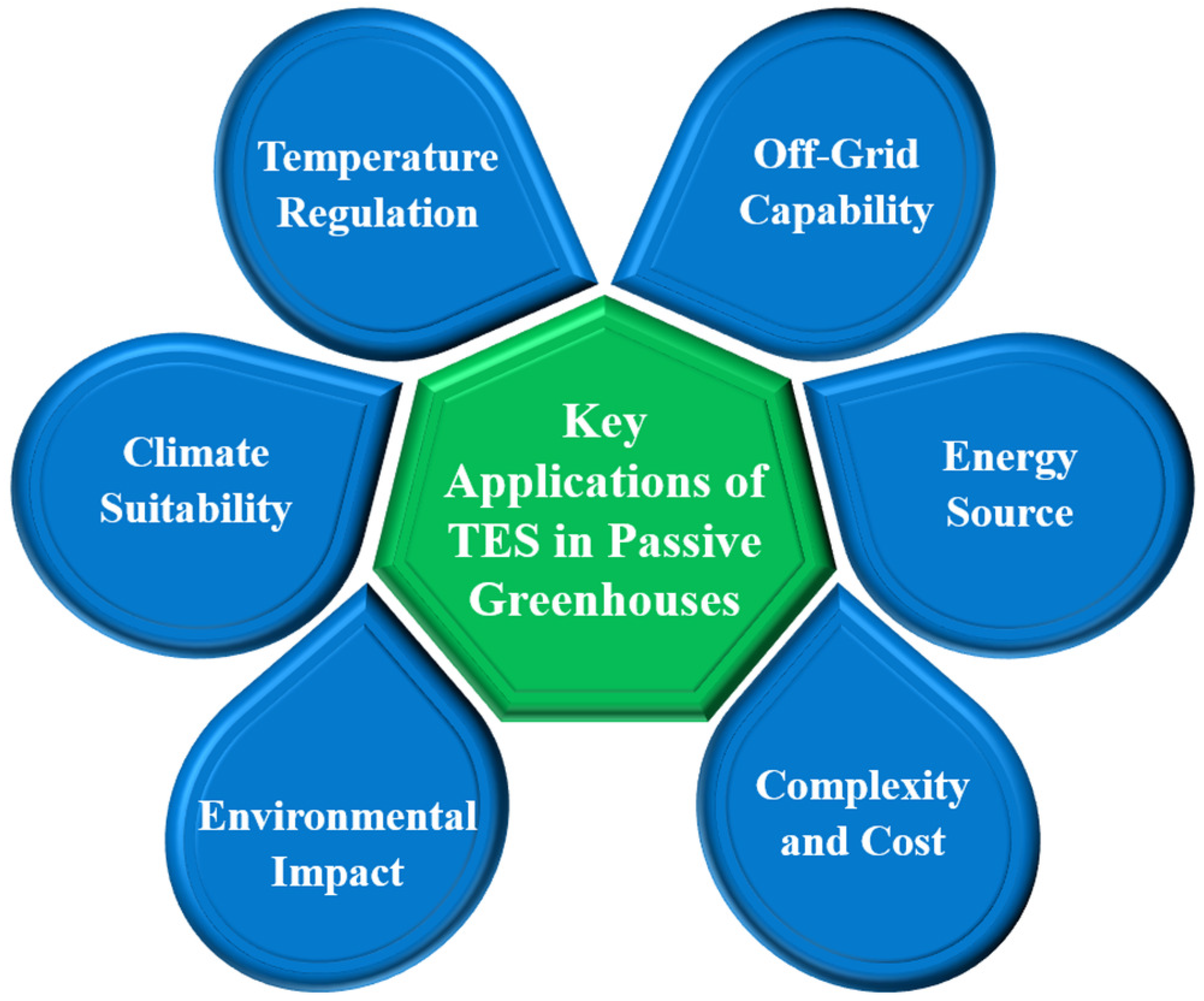

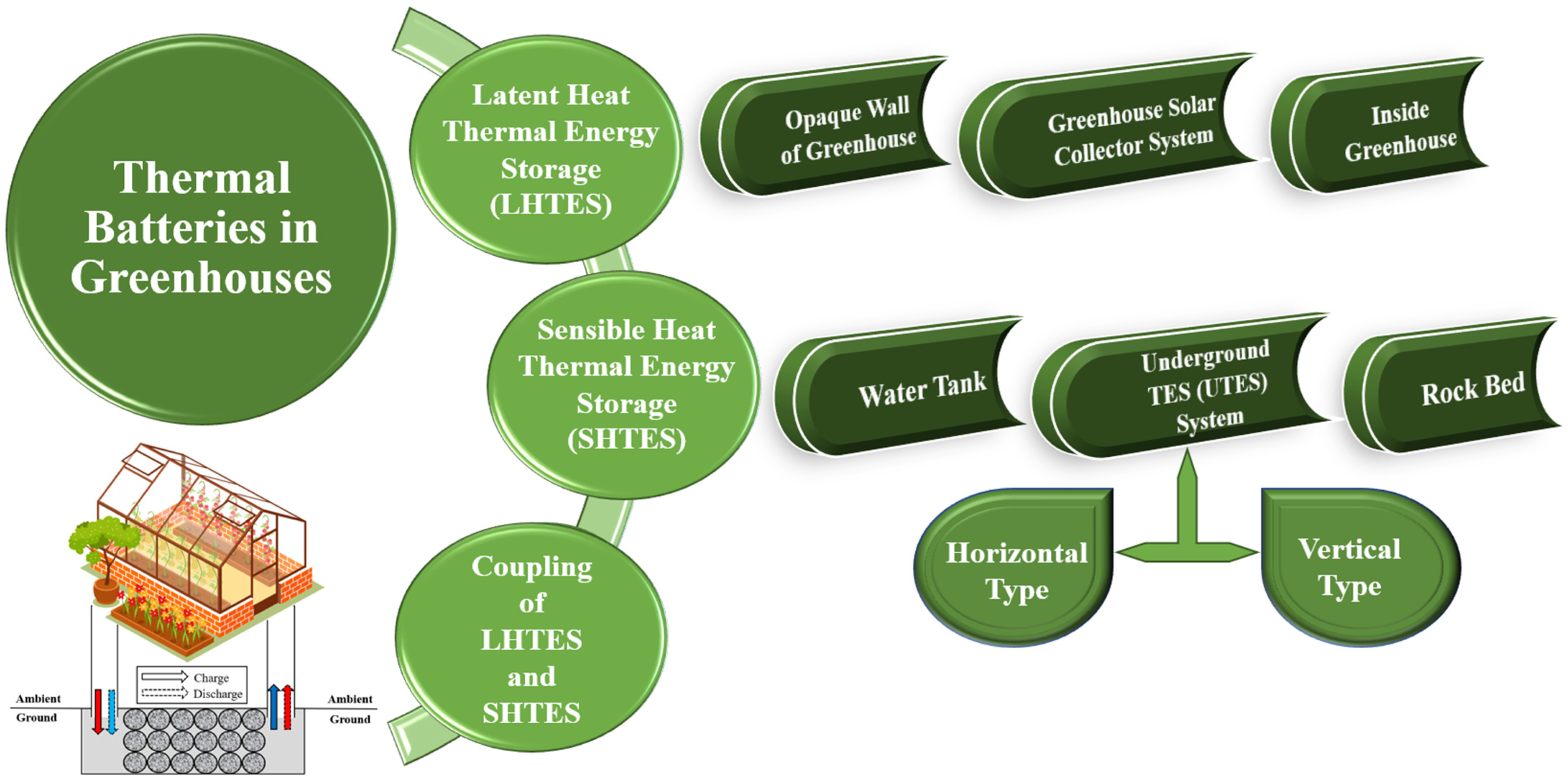
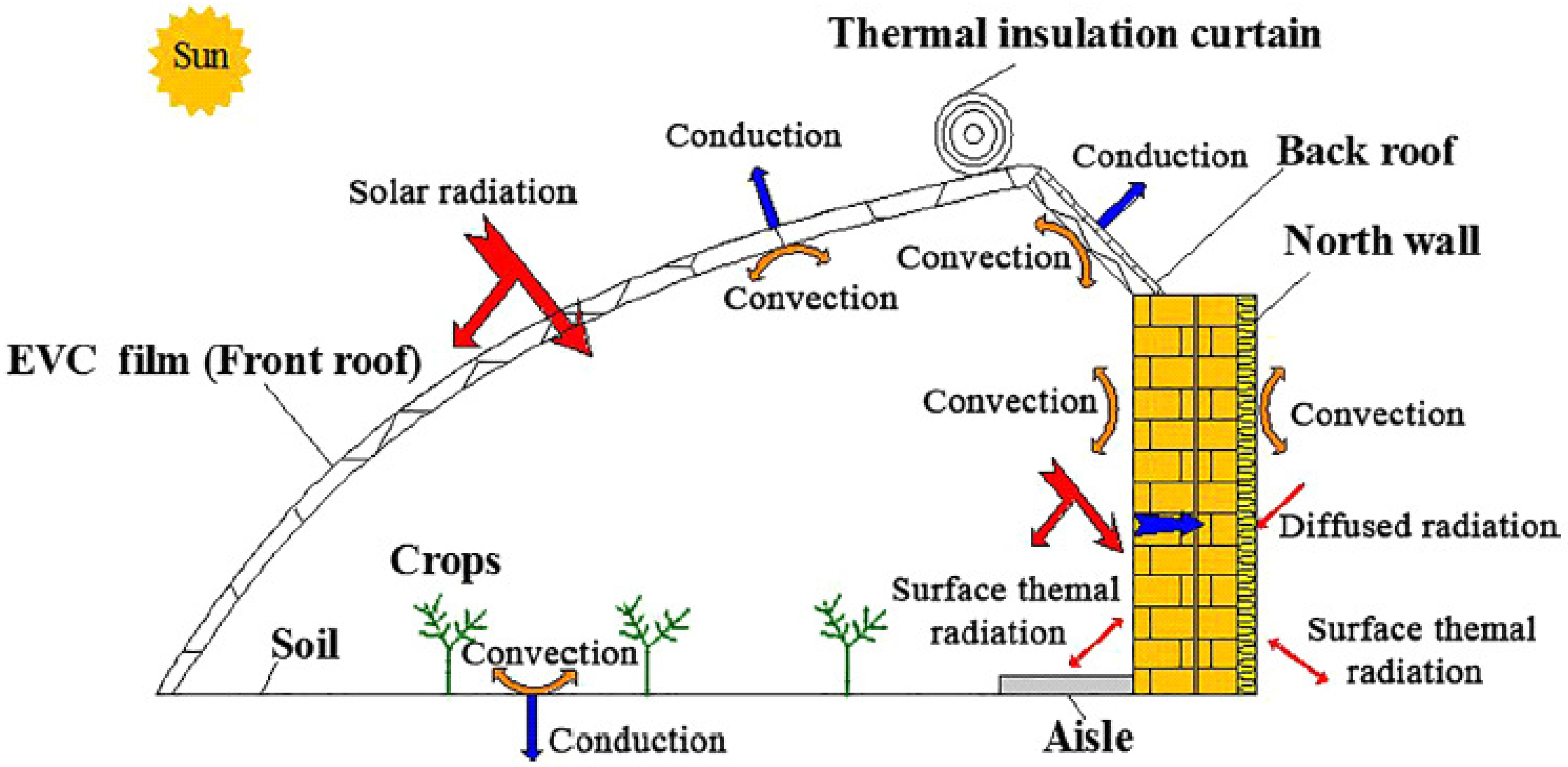
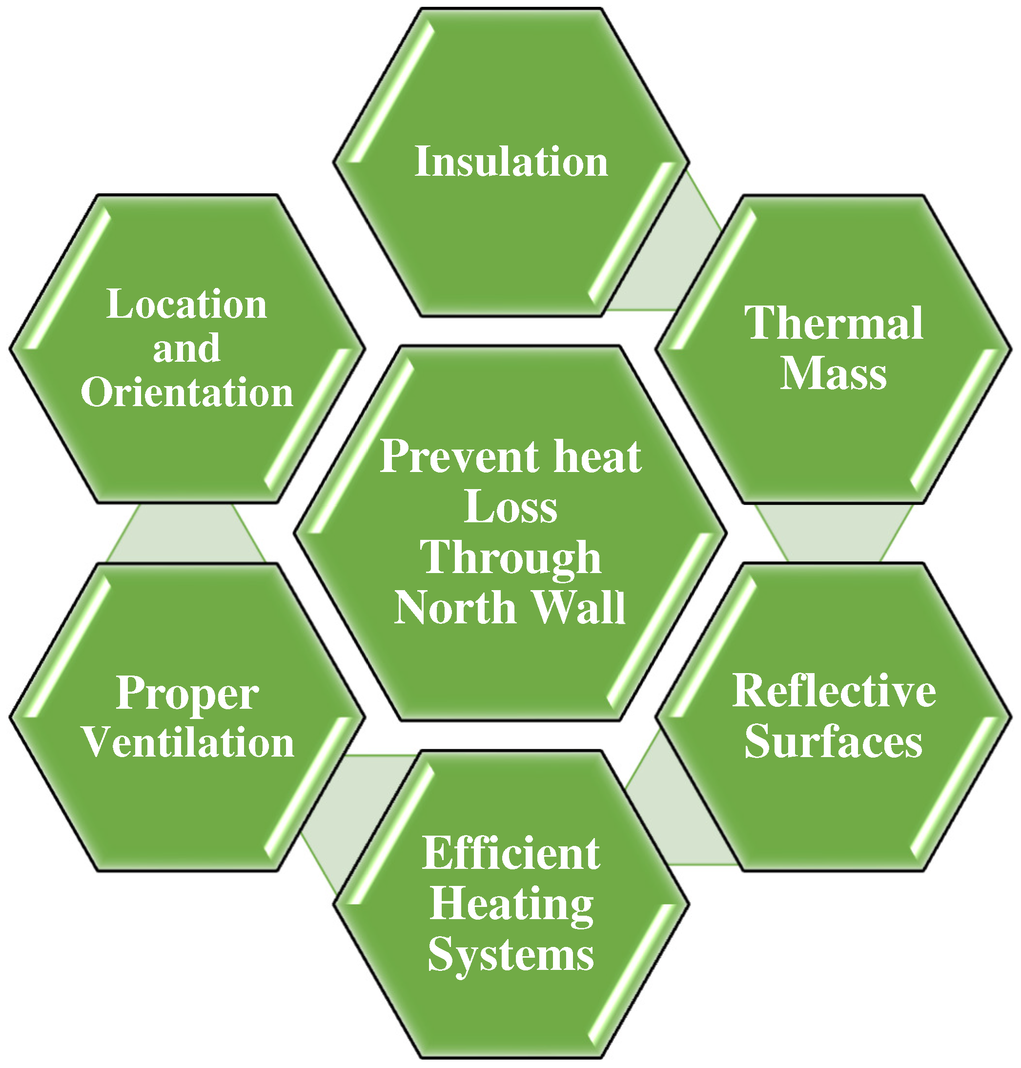
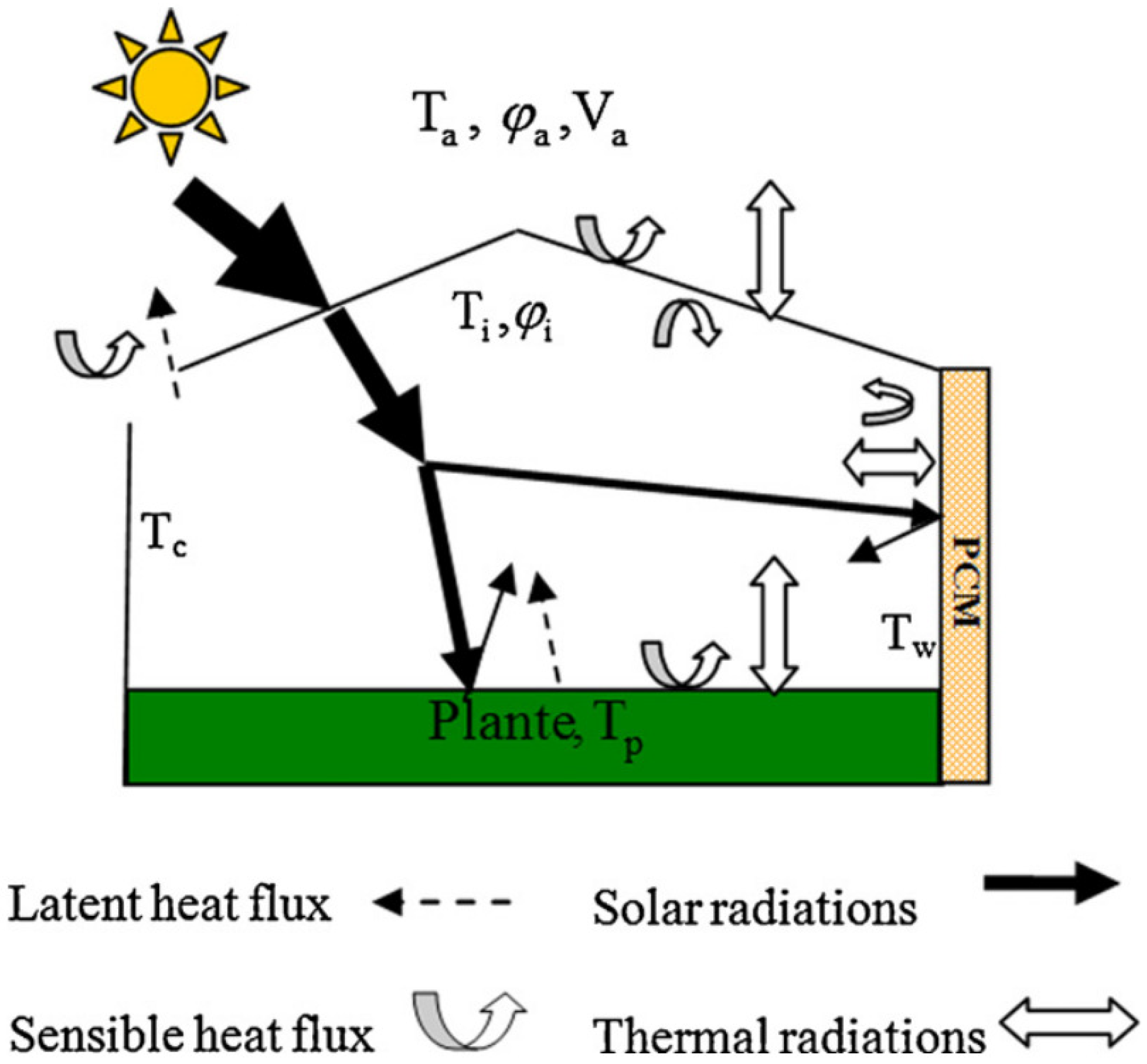

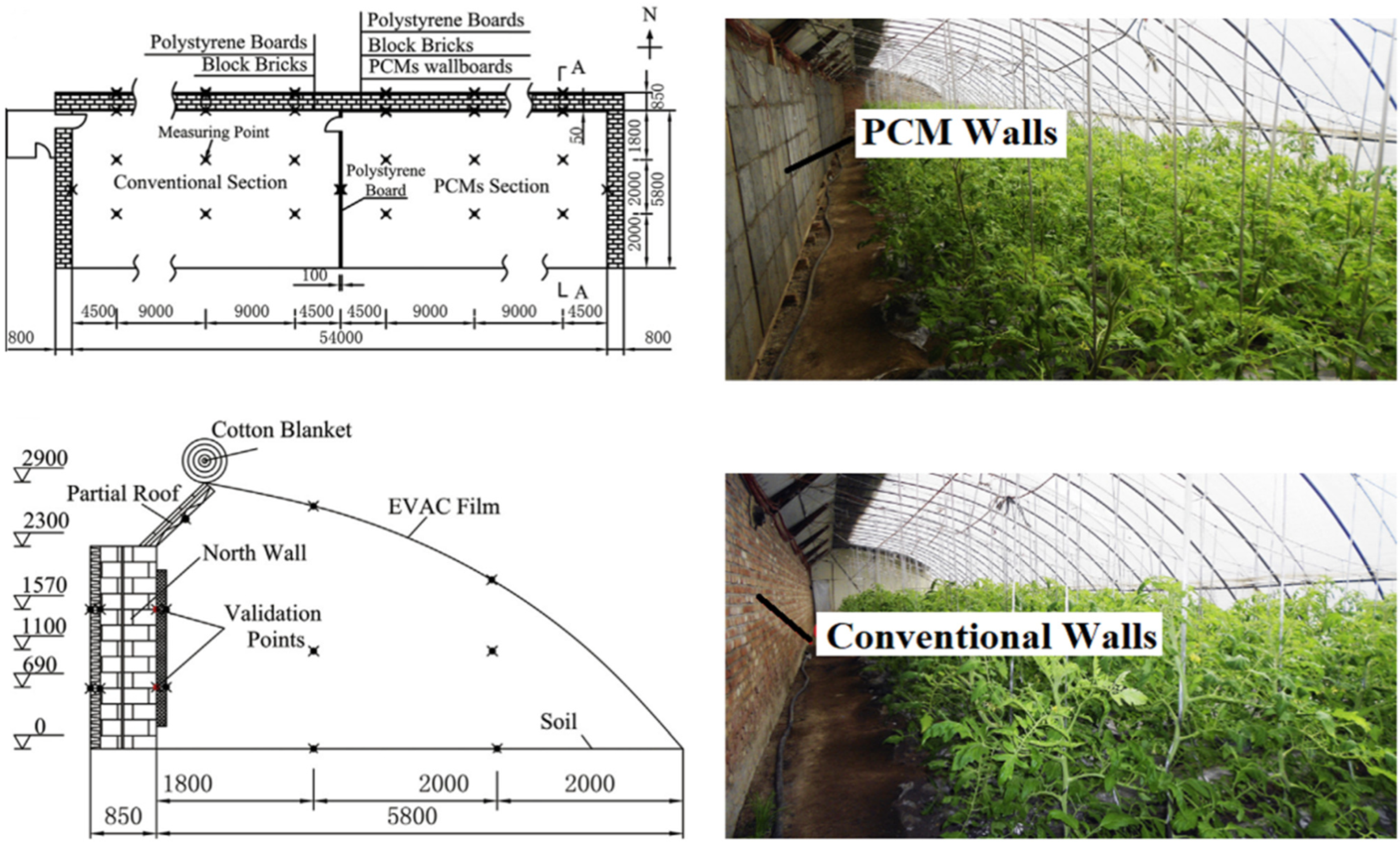
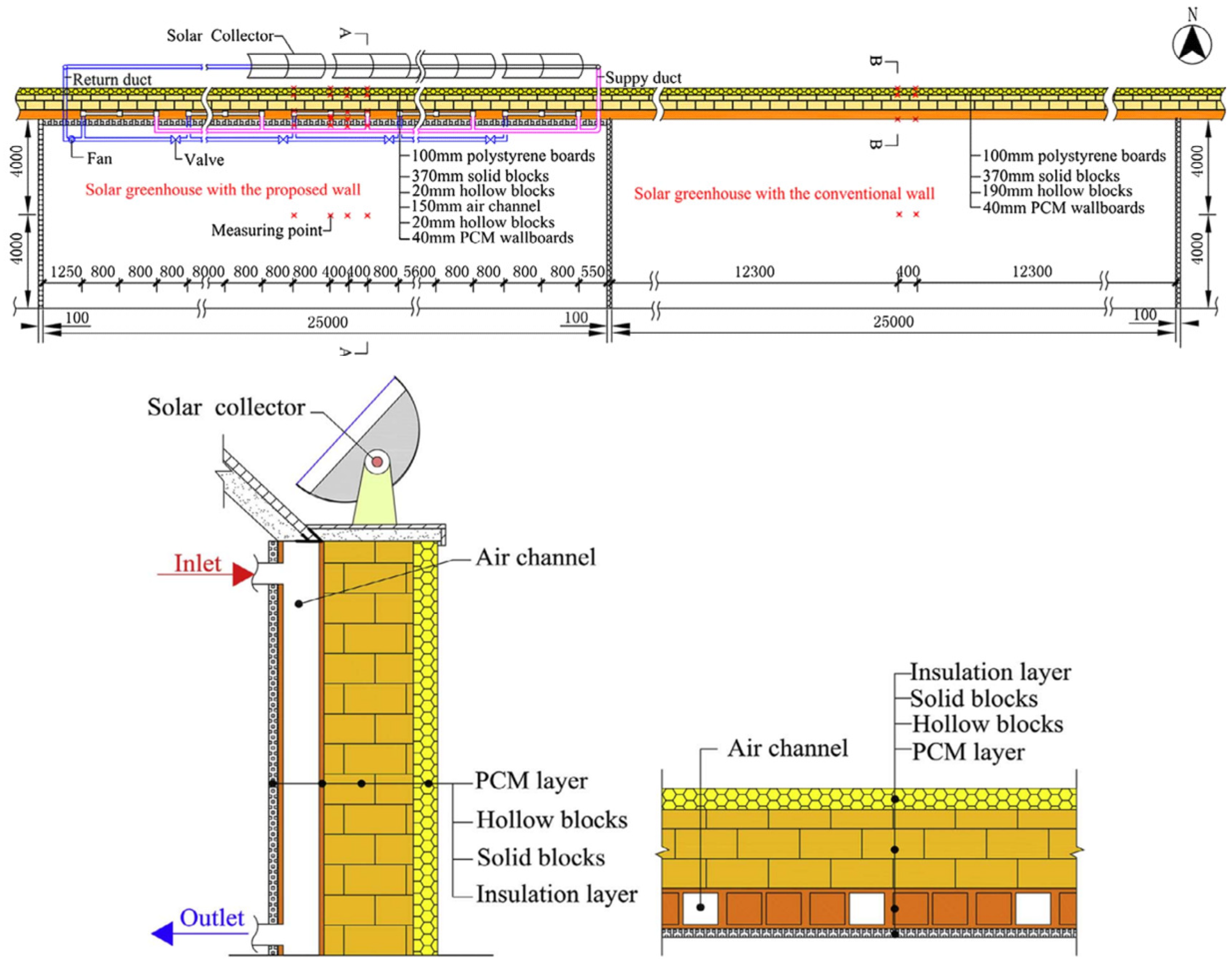
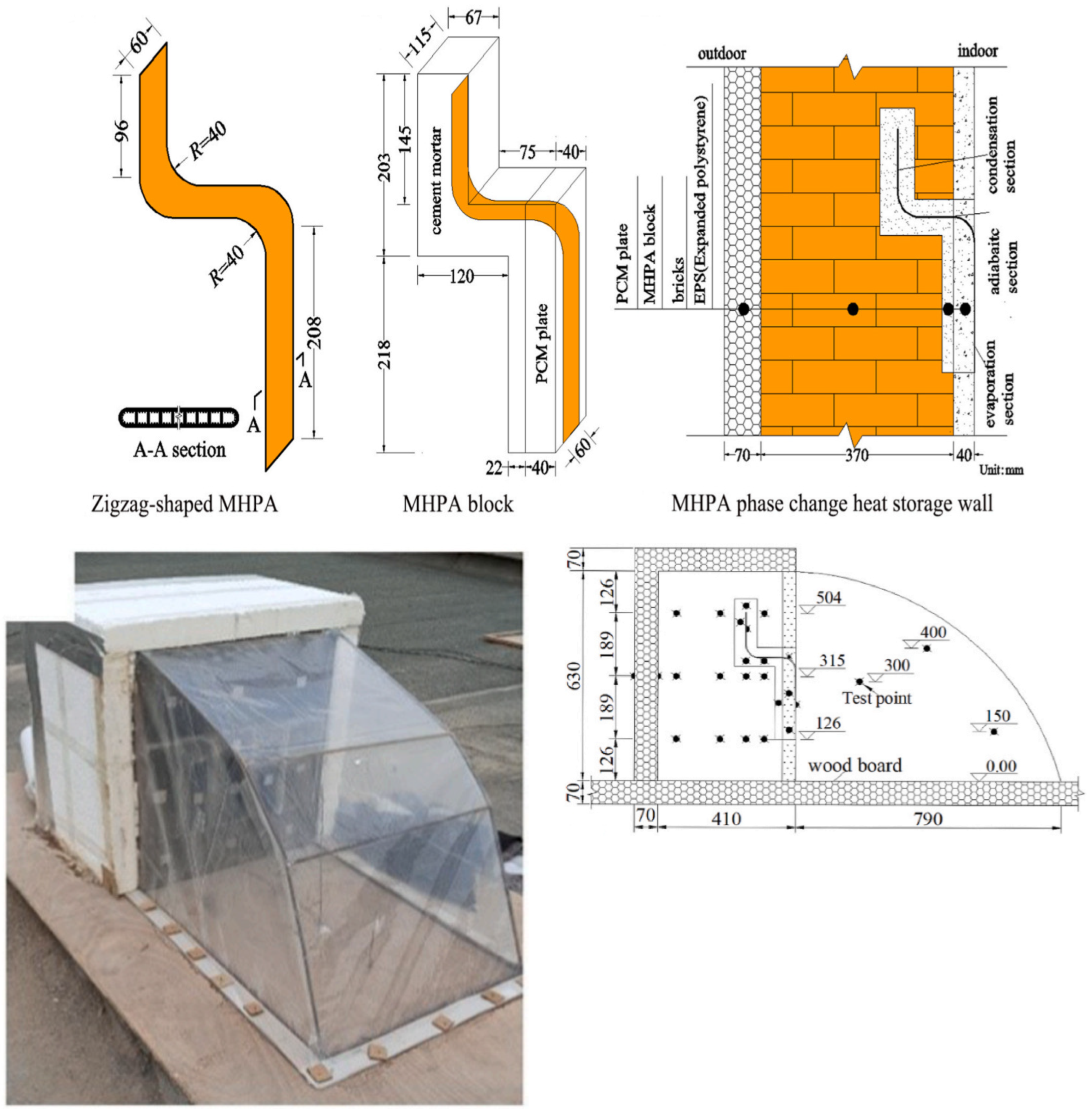
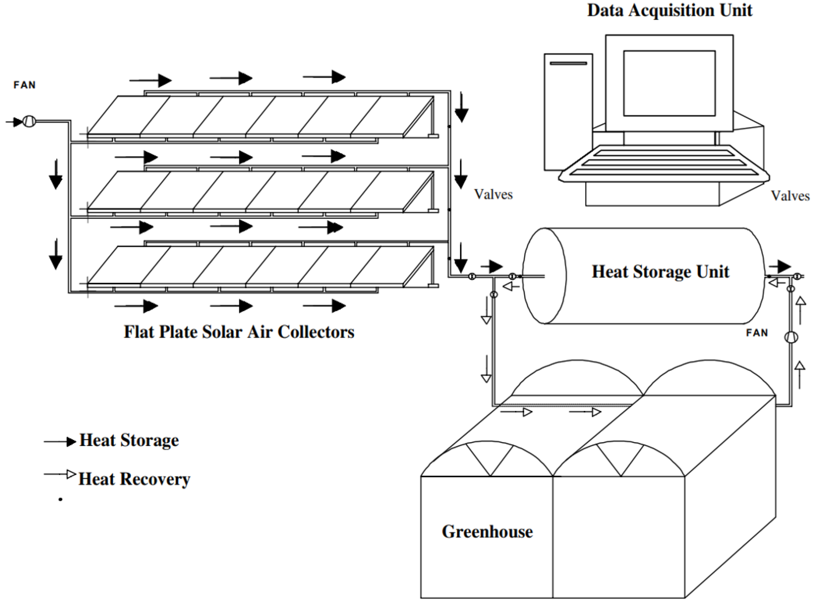
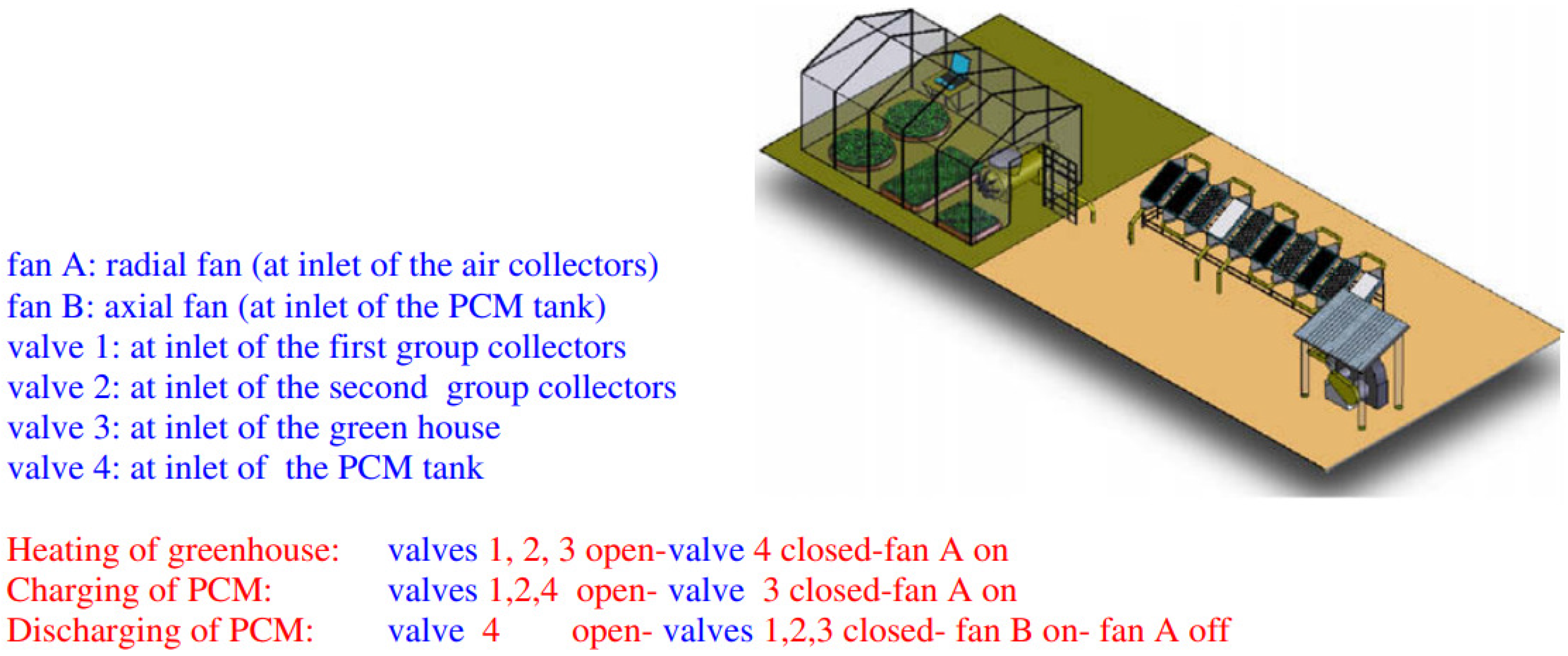
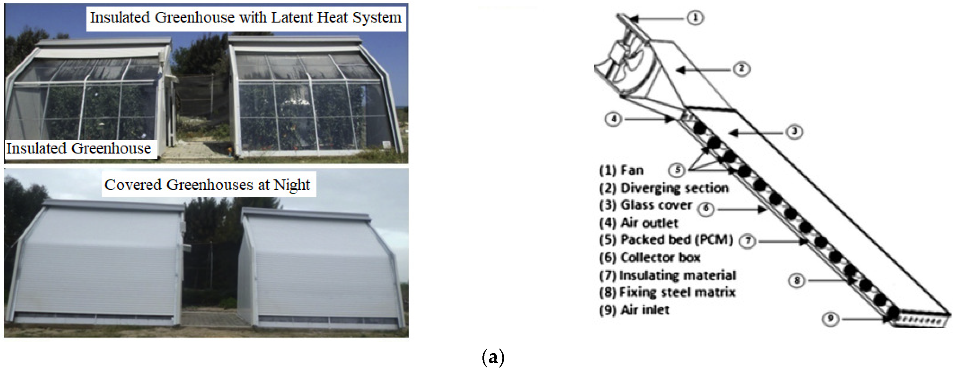

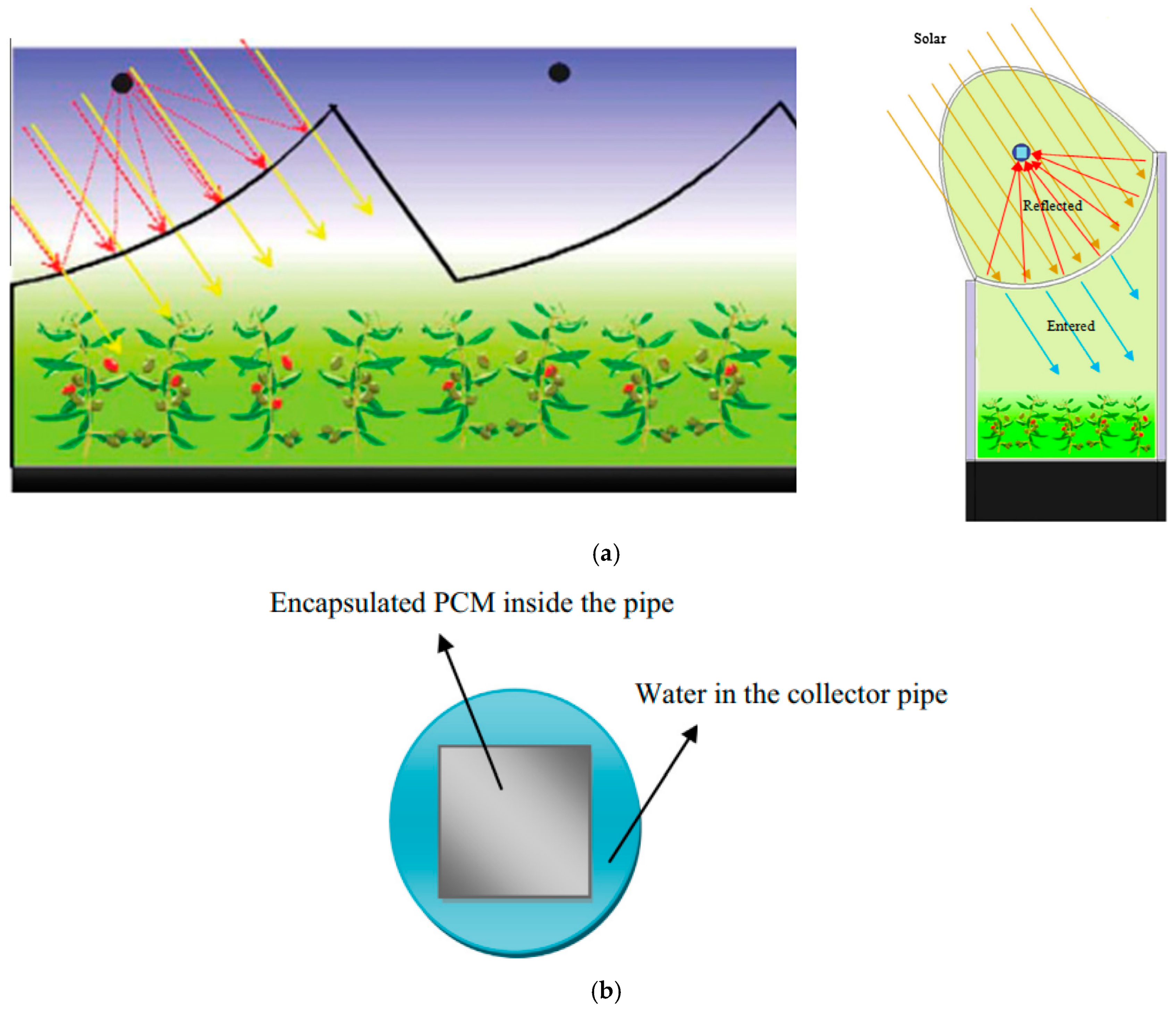


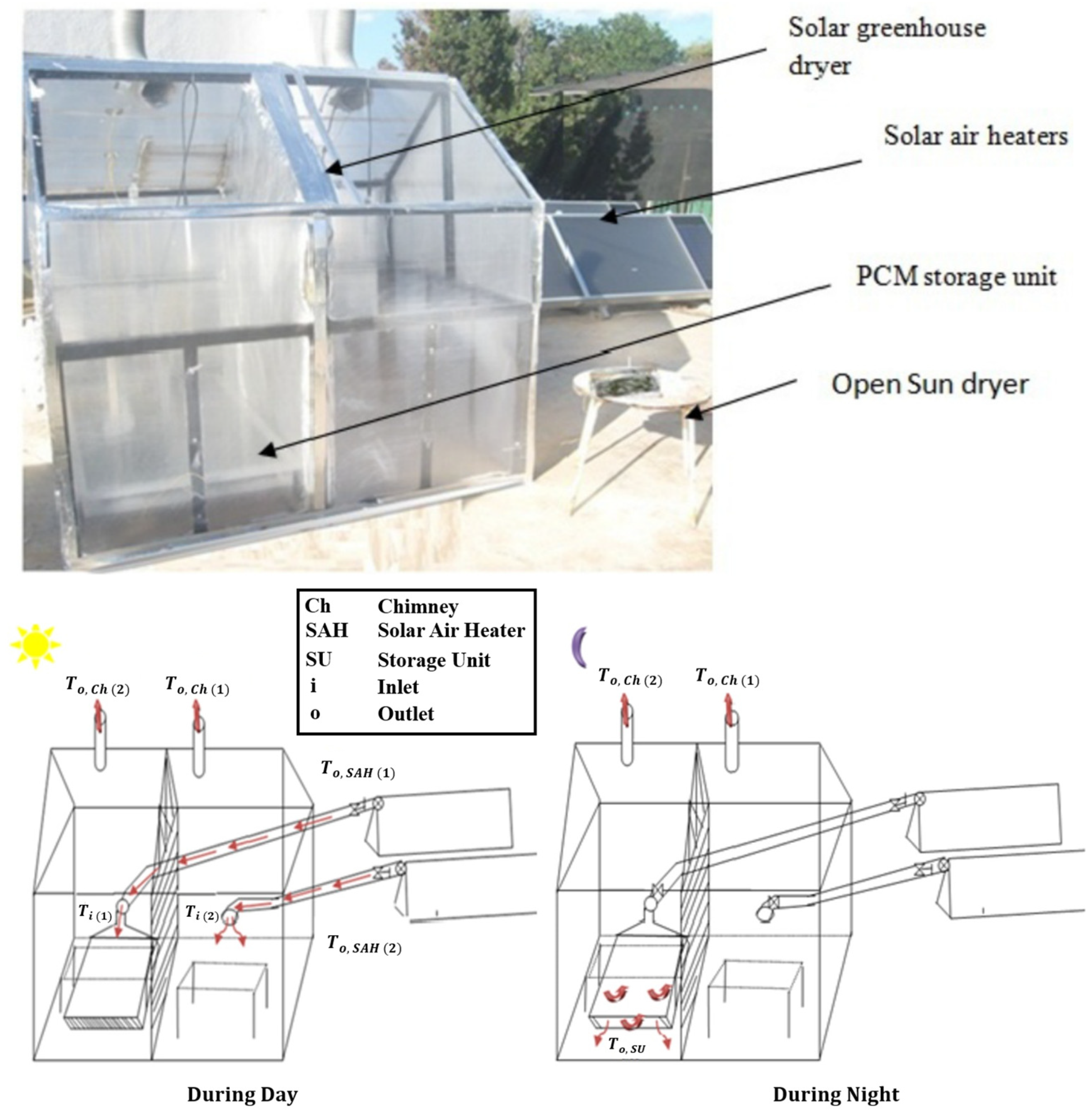
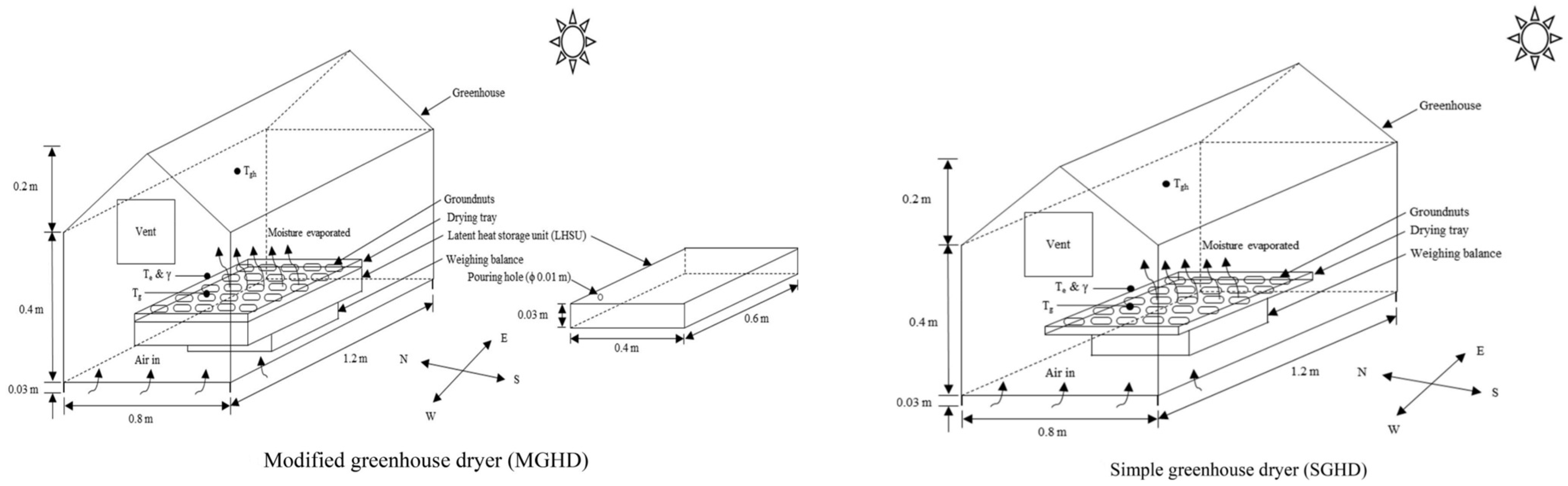
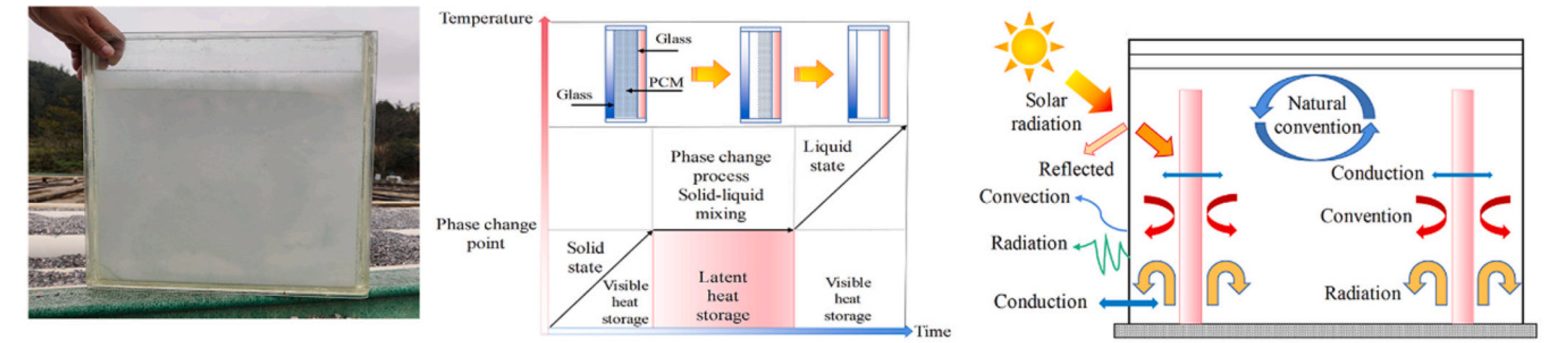

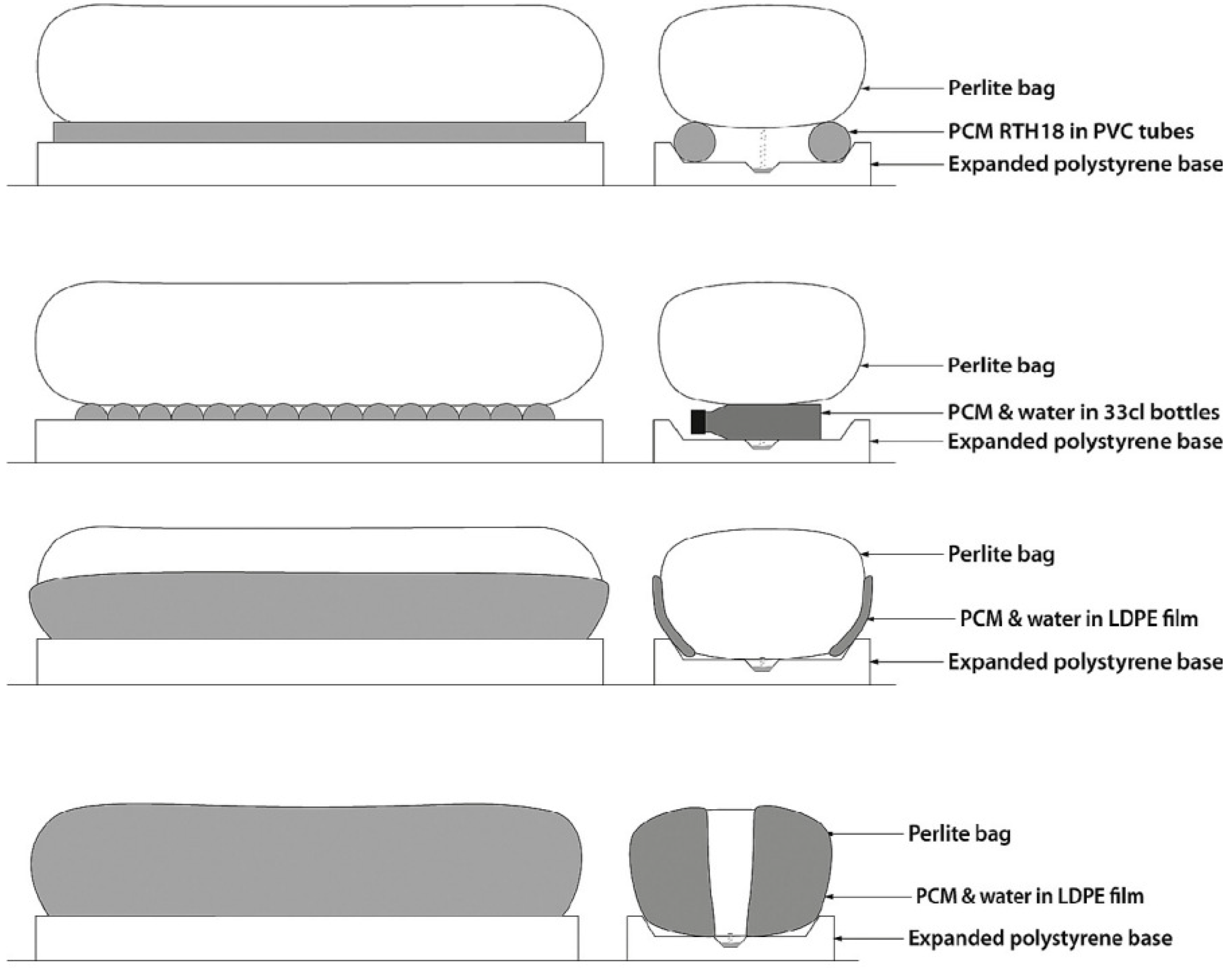
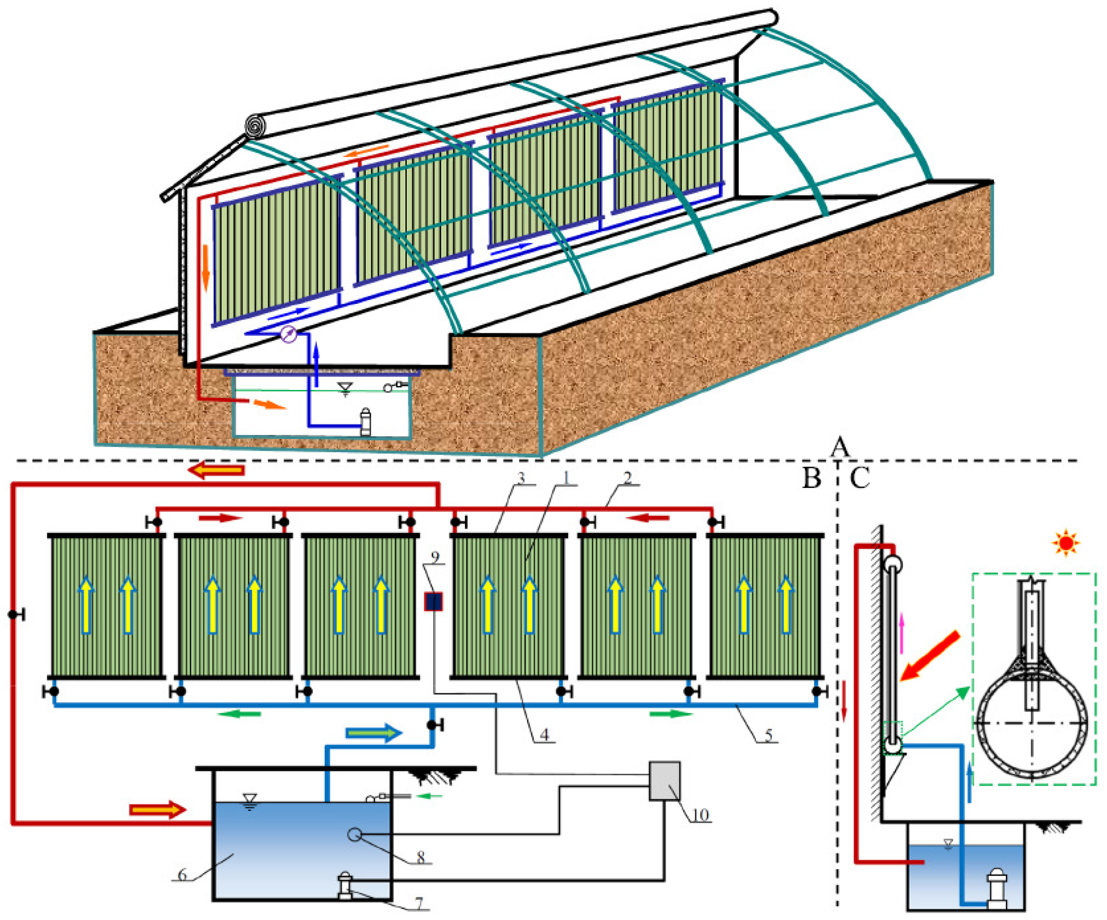
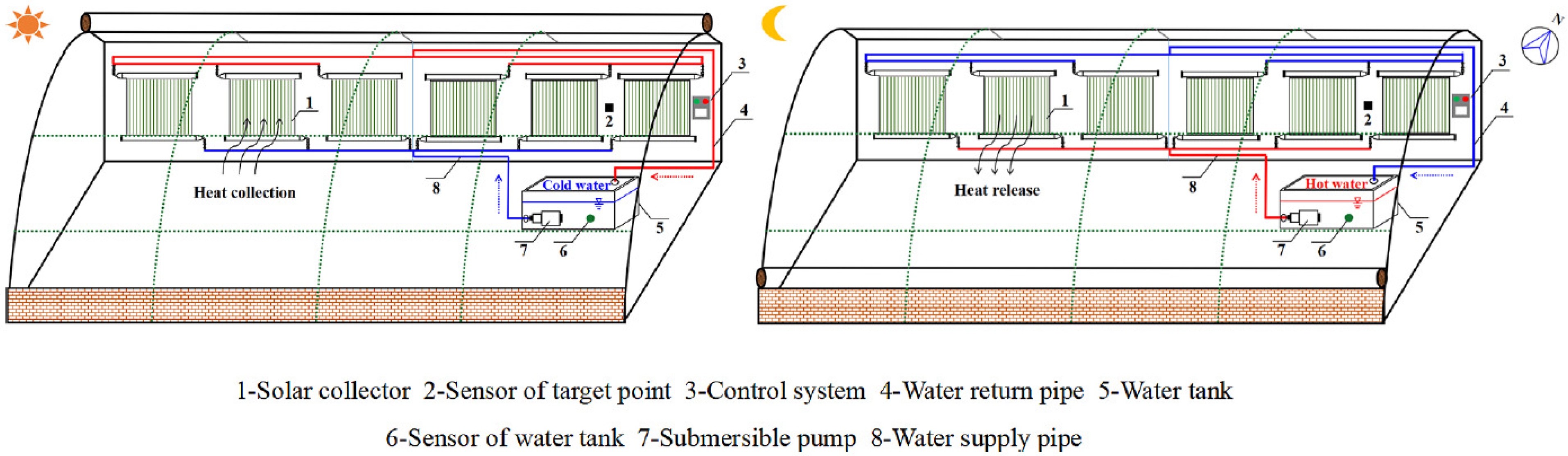
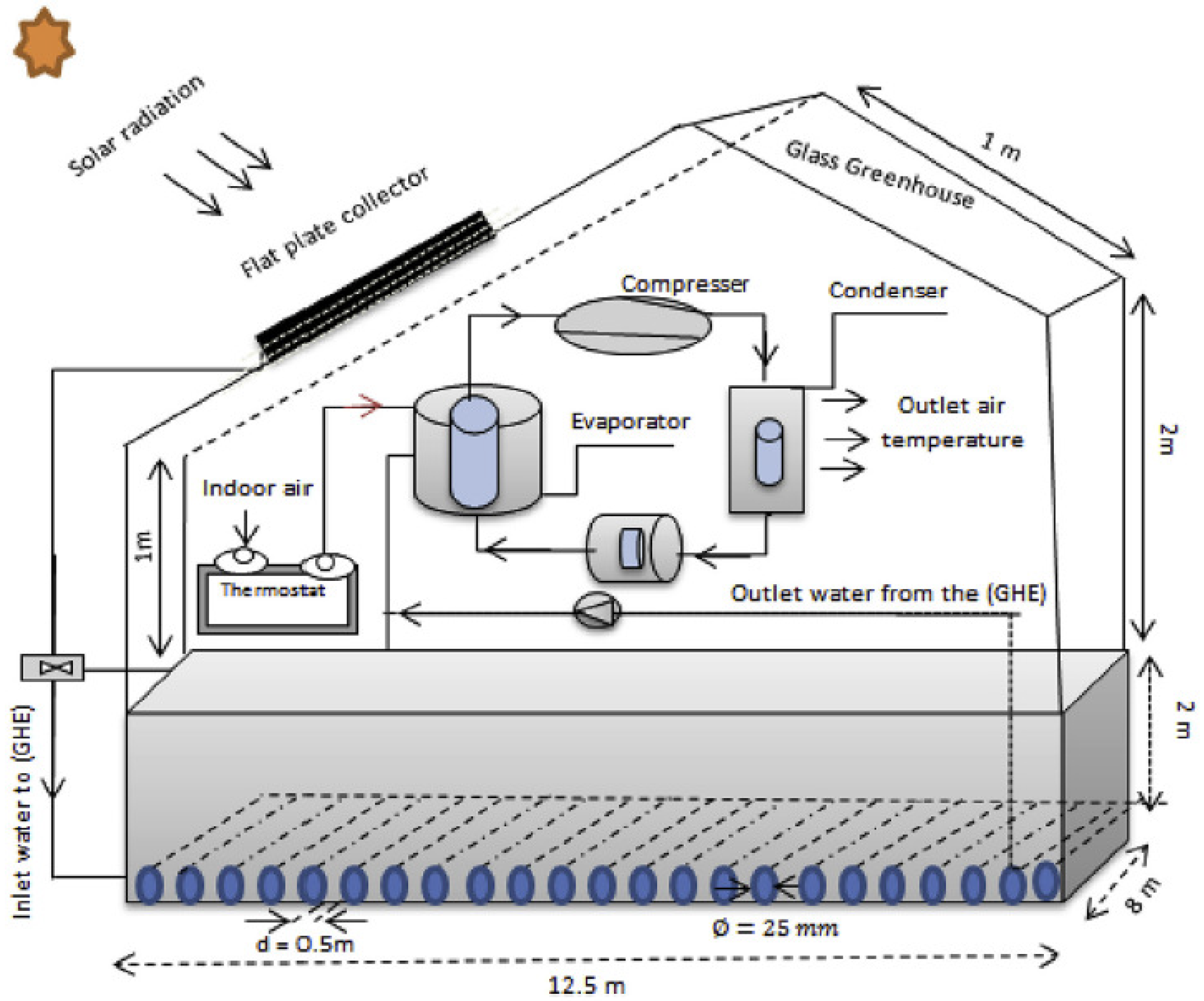
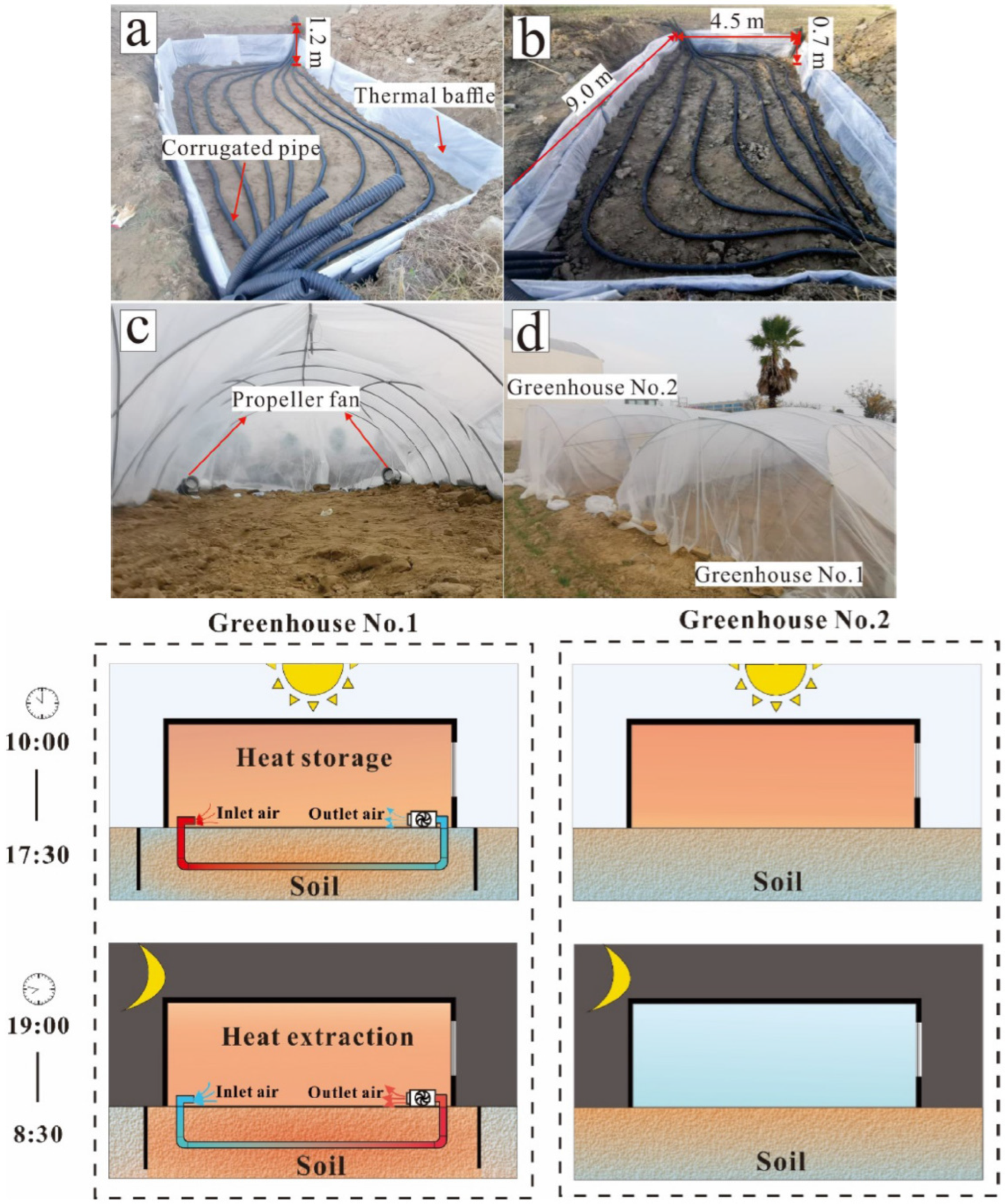
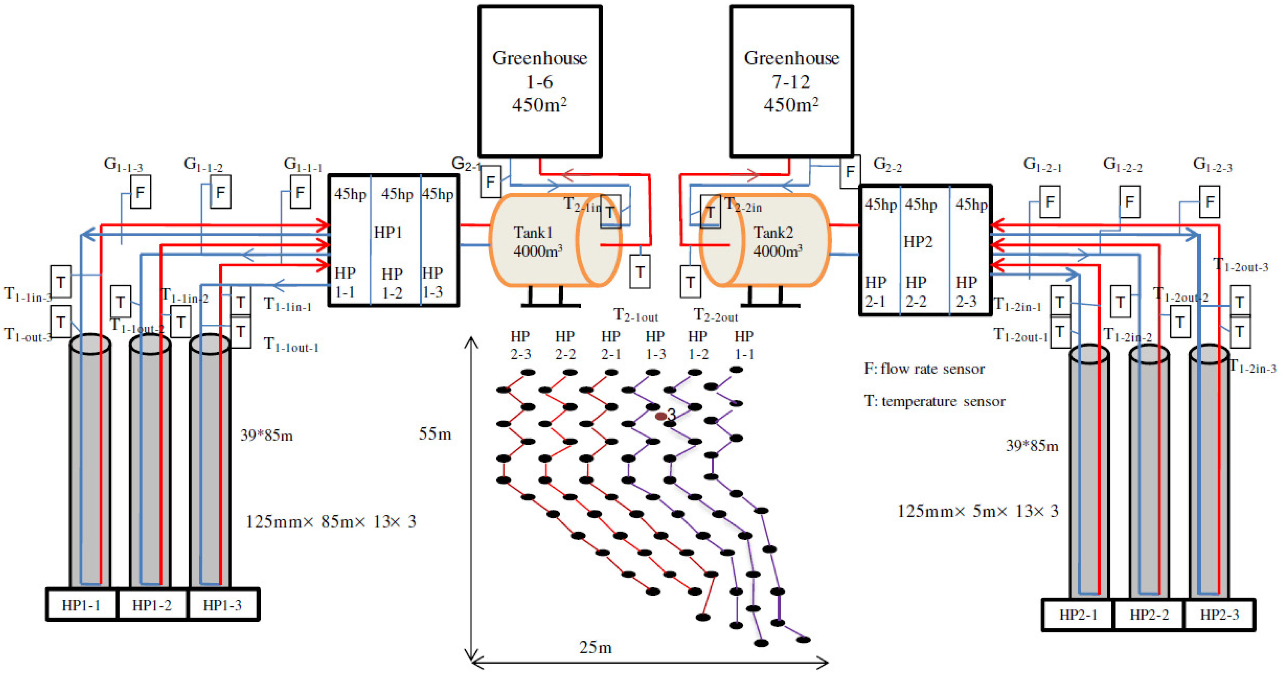
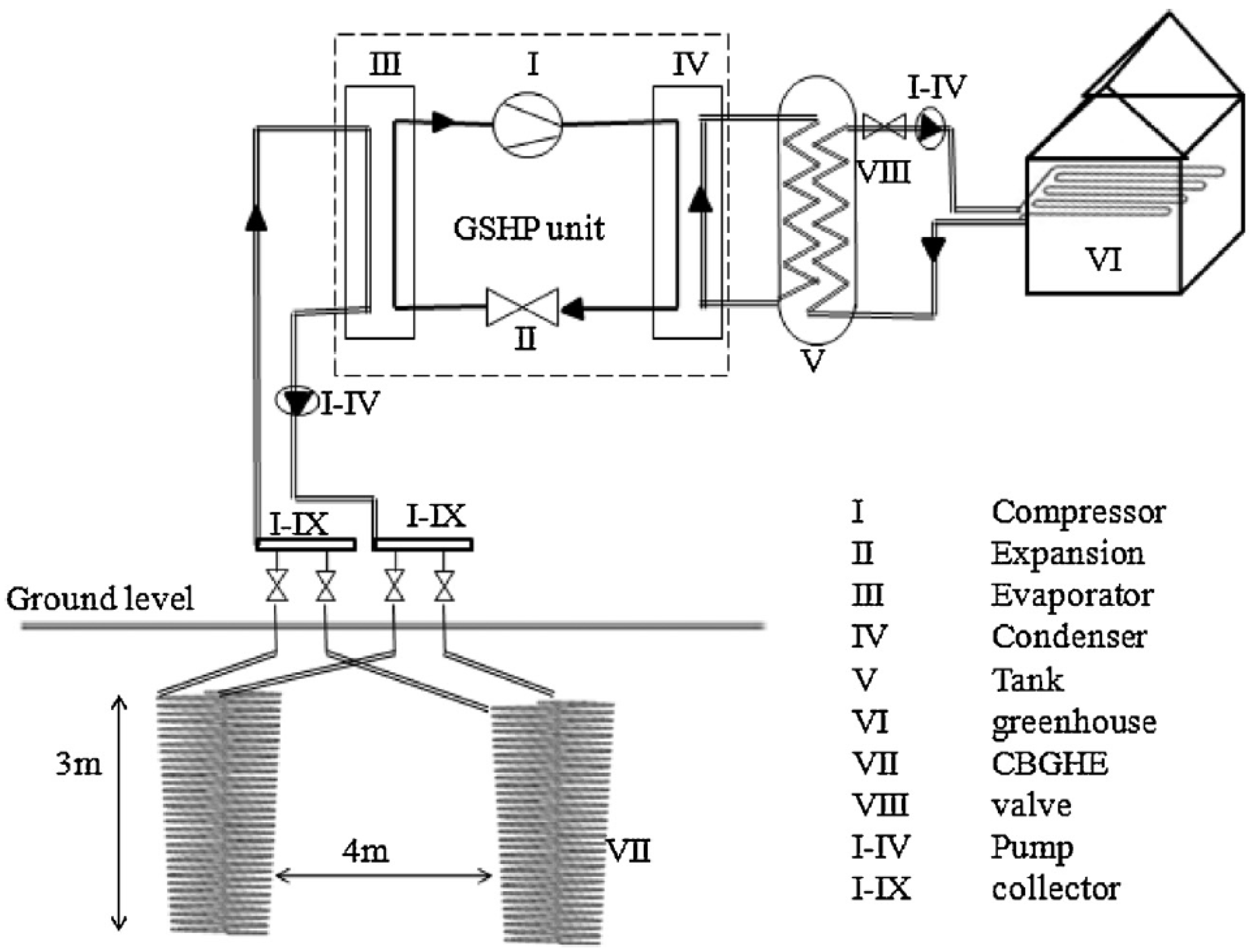
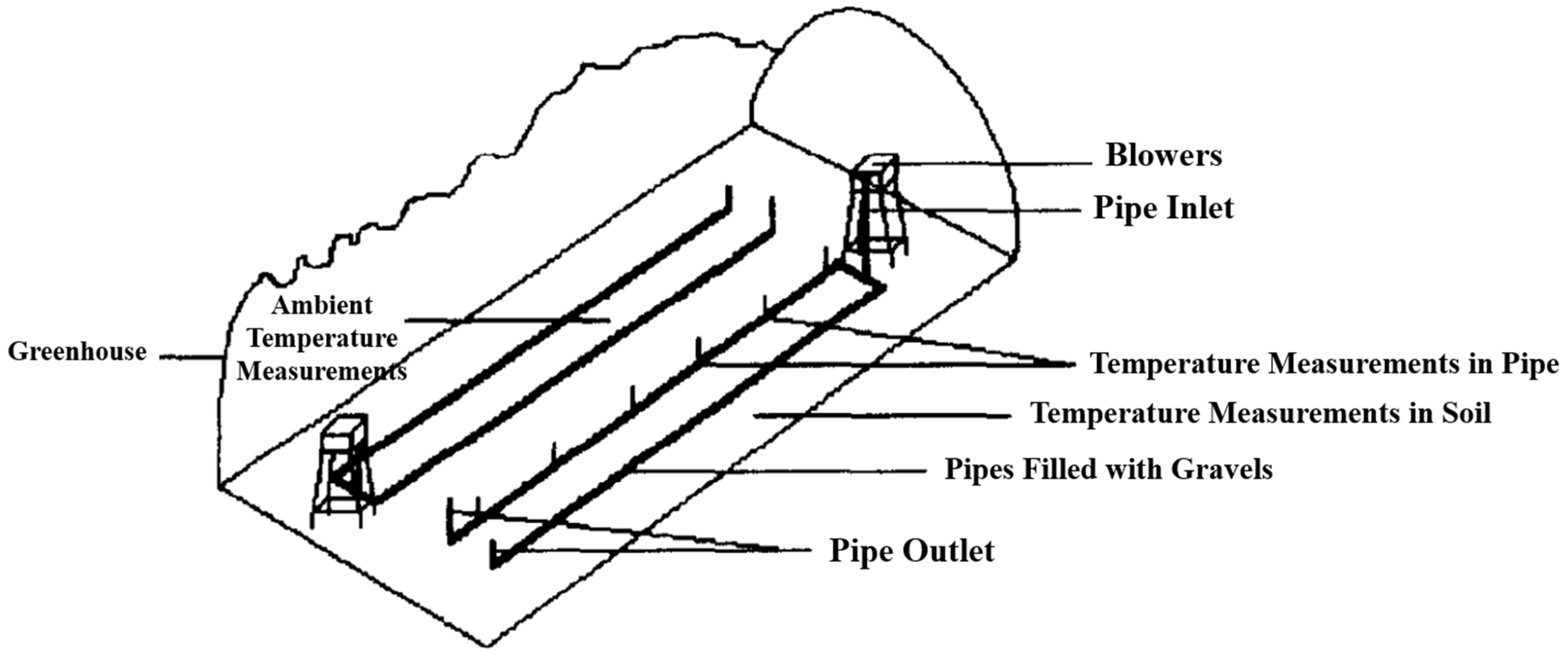
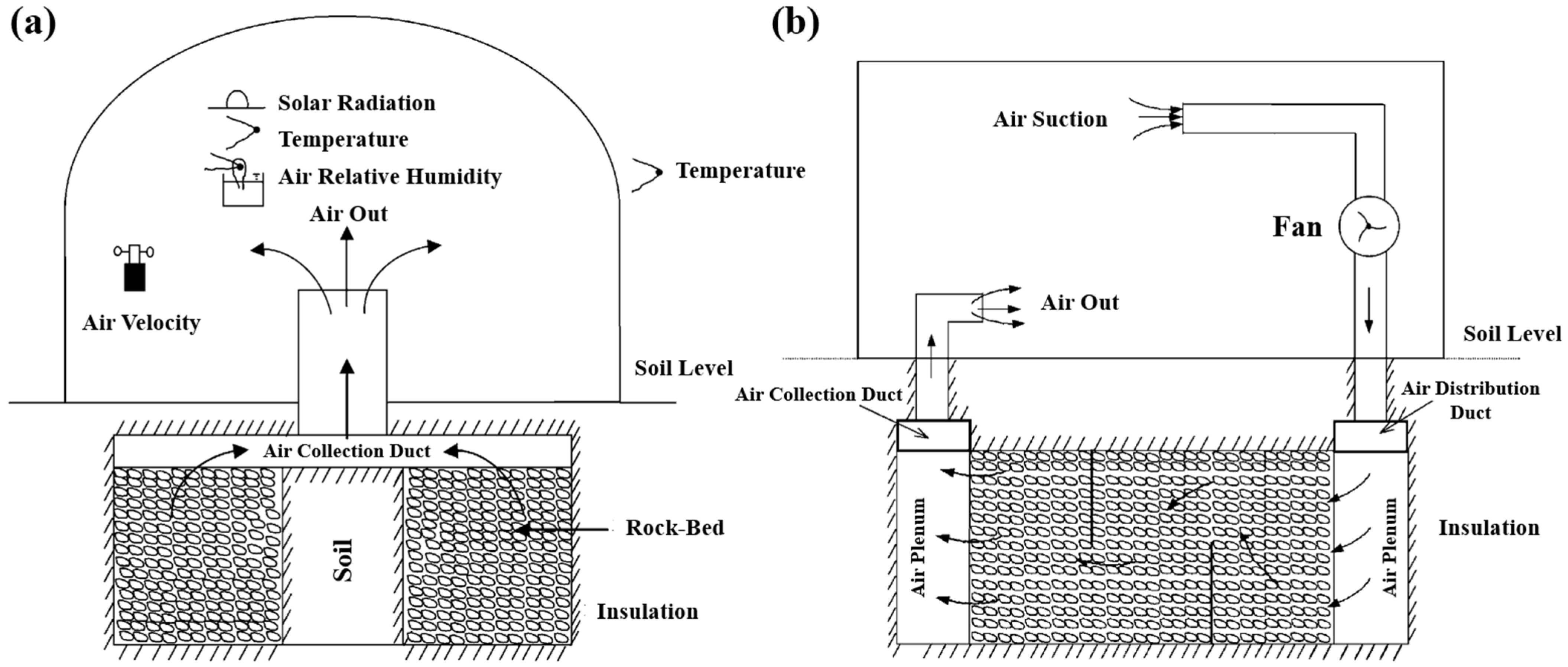
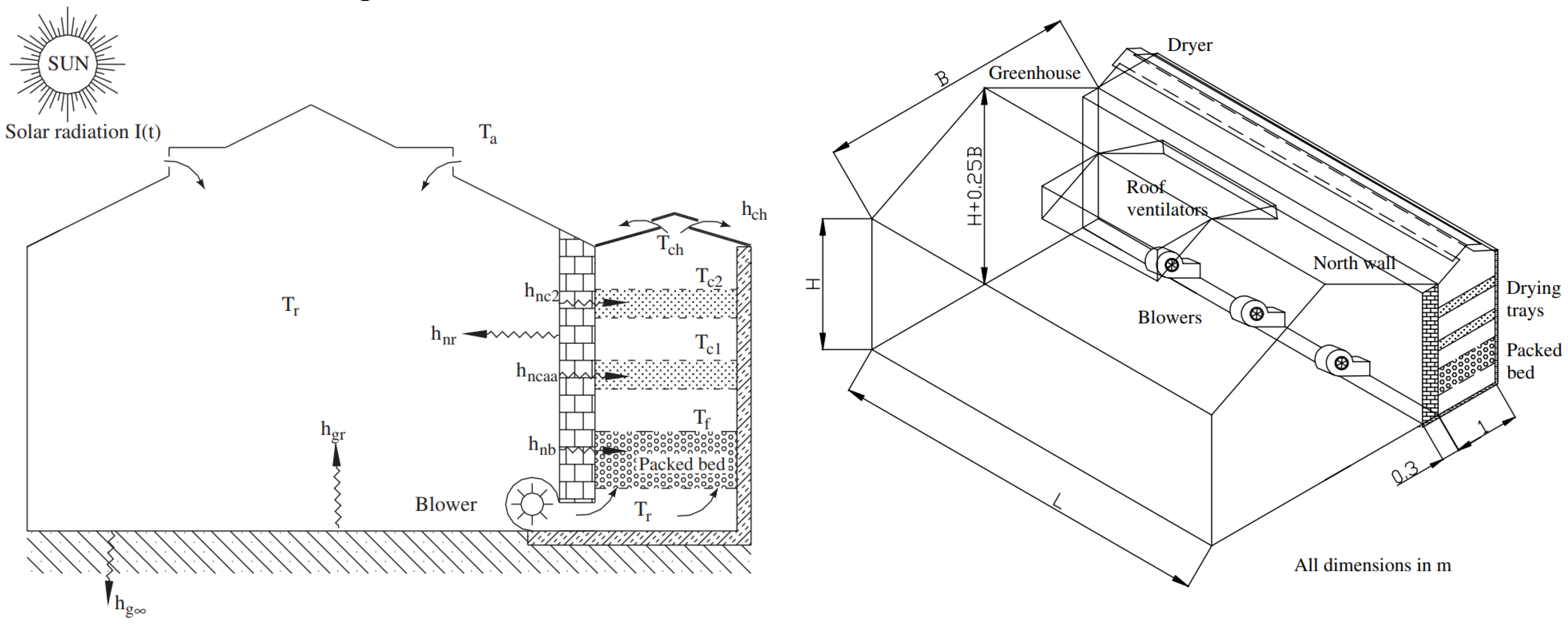
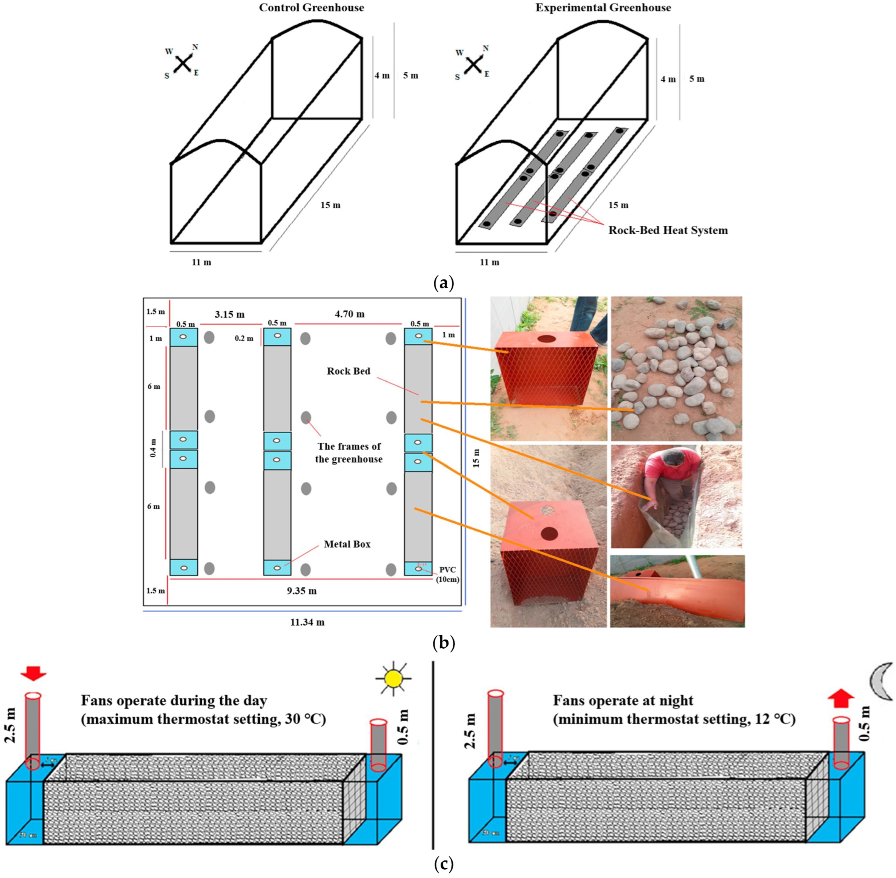

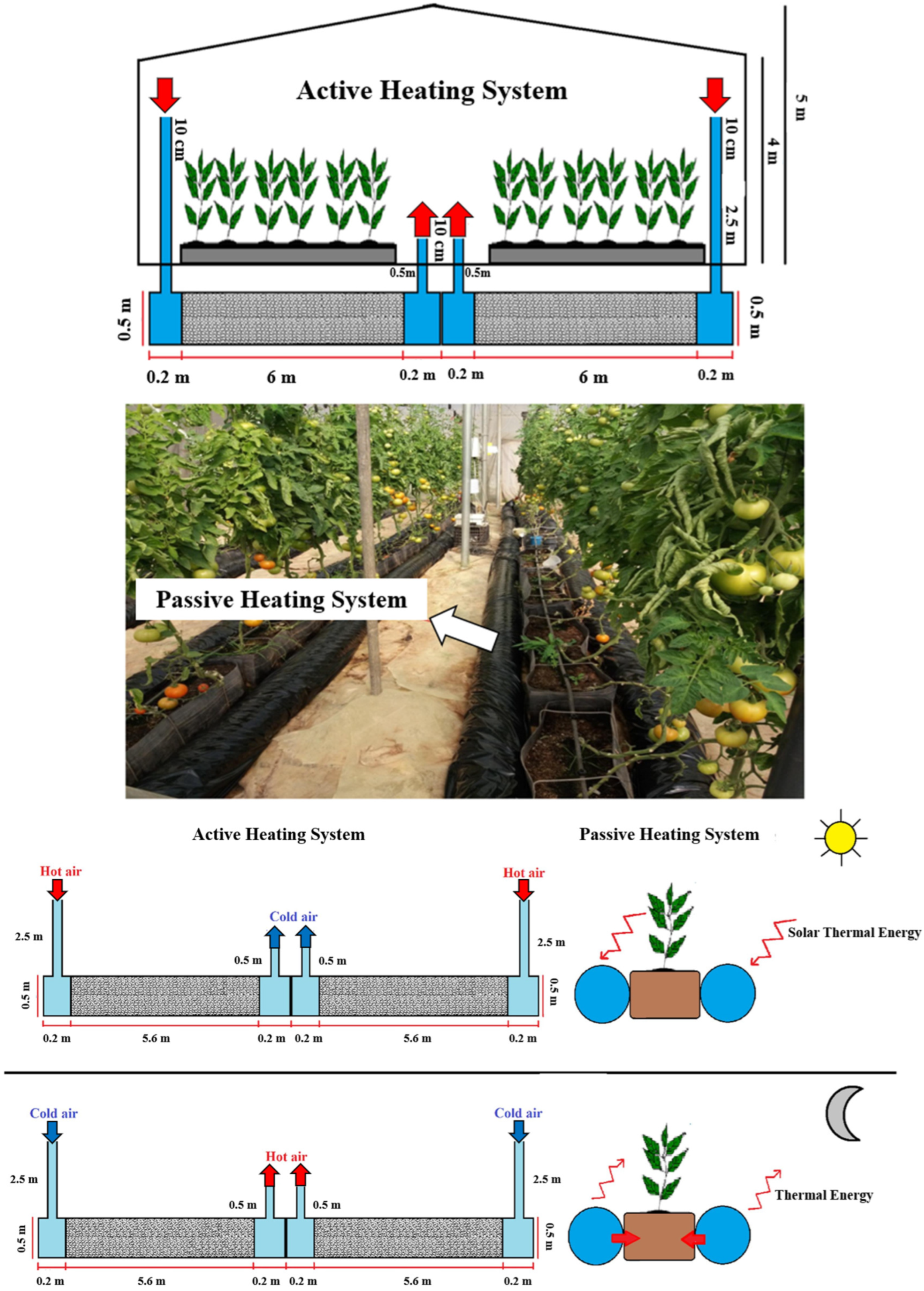

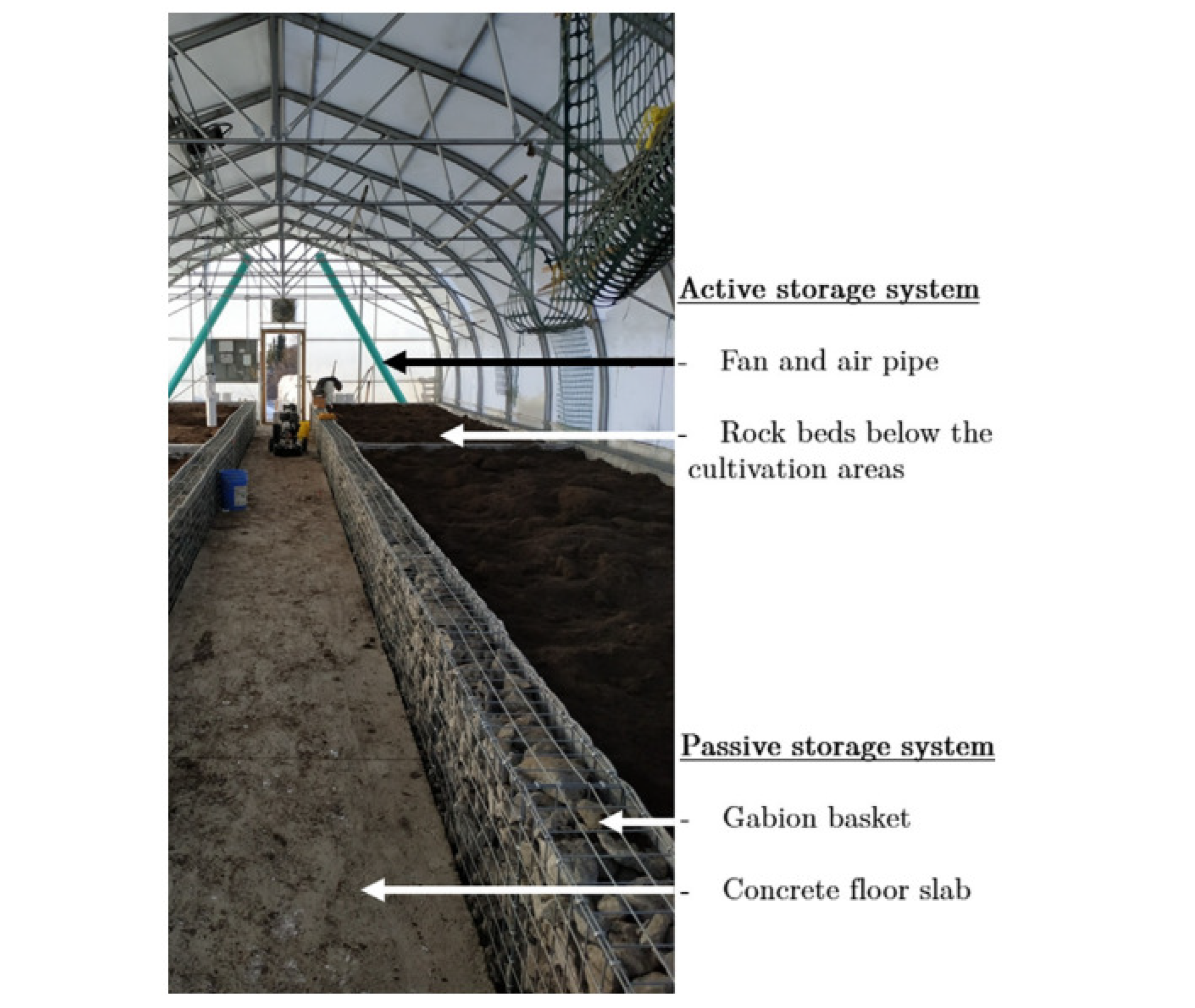

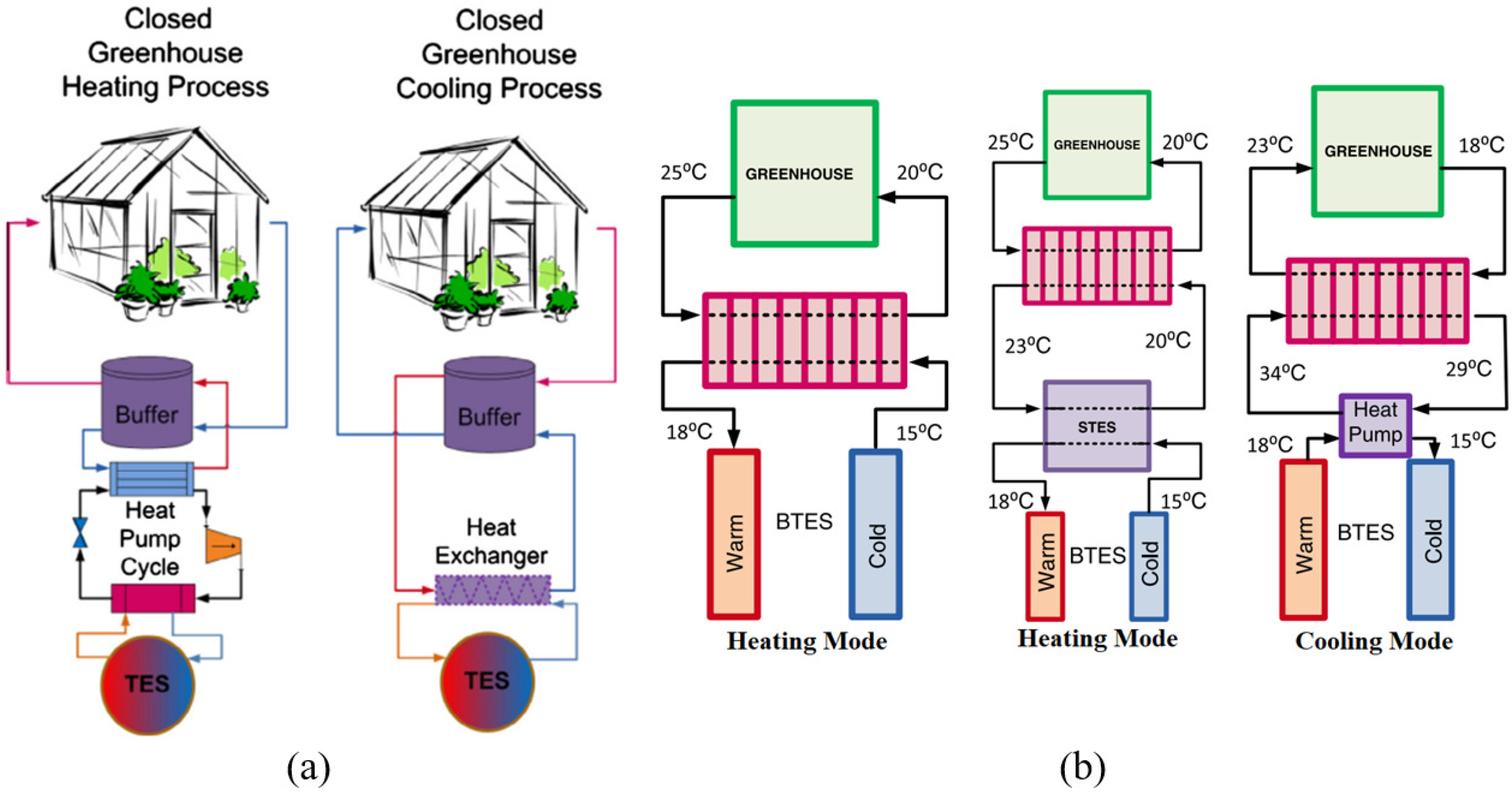
Disclaimer/Publisher’s Note: The statements, opinions and data contained in all publications are solely those of the individual author(s) and contributor(s) and not of MDPI and/or the editor(s). MDPI and/or the editor(s) disclaim responsibility for any injury to people or property resulting from any ideas, methods, instructions or products referred to in the content. |
© 2024 by the authors. Licensee MDPI, Basel, Switzerland. This article is an open access article distributed under the terms and conditions of the Creative Commons Attribution (CC BY) license (https://creativecommons.org/licenses/by/4.0/).