
Reduction of Torque Ripple and Axial Force in a Fully Pitched Axial Flux Switched Reluctance Motor Using a Double Stator Structure


Abstract
:1. Introduction
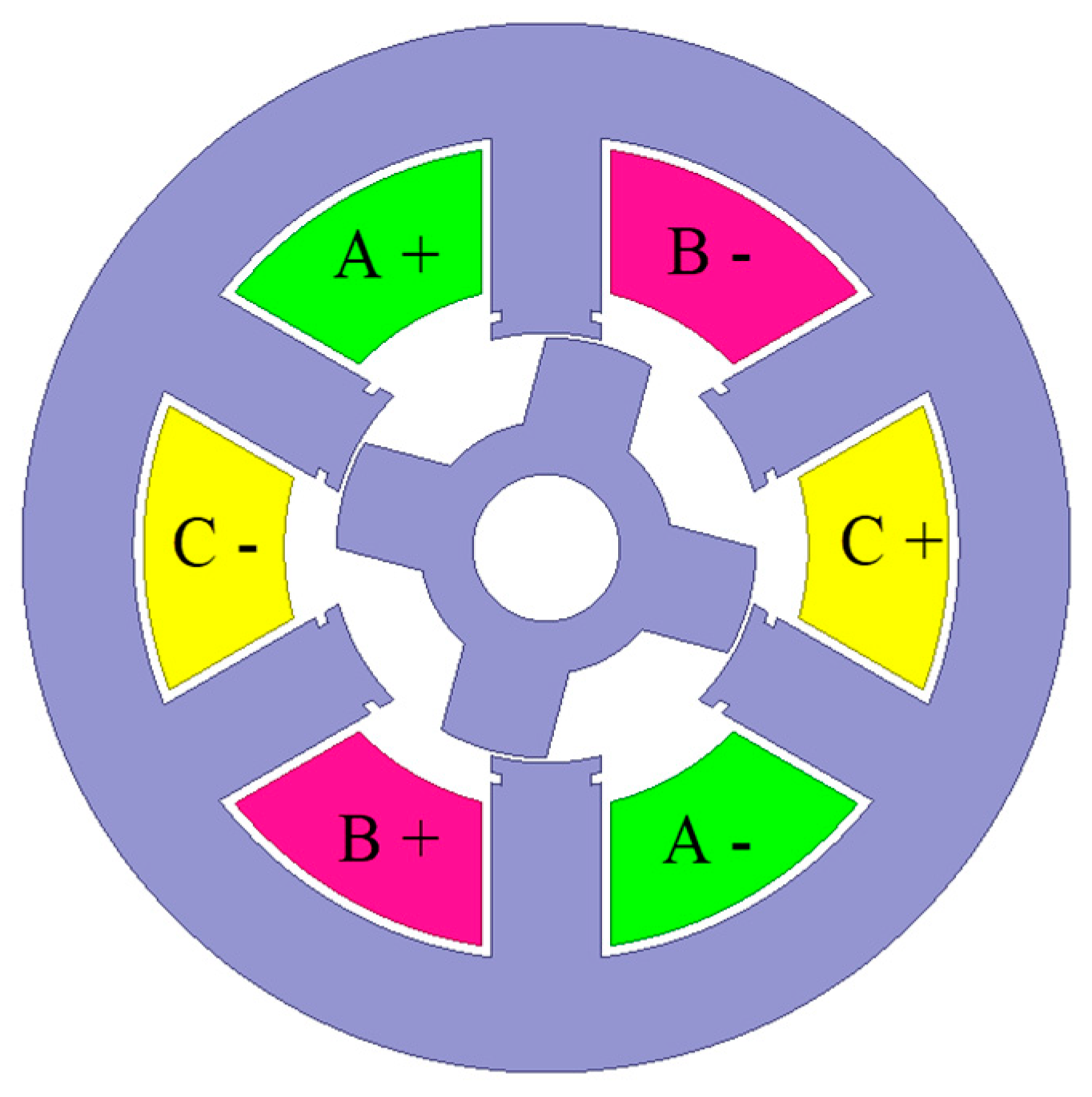
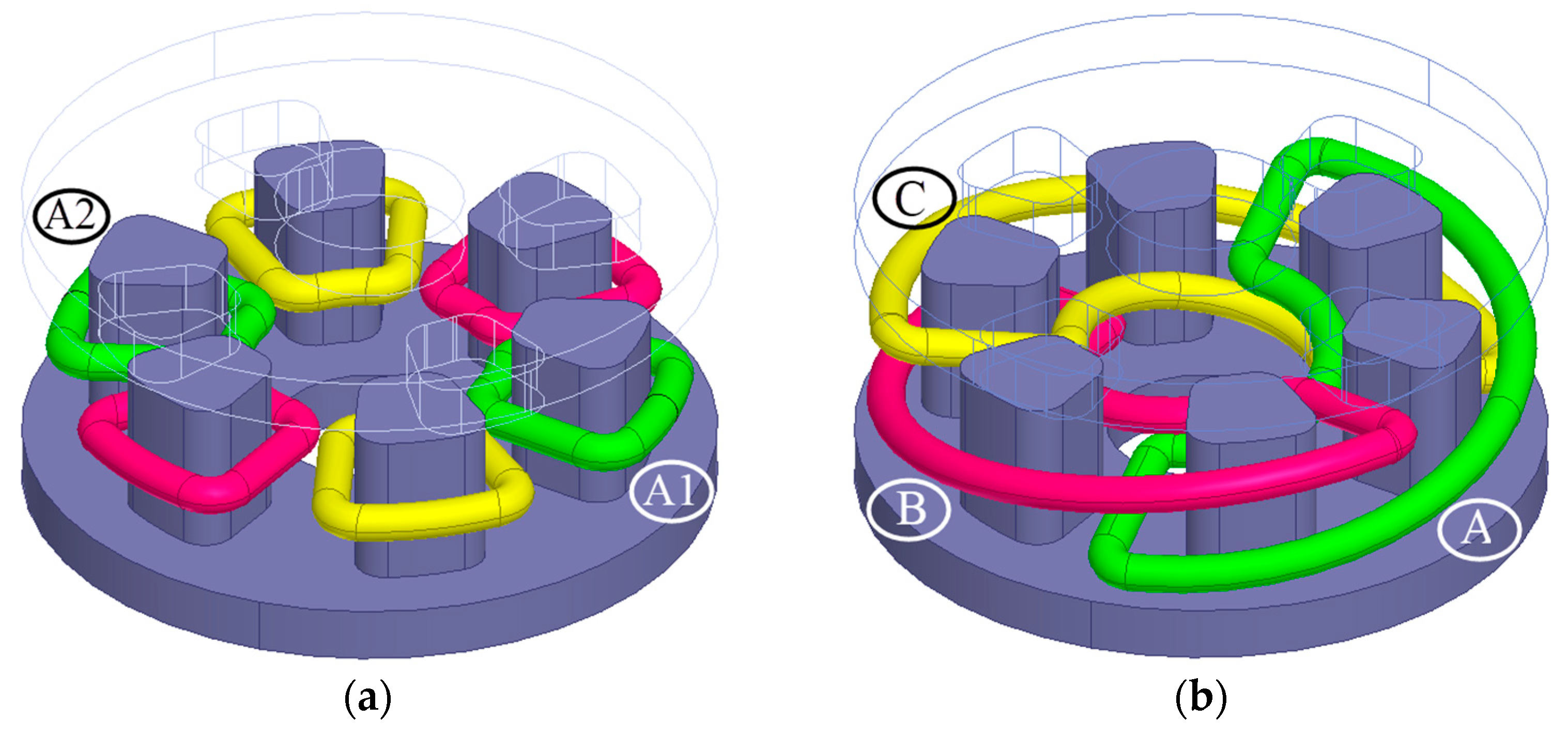
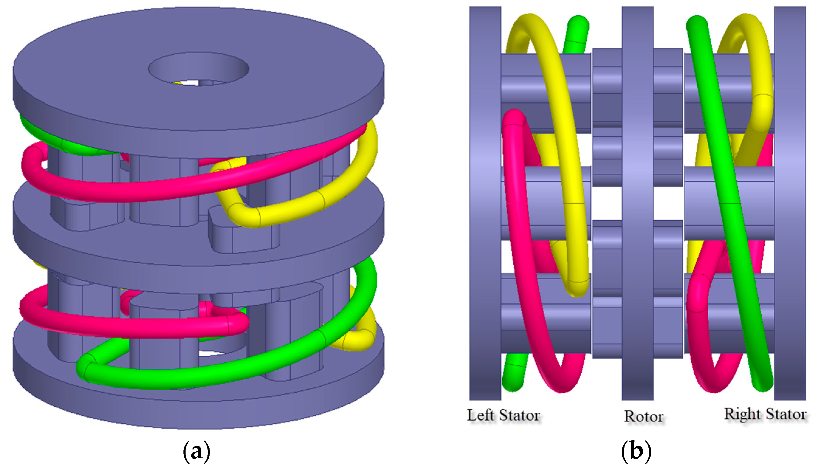
2. General Structure of Fully Pitched SRMs
Fully Pitched AFSRMs
3. General Discussion
4. Analysis of Proposed FP-AFSRM
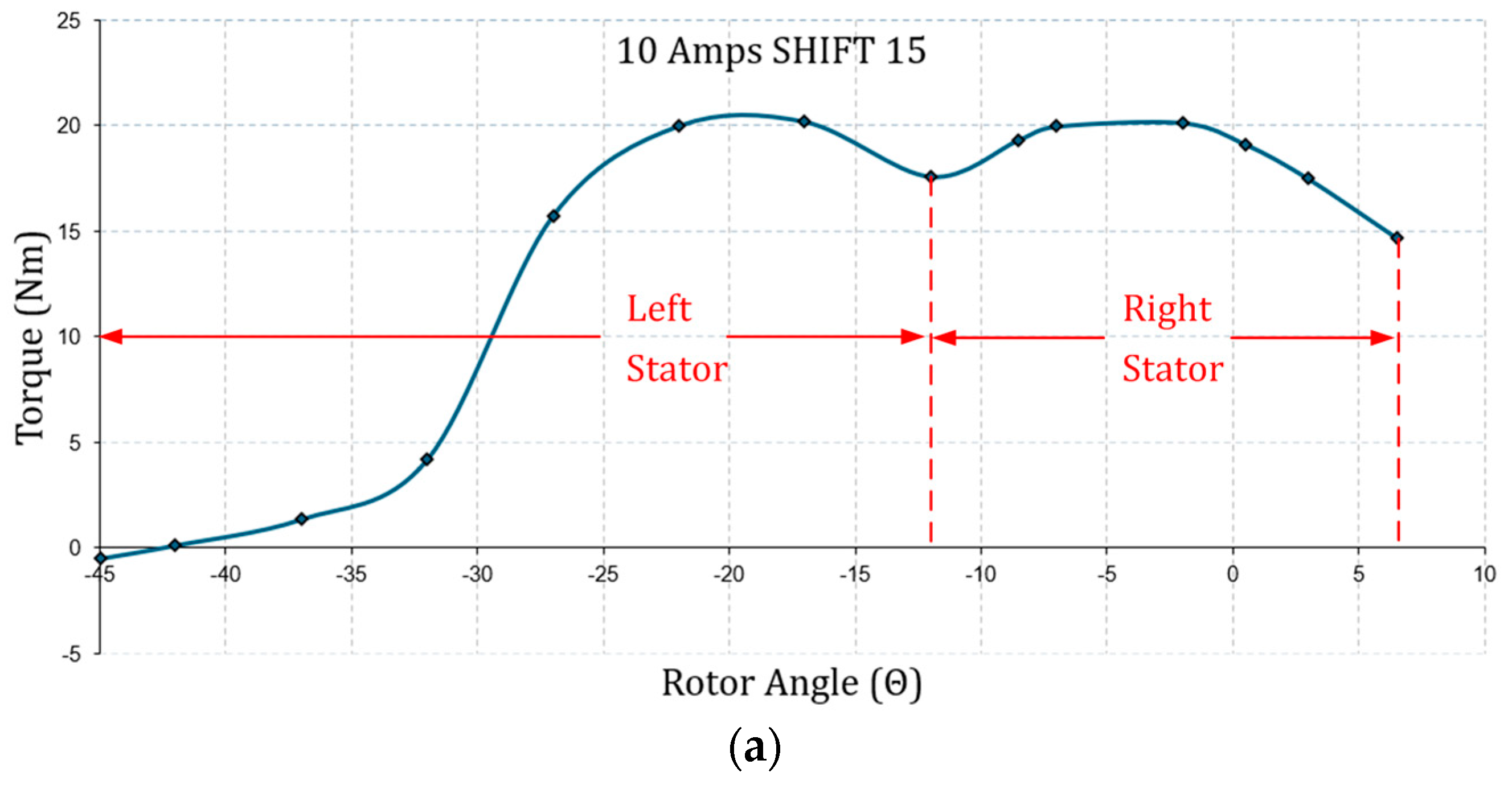
4.1. Finite Element Analysis
4.2. Comparison of Magnetostatic Analysis Results and Discussion
5. Conclusions
Funding
Institutional Review Board Statement
Informed Consent Statement
Data Availability Statement
Conflicts of Interest
References
- Gu, W.-K.; Yang, C.-W.; Liaw, C.-M. An EV SRM drive and its interconnected operations integrated into grid, microgrid, and vehicle. Appl. Sci. 2024, 14, 3032. [Google Scholar] [CrossRef]
- Sivasamy, S.; Sundaramoorthy, P.; Beno, M. A comprehensive investigation of outer rotor permanent magnet switched reluctance motor for enhanced performance in electric vehicles. IEEE Can. J. Electr. Comput. Eng. 2023, 46, 342–347. [Google Scholar] [CrossRef]
- Feng, L.; Sun, X.; Guo, D.; Yao, M.; Diao, K. Advanced torque sharing function strategy with sliding mode control for switched reluctance motors. IEEE Trans. Transp. Electrif. 2024, 10, 2302–2311. [Google Scholar] [CrossRef]
- Lorencki, J.; Radkowski, S. Mechanical faults analysis in switched reluctance motor. Appl. Sci. 2024, 14, 3452. [Google Scholar] [CrossRef]
- Abdalmagid, M.; Bakr, M.H.; Emadi, A. A New technique for radial and tangential force calculation time reduction for the optimization process of SRMs. IEEE Access 2023, 11, 66076–66093. [Google Scholar] [CrossRef]
- Sahu, A.K.; Emadi, A.; Bilgin, B. Noise and vibration in switched reluctance motors: A review on structural materials, vibration dampers, acoustic impedance, and noise masking methods. IEEE Access 2023, 11, 27702–27718. [Google Scholar] [CrossRef]
- Hamouda, M.; Al-Amyal, F.; Elsherbiny, H.; Odinaev, I.; Menaem, A.A.; Alluhaybi, K.; Zaky, A.A. A Novel interturn fault tolerant based average torque control of switched reluctance motors for electric vehicles. IEEE Access 2024, in press. [CrossRef]
- Belhadi, M.; Krebs, G.; Marchand, C.; Hannoun, H.; Mininger, X. Evaluation of axial srm for electric vehicle application. Electr. Power Syst. Res. 2017, 148, 155–161. [Google Scholar] [CrossRef]
- Andrada, P.; Martínez, E.; Torrent, M.; Blanqué, B. Electromagnetic evaluation of an in-wheel double rotor axial-flux switched reluctance motor for electric traction. In Proceedings of the International Conference on Renewable Energies and Power Quality (ICREPQ’17), Malaga, Spain, 4–6 April 2017. [Google Scholar]
- Padmanaban, L.A.; Saravanan, P. Design, analysis and comparison of switched reluctance motors for electric vehicle application. Automatika 2023, 64, 239–247. [Google Scholar] [CrossRef]
- Cheng, H.; Chen, H.; Yang, Z. Design indicators and structure optimisation of switched reluctance machine for electric vehicles. IET Electr. Power Appl. 2015, 9, 319–331. [Google Scholar] [CrossRef]
- Zhu, J.; Cheng, K.W.E.; Xue, X.; Zou, Y. Design of a new enhanced torque in-wheel switched reluctance motor with divided teeth for electric vehicles. IEEE Trans. Magn. 2017, 53, 2501504. [Google Scholar] [CrossRef]
- Bostanci, E.; Moallem, M.; Parsapour, A.; Fahimi, B. Opportunities and challenges of switched reluctance motor drives for electric propulsion: A Comparative study. IEEE Trans. Transp. Electrif. 2017, 3, 58–75. [Google Scholar] [CrossRef]
- Gundogmus, O.; Das, S.; Sozer, Y.; Kutz, J.; Tylenda, J.; Wright, R.L. NVH Performance improvement in switched reluctance machines by simultaneous radial force and torque ripple minimizations. IEEE Trans. Trans. Transp. Electrif. 2024, in press. [CrossRef]
- Xiang, J.; Cai, Y.; El-Faouri, F.S.; Chiba, A. Radial force control in switched reluctance motors using strain gauges. In Proceedings of the IEEE Energy Conversion Congress and Exposition (ECCE), Nashville, TN, USA, 29 October–2 November 2023. [Google Scholar]
- Ma, j.; Li, j.; Fang, H.; Li, Z.; Liang, Z.; Fu, Z.; Xiao, L.; Qu, R. Optimal design of an axial-flux switched reluctance motor with grain-oriented electrical steel. IEEE Trans. Ind. Appl. 2017, 53, 5327–5337. [Google Scholar] [CrossRef]
- Goto, H. Double stator axial-flux switched reluctance motor for electric city commuters. In Proceedings of the International Power Electronics Conference (IPEC-Niigata 2018-ECCE Asia), Niigata, Japan, 20–24 May 2018. [Google Scholar]
- Son, D.; Lee, D.-H.; Ahn, J.-W. Design and analysis of double stator axial field type srm. In Proceedings of the IEEE Transportation Electrification Conference and Expo, Asia-Pacific (ITEC Asia-Pacific), Harbin, China, 7–10 August 2017. [Google Scholar]
- Wang, B.; Lee, D.-H.; Lee, C.-W.; Ahn, J.-W. Characteristics analysis of a novel segmental rotor axial field switched reluctance motor with single teeth winding. J. Power Electron. 2014, 14, 852–858. Available online: https://jpels.org/digital-library/manuscript/file/18091/S5_JPE-14-04-152.pdf (accessed on 1 September 2024). [CrossRef]
- Gillies, J. An Axial-Flux Switched Reluctance Motor for Light Electric Vehicles. Master’s Thesis, McMaster University, Hamilton, ON, Canada, 2020. [Google Scholar]
- Kermanipour, M.J.; Ganji, B. Modification in geometric structure of double-sided axial flux switched reluctance motor for mitigating torque ripple. IEEE Can. J. Electr. Comput. Eng. 2015, 38, 318–322. [Google Scholar] [CrossRef]
- Shiwakoti, R.; Poudel, B.; Amiri, E.; Divandari, M.; Damaki, A. Design and analysis of modular axial flux switched reluctance motor. In Proceedings of the IEEE International Electric Machines & Drives Conference (IEMDC), San Diego, CA, USA, 12–15 May 2019. [Google Scholar]
- Kabir, M.A.; Husain, I. Design of mutually coupled switched reluctance motors (MCSRMs) for extended speed applications using 3-Phase standard inverters. IEEE Trans. Energy Convers. 2016, 31, 436–445. [Google Scholar] [CrossRef]
- Azer, P.; Bilgin, B.; Emadi, A. Mutually coupled switched reluctance motor: Fundamentals, control, modeling, state of the art review and future trends. IEEE Access 2019, 7, 100099–100112. [Google Scholar] [CrossRef]
- Mecrow, B.C. Fully pitched-winding switched-reluctance and stepping-motor arrangements. IEE Proc. B Electr. Power Appl. 1993, 140, 61–70. [Google Scholar] [CrossRef]
- Clothier, A.; Mecrow, B. Inverter topologies and current sensing methods for short pitched and fully pitched winding SR motors. APEC’99. In Proceedings of the Fourteenth Annual Applied Power Electronics Conference and Exposition, Dallas, TX, USA, 14–18 March 1999. [Google Scholar]
- Ganji, B.; Heidarian, M.; Faiz, J. Modeling and analysis of switched reluctance generator using finite element method. Ain Shams Eng. J. 2015, 6, 85–93. [Google Scholar] [CrossRef]
- Kumar, P.; Israyelu, M.; Sashidhar, S. A simple four-phase switched reluctance motor drive for ceiling fan applications. IEEE Access 2023, 11, 7021–7030. [Google Scholar] [CrossRef]
- Li, G.; Ojeda, J.; Hlioui, S.; Hoang, E.; Lecrivain, M.; Gabsi, M. Modification in rotor pole geometry of mutually coupled switched reluctance machine for torque ripple mitigating. IEEE Trans. Magn. 2012, 48, 2025–2034. [Google Scholar] [CrossRef]
- Torkaman, H.; Ghaheri, A.; Keyhani, A. Axial flux switched reluctance machines: A comprehensive review of design and topologies. IET Electr. Power Appl. 2019, 13, 310–321. [Google Scholar] [CrossRef]
- Arihara, H.; Akatsu, K. Basic properties of an axial-type switched reluctance motor. IEEE Trans. Ind. Appl. 2013, 49, 59–65. [Google Scholar] [CrossRef]
- Mohammadi, S.E.M.; Chen, P.; Moallem, M.; Fahimi, B.; Kiani, M. An Alternate rotor geometry for switched reluctance machine with reduced torque ripple. IEEE Trans. Energy Convers. 2023, 38, 939–947. [Google Scholar] [CrossRef]
- Marcsa, D.; Kuczmann, M. Design and control for torque ripple reduction of a 3-phase switched reluctance motor. Comput. Math. Appl. 2017, 74, 89–95. [Google Scholar] [CrossRef]
- El-Faouri, F.S.; Cai, Y.; Fujii, Y.; Chiba, A. Mathematical current derivation for acoustic noise reduction in switched reluctance motors. IEEE Trans. Ind. Appl. 2024, 60, 388–399. [Google Scholar] [CrossRef]
- Wang, B.; Lee, D.-H.; Ahn, J.-W. Characteristic analysis of a novel segmental rotor axial field switched reluctance motor with single teeth winding. In Proceedings of the IEEE International Conference on Industrial Technology (ICIT), Busan, Republic of Korea, 26 February–1 March 2014; Available online: https://ieeexplore.ieee.org/document/6894934 (accessed on 1 September 2024).
- Vahedi, P.; Ganji, B.; Afjei, E. Multi-layer switched reluctance motors: Performance prediction and torque ripple reduction. Int. Trans. Electr. Energy Syst. 2019, 30, e12215. [Google Scholar] [CrossRef]
- Kumar, P.N.; Isha, T.B. Inductance calculation of 8/6 switched reluctance motor. In Proceedings of the International Conference on Power System Technology and IEEE Power India Conference, New Delhi, India, 12–15 October 2008. [Google Scholar]
- Deguchi, K.; Sumita, S.; Enomoto, Y. Analytical method applying a mathematical model for axial-gap-switched reluctance motor. Electr. Eng. Jpn. 2016, 196, 30–38. [Google Scholar] [CrossRef]
- Nguyen, B.-H.; Ta, C.-M. Finite element analysis, modeling and torque distribution control for switched reluctance motors with high non-linear inductance characteristics. In Proceedings of the IEEE International Electric Machines & Drives Conference (IEMDC), Niagara Falls, ON, Canada, 15–18 May 2011. [Google Scholar]
- Ansoft Maxwell 2D v12. User’s Guide. Available online: http://ansoft-maxwell.narod.ru/english.html (accessed on 6 August 2024).
- Marcsa, D.; Kuczmann, M. Finite element analysis of switched reluctance motor with rotor position based control. Pollack Period. 2016, 11, 153–164. [Google Scholar] [CrossRef]
- Sree, D.K.; Jebaseeli, E.A.E. Electromagnetic analysis of switched reluctance motor using finite element method. Indian J. Sci. Technol. 2016, 9, 1–5. [Google Scholar] [CrossRef]
- Andrada, P.; Martínez, E.; Blanqué, B.; Torrent, M.; Perat, J.I.; Sánchez, J.A. New axial-flux switched reluctance motor for e-scooters. In Proceedings of the International Conference on Electrical Systems for Aircraft, Railway, Ship Propulsion and Road Vehicles & International Transportation Electrification Conference (ESARS-ITEC)), Toulouse, France, 2–4 November 2016. [Google Scholar]
- Ozoglu, Y.; Garip, M.; Mese, E. New pole tip shapes mitigating torque ripple in short pitched and fully pitched switched reluctance motors. Electr. Power Syst. Res. 2005, 74, 95–103. [Google Scholar] [CrossRef]


| Geometric Properties and Nominal Parameters | Value |
|---|---|
| Stator/rotor outer diameter (mm) | 220.00 |
| Stator yoke thickness (mm) | 17.50 |
| Stator teeth axial length (mm) | 50.00 |
| Rotor yoke thickness (mm) | 17.50 |
| Rotor teeth axial length (mm) | 16.50 |
| Air gap length (mm) | 1.0 |
| Stator/rotor pole numbers | 6/4 |
| Number of phases | 3 |
| Rated current (Amps) | 10 |
| Rated power (W) | 2750 |
| Rated speed (rpm) | 1500 |
| Proposed Double-Sided Rotor and Stator FP-AFSRM | |||
|---|---|---|---|
| Current (Amps) | Trip (%) | Tavg (Nm) | Favg (N) |
| 5 | 4.40 | 6.63 | 713.7 |
| 7.5 | 4.91 | 13.03 | 1025 |
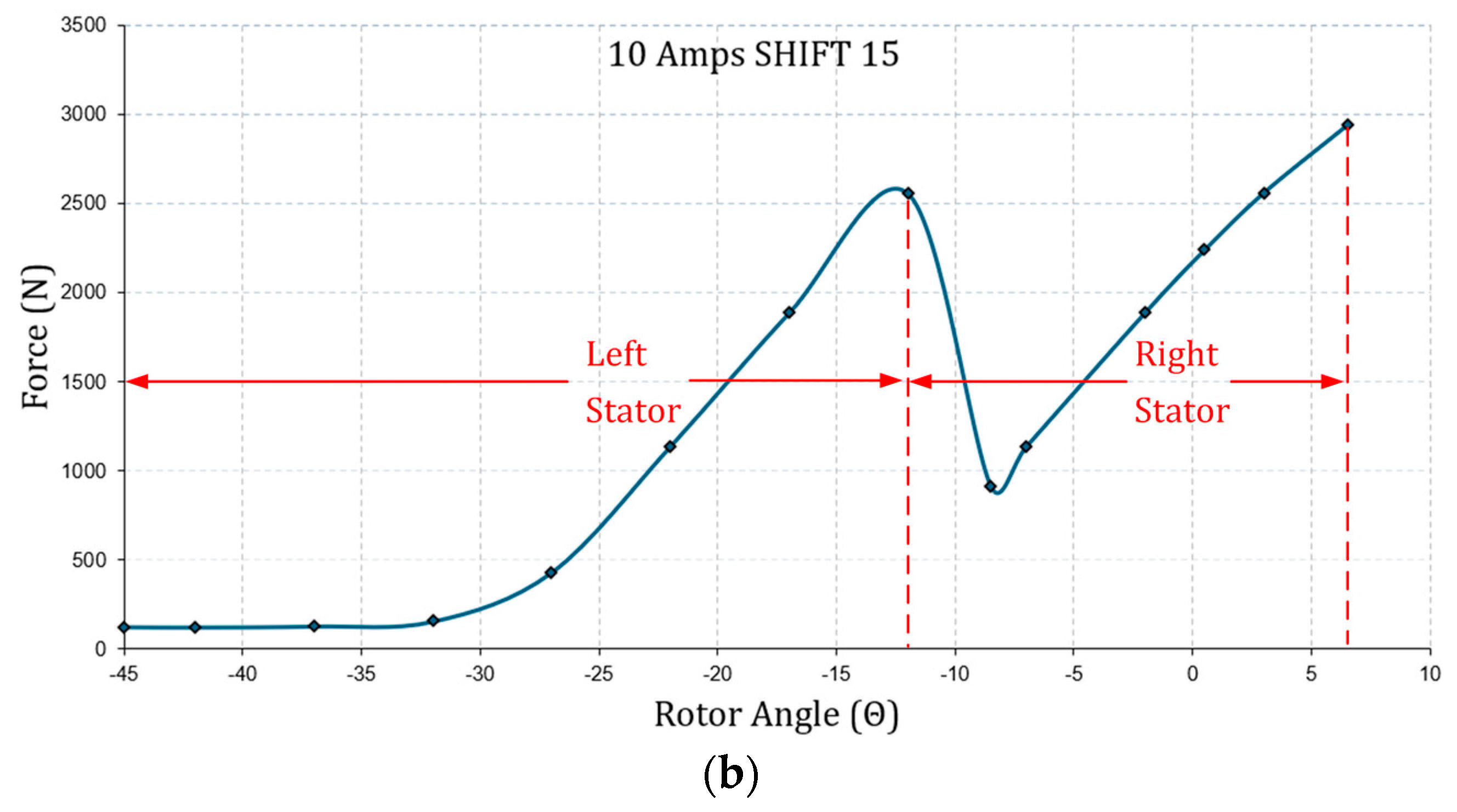
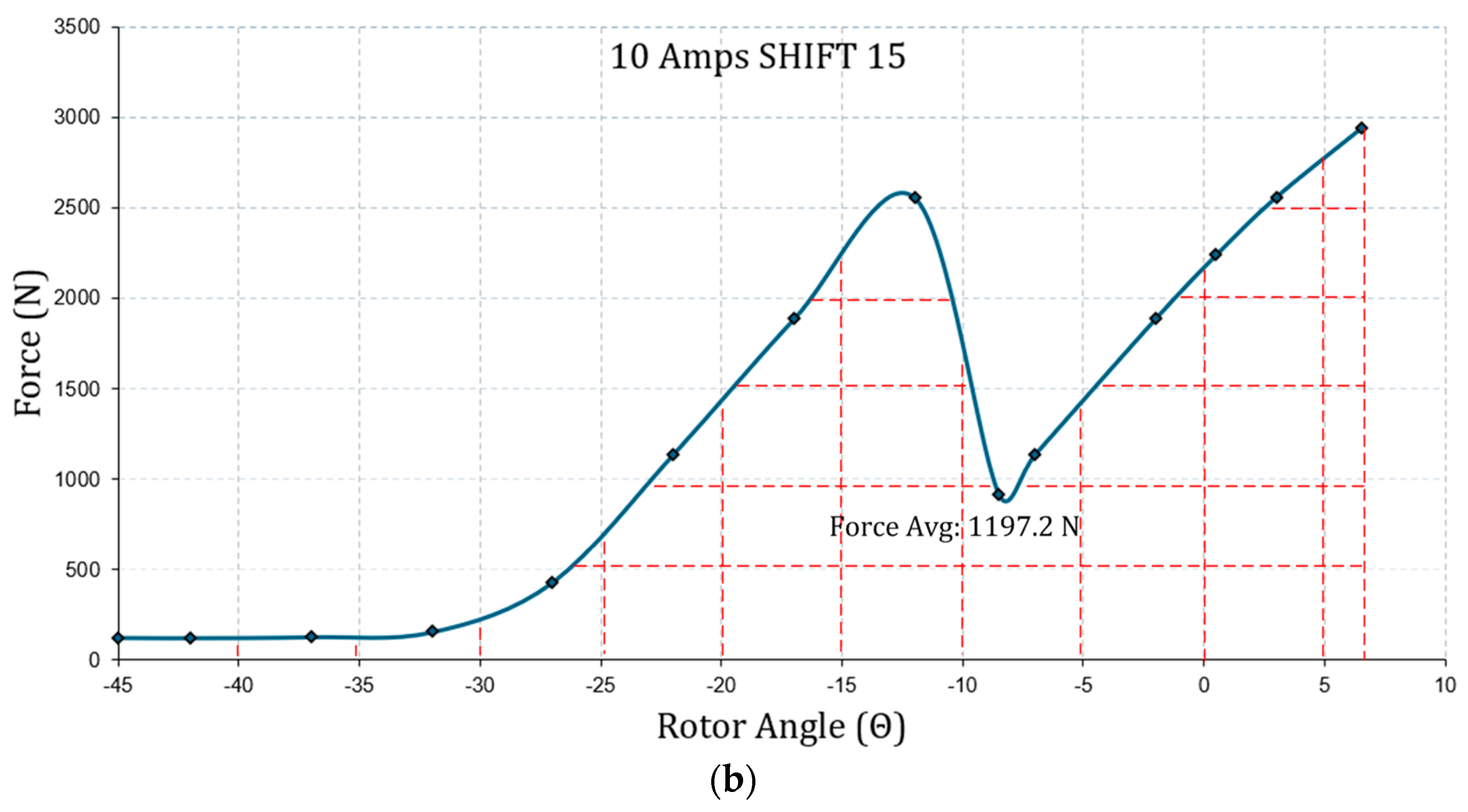
| 10 | 9.63 | 18.42 | 1197.2 |
| 12.5 | 10.06 | 23.85 | 1355.6 |
| 15 | 10.34 | 28.52 | 1503.6 |
| Single-Stator and Single-Rotor FP-AFSRM | |||
|---|---|---|---|
| Current (Amps) | Trip (%) | Tavg (Nm) | Favg (N) |
| 5 | 34.82 | 5.13 | 956.8 |
| 7.5 | 43.17 | 9.56 | 1305 |
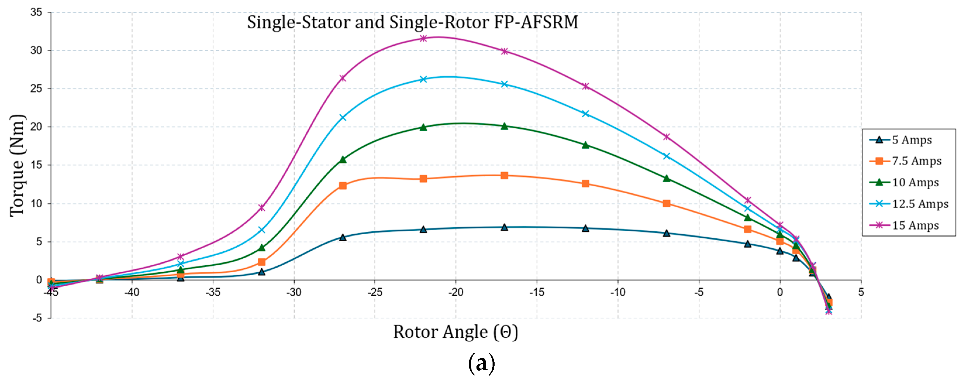
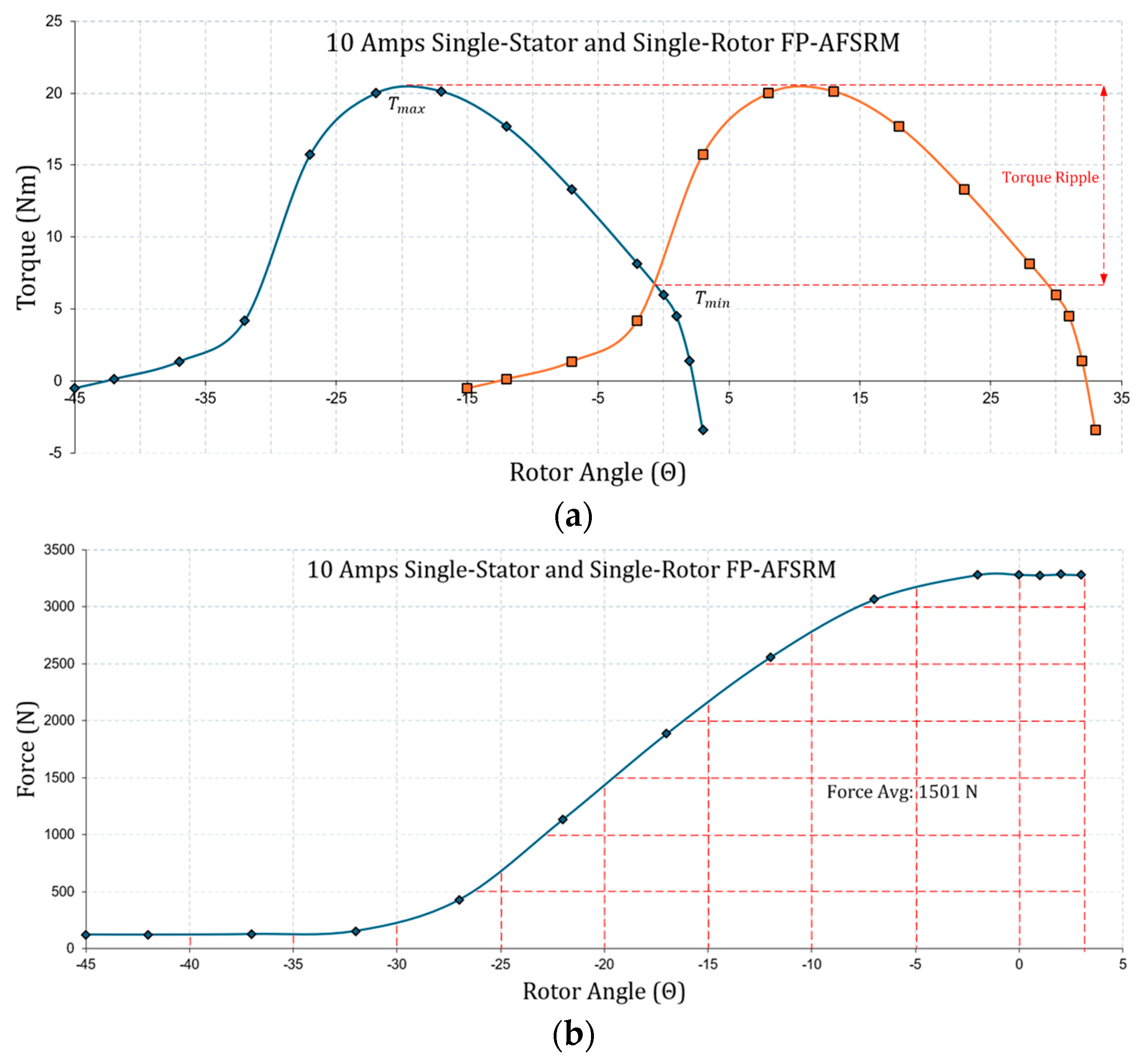
| 10 | 48.98 | 13.50 | 1501 |
| 12.5 | 51.14 | 17.36 | 1671.2 |
| 15 | 51.48 | 20.84 | 1825.2 |
| Single-Stator and Single-Rotor FP-AFSRM | Proposed Double-Sided Rotor and Stator FP-AFSRM | |||||||||
|---|---|---|---|---|---|---|---|---|---|---|
| Current (Amps) | Trip (%) | Tavg (Nm) | Favg (N) | Current (Amps) | Trip (%) | Tavg (Nm) | Favg (N) | Δ %Trip | ΔTavg (%) | ΔFavg (%) |
| 5 | 34.82 | 5.13 | 956.8 | 5 | 4.40 | 6.63 | 713.7 | −30.42 | 29.23 | −25.4 |
| 7.5 | 43.17 | 9.56 | 1305 | 7.5 | 4.91 | 13.03 | 1025 | −38.25 | 36.26 | −21.45 |
| 10 | 48.98 | 13.50 | 1501 | 10 | 9.63 | 18.42 | 1197.2 | −39.35 | 36.43 | −20.23 |
| 12.5 | 51.14 | 17.36 | 1671.2 | 12.5 | 10.06 | 23.85 | 1355.6 | −41.08 | 37.32 | −18.88 |
| 15 | 51.48 | 20.84 | 1825.2 | 15 | 10.34 | 28.52 | 1503.6 | −41.14 | 36.85 | −17.61 |
Disclaimer/Publisher’s Note: The statements, opinions and data contained in all publications are solely those of the individual author(s) and contributor(s) and not of MDPI and/or the editor(s). MDPI and/or the editor(s) disclaim responsibility for any injury to people or property resulting from any ideas, methods, instructions or products referred to in the content. |
© 2024 by the author. Licensee MDPI, Basel, Switzerland. This article is an open access article distributed under the terms and conditions of the Creative Commons Attribution (CC BY) license (https://creativecommons.org/licenses/by/4.0/).
Share and Cite
Sahin, C.A. Reduction of Torque Ripple and Axial Force in a Fully Pitched Axial Flux Switched Reluctance Motor Using a Double Stator Structure. Appl. Sci. 2024, 14, 8658. https://doi.org/10.3390/app14198658
Sahin CA. Reduction of Torque Ripple and Axial Force in a Fully Pitched Axial Flux Switched Reluctance Motor Using a Double Stator Structure. Applied Sciences. 2024; 14(19):8658. https://doi.org/10.3390/app14198658
Chicago/Turabian StyleSahin, Cihan Alp. 2024. "Reduction of Torque Ripple and Axial Force in a Fully Pitched Axial Flux Switched Reluctance Motor Using a Double Stator Structure" Applied Sciences 14, no. 19: 8658. https://doi.org/10.3390/app14198658