Article

Performance Assessment of Flat Plate Solar Collector Using Simple and Hybrid Carbon Nanofluids at Low Thermal Capacity

by
José Michael Cruz
1,2,
Sandra Angélica Crepaldi
1,
Geydy Luz Gutiérrez-Urueta
3,
José de Jesús Rubio
1,
Alejandro Zacarías
1,*,
Cuauhtémoc Jiménez
1,2,
Guerlin Romage
1,
José Alfredo Jiménez
4,
Abel López
1 and
Ricardo Balcazar
5
1
Instituto Politécnico Nacional, Academia de Térmicas/SEPI ESIME Azcapotzalco, Mexico City 02550, Mexico
2
Tecnológico Nacional de México, Instituto Tecnológico de Apizaco, Tlaxcala 90300, Mexico
3
Facultad de Ingeniería, Universidad Autónoma de San Luis Potosí, San Luis Potosí 78290, Mexico
4
Instituto Politécnico Nacional, UPALM, Mexico City 07000, Mexico
5
Tecnológico de Estudios Superiores de Coacalco (TESCo), Mexico City 55700, Mexico
*
Author to whom correspondence should be addressed.
Appl. Sci. 2024, 14(19), 8732; https://doi.org/10.3390/app14198732
Submission received: 1 August 2024 / Revised: 9 September 2024 / Accepted: 24 September 2024 / Published: 27 September 2024
(This article belongs to the Section Energy Science and Technology)

Abstract

:

Featured Application

Use of renewable energies with nanotechnology.

Abstract

Installation of flat solar collectors (FSCs) has been increasing due to the zero cost of renewable energy. However, the performance of this equipment is limited by the area, the material and the thermophysical properties of the working fluid. To improve the properties of the fluid, metal and metal oxide nanoparticles have mainly been used. This paper presents the performance assessment of the FSCs using simple and hybrid carbon nanofluids of low thermal capacity. Energy and mass balance modeling was performed for this study. A parametric analysis was conducted to examine the impact of key variables on the performance of the solar collectors using simple graphite and fullerene nanofluids, as well as hybrid metal–oxide–carbon nanofluids. From the results of heat transfer in FSCs, using graphite and fullerene nanofluids, it can be concluded that adding these nanoparticles improves the convection coefficient by 40% and 30%, respectively, with 10% nanoparticles. The graphite and fullerene nanoparticles can enhance the efficiency of FSCs by 2% and 1.5% more than base fluid. As the decrease in efficiency using fullerene with magnesium oxide is less than 0.2%, fullerene hybrid nanofluids could still be used in FSCs.

1. Introduction

The deployment of flat solar collectors (FSCs) has been growing steadily thanks to the no-cost nature of renewable energy. Studies such as the one carried out by [1] shows that the efficiency of the solar collector is influenced by the solar radiation and the temperature of the thermal fluid. However, the performance of this equipment is limited by the area, the material and the thermophysical properties of the working fluid. The primary characteristics required for working fluids in solar collectors include a high boiling point, non-corrosiveness, high heat capacity, and high thermal conductivity (TC). Traditionally, water, oil, and ethylene glycol have been the most used fluids in solar collectors. To improve the properties of the fluid, metallic and metal oxide nanoparticles in simple and hybrid nanofluids have mainly been used.
Composed of only one type of particle, simple nanofluids exhibit significantly higher TC than conventional fluids. They have demonstrated notable improvements in heat transfer for applications such as heat exchangers, refrigeration systems, and solar thermal systems. Choi and Eastman [2] defined nanofluids as suspensions of nanometric particles, made of one or more materials, in a base fluid. The concentration of nanoparticles, their shape and size have an impact on the thermophysical characteristics of nanofluids, such as TC, viscosity, heat capacity, as well as on the heat transfer coefficient and optical properties, for example [3]. Colloidal suspensions of nanomaterials (metals, metal oxides, and carbon) provide greater TC, better stability, and less risk of clogging in pipes [4,5]. Larger nanoparticles can cause suspension instability, resistance to flow, clogging of pipes and abrasion problems.
A hybrid nanofluid is a combination of physical and chemical properties, consisting of adding two or more types of nanoparticles to a base fluid. These nanoparticles can be made of different materials such as metal oxides, carbon, polymers and other synthetic materials. The main characteristics of hybrid nanofluids are their high TC, low viscosity, and ability to improve the absorption of solar radiation [6,7]. A literature review of metal oxide and carbon nanofluids used in FSCs is presented below.

1.1. Metal Oxide Nanofluids in FSCs

The TC and heat transfer of a fluid improve with the use of metal oxide nanoparticles, as shown by [8]. The nanofluids used were aluminum oxide (Al2O3), magnesium oxide (MgO), cerium oxide (CeO2), titanium dioxide (TiO2), zinc oxide (ZnO) and iron oxide (Fe2O3). In [9], the thermophysical characteristics of nanofluids, such as viscosity, TC and heat transfer with nanoparticles of (SiO2), (Al2O3), (ZrO2), (TiO2), and (CuO) have been experimentally evaluated. The researchers have shown that viscosity increases with decreasing the nanoparticle size, while thermal conductivity increases as the particle size increases. Yousefi et al. [10] carried out an experimental investigation in which they studied the effects of the thermophysical properties of the Al2O3/water nanofluid on the efficiency of an FPSC. The authors showed that the efficiency of the solar collector increased by 28.3%. Verma et al. [11] carried out an experimental study of energy and exergy, using MgO-H2O nanofluid in concentrations of 0.25 to 1.50 vol%. The authors found that at higher concentrations of nanoparticles, when agglomeration occurs, the Brownian movement between the nanoparticles and the molecules of the base fluid decreases, which causes a reduction in the convective heat transfer between the base fluid and the nanoparticles. Sint et al. [12] estimated the thermal efficiency of an FSC using CuOH2O. Efficiency was improved by 5% with a volume percentage of 2 vol% and a nanoparticle size of 25 nm. The performance is proportional to the volume fraction of the nanoparticles in the base fluid, as described by [13]. Alawi et al. [5] carried out studies with metallic and metal oxide nanoparticles to operate FSCs.
Suresh et al. [6] demonstrated that the use of hybrid nanofluids can enhance TC compared to single nanofluids by preparing a hybrid Al2O3-Cu nanofluid using the hydrogen reduction technique in a 90:10 ratio of Al2O3-to-CuO nano powder. Measurements on TC and viscosity showed that the increase in viscosity is more pronounced than the conductivity with respect to concentration. The highest conductivity gain was recorded at 12.11% for a 2% volume concentration. Madhesh and Kalaiselvam [4] prepared hybrid nanofluid by mixing surface-modified (crystalline) copper–titanium nanocomposites, with a particle range of 0.1% to 2% (vol.%) and mean nanoparticle size of 55 nm. The results confirm the improvement in surface conductance (hs) from 0.52 to 1%. Hemmat et al. [14] found the increasing effect of nanoparticle concentration on the TC of the Ag-MgO–water nanofluid with the same concentration ratio.

1.2. Carbon Nanofluids in FSCs

The use of carbon nanoparticles is of great interest, mainly due to their reduced weight, greater hardness, high TC, high heat absorption capacity and large surface area. The use of carbon nanoparticles has the additional benefit of having high TC, extreme durability and resistance to corrosion. CNTs made from sheets of graphene that have been rolled up can be found as single-walled carbon nanotubes (SWCNTs) and multi-walled carbon nanotubes (MWCNTs).
Ahmadi et al. [15] carried out a study in which they dispersed graphene in the base fluid to increase the thermal efficiency of a solar collector. Alawi et al. [16] examined the thermophysical properties of nanofluids composed of carbon nanoparticles and metal oxides. The authors used different nanoparticles such as graphene, CNT, Al2O3, and SiO2. It was found that as more nanoparticles are added to the fluid, the viscosity of the fluid increases. It was observed that the addition of Al2O3 and SiO2 nanoparticles slightly increases the heat capacity of the nanofluids. The findings that the authors showed imply that the most successful nanoparticles for improving the TC of nanofluids are carbon nanotubes and graphene. While the addition of Al2O3 and SiO2 nanoparticles can increase the heat capacity, Tong et al. [17] studied the influence of different types of nanoparticles on the efficiency of an FSC, where they used four types of nanoparticles, MWCNTs, CuO, Fe3O4, and Al2O3, to evaluate the thermophysical properties, such as their density, viscosity and TC, as well as the efficiency of a solar collector. The findings demonstrated that, compared to the base fluids, the MWCNT nanoparticles increased the efficiency of the solar collector. It was found that as the CuO concentration increased, the efficiency of the solar collector increased. It was found that the addition of Fe3O4 increases the efficiency of the solar collector. Although the TC of Fe3O4 is high, its low concentration in the nanofluids limited its effect on the efficiency of the solar collector.
Verma et al. [13] evaluated the thermal efficiency of FPSCs using CuO-MWCNT and MgO-MWCNT hybrid nanofluids with water. The efficiency of the FSCs with MgO hybrid nanofluids improved by 25.1% compared to the base fluid and by 16.28% with respect to the MgO/water nanofluid. To the extent that the literature review has been possible, Table 1 presents the simple and hybrid metal oxide and carbon nanofluids that have been used in FSCs until now.
As can be seen in Table 1, the carbon nanoparticles that have been used until now in FSCs are those of graphene in its spherical form and in multi-walled and single-walled carbon nanotubes. However, it has been found that graphite has been used to improve the efficiency of evacuated tube, dish parabolic and linear parabolic solar collectors by [19,20,21], respectively. Likewise, it has been found that fullerene C60 has been used to improve the efficiency in flat photovoltaic/thermal and direct absorption solar collectors by [22,23], respectively.
As shown in this section, several studies have explored the use of simple and hybrid nanofluids in thermal solar collectors. However, there is a notable gap in the literature regarding the application of simple graphite and fullerene C60 nanofluids, as well as hybrid carbon nanofluids. This work aims to develop a mathematical model to simulate the behavior of FSCs using metal oxide and carbon nanoparticles, along with hybrid metal–oxide–carbon nanofluids. The study evaluates the effect of nanoparticle concentration and compares the performance of solar collectors using simple and hybrid nanofluids. A parametric analysis is conducted to examine the impact of key variables on the performance of the solar collectors. The results will assess the potential of hybrid carbon nanofluids in enhancing the efficiency of FSCs. Additionally, this research may serve as a foundation for future studies on the application of nanofluids in other thermal energy systems.

2. Materials and Methods
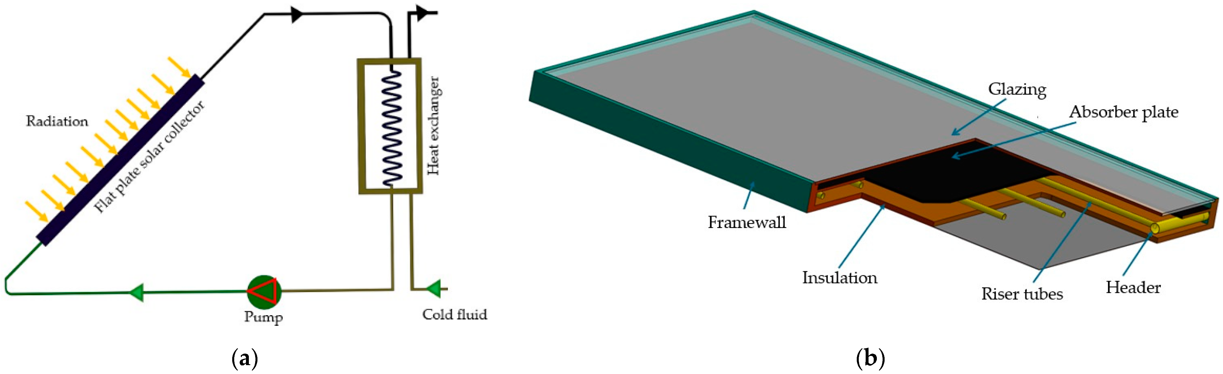
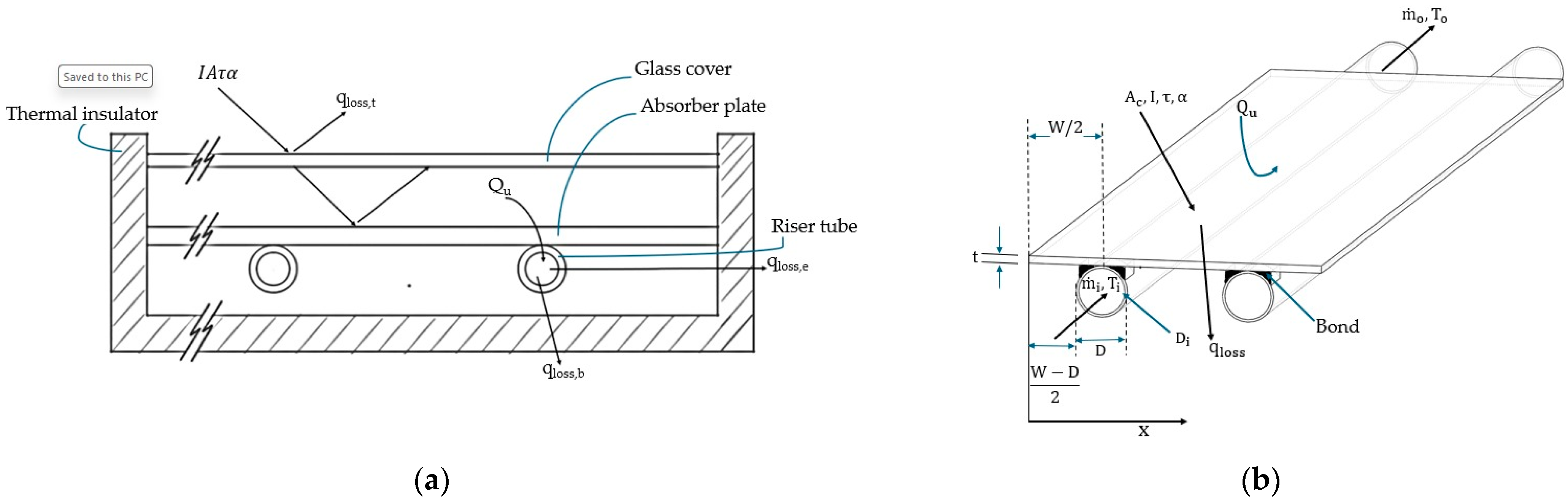
Mathematical modeling, its validation and the simulation of simple nanofluids and hybrid nanofluids in FSCs are presented in this section.

2.1. Phisical Model

The mathematical modeling was carried out on an FSC; Figure 1a shows the solar collector coupled to a heat exchanger. A pump is also depicted, which helps circulate the working fluid throughout the system. Figure 1b presents a section of the collector, highlighting the main geometric parameters, including the absorber composed of the riser tubes and the absorber plate, the glass cover, and thermal insulation. The specifications are detailed in Section 2.3.

2.2. Mathematicl Modeling

The cross-sectional view of an FSC, as shown in Figure 1b, is presented in Figure 2a. This figure illustrates the main parameters, such as solar radiation, useful heat, and heat losses involved in the heat transfer process of a flat plate solar collector. These parameters are represented in a thermodynamic system, as shown in Figure 2b, which includes geometric, thermodynamic, and fluid flow parameters. These are used to develop the mathematical modeling of an FSC operating with simple and hybrid carbon nanofluids.

2.2.1. Governing Equations

By applying the first law of thermodynamics to the control volume in Figure 2b, we have
Q ˙ W ˙ = o m ˙ k h + g z + w 2 2 k i m ˙ k h + g z + w 2 2 k ,
where Q ˙ and W ˙ are the heat flux and mechanical power developed by the thermodynamic system, respectively. m ˙ o and m ˙ i are the mass flow rates at the system’s outlet and inlet. h, z, and v are the enthalpy, height, and fluid velocity, respectively, and g is gravity.
The energy flow in the thermodynamic system, according to the first law of thermo-dynamics, can be represented as
I c A c τ s α s = q u + q l o s s + d e c d t ,
where τ and α are the transmittance and absorptance of the transparent cover. q u and q l o s s are the useful heat and heat losses of the solar collector. The third term of Equation (2) represents the change in the system’s energy over time.
The useful heat absorbed by the working fluid, Q u , according to [24], is given by
Q u = m ˙ C p ( T o T i ) ,
where Cp is the specific heat of the fluid, and To and Ti are the outlet and inlet temperatures of the system, respectively.
The useful heat can also be determined as the difference between the useful heat and the heat lost from the solar collector, according to [24]:
Q u = F R A c G T τ α U L T i T a ,
where FR and UL are the heat removal factor and the overall loss coefficient, GT is the irradiance, τ α is transmittance absorptance and Ta is the ambient temperature.
The instantaneous collector efficiency, ηc, is determined by [25]
η = Q u A c I = m ˙ C p ( T o T i ) A c I ,
η = F R τ α F R U L T i T a G T ,

2.2.2. Heat Removal and Collector Efficiency Factors

The heat removal factor, FR, is determined as
F R = m ˙ C p A C U L 1 e x p U L F A C m ˙ C p ,
The collector efficiency factor, F’, is calculated by the equation shown by [26]
F = 1 U L W 1 U L D o + W D o F + 1 C b + 1 π D i n h i ,
where W, Din, Do represent the distance between the fins, the internal and external diameters of the pipes, respectively.
The conductance at the C b junctions is calculated by the equation:
C b = k b b γ ,
where kb and b represent the TC and the length of the junction, while γ represents the average thickness of the junction.
The standard fin efficiency, F, is determined by
F = tanh m W D o 2 m W D o 2 ,
To calculate m, the following equation is used:
m = U L k C δ C ,
where kc and δc are, respectively, the TC and the thickness of the absorber.

2.2.3. Convection Heat Transfer Coefficient

The convective heat transfer coefficient hfi is determined by
h i = N u k D i ,
where the Nusselt number is determined, as suggested by [12]:
N u = 0.4328 ( 1 + 11.285 ϕ 0.754 P e 0.218 ) R e 0.333 P r 0.4 , laminar flow
N u = 0.0059 ( 1 + 7.6286 ϕ 0.6886 P e 0.001 ) R e 0.9238 P r 0.4 , turbulent flow
This relationship is valid for (Re ≤ 2300 for laminar flow and Re > 2300 for turbulent flow).
The dimensionless Reynolds and Prandtl numbers were determined as (where Nt is rise tube number)
R e = 4 m ˙ π D μ N t
P r = μ C p k

2.2.4. Overall Heat Loss Coefficient

The overall coefficient of losses, UL, is calculated by
U L = U t + U b + U e ,
where Ut, Ub, Uθ are the upper, lower and lateral loss coefficients, respectively. The upper loss coefficient, Ut, is determined as a sample [27]:
U t = 1 N C T P T P T a N + f 0.33 + 1 h a + σ T P + T a T P 2 + T a 2 ε p + 0.5 N 1 ε p + 2 N + f 1 ε g ,
where
C = 365.9 × 1 0.00883 β + 0.0001298 × β 2 ,
f = 1 + 0.04 h a 0.0005 h a 2 × 1 + 0.091 N ,
h a = 5.7 + 3.8 V a ,
where Va is the wind speed, N is the number of covers, εp is the emissivity of the plate, εg is the emissivity of the roof, and β is the angle of inclination of the collector, respectively.
The lower loss coefficient, Ub, is determined from
U b = k b x b ,
where kb, xb are the TC and the thickness of the lower insulation, respectively.
The loss coefficient at the edges is calculated with the following equation:
U e = A e A C ,

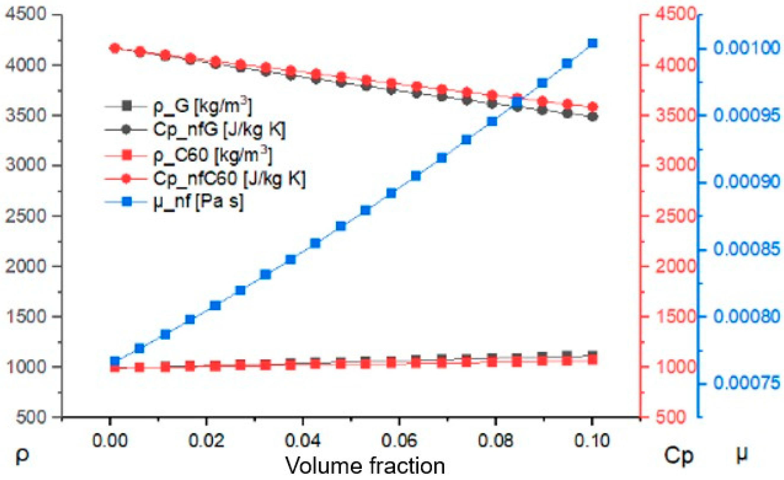
2.2.5. Simple Nanofluid Properties

The thermophysical properties of nanofluids were determined based on the methods outlined in the relevant studies. The density of the nanofluid is determined as proposed by [3,5]
ρ n f = 1 ρ b f + ρ n p ,
The viscosity of the nanofluid is determined as proposed by [3], and shown in [5] through
μ n f = 1 + 2.5 + 6.2 ϕ 2 μ b f
The specific heat of the nanofluid was determined as suggested by [5] using the equation:
C p n f = C p b f ρ b f 1 + C p n p ρ n p ρ n f ,
where Cp, ρ, are the specific heat, density and volume fraction, respectively. The subscripts nf, np, bf refer to nanofluid, nanoparticle, and base fluid, respectively.
The Brownian movement of nanoparticles was considered by [5,28,29] and here, to estimate the TC of the nanofluid, knf, with spherical nanoparticles:
k n f = k n p + 2 k b f 2 k b f k n p k n p + 2 k b f + k b f k n p + ρ n p ϕ C p n p 2 k n f k B T m 3 π r c μ n f k b f ,
For cylindrical nanoparticles, the approach by [18,30,31,32] was considered to estimate the TC of the knf, with n = 6:
k n f = k b f   k n p + n 1 k b f + k n p k b f ( k n p + n 1 k b f k n p k b f ) ,

2.2.6. Hybrid Nanofluid Properties

The modeling of the FSC with hybrid nanofluids was conducted using the models presented in Section 2.2.1 and Section 2.2.2, incorporating the thermophysical properties of hybrid nanofluids as detailed in this section. These properties were determined as shown by [33], through
ρ h n f = ζ 1 ρ 1 + ζ 2 ρ 2 ζ 1 + ζ 2 ,
C p h n f = ζ 1 C p 1 + ζ 2 C p 2 ζ 1 + ζ 2 ,
k h n f = ζ 1 k 1 + ζ 2 k 2 ,
where khnf, Cphnf and ρhnf are the total TC, specific heat and density of the nanocomposite; k1 and k2 are the thermal conductivities; Cp1 and Cp2 are the specific heats; ρ1 and ρ2 are the densities; and ζ 1 and ζ 2 are the volume concentrations of each of the used nanoparticles.

2.3. Model Validation
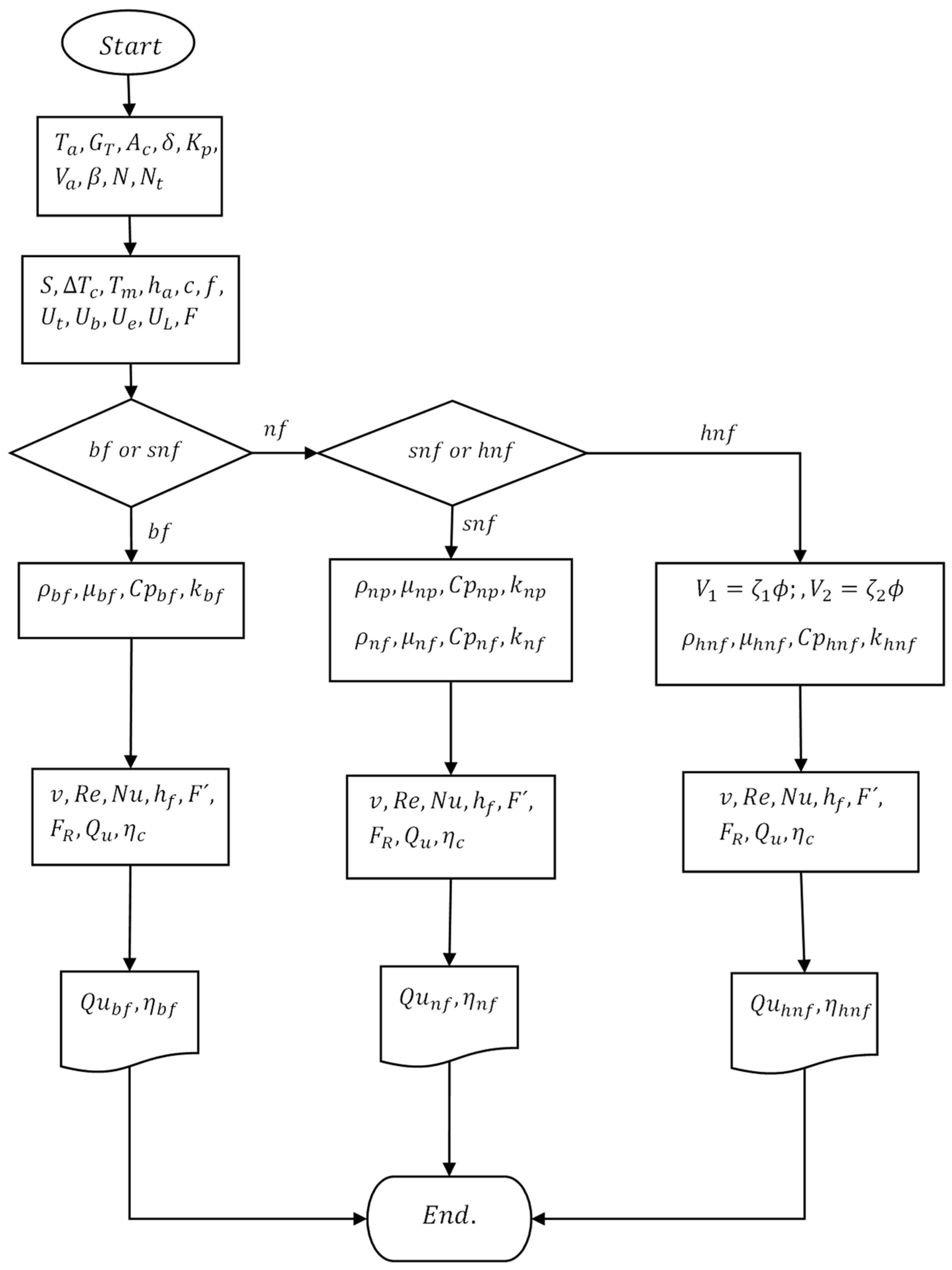
The validation of the model was carried out with the collector specifications shown in Table 2, and taken from [34] by comparing the results obtained in this work on useful heat and efficiency with those published by [34] and shown in Table 3.
The values of radiation, ambient temperature and entrance to the collector were, respectively, 750 W/m2, 23 °C and 25 °C. The error of the results with those of the literature is less than 2%, as can be seen in Table 3.

2.4. Simulation

The model was implemented using Engineering Equation Solver software, EES [36]. This software has integrated the thermophysical properties of various substances and can be programmed in a user-friendly environment. The simulation procedure is illustrated in Figure 3. The properties of the base fluid were obtained from the data provided by [37], while the properties of the nanoparticles were assigned as shown in Table 4. The various parameters used in the simulation are listed in Table 5.

Assumptions

The assumptions made in the simulation are as follows:
  • Fully developed flow and stable conditions.
  • The ambient temperature at the top and bottom of the collector are the same.
  • Negligible addition to the collector surface by the header.
  • In all pipes, the fluid is in uniform flow.

3. Results and Discussion

The results obtained through the simulation are presented in this section for FSCs operating with simple and hybrid carbon nanofluids (graphite and fullerene, C60). The ambient temperature and radiation used are 23 °C and 750 W/m2, respectively.
In Figure 4, the useful heat and collector efficiency are shown. From the figure, for this range of mass flow, the useful heat obtained was between 450 and 580 W, while for the efficiency, it was between 53% and 69%. These results were similar to those reported by [34,35,40].

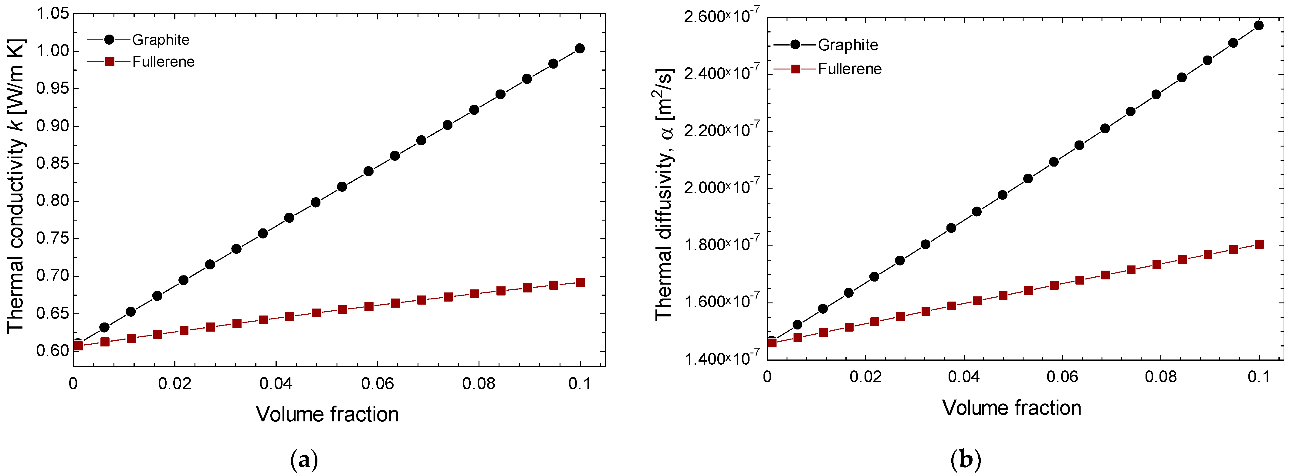
3.1. FSCs with Graphite and Fullerene Nanofluids

This section presents the thermophysical properties of nanofluids with respect to volume fraction. The carbon nanofluids evaluated are graphite, G, fullerene, C60, and multi-walled carbon nanotubes (MWCNTs).
Figure 5 shows the change in densities, viscosity and specific heat capacity for graphite and fullerene nanofluids. It is observed that the density and viscosity of nanofluids increases with the volume fraction to 10.81% and 6.76% for the density and 26.62% for the viscosity for the graphite and fullerene, respectively. Specific heat capacities decrease to 16.28% and 13.93% for the graphite and fullerene, respectively, with increasing volume fraction.
According to [41], the improvement in TC depends largely on the volume fraction of solids and, to some extent, on temperature. Figure 6a shows that the TC of graphite nanofluids increases with the volume fraction to 39.16% and 12.25% for the graphite and fullerene, respectively. This is true for nanofluids containing G, which have higher TC levels compared to the base fluid. However, for the fullerene nanofluid, C60, TC tends to increase at a lower rate because C60 nanoparticles have a TC of 0.4 W/mK (see Table 2), which is lower than that of the base fluid, which has a TC of 0.605 W/mK. In Figure 6b, the thermal diffusivity of graphite and fullerene nanofluids is shown to increase with the volume fraction to 44.53% and 19.33% for the graphite and fullerene. At a volume fraction of 0.1, carbon nanofluids such as G have diffusivity greater than 2.000 × 10⁻⁷ m2/s, while for C60, the change in thermal diffusivity is minimal, with a value of 1.503 × 10⁻⁷ m2/s at a volume fraction of 0.1.
Figure 7a presents the Reynolds numbers for the base fluid (water) and nanofluids (graphite and fullerene) as functions of mass flow rate and volume fraction, respectively. The figure demonstrates that the Reynolds number for the base fluid increases from 200 to 2100 as the mass flow rate rises. Conversely, the Reynolds number for carbon-based nanofluids decreases from 1700 to 1300 as the volume fraction increases. This discrepancy arises because the density and viscosity of the nanofluids increase. Figure 7b illustrates the Prandtl number Pr for graphite and fullerene nanofluids as a function of volume fraction. The figure shows that as the volume fraction increases, there is no significant change in the Prandtl number of the fullerene. On the other hand, the Pr of graphite nanofluids decreases. This discrepancy arises because the conductivity of the fullerene decreases.
Figure 8 illustrates the Nusselt number (Nu) and the convection heat transfer coefficient (h) for graphite, fullerene and multiple-walled carbon nanotube nanofluids as a function of volume fraction. The figure shows that as the volume fraction increases, both the Nu and h increase. Notably, the Nu for fullerene is higher compared to graphite and MWCNTs, but the h for fullerene is lower than that of graphite and MWCNTs across the evaluated volume fractions. This discrepancy arises because fullerene has lower TC levels than graphite. From the figure, the use of graphite and fullerene nanofluids improve the convection heat transfer coefficient by up to 40% and 30%, respectively, with 10% nanoparticles.

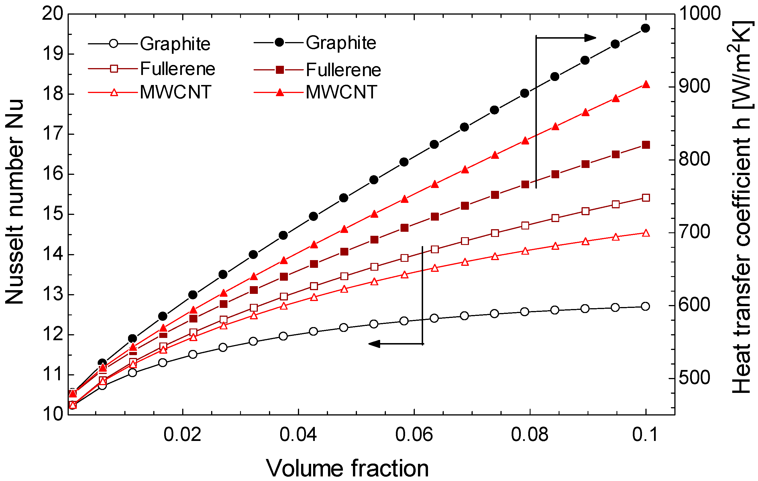
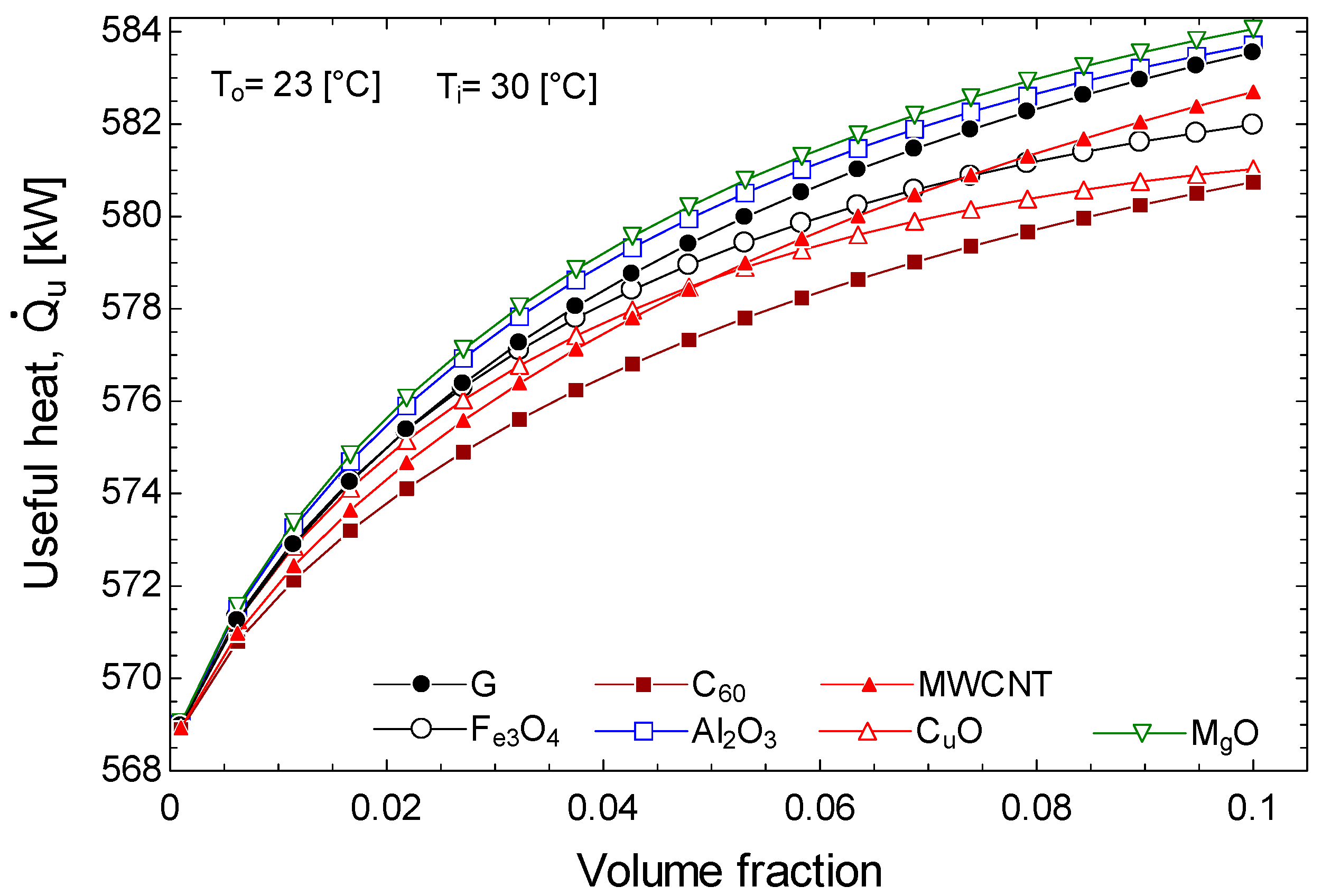
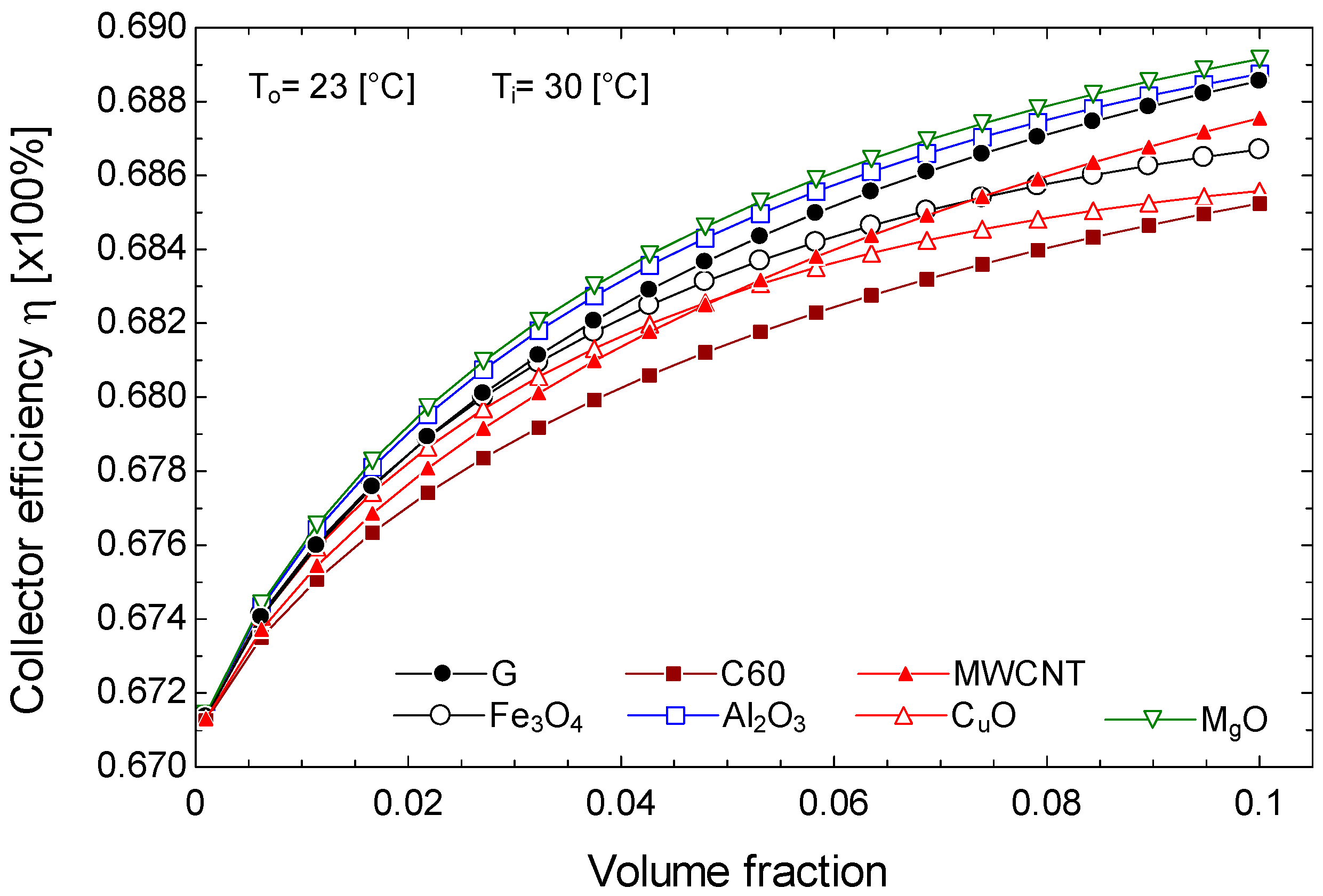
3.2. FSCs with Simple Metal Oxide and Carbon Nanofluids

This section presents the evaluation of the useful heat and efficiency of an FSC with metal oxide and carbon nanofluids. The metal oxide nanofluids evaluated are those already known, ferrous oxide, Fe3O4; aluminum oxide, Al2O3; copper oxide, CuO; and magnesium oxide, MgO. Meanwhile, the carbon nanofluids evaluated are graphite, G, and fullerene, C60. The latter are also compared with the results of the already widely studied nanofluids of multi-walled carbon nanotubes, MWCNTs.
Figure 9 and Figure 10 present the useful heat output and the efficiency, respectively, of the FSCs with respect to the volume fraction of the nanofluids. Both parameters increase with the addition of nanoparticles for all the nanofluids studied. For instance, at ϕ = 0.1, aluminum and magnesium metal oxide nanofluids provide approximately 1% more useful heat than ferrous and copper metal oxide nanofluids. Additionally, both the useful heat generated by the fullerene nanofluid, and the efficiency, exceed that of ferrous oxide and cuprous oxide nanofluids. Graphite demonstrates the highest useful heat output among all evaluated nanofluids. This and fullerene nanoparticles can enhance the efficiency of FSCs by 2% and 1.5%. The superior values observed of the carbon nanofluids, in addition to the diameter of the nanoparticles, is primarily attributed to their thermal diffusivity (α = k/ρCp), which counteracts the storage effect and compensates for the low specific heat, high density, and viscosity values, as well as the low conductivity of fullerene.

3.3. FSCs with Hybrid Carbon Nanofluids

As shown in Section 3.2, the simple carbon nanofluids evaluated in this study per-form similarly to the simple metal oxide nanofluids of aluminum (Al2O3) and magnesium (MgO). Consequently, to visualize the improvement in the performance of FSCs using combinations of metal oxide nanoparticles with the carbon nanoparticles evaluated here, this section presents results from the evaluation of hybrid nanofluids based on graphite and fullerene combined with Al2O3 and MgO nanoparticles.
Figure 11 and Figure 12 show the useful heat and the efficiency, respectively, of the FSCs using carbon hybrid nanofluids with respect to volume fraction. From these figures, it can be seen that both parameters increase when the volume fraction increases in all cases. However, when metal oxide nanoparticles are added to carbon nanoparticles, at the volume fraction of 0.1, both the useful heat and the efficiency decrease to 0.85% for G-Al2O3–water and G-Al3O2–water hybrid nanofluids. While the C60-Al3O2–water and C60-MgO–water hybrid nanofluids decrease to 0.48% and 0.56%, respectively. This behavior has also been observed by authors such as Verma et al. [13], where the addition of magnesium and copper nanoparticles reduced the efficiency of the collector with carbon nanotubes. This may be due to the pressure drop and irreversibilities, as the authors have noted.
From the evaluation of FSCs using hybrid carbon nanofluids presented here, it can be concluded that while the performance of the solar collector is not significantly improved, the density of the nanofluid decreases, which reduces the pressure drop in fluid flow. As the decrease in efficiency using fullerene with magnesium oxide is less than 0.85%, fullerene hybrid nanofluids could still be used in FSCs.

4. Conclusions

The density and viscosity of nanofluids increase with volume fraction. Graphite nanofluids showing a greater increase in density compared to fullerene nanofluids. Specific heat capacities decrease as the volume fraction increases, with the base fluid (H₂O) exhibiting a higher specific heat capacity at zero volume fraction compared to the corresponding nanofluids with graphite and fullerene nanoparticles. TC generally increases with volume fraction; however, for the fullerene nanofluid (C60), TC decreases due to the lower TC of C60 nanoparticles (0.4 W/mK) compared to the base fluid (0.605 W/mK). Thermal diffusivity of both graphite and fullerene nanofluids increases with volume fraction. Additionally, as volume fraction increases, both the Nusselt number and the convection coefficient increase. Notably, the Nusselt number for fullerene is higher compared to graphite, but the convection coefficient for fullerene is lower than that of graphite across the evaluated volume fractions. This discrepancy is attributed to the lower TC of fullerene compared to graphite. From the evaluation of heat transfer in FSCs, using graphite and fullerene nanofluids, it can be concluded that adding these nanoparticles improves the convection coefficient by 40% and 30%, respectively, with 10% nanoparticles.
From the performance results of the FSCs, it can be concluded that graphite and fullerene nanoparticles can enhance the efficiency of FSCs by 2% and 1.5% more than base fluid. From the evaluation of FSCs using hybrid carbon nanofluids presented here, it can be concluded that while the performance of the solar collector is not significantly improved, the density of the nanofluid decreases, which reduces the pressure drop in fluid flow. As the decrease in efficiency using fullerene with magnesium oxide is less than 0.85%, fullerene hybrid nanofluids could still be used in FSCs.

Author Contributions

Conceptualization, J.M.C., S.A.C., C.J. and A.Z.; methodology, J.M.C., S.A.C., C.J. and A.Z.; software, J.M.C., S.A.C., J.d.J.R., R.B. and A.Z.; validation, G.R., J.d.J.R., R.B., A.L. and A.Z.; formal analysis, J.M.C., S.A.C., G.L.G.-U. and A.Z.; investigation, J.M.C., S.A.C., G.R., J.A.J. and A.Z.; re-sources, C.J., G.R., J.A.J. and A.Z.; data curation, J.M.C., S.A.C., G.L.G.-U., C.J., G.R. and A.Z.; writing—original draft preparation, J.M.C., S.A.C., C.J. and A.Z.; writing—review and editing, J.M.C., S.A.C., G.L.G.-U., C.J., J.d.J.R., A.L. and A.Z.; visualization, G.R., J.d.J.R. and A.L.; supervision, A.Z. and G.L.G.-U.; project administration, A.Z.; funding acquisition, G.R., J.d.J.R., J.A.J. and A.Z. All authors have read and agreed to the published version of the manuscript.

Funding

This study was provided financial support from the science research grant SIP20240435, from the Instituto Politécnico Nacional, IPN; it is greatly appreciated.

Institutional Review Board Statement

Not applicable.

Informed Consent Statement

Not applicable.

Data Availability Statement

The original contributions presented in the study are included in the article, further inquiries can be directed to the corresponding author.

Acknowledgments

The authors also acknowledge the financial support given to the postgraduate students by the National Board of Science and Techmology, CONACYT, of Mexico.

Conflicts of Interest

The authors declare no conflicts of interest.

Nomenclature

Aarea (m2), absorber
bjoint length (m)
Cconductance (W/m K)
Cpheat capacity (kJ/kg K)
D diameter (m)
F standard fin efficiency
F R heat removal factor
F solar collector efficiency factor
h heat transfer coefficient (W/m2 K)
I solar radiation (W/m2)
k TC (W/m K)
m ˙ mass flow (kg/s)
N u Nusselt number
P r Prandtl number
Q ˙ heat flux (W)
U global heat transfer coefficient (W/m K)
R e Reynolds number
T temperature (K)
W distance between fins (m)
x bottom insulation thickness (m)
Subscripts
a ambient
bjoint between fins and pipes, lower loss
b f base fluid
c absorber
e border surface
g glass
f i internal
h n f hybrid nanofluids
i n inlet, internal
o external
o u t outlet
n f nanofluids
n p nanoparticle
p flat plate
u useful
Greek symbols
α 0 absorptance
β collector inclination angle (°)
δ C absorber thickness (m)
ε emissivity
η efficiency
γ average joint thickness (m)
μ viscosity (Pa s)
volume fraction (%)
ρ density (kg/m3)
σ Stefan Boltzmann’s constant (W/m2 K4)
τ 0 transmittance
θ lateral losses
ζ volume concentration

References

  1. Said, Z.; Saidur, R.; Rahim, N.A. Optical Properties of Metal Oxides Based Nanofluids. Int. Commun. Heat Mass Transf. 2014, 59, 46–54. [Google Scholar] [CrossRef]
  2. Choi, S.U.S.; Eastman, J.A. Enhancing Thermal Conductivity of Fluids with Nanoparticles; Argonne National Lab. (ANL): Argonne, IL, USA, 1995; pp. 1–2. [Google Scholar]
  3. Pak, B.C.; Cho, Y.I. Hydrodynamic and Heat Transfer Study of Dispersed Fluids with Submicron Metallic Oxide Particles. Exp. Heat Transf. 1998, 11, 151–170. [Google Scholar] [CrossRef]
  4. Madhesh, D.; Kalaiselvam, S. Experimental Analysis of Hybrid Nanofluid as a Coolant. Procedia Eng. 2014, 97, 1667–1675. [Google Scholar] [CrossRef]
  5. Alawi, O.A.; Kamar, H.M.; Mallah, A.R.; Mohammed, H.A.; Kazi, S.N.; Che Sidik, N.A.; Najafi, G. Nanofluids for Flat Plate Solar Collectors: Fundamentals and Applications. J. Clean. Prod. 2021, 291, 125725. [Google Scholar] [CrossRef]
  6. Suresh, S.; Venkitaraj, K.P.; Selvakumar, P.; Chandrasekar, M. Synthesis of Al2O3-Cu/Water Hybrid Nanofluids Using Two Step Method and Its Thermo Physical Properties. Colloids Surf. A Physicochem. Eng. Asp. 2011, 388, 41–48. [Google Scholar] [CrossRef]
  7. Kasaeian, A.; Eshghi, A.T.; Sameti, M. A Review on the Applications of Nanofluids in Solar Energy Systems. Renew. Sustain. Energy Rev. 2015, 43, 584–598. [Google Scholar] [CrossRef]
  8. Hendraningrat, L.; Torsæter, O. Metal Oxide-Based Nanoparticles: Revealing Their Potential to Enhance Oil Recovery in Different Wettability Systems. Appl. Nanosci. 2015, 5, 181–199. [Google Scholar] [CrossRef]
  9. Minakov, A.V.; Rudyak, V.Y.; Pryazhnikov, M.I. Rheological Behavior of Water and Ethylene Glycol Based Nanofluids Containing Oxide Nanoparticles. Colloids Surf. A Physicochem. Eng. Asp. 2018, 554, 279–285. [Google Scholar] [CrossRef]
  10. Yousefi, T.; Shojaeizadeh, E.; Veysi, F.; Zinadini, S. An Experimental Investigation on the Effect of PH Variation of MWCNT-H2O Nanofluid on the Efficiency of a Flat-Plate Solar Collector. Sol. Energy 2012, 86, 771–779. [Google Scholar] [CrossRef]
  11. Verma, S.K.; Tiwari, A.K.; Chauhan, D.S. Performance Augmentation in Flat Plate Solar Collector Using MgO/Water Nanofluid. Energy Convers. Manag. 2016, 124, 607–617. [Google Scholar] [CrossRef]
  12. Sint, N.K.C.; Choudhury, I.A.; Masjuki, H.H.; Aoyama, H. Theoretical Analysis to Determine the Efficiency of a CuO-Water Nanofluid Based-Flat Plate Solar Collector for Domestic Solar Water Heating System in Myanmar. Sol. Energy 2017, 155, 608–619. [Google Scholar] [CrossRef]
  13. Verma, S.K.; Tiwari, A.K.; Tiwari, S.; Chauhan, D.S. Performance Analysis of Hybrid Nanofluids in Flat Plate Solar Collector as an Advanced Working Fluid. Sol. Energy 2018, 167, 231–241. [Google Scholar] [CrossRef]
  14. Hemmat Esfe, M.; Saedodin, S.; Biglari, M.; Rostamian, H. Experimental Investigation of Thermal Conductivity of CNTs-Al2O3/Water: A Statistical Approach. Int. Commun. Heat Mass Transf. 2015, 69, 29–33. [Google Scholar] [CrossRef]
  15. Ahmadi, A.; Ganji, D.D.; Jafarkazemi, F. Analysis of Utilizing Graphene Nanoplatelets to Enhance Thermal Performance of Flat Plate Solar Collectors. Energy Convers. Manag. 2016, 126, 1–11. [Google Scholar] [CrossRef]
  16. Alawi, O.A.; Mohamed Kamar, H.; Mallah, A.R.; Kazi, S.N.; Sidik, N.A.C. Thermal Efficiency of a Flat-Plate Solar Collector Filled with Pentaethylene Glycol-Treated Graphene Nanoplatelets: An Experimental Analysis. Sol. Energy 2019, 191, 360–370. [Google Scholar] [CrossRef]
  17. Tong, Y.; Chi, X.; Kang, W.; Cho, H. Comparative Investigation of Efficiency Sensitivity in a Flat Plate Solar Collector According to Nanofluids. Appl. Therm. Eng. 2020, 174, 115346. [Google Scholar] [CrossRef]
  18. Alim, M.A.; Abdin, Z.; Saidur, R.; Hepbasli, A.; Khairul, M.A.; Rahim, N.A. Analyses of Entropy Generation and Pressure Drop for a Conventional Flat Plate Solar Collector Using Different Types of Metal Oxide Nanofluids. Energy Build. 2013, 66, 289–296. [Google Scholar] [CrossRef]
  19. Liang, R.; Ma, L.; Zhang, J. Thermal performance test of U-type evacuated glass tubular solar collector filled with graphite. In Proceedings of the 2010 International Conference on Mechanic Automation and Control Engineering, Wuhan, China, 26–28 June 2010; pp. 4066–4069. [Google Scholar]
  20. Chandrashekara, M.; Yadav, A. Experimental Study of Exfoliated Graphite Solar Thermal Coating on a Receiver with a Scheffler Dish and Latent Heat Storage for Desalination. Sol. Energy 2017, 151, 129–145. [Google Scholar] [CrossRef]
  21. Nagaraj, A. Experimental Study of Epoxy Based Graphite Coating on Parabolic Trough Solar Collector. J. Phys. Conf. Ser. 2022, 2180, 012001. [Google Scholar] [CrossRef]
  22. Lamosa, R.A.; Motovoy, I.; Khliiev, N.; Nikulin, A.; Khliyeva, O.; Moita, A.S.; Krupanek, J.; Grosu, Y.; Zhelezny, V.; Moreira, A.L.; et al. Tetralin + Fullerene C60 Solutions for Thermal Management of Flat-Plate Photovoltaic/Thermal Collector. Energy Convers. Manag. 2021, 248, 114799. [Google Scholar] [CrossRef]
  23. Barrera, E.E.; Medina, A.; Díaz-Barriga, L.G.; Zacarías, A.; Rubio, J.d.J.; Gutiérrez, G.L.; Cruz, J.M.; De Vega, M.; García, N.; Venegas, M. Performance Assessment of Low-Temperature Solar Collector with Fullerenes C60 Manufactured at Low Cost in an Emerging Country. Appl. Sci. 2022, 12, 3161. [Google Scholar] [CrossRef]
  24. Hawwash, A.A.; Ahamed, M.; Nada, S.A.; Radwan, A.; Abdel-Rahman, A.K. Thermal Analysis of Flat Plate Solar Collector Using Different Nanofluids and Nanoparticles Percentages. IEEE Access 2021, 9, 52053–52066. [Google Scholar] [CrossRef]
  25. García, A.; Martin, R.H.; Pérez-García, J. Experimental Study of Heat Transfer Enhancement in a Flat-Plate Solar Water Collector with Wire-Coil Inserts. Appl. Therm. Eng. 2013, 61, 461–468. [Google Scholar] [CrossRef]
  26. Kalogirou, S.A. Solar Energy Engineering: Processes and Systems, 3rd ed.; Academic Press: Cambridge, MA, USA, 2023. [Google Scholar]
  27. Kletn, S.A. Calculation of Fiat-Plate Collector Loss Coefficients; Pergamon Press: Oxford, UK, 1975; Volume 17. [Google Scholar]
  28. Xuan, Y.; Li, Q.; Hu, W. Aggregation Structure and Thermal Conductivity of Nanofluids. AIChE J. 2003, 49, 1038–1043. [Google Scholar] [CrossRef]
  29. Yang, J.C.; Li, F.C.; Zhou, W.W.; He, Y.R.; Jiang, B.C. Experimental Investigation on the Thermal Conductivity and Shear Viscosity of Viscoelastic-Fluid-Based Nanofluids. Int. J. Heat. Mass. Transf. 2012, 55, 3160–3166. [Google Scholar] [CrossRef]
  30. Hamilton, R.L.; Crosser, O.K. Thermal conductivity of heterogeneous two-component systems. Ind. Eng. Chem. Fundam. 1962, 1, 187–191. [Google Scholar] [CrossRef]
  31. Hemmati-Sarapardeh, A.; Varamesh, A.; Nait Amar, M.; Husein, M.M.; Dong, M. On the Evaluation of Thermal Conductivity of Nanofluids Using Advanced Intelligent Models. Int. Commun. Heat Mass Transf. 2020, 118, 104825. [Google Scholar] [CrossRef]
  32. Sarkar, S.; Pal, P.; Ghosh, N.K. Enhancing the Thermal Conductivity and Viscosity of Ethylene Glycol-Based Single-Walled Carbon Nanotube (SWCNT) Nanofluid: An Investigation Utilizing Equilibrium Molecular Dynamics Simulation. Chem. Thermodyn. Therm. Anal. 2024, 16, 100142. [Google Scholar] [CrossRef]
  33. Minea, A.A. Challenges in Hybrid Nanofluids Behavior in Turbulent Flow: Recent Research and Numerical Comparison. Renew. Sustain. Energy Rev. 2017, 71, 426–434. [Google Scholar] [CrossRef]
  34. Hajabdollahi, F.; Premnath, K. Numerical Study of the Effect of Nanoparticles on Thermoeconomic Improvement of a Solar Flat Plate Collector. Appl. Therm. Eng. 2017, 127, 390–401. [Google Scholar] [CrossRef]
  35. Farahat, S.; Sarhaddi, F.; Ajam, H. Exergetic Optimization of Flat Plate Solar Collectors. Renew. Energy 2009, 34, 1169–1174. [Google Scholar] [CrossRef]
  36. Klein, S.A. Engineering Equation Solver, f-Chart Software. V11.926. Available online: https://fchartsoftware.com/ees/ (accessed on 10 July 2024).
  37. Cengel, Y.A.; Boles, M.A. Termodinámica, 7th ed.; Mc Graw Hill: New York, NY, USA, 2012. [Google Scholar]
  38. Khan, A.; Shabir, D.; Ahmad, P.; Khandaker, M.U.; Faruque, M.R.I.; Din, I.U. Biosynthesis and Antibacterial Activity of MgO-NPs Produced from Camellia-Sinensis Leaves Extract. Mater. Res. Express 2021, 8, 015402. [Google Scholar] [CrossRef]
  39. Valencia, A.; Zacarías, A.; Eduardo, E.; De Jesús, J.; Jiménez, C.; Gustavo, J. Tema A4 Termofluidos “ Evaluación Numérica Del Rendimiento de Un Colector Solar de Absorción Directa Usando Nanopartículas de Grafito”. Congr. SOMIM 2021, 194–200. [Google Scholar]
  40. Mostafizur, R.M.; Rasul, M.G.; Nabi, M.N. Energy and Exergy Analyses of a Flat Plate Solar Collector Using Various Nanofluids: An Analytical Approach. Energies 2021, 14, 4305. [Google Scholar] [CrossRef]
  41. Sarviya, R.M.; Fuskele, V. Review on Thermal Conductivity of Nanofluids. Mater. Today Proc. 2017, 4, 4022–4031. [Google Scholar] [CrossRef]
Figure 1. Physical model of the system: (a) FSC system; (b) sectional view of FSC.
Applsci 14 08732 g001
Figure 2. Physical model of the system: (a) FSC cross-section view; (b) 3D thermodynamic system of FSC.
Applsci 14 08732 g002
Figure 3. Flowchart followed in the simulation.
Applsci 14 08732 g003
Figure 4. Useful heat and efficiency of the FSC with respect to the mass flow of the base fluid.
Applsci 14 08732 g004
Figure 5. Density, viscosity and specific heat capacity as a function of volume fraction for the graphite and fullerene nanofluids.
Applsci 14 08732 g005
Figure 6. (a) TC and (b) thermal diffusivity as a function of volume fraction for the graphite and fullerene nanofluids.
Applsci 14 08732 g006
Figure 7. The nanofluid’s (a) Reynolds and (b) Prandtl number with respect to volume fraction for graphite and fullerene nanofluids.
Applsci 14 08732 g007
Figure 8. Nusselt number and internal convection heat transfer coefficient with respect to volume fraction for graphite and fullerene nanofluids.
Applsci 14 08732 g008
Figure 9. Useful heat with respect to the volume fraction for metal oxide and carbon nanofluids.
Applsci 14 08732 g009
Figure 10. Efficiency with respect to the volume fraction for metal oxide and carbon nanofluids.
Applsci 14 08732 g010
Figure 11. Useful heat of hybrid carbon nanofluids with respect to volume fraction.
Applsci 14 08732 g011
Figure 12. Efficiency of hybrid carbon nanofluids with respect to volume fraction.
Applsci 14 08732 g012
Table 1. Simple and hybrid nanofluids in FSCs in the literature.
NanofluidsMetal OxideCarbonMetal–Oxide–MetalMetal–Oxide–CarbonReference
Fe3O4x [8,17]
Al2O3x [5,8,9,10,16,17,18]
MgOx [5,8,11,13]
CuOx [5,9,12,17,18]
TiO2x [5,8,9,18]
SiO2x [5,9,16,18]
ZrO2x [5,9]
CeO2x [8]
ZnOx [8]
MWCNT x [5,13,17]
SWCNT x [5]
Graphene x [15,16]
Al2O3-Cu x [6]
CuO-MWCNT x[13]
MgO-MWCNT x[13]
Table 2. Solar collector specifications.
ParameterValue
Collector area, Ac, [m2]1.13
Number of covers, N1
Number of riser pipes, Nt6
Length   of   collector ,   L c o l [m]1.13
Width   of   collector ,   W c o l [m]1
Internal   pipe   diameter ,   D i n , [m]0.013
External   pipe   diameter ,   D o u t , [m]0.016
Width   between   pipes ,   w [m]0.166
Plate thickness, δ [m]0.0002
TC   of   the   plate ,   K p [ W / m K ]384
Glass   emittance ,   ε g 0.84
Plate   emittance ,   ε p 0.05
TC   of   the   insulation ,   K i   [ W / m K ]0.038
Thickness   of   the   insulation ,   L i n s [m]0.0254
Transmittance, Absorbance, τα, taken from [34]0.84
Table 3. Model validation.
Parameter[35]This WorkError, [%]
Useful heat, W205520102.1
Efficiency, %44.945−0.22
Table 4. Thermophysical properties of nanoparticles at 20 °C.
NanoparticlesDensity (kg/m3)Specific Heat (J/kg K)TC, (W/m K)Reference
Fe3O449506706[17]
Al2O3360088030[24]
CuO600055133[24]
MgO356095545[38]
MWCNT13506501500[17]
SWCNT21006003500[1]
Graphite, G22107091950[39]
Fullerene, C601720506.70.4[23]
Table 5. Varied parameters in simulation.
ParameterRange
FPSC inclination, β [°] data from [34]20
Irradiance, GT, W/m2750
Air velocity, Va, m/s5
Inlet temperature, Ti [°C]30, 40 y 50
Mass   flow   rate ,   m ˙ , [kg/s]0.01–0.1
Nanoparticle diameter, dp, nm15
Volume   fraction ,   ϕ 0.001–0.1
Volume   fraction   of   carbon   nanoparticles ,   ζ 1 0.2
Volume   fraction   of   metal   oxide   nanoparticles ,   ζ 2 0.8
Disclaimer/Publisher’s Note: The statements, opinions and data contained in all publications are solely those of the individual author(s) and contributor(s) and not of MDPI and/or the editor(s). MDPI and/or the editor(s) disclaim responsibility for any injury to people or property resulting from any ideas, methods, instructions or products referred to in the content.

