Article

Development and Characterization of a Flexible Soundproofing Metapanel for Noise Reduction

Department of Mechanical and System Design Engineering, Hongik University, Seoul 04066, Republic of Korea
*
Author to whom correspondence should be addressed.
These authors contributed equally to this work.
Appl. Sci. 2024, 14(19), 8833; https://doi.org/10.3390/app14198833
Submission received: 27 August 2024 / Revised: 22 September 2024 / Accepted: 28 September 2024 / Published: 1 October 2024

Abstract

:

Featured Application

The Flexible Soundproofing Metapanel (FSM) developed in this study has potential applications where lightweight, flexible, and effective noise control solutions are crucial.

Abstract

This study addresses the critical challenge of developing lightweight, flexible soundproofing materials for contemporary applications by introducing an innovative Flexible Soundproofing Metapanel (FSM). The FSM represents a significant advancement in acoustic metamaterial design, engineered to attenuate noise within the 2000–5000 Hz range—a frequency band associated with significant human auditory discomfort. The FSM’s novel structure, comprising a box-shaped frame and vibrating membrane, was optimized through rigorous finite element analysis and subsequently validated via comprehensive open field tests for enclosure-type soundproofing. Our results demonstrate that the FSM, featuring an optimized configuration of urethane rubber (Young’s modulus 6.5 MPa) and precisely tuned unit cell dimensions, significantly outperforms conventional mass-law-based materials in sound insulation efficacy across target frequencies. The FSM exhibited superior soundproofing performance across a broad spectrum of frequency bands, with particularly remarkable results in the crucial 2000–5000 Hz range. Its inherent flexibility enables applications to diverse surface geometries, substantially enhancing its practical utility. This research contributes substantially to the rapidly evolving field of acoustic metamaterials, offering a promising solution for noise control in applications where weight and spatial constraints are critical factors.

1. Introduction

Soundproofing materials have been widely integrated into numerous products for noise mitigation over the past few decades. However, the trend towards product miniaturization and weight reduction has presented significant challenges in incorporating traditional sound-absorbing materials. Conventional solutions typically rely on high density and substantial thickness to effectively attenuate low-frequency sounds, as the mass law dictates [1,2]. While efficacious, this approach conflicts with the contemporary demand for lightweight and compact designs in the electronics, automotive, and aerospace industries.
In response to this complex acoustic challenge, research into enhancing sound absorption performance through the innovative concept of acoustic metamaterials (AMMs), periodic arrays of subwavelength structures for artificially manipulating sound waves, has gained significant momentum [3,4,5,6,7,8,9,10]. These advanced structures or materials offer superior noise reduction capabilities by exhibiting unconventional effective properties, such as negative density [11,12,13,14,15] and high refractive index [16,17,18]. Among the diverse AMMs, membrane-type acoustic metamaterials have emerged as promising candidates for lightweight soundproofing structures [19,20,21,22]. These metamaterials utilize thin, lightweight structures to dissipate noise energy effectively. For instance, a membrane acoustic metamaterial (MAM) combined with a minuscule rigid mass exhibits extraordinary noise reduction capabilities at low frequencies owing to its negative dynamic effective density [23,24,25].
Recent advancements have led to the development of lattice-based soundproofing AMMs, which offer distinct advantages in durability and ease of manufacture [16,17,26]. These structures achieve high sound transmission loss (STL) by realizing negative effective material properties. The periodic arrangement of these lattice structures creates destructive interference patterns for sound waves, effectively trapping them within the unit cells. Additionally, by maximizing the mismatch in acoustic impedance between the structure and the surrounding medium, these AMMs can significantly enhance sound wave reflection [23,27]. However, the inherent rigidity of most of these structures limits their application to various surface geometries, and they often exhibit a rapid decrease in STL near resonance frequencies. Consequently, a pressing need exists for a novel AMM class that maintains flexibility while providing effective noise reduction capabilities across a broad frequency spectrum.
Our study addresses the technological gap in lightweight soundproofing by introducing a Flexible Soundproofing Metapanel (FSM), engineered to attenuate noise within the 2000–5000 Hz range, a frequency band that induces significant auditory discomfort in humans [28]. This innovative design maintains structural flexibility while targeting a crucial spectrum of noise pollution, facilitating its application to diverse curved or irregular surfaces. The FSM demonstrates superior performance efficiency compared to mass-law-based control groups, achieved through an innovative flexible membrane-type acoustic metamaterial design. It results in a lightweight, thin structure that effectively mitigates noise in the target frequency range. A key innovation of the FSM lies in its capacity to generate multiple eigenmodes through the relative motion of the membrane and frame. The superposition of these out-of-phase eigenmodes produces anti-resonances, wherein the vibration displacement of the thin soundproofing frame is substantially reduced. At these anti-resonance frequencies, the FSM effectively mimics the acoustic behavior of a sound-hard wall, impeding sound transmission with remarkable efficiency. Our comprehensive analytical predictions and experimental validations demonstrate precise spectral response characteristics of the FSM. We have developed a robust methodology for determining optimal FSM dimensions that achieve high effectiveness and accuracy in specific acoustic responses, providing a systematic framework for the efficient design and optimization of metamaterials tailored to desired noise control profiles.
This research contributes significantly to the rapidly evolving field of acoustic metamaterials, offering a promising solution for noise control in applications where weight and spatial constraints are critical considerations. The elegant simplicity of the FSM’s construction and its demonstrated effectiveness suggest potential applications across a wide range of noise-insulation scenarios, including acoustic enclosures, automotive insulation, architectural elements, and industrial environments.
The subsequent sections of this paper provide a comprehensive analysis of the FSM’s design, performance, and potential applications. Section 2 details the materials and methods employed in our study, including finite element analysis and experimental setup for sound pressure level testing. Section 3 presents our results, discussing the FSM’s structure, design optimization, and performance in enclosure-type tests. Section 4 summarizes key findings, discusses broader implications for acoustic metamaterials, and proposes future research directions. Through this study, we aim to provide valuable insights into the design and application of flexible acoustic metamaterials for enhanced noise control solutions.

2. Materials and Methods

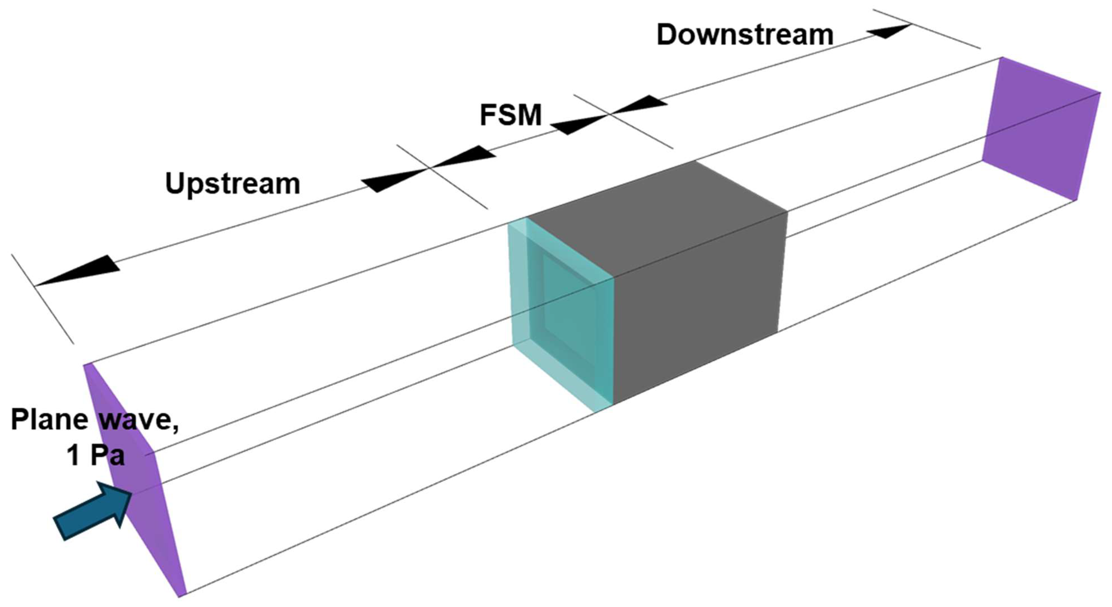
2.1. Finiete Element (FE) Analysis

Sound transmission loss values were calculated using the commercial finite element (FE) analysis program COMSOL Multiphysics 6.0. Three-dimensional Helmholtz and Navier equations were simultaneously solved to calculate the frequency domain’s acoustic pressure (p) and membrane displacement (d). We employed an Acoustic–Structure Interaction model, which couples acoustic pressure (acpr) and solid mechanics (solid), to conduct a comprehensive vibro-acoustic analysis of the FSM. This approach allowed us to account for both the mechanical properties of the fluid and the vibration of the membrane through acoustic pressure while also considering the stress and displacement of the structure via solid mechanics. Figure 1 illustrates the simulation conditions for calculating the sound transmission loss of the metamaterial unit cell. In this model, we considered the frame–membrane as a single integrated structure, allowing for a comprehensive analysis of their combined acoustic behavior. The model includes two acoustic waveguides, with non-reflecting boundary conditions applied at both ends to prevent reflections. A plane wave with an amplitude of 1 Pa was set to incident from the upstream side. The incident plane wave vibrates the unit cell, radiating reflected and transmitted waves upstream and downstream. To account for the vibroacoustic characteristics of the membrane, acoustic-boundary conditions were applied at the interface between air and the membrane. The interface between air and the frame was set as a rigid boundary condition, and the edges of the frame–membrane interface were constrained for fixation. The frame material was a soft urethane rubber commonly used as a molding material, with a 1040 kg/m3 density. Silicon rubber was used as the membrane material, with a density ρm = 1000 kg/m3, Young’s modulus Em = 9.5 MPa, and Poisson’s ratio νm = 0.48.

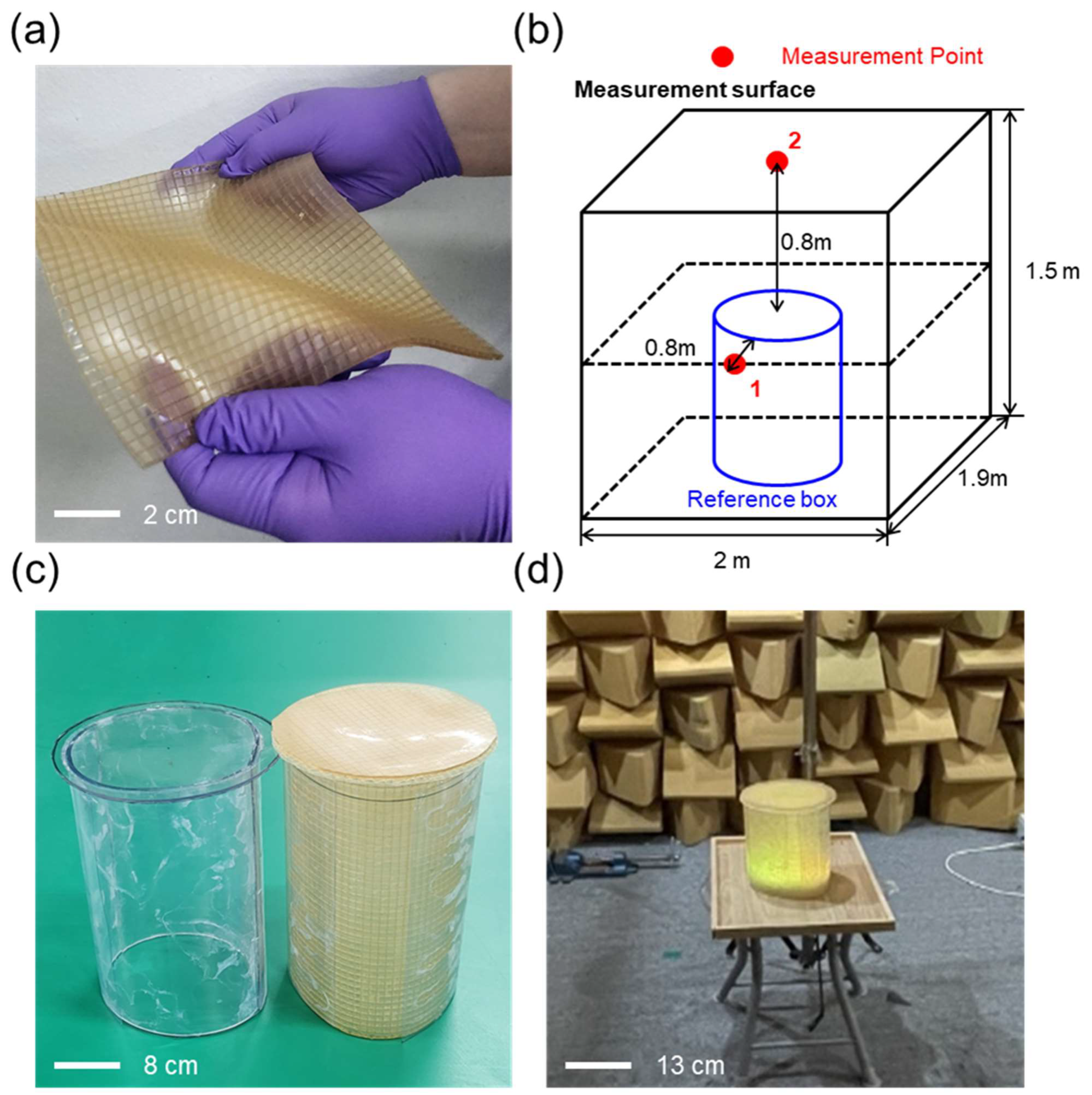
2.2. SPL Test for FSM

We fabricated FSM with the geometric parameters designed (Figure 2a) and conducted comprehensive acoustic testing with an open field test for enclosure-type soundproofing. Our acoustic measurement methodology, featuring a carefully curated sound source, employed a meticulously controlled environment. To ensure acoustic fidelity, we utilized a direct recording of vacuum cleaner noise transmitted via a Bluetooth speaker. This approach not only mitigated potential sound leakage associated with wired connections but also provided a known noise spectrum encompassing our target frequency range of 2000–5000 Hz. The experimental setup incorporated the FSM sample and strategically positioned microphones, enabling precise measurement of sound pressure levels both with and without the FSM. These measurements provided a direct comparison of the acoustic performance between the FSM and the control conditions.
As illustrated in Figure 2b–d, our test enclosure consisted of a reference box (0.2 m diameter, 0.5 m height). Sound waves were generated at one end, with the FSM blocking sides and opposite ends. This setup allowed us to measure the noise reduction achieved by the FSM across the frequency spectrum, focusing on our target range. We employed FSM-identical material for enclosure sealing to maintain acoustic integrity and minimize experimental error, ensuring optimal sound isolation. The experimental samples comprising the FSM and mass-law-based control group were precisely aligned perpendicular to the sound wave propagation direction. Microphones were strategically placed at points 1 and 2 to capture SPL measurements inside and outside the enclosure. The measured SPL represents structure-borne noise generated by the vibrating back plate of the FSM. These results indicate that the FSM blocks waves with high dynamic effective density and specific acoustic impedance. To ensure the accuracy and reproducibility of our results, we conducted multiple trials for each experimental configuration. The sound source was calibrated before each test session, and environmental factors such as temperature and humidity were carefully monitored and recorded. Additionally, we employed a high-precision laser vibrometer to measure the vibration characteristics of the FSM during acoustic excitation, providing valuable insights into its dynamic behavior.

3. Results

3.1. Structure of Flexible Soundproofing Metapanel

In this study, we designed the geometrical structure and dimensions of a Flexible Soundproofing Metapanel (FSM) for effective noise suppression in the target band (2000–5000 Hz), a range particularly significant for human auditory comfort. Figure 3a shows the geometrical structure of the FSM, consisting of a box-shaped frame and a vibrating membrane. The membrane is securely attached to the open face of the frame using an adhesive, creating a coupled system where membrane vibrations significantly influence the dynamic response of the radiating surface. However, at frequencies near the membrane’s resonance, a localized increase in acoustic transmission occurs due to the amplified motion of the membrane. Figure 3b illustrates the geometrical structure and dimensions of the FSM unit cell, indicated by a dotted cuboid. In this paper, we aimed to achieve high Sound Transmission Loss (STL) in the target frequency band by optimizing the geometric parameters Lx, Ly, Lz, tf, and tm so that each layer has different resonance frequencies.

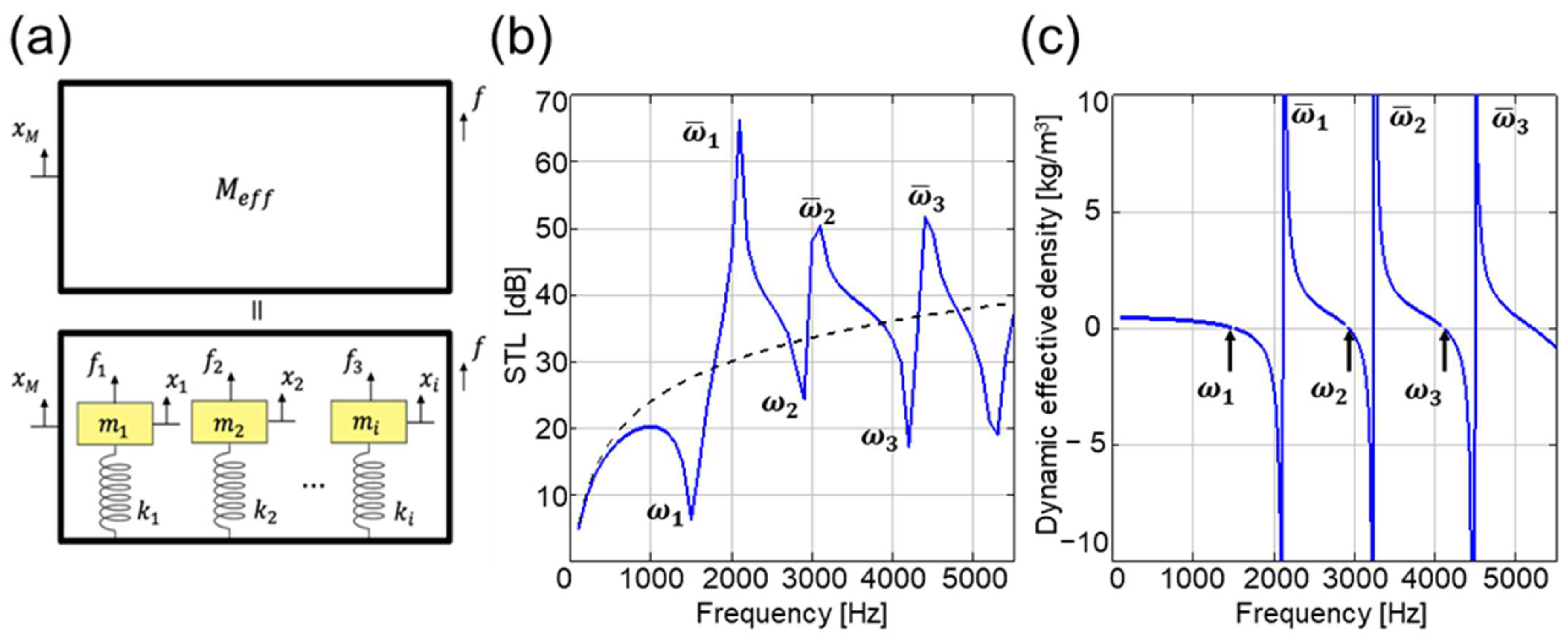
3.1.1. Sound Transmission Loss of FSM

We numerically calculated the STL of the FSM to determine the geometric parameters for achieving high STL in the target band. A two-step approach was used: (1) We found geometric parameters that position the frequency where the frequency-dependent effective mass density and bulk modulus of the FSM become zero between the target bands, allowing us to position the STL reduction outside the target band range. (2) We finally determined the mechanical properties satisfying the flexible FSM under the constraint that the STL in the target band should be higher than 20 dB (blocking more than 99% of incident wave energy).
The unit cell of the FSM can be analyzed as a spring–mass system consisting of a thin membrane attached to a frame, with the thin membrane having multiple natural frequencies of various modes. The dynamic effective mass of the unit cell is expressed by the following equation shown in Figure 4a.
M e f f = M + i = 1 n m i 1 ( ω / ω i ) 2 1 + i = 1 n α i 1 ( ω / ω i ) 2
In this equation, M represents the mass of the frame structure responsible for radiating acoustic energy. The term ω i ( = k i / m i ) denotes the eigenfrequency of the i-th spring–mass system, where mi and ki are the equivalent mass and stiffness of the i-th eigenmode, respectively. The parameter α i ( = f i / f ) is a coupling coefficient, indicating the ratio of the force acting on each equivalent mass to the force exerted on the frame. This formulation comprehensively represents the FSM’s dynamic behavior, accounting for multiple vibrational modes and their interactions with the frame structure.
Near the natural frequencies of the thin membrane, the system’s mass approaches zero. Subsequently, as the force and acceleration responses of the FSM become opposite, an anti-resonance region with negative dynamic mass is formed. This anti-resonance region is expected to have high soundproofing performance due to its characteristically high dynamic mass. These characteristics can be confirmed through the FSM’s STL. The equation for STL is as follows:
S T L = 10 log 10 s p i 2 d A s p t 2 d A
The STL graph shows a sharp decrease (dip) at the resonance frequency. Compared to the mass law, a considerably larger acoustic reduction rate is observed in the anti-resonance region.
Figure 4b illustrates the simulated STL of the FSM unit cell. For comparison, the STL of an equivalent unit cell calculated using the mass law is shown as a dashed line. The static area density of this equivalent unit cell is 1.9 kg/m2, identical to that of the soundproofing flexible FSM unit cell. The STL curve of the FSM unit cell (blue solid line) exhibits three peaks at 2100, 3100, and 4400 Hz, indicating high STL bands at these frequencies, which suggests that near-total reflection occurs at these frequencies due to the soundproofing flexible FSM unit cell. Conversely, three dips observed at 1500, 4200, and 5300 Hz show lower STL than conventional mass law, implying that more acoustic energy can pass through the soundproofing flexible FSM at these frequencies than through the equivalent cell. However, although these dips show relatively lower soundproofing performance than the equivalent mass law, they maintain STL values above 20 dB in most cases. These results indicate that the soundproofing flexible FSM demonstrates excellent soundproofing performance in specific frequency bands while maintaining effective noise-blocking capabilities across a wide range of frequencies.

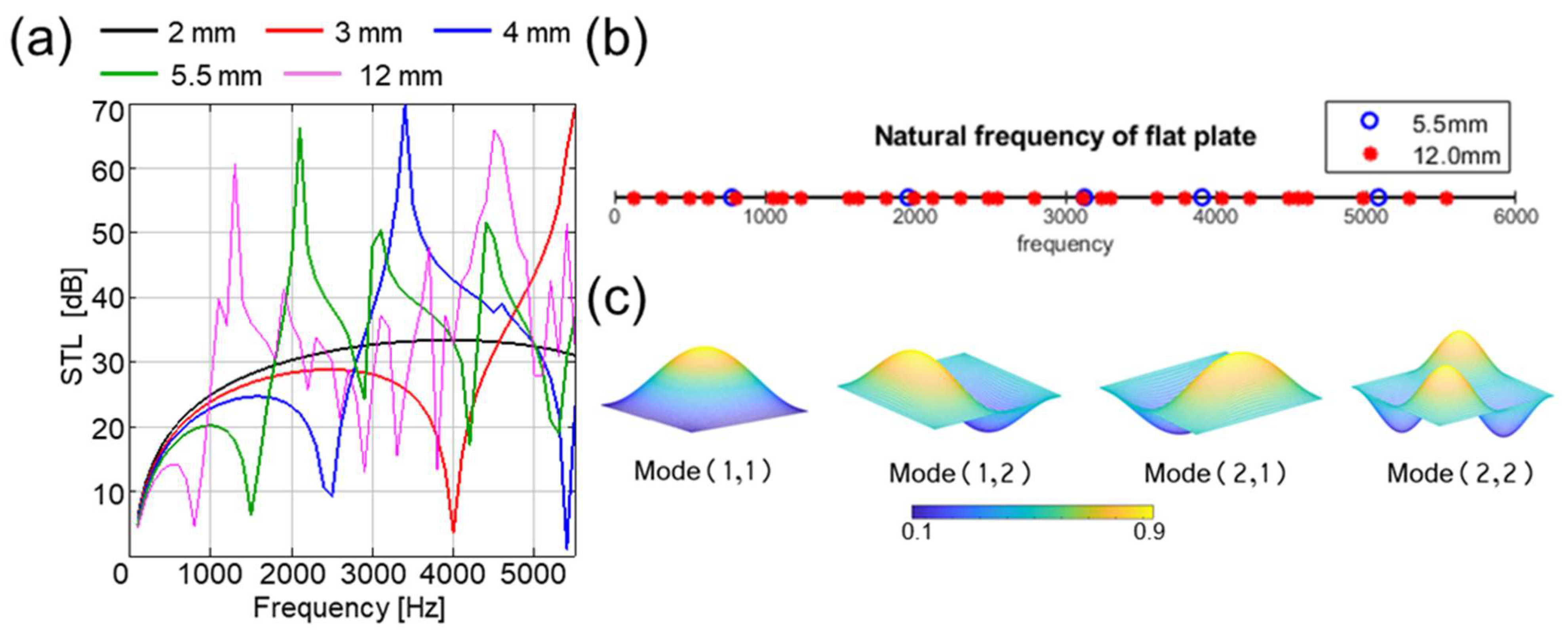
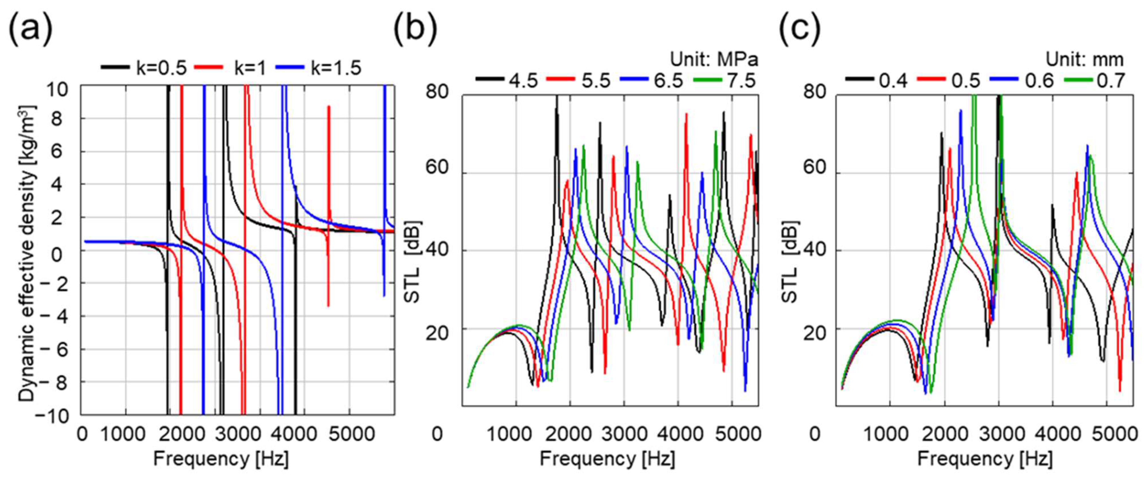
3.1.2. Design of Flexible Soundproofing Metapanel

Figure 5 provides a comparative analysis of the natural frequencies for unit cell size, offering insight into the dimensional effects on acoustic behavior. Figure 5a shows the STL values as a function of unit cell size. Figure 5b,c depict the 5.5 mm length unit cell exhibiting four distinct natural frequencies, while the 12 mm length unit cell displays numerous natural frequencies, demonstrating how these dimensions affect acoustic radiation characteristics.
Specifically, the STL curve for the 12 mm length unit cell shows a multitude of closely spaced dips across the frequency spectrum. This phenomenon can be attributed to the higher number of vibrational modes available in the larger unit cell, each contributing to a localized reduction in STL at its resonant frequency. In contrast, the 5.5 mm length unit cell, with its limited number of natural frequencies within the same range, produces a cleaner STL profile with fewer, more distinct dips.
These results illustrate that achieving efficient soundproofing performance in the desired band is challenging, highlighting the importance of selecting appropriate dimensions considering the properties of the thin membrane and frame. Therefore, in this study, we selected a unit cell size of 5.5 mm with fewer dips and a wide bandgap in the target frequency range.
In a spring–mass system, the unit cell’s resonance can be analyzed as vibrations induced by external forces acting on the thin membrane and the frame. The natural frequency of each mode is determined by its stiffness and area, causing the FSM’s STL to vary with material properties and dimensions. The following equation expresses a rectangular plate’s flexural rigidity (D), where E represents Young’s modulus, and ν denotes Poisson’s ratio. This relationship underscores the interconnectedness of material properties and geometric parameters in determining the acoustic performance of the FSM.
D = E h 3 12 ( 1 μ 2 )
Consequently, as the natural frequency of each membrane mode is determined by stiffness and area, the STL of the FSM varies with the material properties and dimensions.
Figure 6a illustrates the changes in STL due to variations in stiffness, a key factor affecting STL. As the material stiffness increases, the natural frequency values for each membrane mode increase, causing a rightward shift in both the dynamic effective mass and STL. This relationship implies that structures with high STL values in the desired frequency band can be designed through appropriate material selection. Understanding this relationship is crucial for optimizing the FSM’s performance across specific frequency ranges.
Rubber materials were chosen for this study to achieve flexibility while maintaining effective sound insulation properties. We compared and analyzed various rubber materials with different moduli, focusing on their acoustic properties and ability to create wide bandgap in the target frequency range. From four candidates (Young’s moduli: 4.5, 5.5, 6.5, and 7.5 MPa) that exhibited promising characteristics, urethane rubber (6.5 MPa) was selected as the optimal material for the FSM, as shown in Figure 6b.
We also analyzed the bandgap position shift in response to membrane thickness variations. As illustrated in Figure 6c, among the four membrane thicknesses examined (0.4, 0.5, 0.6, and 0.7 mm), the 0.6 mm thick membrane demonstrated the most suitable performance within the target frequency range. At this thickness, the bandgap aligns most closely with the target frequency band, and the STL value reaches its peak. Consequently, we selected 0.6 mm as the final membrane thickness.
Based on these findings, the final design parameters for the metamaterial panel’s unit cell are as follows:
  • Unit cell dimensions: Lx = Ly = 5.5 mm, Lz = 3.5 mm;
  • Frame thickness: tf = 0.5 mm;
  • Material: Urethane rubber with a Young’s modulus of 6.5 MPa;
  • Membrane thickness: tm = 0.6 mm.
This configuration optimizes the acoustic performance of the FSM within the desired frequency range while maintaining structural integrity and flexibility.
Figure 7 illustrates the vertical displacement of the unit cell when STL peaks occur in the anti-resonance region. Three primary modes ( ω ¯ 1 , ω ¯ 2 , ω ¯ 3 ) are observed in this figure, each exhibiting the following significant phenomena: (1) Membrane Vibration: The membrane vibrates in the opposite direction to the incident sound wave (acoustic force). (2) Anti-phase Superposition: The vibrations of the membrane and frame attain opposite phases and superpose. (3) Displacement Cancellation: Due to this anti-phase superposition, the total displacement of the entire unit cell approaches zero. (4) Formation of Anti-resonance Region: Anti-resonance occurs in this frequency region where total displacement is minimized, manifesting as peaks in the STL graph.
This mechanism significantly reduces the transmission of sound wave energy at anti-resonance frequencies, resulting in high acoustic insulation performance. These phenomena observed in each mode ( ω ¯ 1 , ω ¯ 2 , ω ¯ 3 ) are crucial factors enabling the metamaterial panel to achieve effective soundproofing performance across a wide frequency range. The interplay of these modes and their associated phenomena contributes to the FSM’s ability to attenuate sound effectively across various frequencies, making it a versatile solution for noise reduction applications. This multi-modal behavior is a key feature distinguishing metamaterial-based sound insulation from traditional mass-law-based approaches, offering superior performance in targeted frequency bands while maintaining overall broadband effectiveness.

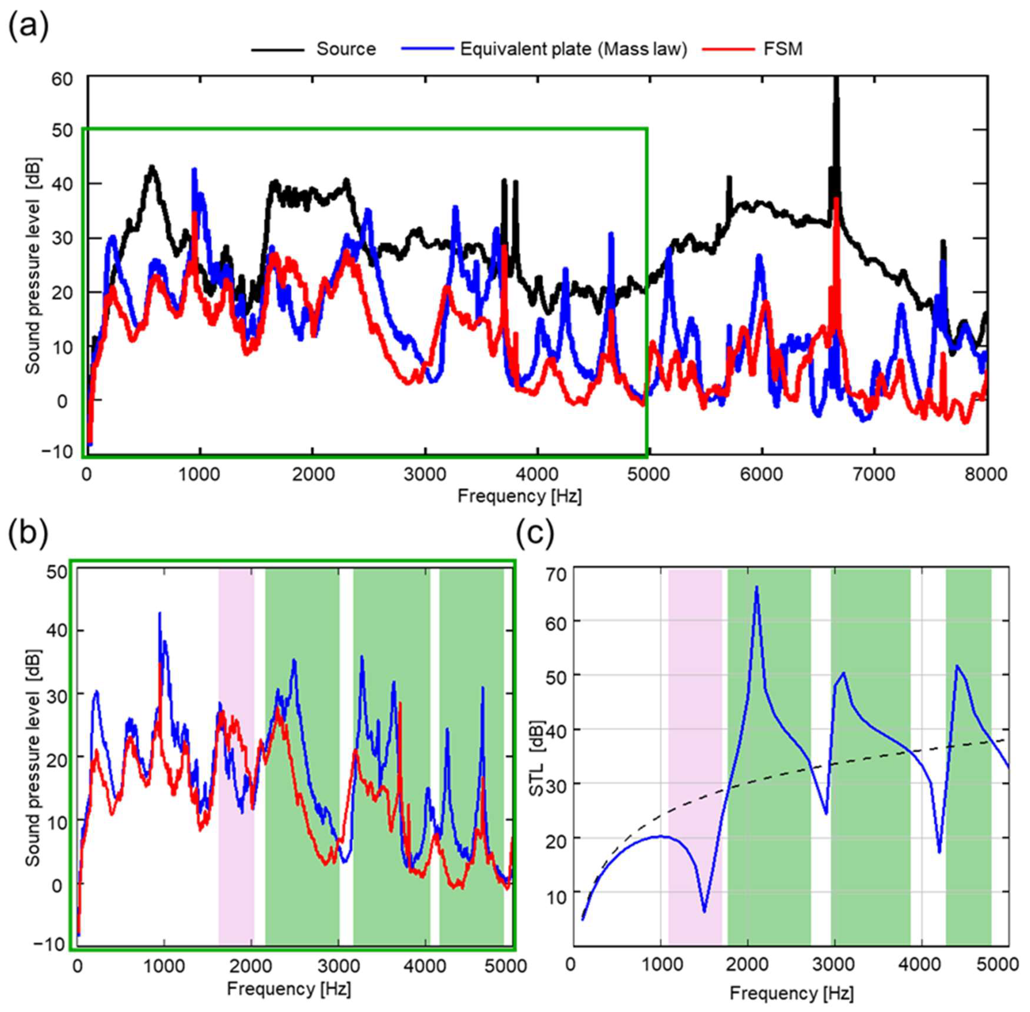
3.2. SPL Test for Enclosure-Type FSM

Figure 8a illustrates the Sound Pressure Level (SPL) measured in the 0–8000 Hz range for both the cylindrical FSM and a control group. The control group in this context represents an equivalent plate following the mass law, as shown in Figure 2c (left image), with a mass identical to that of the FSM. The equivalent plate data are included to demonstrate the superior sound insulation performance of the FSM compared to conventional materials of the same mass. The FSM exhibited superior soundproofing performance compared to the control group across most frequency bands, with notable results in specific high-frequency ranges. While the mass law suggests that STL typically increases with higher material density, our FSM demonstrated higher sound insulation performance than the control group, indicating that the FSM achieved high efficiency and low weight compared to traditional materials.
Figure 8b compares SPL between the FSM and the control group in the target frequency band. Our experimental SPL measurements confirm that the FSM achieves higher STL than predicted by the mass law, especially in the 2000–5000 Hz range. The FSM demonstrates excellent soundproofing performance, particularly in 2130–2990 Hz, 3210–4110 Hz, and 4130–4960 Hz.
Figure 8c presents the STL simulation data (Figure 4b) with specific regions highlighted. Green areas indicate where the FSM’s STL performance exceeds the calculated mass law, while red areas show where it falls below. This visual representation facilitates a direct comparison with the experimental SPL data in Figure 8b. It is important to note that STL and SPL have an inverse relationship: peaks in STL correspond to troughs in SPL, and vice versa. Comparing Figure 8b,c, we observe that the experimental results slightly shift towards higher frequencies relative to the simulation. However, both datasets consistently demonstrate high noise reduction effectiveness in the frequency ranges of approximately 2000–2800 Hz, 3100–3850 Hz, and 4150–4800 Hz. These ranges align with the green areas in Figure 8c and correspond to the low SPL regions in Figure 8b, validating our FEM model and confirming the FSM’s superior soundproofing capabilities, remarkably where it outperforms the mass law prediction.
Furthermore, we confirmed that the cylindrical FSM maintains flexibility while delivering excellent sound insulation. This combination of flexibility and performance highlights the FSM’s potential for various applications where effective soundproofing and adaptable form factors are required. These results suggest that our FSM design could be valuable in diverse noise-insulation scenarios, including but not limited to acoustic enclosures, automotive applications, and architectural acoustics. The flexibility and high performance demonstrated by the FSM open up new possibilities for noise control in various applications, particularly where adaptable form factors are required alongside effective soundproofing.

4. Conclusions

This study demonstrates that the Flexible Soundproofing Metapanel (FSM) offers significant advantages in lightweight design and flexibility while exhibiting excellent sound insulation performance, particularly in specific high-frequency ranges. Our experimental results confirm that the FSM can outperform conventional mass-law-based sound-absorbing materials, especially in high-frequency ranges.
We optimized the FSM using urethane rubber with Young’s modulus of 6.5 MPa and unit cell dimensions of Lx = Ly = 5.5 mm, Lz = 3.5 mm, tf = 0.5 mm, and tm = 0.6 mm. This configuration achieved superior sound insulation performance while maintaining lightweight and flexible characteristics.
The FSM’s flexibility allows its design and application to be tailored to fit the internal structures of products with various shapes and sizes, making it highly practical. This versatility, combined with its effective sound insulation properties, positions the FSM as a promising solution for noise control in diverse applications requiring soundproofing effectiveness and adaptable form factors.
Our findings present potential applications for FSM in various noise reduction fields, especially in industries such as small electronics, automotive, and aerospace, where weight reduction is crucial. The results open possibilities for achieving both lightweight design and efficient noise reduction simultaneously in product development, potentially improving overall product efficiency across various industrial sectors.
Future research could explore other materials with superior sound absorption properties or optimize unit cell dimensions to achieve even better performance. This approach could maximize noise reduction effects across a broader frequency range.
In conclusion, this research demonstrates the FSM’s superior performance over traditional mass-law-based materials. It highlights its potential to revolutionize noise control strategies across multiple industries, offering a balance of lightweight design, flexibility, and effective sound insulation.

Author Contributions

Conceptualization, D.J., S.K., J.K., H.K., S.L. and B.K.; methodology, D.J., S.K., J.K., H.K. and S.L.; software, D.J. and S.K.; validation, J.K., H.K. and S.L.; formal analysis, D.J., S.K., J.K., H.K., S.L. and B.K.; investigation, D.J., S.K., J.K., H.K., S.L. and B.K.; resources, B.K.; data curation, D.J. and S.K.; writing—original draft preparation, B.K.; writing—review and editing, B.K.; visualization, D.J., S.K., J.K., H.K. and S.L.; supervision, B.K.; project administration, B.K.; funding acquisition, B.K. All authors have read and agreed to the published version of the manuscript.

Funding

This work was supported by the Hongik University new faculty research support fund.

Institutional Review Board Statement

Not applicable.

Informed Consent Statement

Not applicable.

Data Availability Statement

The original contributions presented in the study are included in the article; further inquiries can be directed to the corresponding author.

Conflicts of Interest

The authors declare no conflicts of interest.

References

  1. Brekhovskikh, L. Waves in Layered Media; Elsevier: Amsterdam, The Netherlands, 2012; ISBN 978-0-323-16162-6. [Google Scholar]
  2. Yang, M.; Sheng, P. Sound Absorption Structures: From Porous Media to Acoustic Metamaterials. Annu. Rev. Mater. Res. 2017, 47, 83–114. [Google Scholar] [CrossRef]
  3. Bonnecaze, R.T.; Rodin, G.J.; Sigmund, O.; Søndergaard Jensen, J. Systematic Design of Phononic Band–Gap Materials and Structures by Topology Optimization. Philos. Trans. R. Soc. London. Ser. A Math. Phys. Eng. Sci. 2003, 361, 1001–1019. [Google Scholar] [CrossRef]
  4. Al Ba’ba’a, H.; Nouh, M.; Singh, T. Formation of Local Resonance Band Gaps in Finite Acoustic Metamaterials: A Closed-Form Transfer Function Model. J. Sound Vib. 2017, 410, 429–446. [Google Scholar] [CrossRef]
  5. D’Alessandro, L.; Belloni, E.; Ardito, R.; Braghin, F.; Corigliano, A. Mechanical Low-Frequency Filter via Modes Separation in 3D Periodic Structures. Appl. Phys. Lett. 2017, 111, 231902. [Google Scholar] [CrossRef]
  6. Wang, Q.; Li, J.; Zhang, Y.; Xue, Y.; Li, F. Bandgap Properties in Metamaterial Sandwich Plate with Periodically Embedded Plate-Type Resonators. Mech. Syst. Signal Process. 2021, 151, 107375. [Google Scholar] [CrossRef]
  7. Comi, C.; Driemeier, L. Wave Propagation in Cellular Locally Resonant Metamaterials. Lat. Am. J. Solids Struct. 2018, 15, e38. [Google Scholar] [CrossRef]
  8. Gao, N.; Zhang, Z.; Deng, J.; Guo, X.; Cheng, B.; Hou, H. Acoustic Metamaterials for Noise Reduction: A Review. Adv. Mater. Technol. 2022, 7, 2100698. [Google Scholar] [CrossRef]
  9. Liu, C.; Chen, L.; Lee, H.P.; Yang, Y.; Zhang, X. A Review of the Inerter and Inerter-Based Vibration Isolation: Theory, Devices, and Applications. J. Frankl. Inst. 2022, 359, 7677–7707. [Google Scholar] [CrossRef]
  10. Sheng, P.; Fang, X.; Dai, L.; Yu, D.; Wen, J. Synthetical Vibration Reduction of the Nonlinear Acoustic Metamaterial Honeycomb Sandwich Plate. Mech. Syst. Signal Process. 2023, 185, 109774. [Google Scholar] [CrossRef]
  11. Sugino, C.; Xia, Y.; Leadenham, S.; Ruzzene, M.; Erturk, A. A General Theory for Bandgap Estimation in Locally Resonant Metastructures. J. Sound Vib. 2017, 406, 104–123. [Google Scholar] [CrossRef]
  12. Lee, S.H.; Park, C.M.; Seo, Y.M.; Wang, Z.G.; Kim, C.K. Acoustic Metamaterial with Negative Density. Phys. Lett. A 2009, 373, 4464–4469. [Google Scholar] [CrossRef]
  13. Lee, S.H.; Wright, O.B. Origin of Negative Density and Modulus in Acoustic Metamaterials. Phys. Rev. B 2016, 93, 024302. [Google Scholar] [CrossRef]
  14. Yao, S.; Zhou, X.; Hu, G. Investigation of the Negative-Mass Behaviors Occurring below a Cut-off Frequency. New J. Phys. 2010, 12, 103025. [Google Scholar] [CrossRef]
  15. Wang, S.; Xiao, Y.; Guo, J.; Zhang, H.; Wen, J. Broadband Diffuse Field Sound Insulation of Double Layer Metamaterial Plates Lined with Porous Material. Appl. Phys. Lett. 2021, 119, 084103. [Google Scholar] [CrossRef]
  16. Ghaffarivardavagh, R.; Nikolajczyk, J.; Anderson, S.; Zhang, X. Ultra-Open Acoustic Metamaterial Silencer Based on Fano-like Interference. Phys. Rev. B 2019, 99, 024302. [Google Scholar] [CrossRef]
  17. Yu, X.; Lu, Z.; Liu, T.; Cheng, L.; Zhu, J.; Cui, F. Sound Transmission through a Periodic Acoustic Metamaterial Grating. J. Sound Vib. 2019, 449, 140–156. [Google Scholar] [CrossRef]
  18. Sun, M.; Fang, X.; Mao, D.; Wang, X.; Li, Y. Broadband Acoustic Ventilation Barriers. Phys. Rev. Appl. 2020, 13, 044028. Available online: https://journals.aps.org/prapplied/abstract/10.1103/PhysRevApplied.13.044028 (accessed on 26 August 2024). [CrossRef]
  19. Park, J.; Kwak, J.-H.; Song, K. Ultraslow Medium with an Acoustic Membrane-like Undamped Dynamic Vibration Absorber for Low-Frequency Isolation. Extrem. Mech. Lett. 2021, 43, 101203. [Google Scholar] [CrossRef]
  20. Jang, J.-Y.; Park, C.-S.; Song, K. Lightweight Soundproofing Membrane Acoustic Metamaterial for Broadband Sound Insulation. Mech. Syst. Signal Process. 2022, 178, 109270. [Google Scholar] [CrossRef]
  21. Li, Y.; Zhang, Y.; Xie, S. A Lightweight Multilayer Honeycomb Membrane-Type Acoustic Metamaterial. Appl. Acoust. 2020, 168, 107427. [Google Scholar] [CrossRef]
  22. Hu, G.; Tang, L.; Cui, X. On the Modelling of Membrane-Coupled Helmholtz Resonator and Its Application in Acoustic Metamaterial System. Mech. Syst. Signal Process. 2019, 132, 595–608. [Google Scholar] [CrossRef]
  23. Yang, Z.; Mei, J.; Yang, M.; Chan, N.H.; Sheng, P. Membrane-Type Acoustic Metamaterial with Negative Dynamic Mass. Phys. Rev. Lett. 2008, 101, 204301. [Google Scholar] [CrossRef] [PubMed]
  24. Yang, Z.; Dai, H.M.; Chan, N.H.; Ma, G.C.; Sheng, P. Acoustic Metamaterial Panels for Sound Attenuation in the 50–1000 Hz Regime. Appl. Phys. Lett. 2010, 96, 041906. [Google Scholar] [CrossRef]
  25. Mei, J.; Ma, G.; Yang, M.; Yang, Z.; Wen, W.; Sheng, P. Dark Acoustic Metamaterials as Super Absorbers for Low-Frequency Sound. Nat. Commun. 2012, 3, 756. [Google Scholar] [CrossRef] [PubMed]
  26. Kim, J.; Choi, E.; Jeon, W. Lightweight Soundproofing Meta-Panel for Separate Wide Frequency Bands. Mech. Syst. Signal Process. 2023, 184, 109647. [Google Scholar] [CrossRef]
  27. Malléjac, M.; Merkel, A.; Sánchez-Dehesa, J.; Christensen, J.; Tournat, V.; Groby, J.-P.; Romero-García, V. Zero-Phase Propagation in Realistic Plate-Type Acoustic Metamaterials. Appl. Phys. Lett. 2019, 115, 134101. [Google Scholar] [CrossRef]
  28. Beheshti, M.H.; Emkani, M.; Borhani Jebeli, M.; Tajpoor, A.; Firoozi Chahack, A.; Yarahmadi, G.; Piramoon, H.; Khoshehsahi, S.; Zobeidi, N. The Effect of Sound with Different Frequencies on Men and Women Noise Annoyance. J. Res. Health 2019, 9, 355–362. [Google Scholar] [CrossRef]
Figure 1. FE model used to simulate STL of the soundproofing MAM unit cell. Boundary probes can calculate the space-averaged pressure at a certain distance, similar to the microphones of the impedance tube.
Applsci 14 08833 g001
Figure 2. (a) Optical image of Flexible Soundproofing Metapanel (FSM). (b) Schematic diagram of the experimental setup for acoustic testing of the FSM. (c) Casted enclosure-type FSM (right) and control (left). (d) Experimental setup for the SPL test.
Applsci 14 08833 g002
Figure 3. (a) Schematic illustration of the FSM, showing the box-shaped frame and vibrating membrane. (b) Detailed dimensions and parameters of the FSM unit cell.
Applsci 14 08833 g003
Figure 4. (a) Concept diagram of the dynamic effective mass. A theoretical model of the FSM unit cell represented by equivalent spring–mass subsystems. (b) Calculated Sound Transmission Loss (STL) of the FSM unit cell compared to the mass law prediction (Dashed line: the calculated mass law. (c) Dynamic effective density of an FSM unit cell.
Applsci 14 08833 g004
Figure 5. Comparison of natural frequencies for different unit cell sizes: (a) STL values for various unit cell sizes, (b) natural frequencies for 5.5 mm unit cell and 12 mm unit cell, and (c) mode shape of the membrane of a unit cell.
Applsci 14 08833 g005
Figure 6. (a) Changes in STL due to variations in material stiffness. (b) STL curves for different rubber materials. (c) Effect of membrane thickness on STL and bandgap position.
Applsci 14 08833 g006
Figure 7. Vertical displacement of the FSM unit cell at anti-resonance frequencies, showing three primary modes ( ω ¯ 1 , ω ¯ 2 , ω ¯ 3 ).
Applsci 14 08833 g007
Figure 8. SPL test for enclosure-type FSM: (a) SPL graph comparing the cylinder-shaped FSM with the mass-law control group across 0–8000 Hz. (b) Comparison of SPL for the FSM in the target frequency band (2000–5000 Hz) (c) Simulated Sound Transmission Loss (STL) of the FSM unit cell compared to the mass law prediction (2000–5000 Hz). Green areas indicate where the FSM’s STL exceeds the mass law, while pink areas show where it falls below.
Applsci 14 08833 g008
Disclaimer/Publisher’s Note: The statements, opinions and data contained in all publications are solely those of the individual author(s) and contributor(s) and not of MDPI and/or the editor(s). MDPI and/or the editor(s) disclaim responsibility for any injury to people or property resulting from any ideas, methods, instructions or products referred to in the content.

