Abstract
In this work, the attenuation of surface seismic waves from large-scale phononic metamaterials is numerically studied. The proposed metamaterials consist of rectangular trenches that form either I-shaped or T-shaped cavities embedded at the ground surface. The numerical investigation includes the study of the response of the proposed structures for different values of their geometric parameters. In addition, modifications of the proposed structures where heavy cores coated with a soft material were considered in the cavities were also numerically studied. For a more realistic numerical approach, the transmission spectrum of a selected large-scale phononic metamaterial was also investigated in a suitable half-space numerical scheme. The results of the present research showed that the studied large-scale metastructures could be a very promising potential candidate for seismic shielding applications for the protection of existing urban or countryside structures. The proposed metamaterials are low in cost and easy to construct for the protection of existing buildings, critical infrastructures, or even entire urban areas without need for any kind of intervention at them, therefore providing an effective solution in the field of seismic isolation.
1. Introduction
The control of mechanical waves is timelessly among the most fundamental problems in nature, as it is well known that manipulating elastic or acoustic waves could open new perspectives and create new potential applications in plenty of technological fields [1]. Phononic crystals (PCs) are artificial composite structures that consist of a periodic arrangement of inclusions in a host material, often called the matrix material [2]. One of their fundamental properties is that their dispersion relation could be modified in several ways, according to the choice of the matrix material, the topology, and the dimensions of the inclusions, together with the shape and the material chosen for them [3]. They were introduced three decades ago as a solution to the problem of controlling elastic and acoustic waves [4]. The presence of areas in their band structure where no mechanical wave propagation is allowed, also known as phononic band gaps (PBGs) [2], gave rise to even more capabilities of those composites and expanded their possible applications. The study of PCs has attracted a lot of academic interest the last decades, and numerous technological applications have been proposed and implemented, such as acoustic waveguides, cavities, and filters [5,6,7]. In addition, the concept of PCs was also applied to acoustic isolation, acoustic cloaking, and for hypersound and heat control [8]. Acoustic metamaterials came up, providing new functionalities not found in PCs and influencing, apart from acoustic waves, the study of elastic waves. Their unique properties arise due to their locally resonant constituent units [9]. Especially in the last decade, due to the significant progress made in both computational science and manufacturing technology, mechanical metamaterials have faced widespread development and have been considered as potential candidates for a large number of technological solutions [10].
One of the most intriguing ideas that came up in the community is the transfer of the concept of PCs and acoustic metamaterials (AMs) to manipulate the propagation of seismic waves, and thus seismic metamaterials were raised as a new branch of elastic metamaterials [11,12]. Seismic waves are elastic waves that occur due to an earthquake event in the lithosphere of the Earth. They travel through the Earth, and when they reach its surface, they travel as surface waves, known as Rayleigh and Love waves [13]. Their dominant frequency ranges from a few tenths of to the area of some tens of . Thus, seismic waves belong to the lower edge of the phononic spectrum [8], and the challenge of controlling them to isolate a structure or even an urban area from an earthquake event is indeed noteworthy. In the literature, there have been proposed several ways of reclaiming structures inspired by PCs or AMs to manipulate seismic waves resulting in isolation of the base of a building or the area surrounding it [14]. Kelly described implementations of base isolation and an approximate linear theory of isolation that can be used for the design of base isolation systems that use multilayer elastomeric isolators [15]. Shi et al. proposed a new configuration of seismic isolation foundation containing several concrete layers and some rubber blocks, which are placed periodically to form a periodic foundation [16]. Aravantinos-Zafiris and Sigalas numerically examined structures that could be characterized as large-scale phononic metamaterials and have band gaps in the frequency spectrum of seismic waves when their dimensions are chosen appropriately [17]. Kim and Das studied a new device that could be considered an attenuator of a seismic wave that reduces the amplitude of the wave exponentially. The structure is designed to support conventional aseismic systems using AMs [18]. A simple and practical method of an earthquake-resistant design to support conventional aseismic designs using AMs to reduce the amplitude of a seismic wave exponentially was also studied by Torres-Silva and Cabezas [19]. Brun et al. presented a spectral approach, accompanied by an asymptotic model and numerical simulations for slender elastic systems such as long bridges or tall buildings [20]. Finocchio et al. introduced a seismic metamaterial composed by a chain of mass-in-mass systems that could be realized by a continuous structure within a 3D matrix of isochronous oscillators based on a sphere rolling over a cycloidal trajectory. This seismic metamaterial was able to filter the S-waves of an earthquake [21]. Miniaci et al. proposed a novel approach to the problem of seismic wave mitigation and discussed the feasibility of a passive isolation strategy for seismic waves based on large-scale mechanical metamaterials [22]. Brule et al. showed the experimental results of a seismic test carried out using seismic waves generated by a monochromatic vibrocompaction mode [23]. Recently, Colombi et al. realized a geophysical experiment that demonstrates that a Rayleigh wave, propagating in soft sedimentary soil at frequencies lower than 150 Hz, experiences strong attenuation when interacting with a forest [24]. In the field of seismic metamaterials, Krödel et al. studied numerically and experimentally the use of metastructures to shield sensitive buildings from waves generated by an earthquake [25]. Seismic metamaterials embedded at the ground surface of granular media were also studied by using small-scale physical models with laser measurement techniques [26,27]. Moreover, artificial landforms such as terraced slopes were recently studied as potential seismic metasurfaces for the attenuation of seismic waves [28,29].
Recently, several studies have been conducted, which include a plethora of proposed seismic metamaterials of several shapes that are either considered embedded in the ground surface or stand at the ground surface as pillars. Wang et al. proposed a seismic metamaterial that consisted of curved boundaries on a square cross-section that resulted in the reduction in the contact area between adjacent cells and achieved a wide band gap at a very low frequency range [30]. Guo and Chen studied numerically vertical resonators, which are composed of a periodic array of square structures that are buried vertically along the depth and can attenuate Love waves [31]. Similar seismic metamaterials of rectangular geometries that implement the negative Poisson’s ratio of the auxetic foam have also been numerically investigated for their effectiveness on the attenuation of surface seismic waves [32,33]. V-shaped and N-shaped pillars were studied for their performance as seismic metamaterials by Su and Wang and provided wide band gaps for surface waves [34]. Xu et al. studied wide band gaps in seismic metamaterials, which were composed of H-shaped steel columns covered with rubber [35]. Zeng et al. numerically studied the use of I-shaped pillars as seismic metamaterials that provided low frequency band gaps [36]. Inverted T-shaped pillars were also studied by Zeng et al., both numerically and experimentally, as seismic metamaterials with wide frequency band gaps in the low frequency range [37]. Li et al. proposed a radial periodic arrangement of steel rings of rectangular, I-shaped, and T-shaped cross-sections that were embedded in soil for the attenuation of Lamb and surface seismic waves [38]. As PCs and AMs are a constantly evolving scientific area, new ideas that are now being implemented for sound waves [39] in combination with machine learning techniques [40] could provide the community with novel and more effective structures suitable for seismic isolation applications.
It is evident from the relevant research progress that the manipulation of the propagation of seismic waves with seismic metamaterials triggered the academic interest. It is also important to mention that each proposed seismic metamaterial provides specific limitations to its potential applicable field, which is related to several parameters such as its geometry, the combination of used materials, and its geometric dimensions [11]. For example, seismic metamaterials, which are designed for the foundations of a structure [15,16,17], although they could be very effective, can only be implemented in new structures and not in existing ones. Therefore, for the implementation of seismic metamaterials for protecting existing infrastructures, several shapes, geometries, and proposed strategies were studied and are more likely to be implemented in the field. Some of them are considered embedded in the ground surface [22,23,25,30,31,32,33,35,38], whereas another strategy of implementation is placing the structures to stand at the ground surface as pillars [34,36,37]. It should be noticed at this point that seismic metamaterials that stand at the ground surface as pillars and provide band gaps either based on local resonances or the Bragg scattering, despite their effectiveness on wave attenuation, could have stability issues caused by the strong ground motion of a surface seismic wave. In addition, their formation demands available space in front of or around the infrastructure, which is aimed to be protected. This could limit the free available space around an infrastructure. On the contrary, seismic metamaterials that are embedded into the ground surface, like the ones studied in this work, could be considered more practical and less space-consuming, apart from their effectiveness and applicability for the protection of several kinds of infrastructure.
In this work, I-shaped and T-shaped trenches, which are considered embedded in the ground surface, are studied numerically as large-scale phononic metamaterials (LSPMs) for the isolation of surface seismic waves. The dispersion relation of each examined structure is studied by using the finite element method and the Bloch theorem, and the calculated limits of the PBGs of each examined structure were recorded. In addition, for the investigation of the optimal performance of each examined structure, an optimization strategy was followed by studying the effectiveness of each geometric parameter on the PBG width. Moreover, for a more realistic approach to their efficiency, the transmission spectrum of selected structures was also calculated by using a proper numerical half-space scheme.
2. Materials and Methods
The proposed structures consist of rectangular trenches in the ground surface that form I-shaped or T-shaped cavities. Figure 1 shows the unit cell of each structure together with its geometric parameters. Each cubic unit cell has edge , which is the lattice constant of the structure. Figure 1a shows the I-shaped LSPM, and Figure 1b shows a top view of it with all relevant geometric parameters. The length of each I-shaped trench is symbolized as , and its width is . The case where the I-shaped trench is filled with a coated heavy core is shown in Figure 1c. The rubber coating has thickness d. The relevant T-shaped LSPM is shown in Figure 1d,e. The horizontal part of the T-shaped structure has geometric parameters, which are symbolized as and for its length and width, respectively. The case where a heavy T-shaped core is filling the cavity is shown in Figure 1f. The width of the rubber coating is d. For better understanding of the materials used, the inset with the representation of each color is also included in Figure 1.
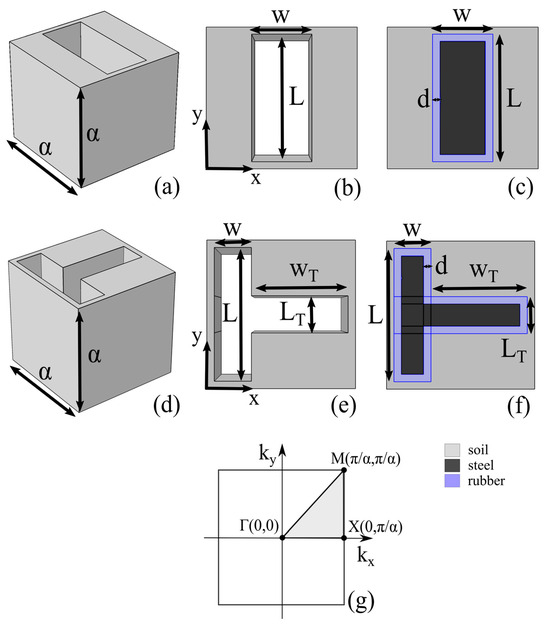
Figure 1.
Schematic representations of the unit cell for each examined structure: (a) The unit cell of the I-shaped LSPM, and (b) a top view of this unit cell. (c) A top view of the I-shaped trench, which is filled with a coated steel core. (d) The unit cell of the T-shaped LSPM, and (e) a top view of this unit cell. (f) A top view of the T-shaped trench, which is filled with a coated steel core. (g) The first Brillouin zone where the high-symmetry examined directions, , are noted.
For the calculation of the band structure of each proposed geometry, the Bloch theorem together with the finite element method, which is included in the commercial software package COMSOL(5.5) Multiphysics, were used. Bloch–Floquet periodic boundary conditions were considered at the vertical sides of each unit cell, whereas free boundary conditions were used at the top and bottom sides of each unit cell. Thus, the real eigenvalues of each structure were calculated along the high-symmetry directions, , of the first Brillouin zone, as shown in Figure 1g. The calculated real eigenvalues together with the relevant values of the eigenvector constitute the dispersion relation for each structure, which is represented in the band structure. The values of the calculated real eigenvalues with the relevant values of the eigenvector are represented with black asterisks in the band structure diagrams which will be presented in the following sections. The discretization of the geometry, which was used for the calculations of the band structures, consisted of a customized four-node free tetrahedral standard mesh with a minimum element size of 0.1 m, a maximum element size of 1 m, and a maximum element growth rate of 1.45. This choice led to good convergency, providing an error estimate of less than , as shown in the relevant convergence plots during the solution process, and thus provided accurate results, up to the maximum studied frequency in this study, which was 6 Hz.
For a more realistic numerical approach to the effectiveness of the proposed structures, the transmission spectrum was calculated for the one that provided a better solution for surface wave attenuation. The calculation of the transmission was performed in a suitable three-dimensional half-space numerical domain, as shown in Figure 2. The size of the computational half-space was 50α along the x direction and 25α along the z direction. The thickness of the computational domain along the y direction was equal to the lattice constant . At the vertical sides and the bottom of the half-space, perfectly matched layers (PMLs) were considered to avoid reflections from the boundaries. The PML layer in the half-space was selected at 5α to be comparable to half of the largest wavelength in the simulation. This choice eliminated the reflections from the boundaries as will be presented in the relevant mode shapes from the middle cross-section of the numerical three-dimensional half-space and provided reliable results with good agreement when compared to the relevant calculations for the band structure. At the top of the half-space free boundaries were adopted to mimic the real ground surface during the wave propagation. Continuity periodic boundary conditions were considered along the y direction. The top view of the numerical half-space is presented in Figure 2b. The excitation (E) was considered as a vertical prescribed displacement on a line segment equal to the lattice constant at the left side of the surface of the half-space, whereas the LSPM was considered at the other side of the surface. The excitation at the surface of the half-space is expected to generate both surface and bulk waves, and therefore the examined LSPM was at such a distance from the source that the bulk waves could be considered negligible. Six repetitive unit cells constitute the examined LSPM, as shown in Figure 2b. For better understanding of the presented numerical scheme, Figure 2c shows, as an example, the unit cell of the I-shaped LSPM that was considered for this analysis. The numerical data of the components of the displacement field were collected at the detection point, which is symbolized as D.
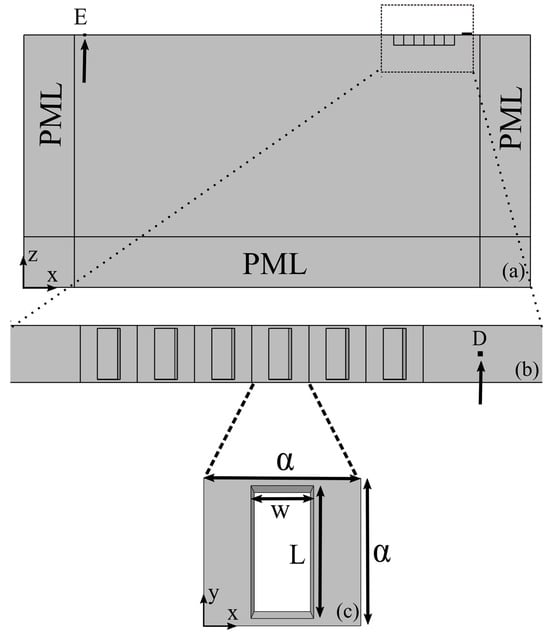
Figure 2.
(a) A side profile of the numerical domain of the three-dimensional half-space, which was used for the calculation of the transmission spectrum. (b) A top view of the numerical domain. (c) A selected top view of the unit cell of the I-shaped LSPM for the transmission calculation.
The transmission spectrum of the structure was calculated from the numerical data collected at the detection point D of the half-space, normalized to the relevant data at the same point of the half-space without the presence of the LSPM. The vertical component of the displacement field was considered for the calculation of the transmission spectrum, as it is well known that the vertical component of the surface wave causes most of the damage in a building. In more detail, the collected data in the frequency domain at point D of the vertical component of the displacement field, , under the presence of the LSPM, were divided by the relevant data at point D, , for the flat ground surface (GS), without the presence of the LSPM in the numerical domain. The transmission coefficient was calculated from the ratio at each examined frequency. A second detection point was also considered next to point D, at a distance α/2, to ensure the validity of the calculations. The results from both detection points were almost the same, and therefore only the results from point D are presented. For the meshing of the structure according to the available computational resources, a maximum element mesh size of 2.5 m was used. This choice provided satisfactory results for the examined frequency range, which enlightened the effectiveness and potential of the studied structure, as will be analyzed in the following sections of the manuscript.
The materials used in the calculations were commonly employed for such structures, as documented by the relevant literature; such materials are considered linear, homogeneous, and isotropic. A sandy type of soil was considered, which has Young’s modulus , Poisson ratio , and density . For the cases where a steel core is considered, the relevant parameters for steel were Young’s modulus , Poisson ratio , and density , and for the rubber coating, the parameters for rubber were Young’s modulus , Poisson ratio , and density . The chosen materials for the trenches filled with a coated core are materials that are used in several kinds of construction. Steel is a material that is used very often in almost all kinds of buildings and other critical infrastructures, such as bridges, as it is known for its long-term durability. Furthermore, rubber is also known for its uses as a vibration absorber and has also been used a lot in the literature as a constitutive material and in real constructions. Sandy-type soil was selected as a well-known type of soil that can represent many realistic scenarios of places where a possible application of the studied metamaterials could also be applied. It should be noted at this point that a selection of a different type of soil, which would represent another type of ground material, is expected to affect only the PBGs’ limits in a way similar to the wave velocity values of the selected type of soil. If, for example, a rock type soil is selected for which the wave velocities are higher than the selected sandy type of soil, then the PBGs would be expected to have higher frequencies than the ones calculated for the sandy type. This fact, though, cannot overturn the observations of this work regarding the performance of the studied LSPMs. Furthermore, by assuming that the parameters of the materials are independent of frequency, the presented analysis, where the lattice constant was considered , can be scaled to any other value of , thus providing a compact and representative content of the present study to other possible applications in addition to seismic isolation. As it is well known from the theory of PCs, the resulting limits of the band gaps of a phononic structure are related to the chosen dimension of the lattice constant and are shifted according to a modification of the later. If, for example, the lattice constant α is multiplied by a factor of two, then the limits of the calculated band gaps will be divided by the same factor. The scalability of the proposed LSPM makes them potential candidates for several uses beyond seismic isolation, such as vibrations from a railway, where a selection of a smaller lattice constant would tune the band gaps to higher frequencies suitable for surface wave attenuation caused by a railway.
3. Results
3.1. I-Shaped LSPMs
The first structure that was examined was the rectangular trench that forms an I-shaped LSPM. Preliminary numerical calculations showed that the structure becomes more effective when the length of the trench increases, and therefore the varying parameter for the optimization strategy of this LSPM was its width , while the length was selected as . The calculations showed that this structure has wide PBGs for all examined cases at a very low frequency range, although these gaps are found only along the ΓΧ direction. The numerical results for the examined cases are collected in Table 1, where the calculated lowest ( and highest ( frequency limits of each PBG are listed. The gap over mid-gap ratio , where and , was also calculated and listed in Table 1 as a measure of the width of each calculated gap. For the case where , two PBGs were calculated. The first between 1.90 and 3.26 Hz with , and the second between 3.97 and 4.41 Hz with . When , the two calculated PBGs were between 1.74 and 3.21 Hz with and between 3.32 and 4.15 Hz with . The last examined case for this structure was for width , and the two calculated PBGs were between 1.68 and 3.10 Hz with and between 3.26 and 3.74 Hz with . As the width of the trench increases, the limits of the PBGs are calculated in lower frequencies without significant change in the PBG width. For the case where , the band structure with the relevant mode shapes of the displacement field for the lowest and highest frequency of the first PBG is shown in Figure 3.

Table 1.
Collected results for the case of I-shaped LSPMs and the relevant with the coated steel core.
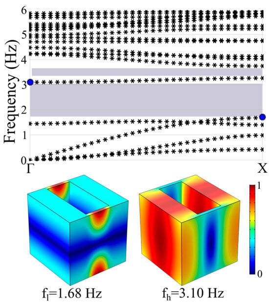
Figure 3.
The band structure of the I-shaped LSPM for the case where (top) and the relevant mode shapes of the normalized displacement field for the lowest ( and highest ( frequencies of the first PBG (bottom), which are indicated with the blue asterisks in the band structure.
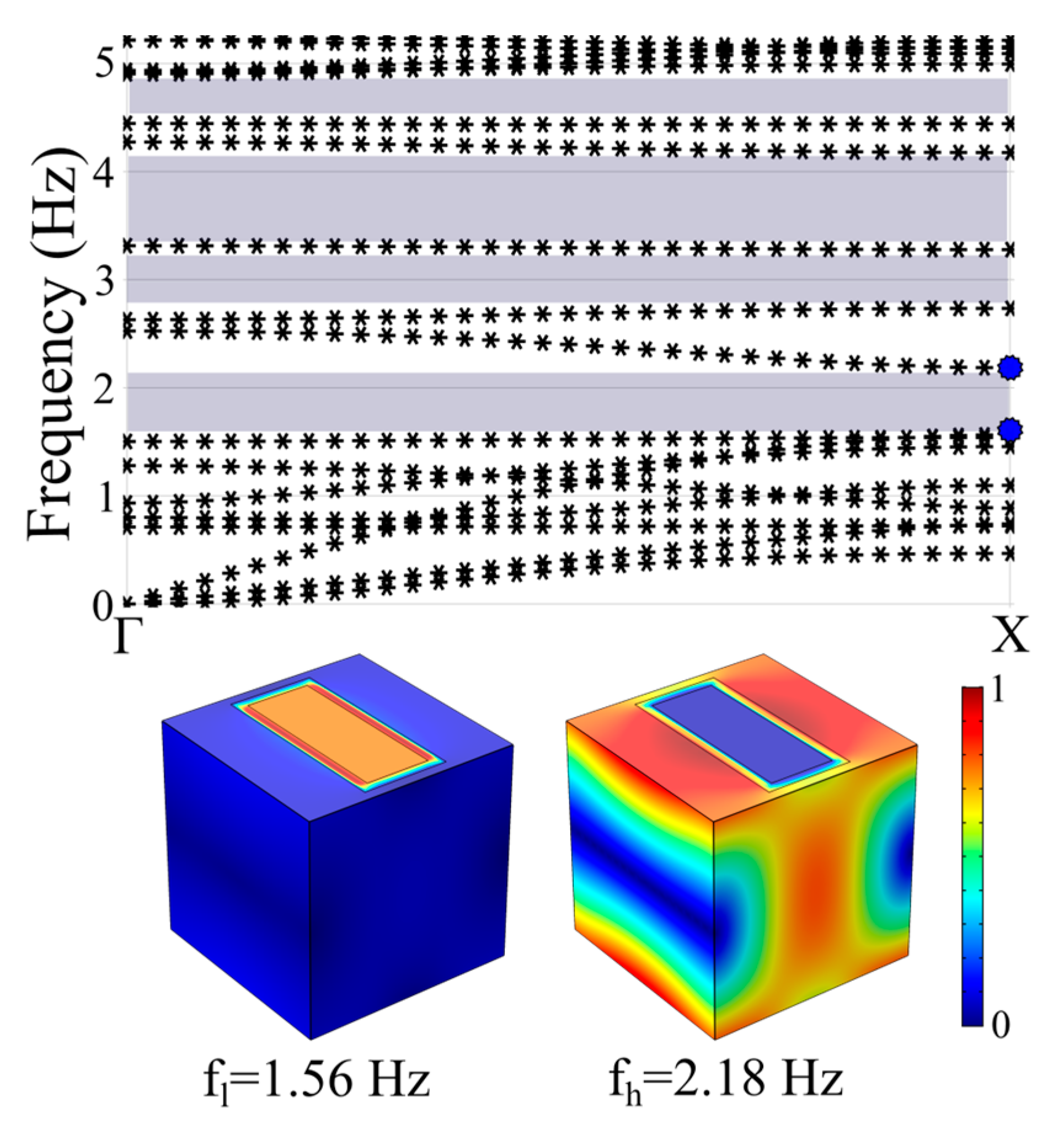
The I-shaped cavities, which are filled with a coated steel core, are also shown in Table 1 and provide significant interest regarding the effectiveness of the structure. The rubber coating had thickness . Although the calculated PBGs are found again only along the ΓΧ direction and are generally not as wide as the empty I-shaped trench, the case where showed four PBGs below the frequency of 5 Hz. The first is between 1.56 and 2.18 Hz with , the second is between 2.73 and 3.28 Hz with , and the third is between 3.31 and 4.17 Hz with . There was also a smaller gap between 4.44 and 4.90 Hz with . The band structure together with the mode shapes for the lowest ( and highest ( frequencies of the first PBG are shown in Figure 4.

Figure 4.
The band structure of the I-shaped LSPM with a coated steel core for the case where (top) and the relevant mode shapes of the normalized displacement field for the lowest ( and highest ( frequencies of the first PBG (bottom), which are indicated with the blue asterisks in the band structure.
3.2. T-Shaped LSPMs
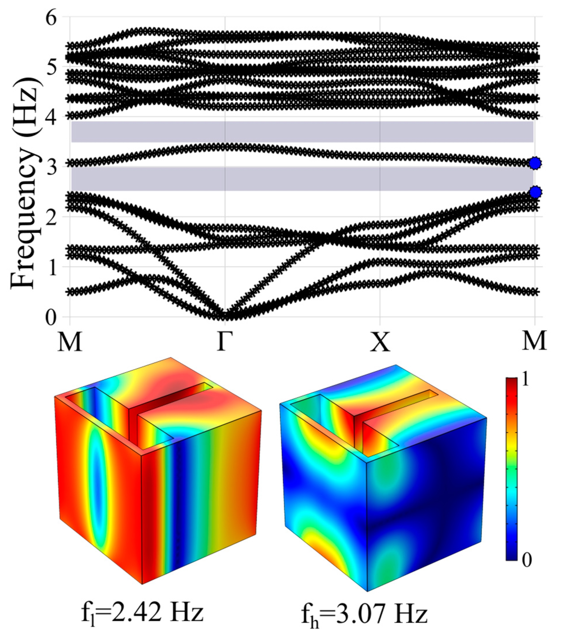
The T-shaped LSPM was also examined, and the results for this set of calculations are collected in Table 2. Aravantinos-Zafiris and Sigalas [17] showed numerically that an abrupt reduction in the cross-section of a column, and therefore a T-shaped formation, could create wide band gaps. Following the same architecture model, the T-shaped trench was considered an LSPM. The results showed wide and complete PBGs, i.e., along all examined high-symmetry directions, , of the first Brillouin zone, although not as wide as for the I-shaped LSPM. The varying parameter for this set of calculations was the length , and the rest parameters were , , and . For , the two calculated PBGs were between 2.42 and 3.07 Hz and between 3.39 and 4.02 Hz, with calculated at 0.24 and 0.17, respectively. For , there were also two calculated PBGs between 2.50 and 3.06 Hz and between 3.35 and 3.94 Hz, with calculated at 0.20 and 0.16, respectively. The last examined case was for , where only one PBG was found between 2.63 and 2.97 Hz with . The band structure of the case where , with the relevant mode shapes of the limits of the first band gap, is shown in Figure 5. It is important to note at this point that apart from the complete PBGs that were calculated, there are also even wider PBGs along the ΓΧ direction. For the case presented in Figure 5, the PBGs along the ΓΧ direction are between 1.84 and 3.20 Hz with , and between 3.39 and 4.20 Hz with .
Table 2.
Collected results for the case of T-shaped LSPMs and the relevant with the coated steel core.

Figure 5.
The band structure of the T-shaped LSPM for the case where (top) and the relevant mode shapes of the normalized displacement field for the lowest ( and highest ( frequencies of the first PBG (bottom), which are indicated with the blue asterisks in the band structure.
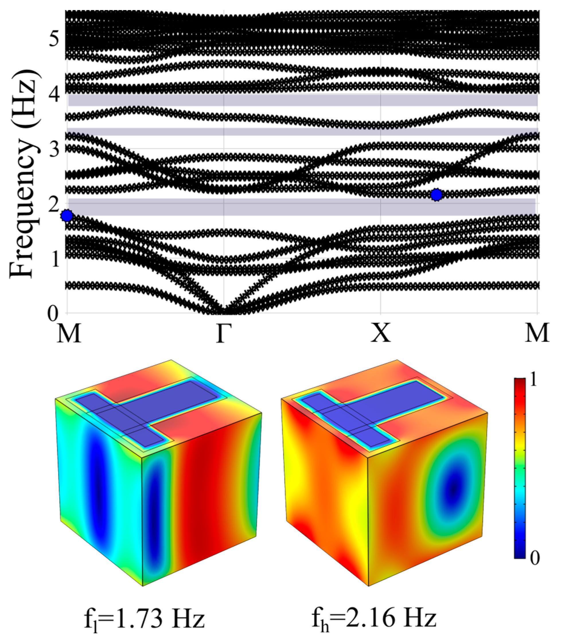
The case where the T-shaped trench is filled with a coated steel core, where the rubber coating had thickness , although provided complete PBGs, did not significantly improve the performance of the structure. The most interesting case was for . For this case, a PBG was calculated between 1.73 and 2.16 Hz with a PBG width of 0.22. There were also two smaller gaps between 3.23 and 3.42 Hz and between 3.71 and 4.07 Hz with widths of 0.06 and 0.09, respectively. The band structure for this case is presented in Figure 6. In the same figure, the normalized displacement field for the band gap edges is also shown. For , a small PBG was calculated between 3.09 and 3.46 Hz with and two other small gaps only along the ΓΧ direction between 1.64 and 2.11 Hz and between 3.57 and 4.24 Hz.
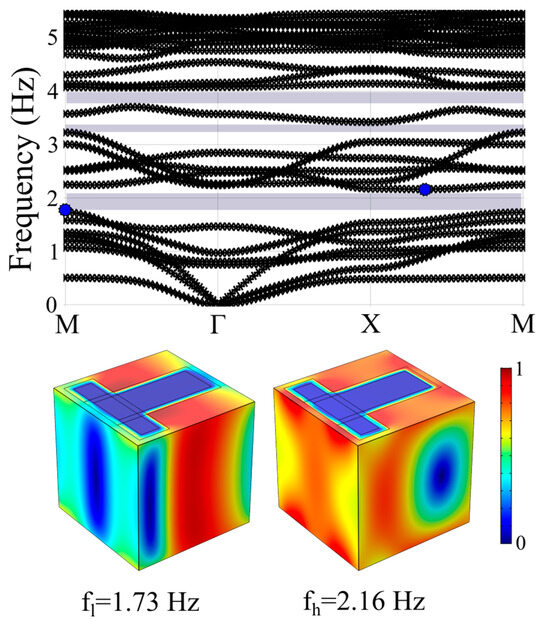
Figure 6.
The band structure of the T-shaped LSPM with coated steel core for the case where (top) and the relevant mode shapes of the normalized displacement field for the lowest ( and highest ( frequencies of the first PBG (bottom), which are indicated with the blue asterisks in the band structure.
3.3. Transmission Calculations
The calculation of the transmission spectrum was followed to have a complete numerical approach and to validate the results from the band structure calculations. Due to its high computational cost, there has been a selection from the studied structures to check for its seismic isolation effectiveness in combination with the relevant flat surface. From the presented results of the band structures, the I-shaped LSPM, where and , was the choice for this part. For this case, the two calculated PBGs were found within the lowest frequencies, between 1.68 and 3.10 Hz and between 3.26 and 3.74 Hz, and the first gap had the highest calculated width . The calculated transmission spectrum for this case is shown in Figure 7a. The results are in very good agreement with the corresponding results for the band structure of Figure 3. A slight shift to higher frequencies must be attributed to the different mesh size that was selected for the calculation of the transmission as explained in the “Methods” section and the presence of the soil substrate of the half-space. For example, there is a pass band in the calculated band structure of the examined I-shaped LSPM between 3.10 and 3.26 Hz, as indicated from the limits between the first and second PBGs. The transmission calculation showed this passing zone within a frequency range between 3.6 and 3.8 Hz, as indicated in Figure 7a. Overall, the calculation of the transmission spectrum validated the band structure calculations, indicating the effectiveness of the proposed structure for surface wave attenuation.
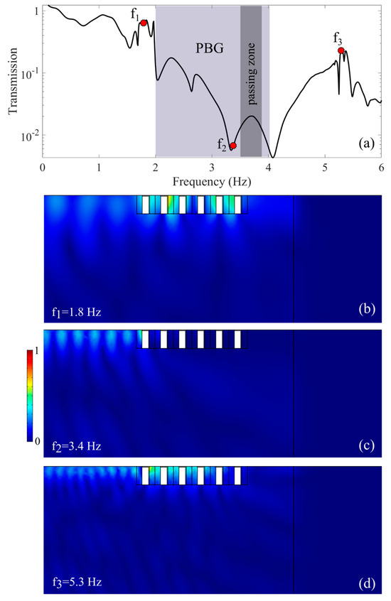
Figure 7.
(a) The transmission relation for the I-shaped LSPM where and . (b–d) Mode shapes of the absolute value of the vertical component of the displacement field, normalized to its maximum value, for frequencies (b) , (c) , and (d) .
For a better understanding of the attenuation mechanism, three mode shapes are shown in Figure 7 that represent the absolute value of the vertical component of the displacement field, normalized to its maximum value. The selection of the mode shapes was from the middle cross-section of the numerical three-dimensional half-space that was used in the simulations and are focused on the right part where the LSPM is designed. The mode shapes of Figure 7b,d clearly show that for the selected frequencies and , there are modes passing the LSPM, whereas for the selected frequency , the vertical component of the displacement field, shown in Figure 7c, is nearly zero at the surface after the LSPM, indicating its attenuation performance.
4. Discussion and Conclusions
The protection of critical infrastructure against a seismic event or ground vibrations that could be created from manmade sources, such as a railway or an industrial unit, is mandatory, and the scientific and technological community are seeking effective ways for achieving this goal. At the present contribution, the artificial structures that were studied numerically were based on the well-known concepts of PCs and AMs. This study included a first set of calculations of the band structure for each studied geometry. The results for the I-shaped LSPMs showed PBGs only along the ΓΧ direction, whereas the relevant calculations for the T-shaped LSPMs provided complete PBGs along all directions of the first Brillouin zone. After a numerical research for the optimum parameters, the I-shaped geometry provided an optimal performance for length and , whereas the best performance for the T-shaped geometry was achieved by minimizing the horizontal part of the T-shape and therefore for , , , and for . For all the examined cases, the lattice constant was kept at . The filling of each structure with a rubber-coated steel core reduced the lower limits of the PBGs for specific cases, although this reduction was not significant and the widths of the PBGs were smaller compared to those of the empty trenches, either of I-shape or T-shape.
It is evident according to the results of the calculations that one major advantage of the T-shaped LSPMs is that they provide complete PBGs along all directions of the first Brillouin zone in contrast to the I-shaped LSPMs, for which the PBGs are only along the ΓΧ direction. Furthermore, for both examined geometries, the empty trenches should be considered a preferable solution compared to the relevant with a rubber-coated steel core. Apart from the smaller PBGs provided by the latter, the empty trenches are much simpler in construction and, consequently, should be much more cost-effective. It should also be mentioned at this point that the gaps for both cases of the empty trenches could be further tailored by choosing a higher lattice constant, which will result in even lower limits of the PBGs. Another issue that arises from the numerical results concerning the case of the empty trenches, T-shaped or I-shaped, is which one should be preferable according to the results. As already mentioned, T-shaped LSPMs provide complete PBGs, whereas the PBGs of the I-shaped LSPMs are only along the ΓΧ direction. On the other hand, the I-shaped LSPMs seem to be more effective as they provided the best studied performance. As already commented, for this case, the two calculated PBGs along the ΓΧ direction were found within the lowest frequencies, between 1.68 and 3.10 Hz and between 3.26 and 3.74 Hz, and the first gap had the highest calculated width
. The fact that this structure does not provide complete PBGs but only along
the ΓΧ direction could be technically overcome by placing a sequent of the relevant I-shaped trenches on the periphery of a structure to be protected and thus achieving protection from all possible directions of the incoming surface wave. Alternatively, I-shaped trenches could be an ideal solution for cases where the placement of the vibration source is known, such as a railway or, for the case of seismic waves, a known and well-established seismic fault.
The calculations of the band structures were followed by a set of higher computational cost simulations in a more realistic scheme to have a more holistic approach to the studied geometries. The transmission spectrum was calculated for the I-shaped LSPM, which provided the most promising attenuation characteristics as explained in the previous section. The results, although expected to exhibit some differences with the corresponding ones of the band structure, nevertheless are in very good agreement with the latter, validating thus the predictions based on the calculations of the dispersion relations. Therefore, the extracted conclusions from the dispersion relations for all the examined geometries are safe and indicate that each of the proposed geometries could be a potential candidate for applications in seismic isolation. It should also be noted that a reduction in the lattice constant of the structure ten times would cause a shift in the limits of the PBGs ten times to higher frequencies. In more detail, for lattice constant , the geometric dimensions of the I-shaped trench would have been and . Relevantly, the two calculated PBGs would have been calculated between 16.8 and 31.0 Hz and between 32.6 and 37.4 Hz. Considering that the geometric dimensions of the I-shaped trench for are of the same order of magnitude with a relevant structure that has already been experimentally verified in [23] (for which the lattice constant was 1.73 m and the diameter of the holes was 0.32 m), the calculated PBGs for are also in the same order of magnitude with [23], thus indicating that the calculated results of this study are reasonable for the examined dimensions and soil selection.
The proposed structures are easy to fabricate; they do not interfere with an existing structure and provide PBGs that are in the very low frequency range of the phononic spectrum, thus achieving the attenuation of surface waves of vibrations caused at these wavelengths. All studied structures provided wide PBGs within a frequency range less than 6 Hz. The selected lattice constant, although it could raise some construction difficulties, especially for the case of the steel-coated core, is mandatory for the formation of PBGs in the very low frequency range. Moreover, better comparison between the studied structures can be achieved by the selection of the same lattice constant. It should also be noted at this point that stability issues, which could arise by the selection of the sandy type of soil for the cases of I-shaped or T-shaped LSPMs, could be easily addressed by the addition of a thin layer of a stiff material that can hold the sandy soil. Although this addition could cause a slight shift in the PBG limits to higher frequencies, this shift is not expected to modify the attenuation performance of the structures. In addition, the PBGs of the structures could also be retained in the same range despite the addition of a thin layer of stiff material by selecting a bit higher lattice constant .
The present contribution included a holistic numerical approach of a novel group of structures that can have a significant number of applications when surface wave attenuation is needed. This study, although focused on applications that include isolations from seismic surface waves, provided a compact and representative content suitable for other possible applications when considering other values of . Taking into account that the investigation towards new and easy-to-fabricate schemes for seismic isolation is of constant demand, the present work responded to this call and enriched the field by proposing a group of large-scale phononic metamaterials as possible candidates for protecting existing or future buildings and structures.
Author Contributions
All authors contributed equally to this work. All authors have read and agreed to the published version of the manuscript.
Funding
This research received no external funding.
Institutional Review Board Statement
Not applicable.
Informed Consent Statement
Not applicable.
Data Availability Statement
The raw data supporting the conclusions of this article will be made available by the authors on request.
Conflicts of Interest
The authors declare no conflicts of interest.
References
- Adibi, A.; Abdelkirm, K. (Eds.) Phononic Crystals: Fundamentals and Applications; Springer: Berlin/Heidelberg, Germany, 2016. [Google Scholar] [CrossRef]
- Sigalas, M.M.; Economou, E.N. Elastic and acoustic wave band structure. J. Sound Vib. 1992, 158, 377. [Google Scholar] [CrossRef]
- Hussein, M.I.; Leamy, M.J.; Ruzzene, M. Dynamics of phononic materials and structures: Historical origins, recent progress, and future outlook. Appl. Mech. Rev. 2014, 66, 040802. [Google Scholar] [CrossRef]
- Aravantinos-Zafiris, N.; Sigalas, M.M.; Kafesaki, M.; Economou, E.N. Phononic crystals and elastodynamics: Some relevant points. Aip Adv. 2014, 4, 124203. [Google Scholar] [CrossRef]
- Sun, J.H.; Wu, T.T. Propagation of acoustic waves in phononic-crystal plates and waveguides using a finite-difference time-domain method. Phys. Rev. B—Condens. Matter Mater. Phys. 2007, 76, 104304. [Google Scholar] [CrossRef]
- Olsson, R.H.; El-Kady, I. Microfabricated phononic crystal devices and applications. Meas. Sci. Technol. 2008, 20, 012002. [Google Scholar] [CrossRef]
- Wu, T.T.; Hsu, J.C.; Sun, J.H. Phononic plate waves. IEEE Trans. Ultrason. Ferroelectr. Freq. Control 2011, 58, 2146–2161. [Google Scholar] [CrossRef]
- Maldovan, M. Sound and heat revolutions in phononics. Nature 2013, 503, 209–217. [Google Scholar] [CrossRef]
- Ma, G.; Ping, S. Acoustic metamaterials: From local resonances to broad horizons. Sci. Adv. 2016, 2, e1501595. [Google Scholar] [CrossRef]
- Craster, R.; Guenneau, S.; Kadic, M.; Wegener, M. Mechanical metamaterials. Rep. Prog. Phys. 2023, 86, 094501. [Google Scholar] [CrossRef]
- Mu, D.; Shu, H.; Zhao, L.; An, S. A review of research on seismic metamaterials. Adv. Eng. Mater. 2020, 22, 1901148. [Google Scholar] [CrossRef]
- Muhammad, C.; Lim, W. From photonic crystals to seismic metamaterials: A review via phononic crystals and acoustic metamaterials. Arch. Comput. Methods Eng. 2022, 29, 1137–1198. [Google Scholar] [CrossRef]
- Romanowicz, B. Surface waves. Encyclopedia of Solid Earth Geophysics; Springer: Berlin/Heidelberg, Germany, 2020; pp. 1–13. [Google Scholar] [CrossRef]
- Contreras, N.; Zhang, X.; Hao, H.; Hernández, F. Application of elastic metamaterials/meta-structures in civil engineering: A review. Compos. Struct. 2023, 327, 117663. [Google Scholar] [CrossRef]
- Kelly, J.M. Base isolation: Linear theory and design. Earthq. Spectra 1990, 6, 223–244. [Google Scholar] [CrossRef]
- Shi, Z.; Cheng, Z.; Xiang, H. Seismic isolation foundations with effective attenuation zones. Soil Dyn. Earthq. Eng. 2014, 57, 143–151. [Google Scholar] [CrossRef]
- Aravantinos-Zafiris, N.; Sigalas, M.M. Large scale phononic metamaterials for seismic isolation. J. Appl. Phys. 2015, 118. [Google Scholar] [CrossRef]
- Kim, S.-H.; Mukunda, P. Das. Seismic waveguide of metamaterials. Mod. Phys. Lett. B 2012, 26, 1250105. [Google Scholar] [CrossRef]
- Torres-Silva, H.; Cabezas, D.T. Chiral Seismic Attenuation with Acoustic Metamaterials. 2013. Available online: http://www.scirp.org/journal/PaperInformation.aspx?PaperID=27312 (accessed on 24 September 2024).
- Brun, M.; Movchan, A.B.; Jones, I.S. Phononic band gap systems in structural mechanics: Finite slender elastic structures and infinite periodic waveguides. J. Vib. Acoust. 2013, 135, 041013. [Google Scholar] [CrossRef]
- Garescì, F.; Azzerboni, B.; Casablanca, O.; Chiappini, M.; Ricciardi, G.; Alibrandi, U. Seismic metamaterials based on isochronous mechanical oscillators. Appl. Phys. Lett. 2014, 104. [Google Scholar] [CrossRef]
- Miniaci, M.; Krushynska, A.; Federico, B.; Nicola, M.P. Large scale mechanical metamaterials as seismic shields. New J. Phys. 2016, 18, 083041. [Google Scholar] [CrossRef]
- Brûlé, S.; Javelaud, E.H.; Enoch, S.; Guenneau, S. Experiments on seismic metamaterials: Molding surface waves. Phys. Rev. Lett. 2014, 112, 133901. [Google Scholar] [CrossRef]
- Colombi, A.; Roux, P.; Guenneau, S.; Gueguen, P.; Craster, R.V. Forests as a natural seismic metamaterial: Rayleigh wave bandgaps induced by local resonances. Sci. Rep. 2016, 6, 19238. [Google Scholar] [CrossRef]
- Krödel, S.; Thomé, N.; Daraio, C. Wide band-gap seismic metastructures. Extrem. Mech. Lett. 2015, 4, 111–117. [Google Scholar] [CrossRef]
- Zaccherini, R.; Colombi, A.; Palermo, A.; Dertimanis, V.K.; Marzani, A.; Thomsen, H.R.; Stojadinovic, B.; Chatzi, E.N. Locally resonant metasurfaces for shear waves in granular media. Phys. Rev. Appl. 2020, 13, 034055. [Google Scholar] [CrossRef]
- Zaccherini, R.; Palermo, A.; Marzani, A.; Colombi, A.; Dertimanis, V.; Chatzi, E. Mitigation of Rayleigh-like waves in granular media via multi-layer resonant metabarriers. Appl. Phys. Lett. 2020, 117, 254103. [Google Scholar] [CrossRef]
- Aravantinos-Zafiris, N.; Sigalas, M.M. Terraced slopes as large scale natural seismic metasurfaces. J. Appl. Phys. 2021, 130, 154901. [Google Scholar] [CrossRef]
- Aravantinos-Zafiris, N.; Chondrogiannis, K.A.; Thomsen, H.R.; Dertimanis, V.K.; Colombi, A.; Sigalas, M.M.; Chatzi, E. Terraced slope metasurface in granular media. Geophys. J. Int. 2024, 238, 43–52. [Google Scholar] [CrossRef]
- Wang, Y.; Yang, F.; Yang, J.S.; Tong, L.L.; Liu, Q.; Schmidt, R.; Schröder, K.U. A new periodic seismic metamaterial with ultra-low bandgap for lamb waves. Mech. Adv. Mater. Struct. 2023, 1–11. [Google Scholar] [CrossRef]
- Guo, D.K.; Chen, T. Seismic metamaterials for energy attenuation of shear horizontal waves in transversely isotropic media. Mater. Today Commun. 2021, 28, 102526. [Google Scholar] [CrossRef]
- Huang, T.T.; Ren, X.; Zeng, Y.; Zhang, Y.; Luo, C.; Zhang, X.Y.; Xie, Y.M. Based on auxetic foam: A novel type of seismic metamaterial for Lamb waves. Eng. Struct. 2021, 246, 112976. [Google Scholar] [CrossRef]
- Luo, Y.M.; He, C.; Tao, Z.; Hao, J.; Xu, H.H.; Zhang, Y.; Zhang, F.; Ren, X. A surface-wave seismic metamaterial filled with auxetic foam. Int. J. Mech. Sci. 2024, 262, 108715. [Google Scholar] [CrossRef]
- Su, Y.C.; Wang, S.S. Gradient V-Shaped and N-Shaped Seismic Metamaterials. Materials 2023, 16, 3074. [Google Scholar] [CrossRef] [PubMed]
- Xu, Y.; Xu, R.; Peng, P.; Yang, H.; Zeng, Y.; Du, Q. Broadband H-shaped seismic metamaterial with a rubber coating. Europhys. Lett. 2019, 127, 17002. [Google Scholar] [CrossRef]
- Zeng, Y.; Xu, Y.; Deng, K.; Zeng, Z.; Yang, H.; Muzamil, M.; Du, Q. Low-frequency broadband seismic metamaterial using I-shaped pillars in a half-space. J. Appl. Phys. 2018, 123, 214901. [Google Scholar] [CrossRef]
- Zeng, Y.; Zhang, S.Y.; Zhou, H.T.; Wang, Y.F.; Cao, L.; Zhu, Y.; Du, Q.J.; Assouar, B.; Wang, Y.S. Broadband inverted T-shaped seismic metamaterial. Mater. Des. 2021, 208, 109906. [Google Scholar] [CrossRef]
- Li, L.; Jia, Q.; Tong, M.; Li, P.; Zhang, X. Radial seismic metamaterials with ultra-low frequency broadband characteristics. J. Phys. D Appl. Phys. 2021, 54, 505104. [Google Scholar] [CrossRef]
- Catapane, G.; Magliacano, D.; Petrone, G.; Casaburo, A.; Franco, F.; De Rosa, S. Labyrinth resonator design for low-frequency acoustic meta-structures. In International Conference on Wave Mechanics and Vibrations; Springer International Publishing: Cham, Switzerland, 2022; pp. 681–694. [Google Scholar] [CrossRef]
- Casaburo, A.; Magliacano, D.; Petrone, G.; Franco, F.; De Rosa, S. Optimizing the acoustic properties of a meta-material using machine learning techniques. In Proceedings of the INTER-NOISE and NOISE-CON Congress and Conference Proceedings, Washington, DC, USA, 1–5 August 2021; Institute of Noise Control Engineering: Wakefield, MA, USA; Volume 263, pp. 3044–3055. [Google Scholar] [CrossRef]


Disclaimer/Publisher’s Note: The statements, opinions and data contained in all publications are solely those of the individual author(s) and contributor(s) and not of MDPI and/or the editor(s). MDPI and/or the editor(s) disclaim responsibility for any injury to people or property resulting from any ideas, methods, instructions or products referred to in the content. |
© 2024 by the authors. Licensee MDPI, Basel, Switzerland. This article is an open access article distributed under the terms and conditions of the Creative Commons Attribution (CC BY) license (https://creativecommons.org/licenses/by/4.0/).