Article

Seismic Response of Foundation Settlement for Liquid Storage Structure in Collapsible Loess Areas

1
Gansu Dayu Water-Saving Group, Water Resources and Hydropower Engineering Co., Ltd., Lanzhou 730050, China
2
Western Engineering Research Center of Disaster Mitigation in Civil Engineering, Lanzhou University of Technology, Ministry of Education, Lanzhou 730050, China
*
Author to whom correspondence should be addressed.
Appl. Sci. 2024, 14(19), 8993; https://doi.org/10.3390/app14198993
Submission received: 11 August 2024 / Revised: 25 September 2024 / Accepted: 1 October 2024 / Published: 6 October 2024
(This article belongs to the Special Issue Structural Analysis and Seismic Resilience in Civil Engineering)

Abstract

:
To investigate the impact of foundation settlement in loess areas on the dynamic response of liquid storage structure (LSS) under seismic motion, a finite element analysis model of the liquid–solid coupling of LSS was established using ADINA V9.6 software. By analyzing the dynamic response patterns of LSS under seismic motion with foundation failure, this study examines the effects of foundation failure and the direction of seismic wave incidence on the equivalent stress, maximum shear stress, wall displacement, and liquid sloshing wave height of the structure. The results indicate that among the three foundation failure scenarios, foundation failure at the center of the tank bottom has the least impact on the structural dynamic response. In contrast, foundation failure affecting one-fourth of the tank base has the greatest impact. Furthermore, compared to seismic motion along the X-axis, the dynamic response of the structure is more significantly affected when seismic motion co-occurs along the X-Z-axis.

1. Introduction

When water-immersed, collapsible loess undergoes significant subsidence, which can easily lead to structural foundation failure. This will cause settlement and deformation in LSS, significantly affecting the dynamic response of LSS. During seismic events, such structures are more prone to damage. Both domestic and international scholars have conducted extensive research on the dynamic response of various structures, such as shear wall structures and bridges, under foundation failure conditions. However, there has been relatively little research on the dynamic response of LSS under such conditions. The study of LSS problems began in 1933 when Westergaard first introduced the concept of fluid-solid coupling vibration, followed by the proposal of a non-simplified analytical model. This laid the groundwork for gradually expanding research on the dynamic response of fluids. With the advancement and application of computer technology, simplified analytical models have been increasingly applied to practical engineering problems, enabling effective analysis and the resolution of LSS issues [1,2,3,4,5].
Hwang and Ting [6] used the combination of the boundary element method and finite element program to study the dynamic response of LSSs under seismic excitation, including hydrodynamic interaction and verified the accuracy of the results through numerical examples. Fan et al. [7] used ANSYS software to carry out tank wall deformation under horizontal and vertical earthquakes. Sun et al. [8] studied the dynamic response of the storage tank under three-dimensional seismic load. The study shows that the dynamic response of the three-dimensional ground motion to the storage tank is more obvious than that of the one-dimensional ground motion. Zhang and Guan [9] found that the tank wall deformation would not occur without considering liquid-solid interaction. De and Zhou [10] studied the natural vibration characteristics of the model tank with liquid inside by conducting a large-scale seismic simulation test on the unanchored cylindrical steel liquid storage model tank. Xi et al. [11] analyzed the response of an oil storage tank during an earthquake by ADINA. Zhang et al. [12] studied the dynamic characteristics of tanks by nonlinear time-history dynamic analysis. Cheng et al. [13] compared the dynamic response of the LSS with and without free surface sloshing. Cheng et al. [14] analyzed the dynamic response of different CRLSS during an earthquake. Cheng et al. [15] studied the dynamic response of rectangular concrete storage tanks during near-field, far-field, and long-period earthquakes using a shaking table test. Luo et al. [16] predicted the sloshing wave height of tanks of different sizes by using the theoretical formula of the simplified mechanical model and the two-way interaction method. Jing et al. [17] found that the effect of different seismic waves on the effective stress of the tank wall is different. Diego et al. [18] used a shaking table to test a low-density polyethylene tank with two different supporting foundation conditions: rigid and flexible. Wang et al. [19] studied the soil-structure group dynamic interaction system by a shaking table test. Kumar and Saha [20] found that the effectiveness of isolation systems with different stiffness characteristics depends on the soil type, tank slenderness ratio, and ground motion type. Jaramillo et al. [21] considered the nonlinear effects of tank foundation, soil flexibility, and mooring system. Sun et al. [22] analyzed the influence of various parameters on the seismic response of storage tanks. The above research, based on the finite element method, analyzed the impact of seismic on the dynamic response patterns of LSS. It concluded that under horizontal loads, the wall is more prone to deformation. However, the research did not take into account the influence of foundation failure on the dynamic response patterns.
The research results on the influence of the foundation settlement and failure on the dynamic response of LSS have rarely been published. Tian and Liang [23] found that the settlement of the deep backfill foundation of the storage tank group is too large, and the uneven settlement is related to the change in groundwater. Li et al. [24] determined the stress of the soft soil foundation of oil storage tanks in oil depots under different conditions. Liu et al. [25] studied the deformation and stress distribution of storage tanks under uniform and uneven settlement. Wu [26] analyzed the influence of factors such as liquid storage volume, uneven settlement, and the direction angle of seismic waves on the dynamic response.
In summary, for LSS, foundation subsidence can lead to the failure of LSS’s foundation, resulting in structural deformation and excessive localized stress. This is particularly critical during seismic events, where dynamic response changes become more severe. To comprehensively investigate the dynamic response of LSS under foundation failure conditions, it is necessary to study the dynamic responses under various foundation failure scenarios. This paper establishes a finite element analysis model of a liquid-solid coupling system for LSS. It examines the dynamic responses of a fully filled LSS under different foundation failure conditions, analyzes the effects of different foundation failures and seismic incident directions on the dynamic response patterns of the wall and liquid sloshing wave heights, and investigates the most adverse conditions for the safety of LSS.

2. Finite Element Analysis Model

2.1. Engineering Background

Gansu Province is situated in the northwest region of China, ranging from 32°11′ to 42°57′ in latitude and from 92°13′ to 108°46′ in longitude. The geographical location of Gansu Province is near the center of China. This paper establishes an analytical model based on the reconstruction and expansion project of an oil depot in Gansu Province. The depot currently has 12 steel liquid storage tanks. According to indoor geotechnical tests, the silty clay at the site exhibits collapsibility. The calculated site parameters are shown in Table 1.
The soil type at the construction site is comprehensively assessed as medium-soft soil, and the site category is Class II. In accordance with the code for seismic design of buildings (2016 edition) (GB50011–2010) [27] in China, the seismic fortification intensity for the project site is categorized at 8 degrees, the design basic seismic acceleration is specified as 0.20 g, the seismic design group is the second group, and the design characteristic period is established at 0.40 s. These parameters are critical for ensuring the seismic resilience of structures and are determined based on a thorough understanding of the site’s geological and geotechnical properties, and the region’s seismic risk profile. The parameters of each soil layer are shown in Table 2.

2.2. Ground Motion

To investigate the dynamic response of liquid storage tanks in loess regions under various operating conditions due to ground motion, and to accurately simulate the dynamic response patterns of liquid storage tanks under foundation subsidence conditions, this paper employs the 1940 El-Centro earthquake wave from the Imperial Valley, USA (El-Centro wave in the north-south direction, magnitude M = 6.7, epicentral distance 9.3 km, maximum acceleration 2.49 m/s2) for specific structural soil dynamic analysis. The use of the El-Centro seismic wave allows for the analysis of the response patterns of liquid storage tanks under renowned seismic events, revealing potential weak points and areas for improvement in design. This holds significant importance for seismic research, as illustrated in Figure 1.
To simulate and assess the response of buildings under extreme seismic conditions, according to the code for seismic design of buildings, it is clearly stated that the design basic ground motion peak acceleration corresponds to different intensity levels, among which the intensity of 8 degrees corresponds to a ground motion peak acceleration of 0.40 g, hence the adjustment of the ground motion amplitude to 0.40 g.

2.3. Analysis Model

Taking an LSS in Gansu Province as an example, the LSS has a height of 15.85 m, an inner diameter of 21 m, and an effective volume of 5210 m3, with the stored liquid having a density of 859 kg/m3 and an elastic modulus of 916 MPa. LSS consists of eight walls with thicknesses of 14 mm, 12 mm, 10 mm, 8 mm, 8 mm, 6 mm, 6 mm, and 6 mm from bottom to top. The wall is made of Q345 steel (its strength is 345 MPa).
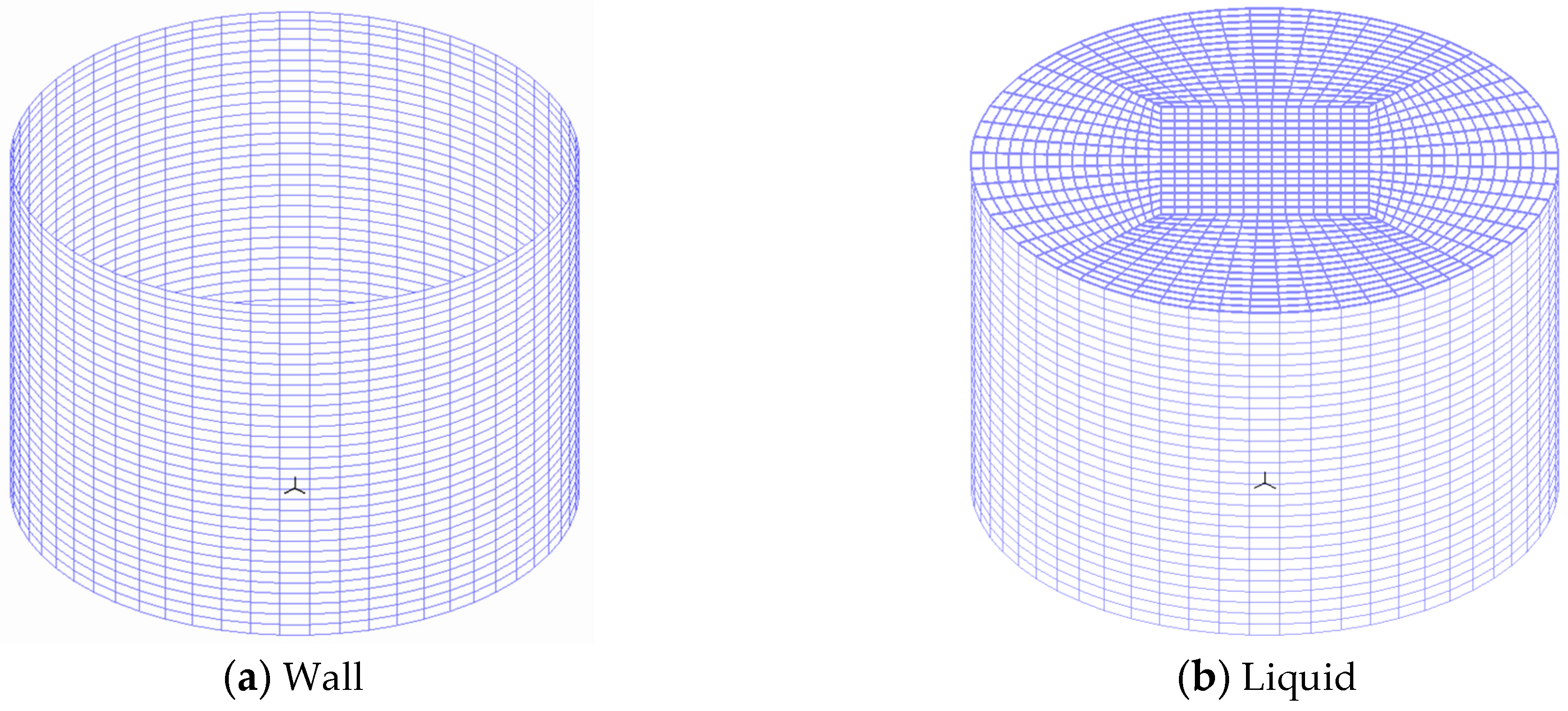
The ADINA finite element analysis software was employed to establish a finite element model for the liquid-solid coupling structure, aiming to study the dynamic response patterns of LSS. This study constructed a 1:1 scale model of LSS. Given that LSS is a typical spatial thin-walled structure, SHELL elements were used to simulate the wall panels during model creation. The liquid elements use potential-based fluid elements, and 3-D FLUID elements are used for simulation. The soil material is modeled using 3-D SOLID elements, with the material being loess. The soil constitutive model adopts the Mohr–Coulomb model. The calculation depth of the soil in this paper is chosen to be 20 m, and the length and width of the foundation soil model are both taken as 60 m. Spring elements are used to simulate the three-dimensional viscoelastic artificial boundaries of the foundation nodes, as illustrated in Figure 2.
The modal response of the liquid storage tank structure under 100% liquid storage condition can reveal the dynamic response pattern of the liquid storage tank structure under the action of earthquake forces. In order to better obtain the modal response pattern of the liquid storage tank structure, a liquid-solid coupling analysis model of the structure is established to analyze the liquid-solid coupling modal response of the liquid storage tank structure in the full liquid state, and the first four orders of liquid–solid coupling modal response are obtained as shown in Figure 3.
From Figure 3, which shows the coupled modal response of the liquid storage tank and the liquid, it can be observed that under the coupled action of the liquid and the structure, the sloshing of the liquid includes not only the vertical displacement of the liquid surface but also local splashing phenomena. In the third and fourth modes, the shell structure also undergoes local deformation. The first and second modes are mainly dominated by the sloshing of the liquid, while the third and fourth modes are primarily caused by the deformation of the storage tank that leads to the sloshing of the liquid.

3. Dynamic Response of Local Foundation Failure

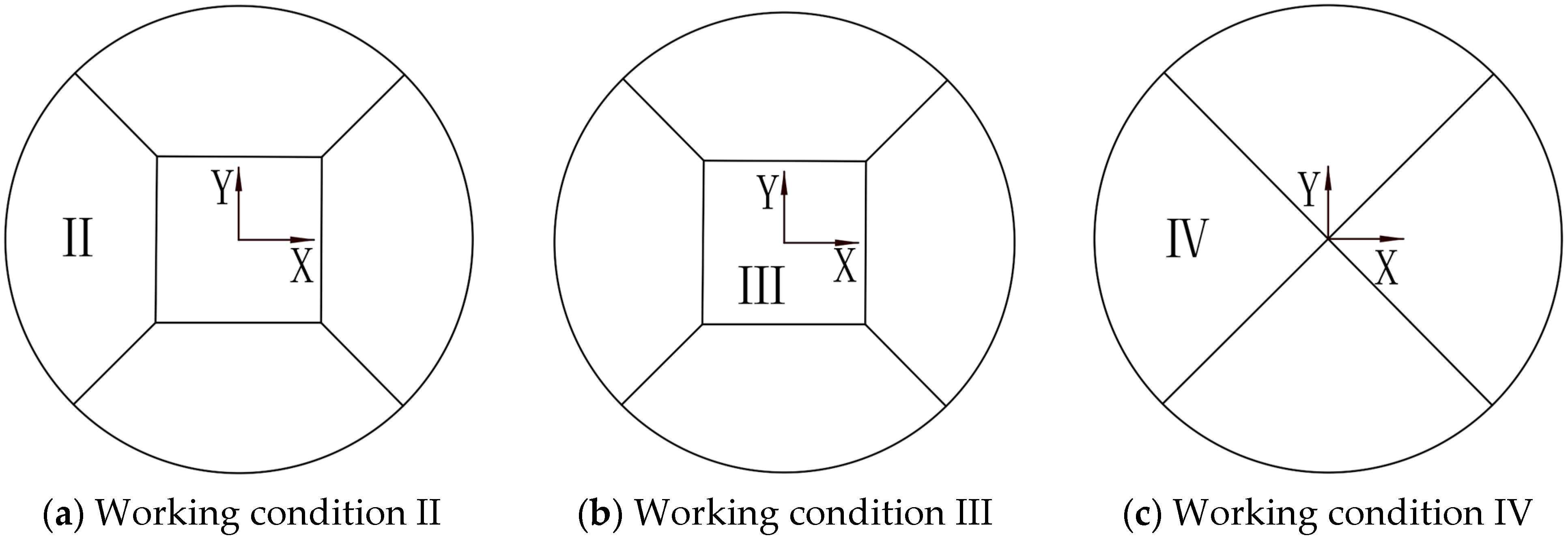
To accurately simulate the dynamic response patterns of LSS following foundation failure, three scenarios of foundation collapse were analyzed: local foundation collapse at the edge of LSS bottom (working condition II), foundation collapse at the center of LSS bottom (working condition III), and foundation collapse affecting one-fourth of LSS bottom (working condition IV). Under the action of the amplitude-modulated El Centro seismic motion (adjusted to a peak ground acceleration of 0.4 g), this study examines the dynamic response of LSS. The areas of foundation failure for the three conditions are as follows: working condition II: 66 m2; working condition III: 50 m2; and working condition IV: 78.5 m2. This setup is illustrated in Figure 4.

3.1. Dynamic Response of LSS under Working Condition II

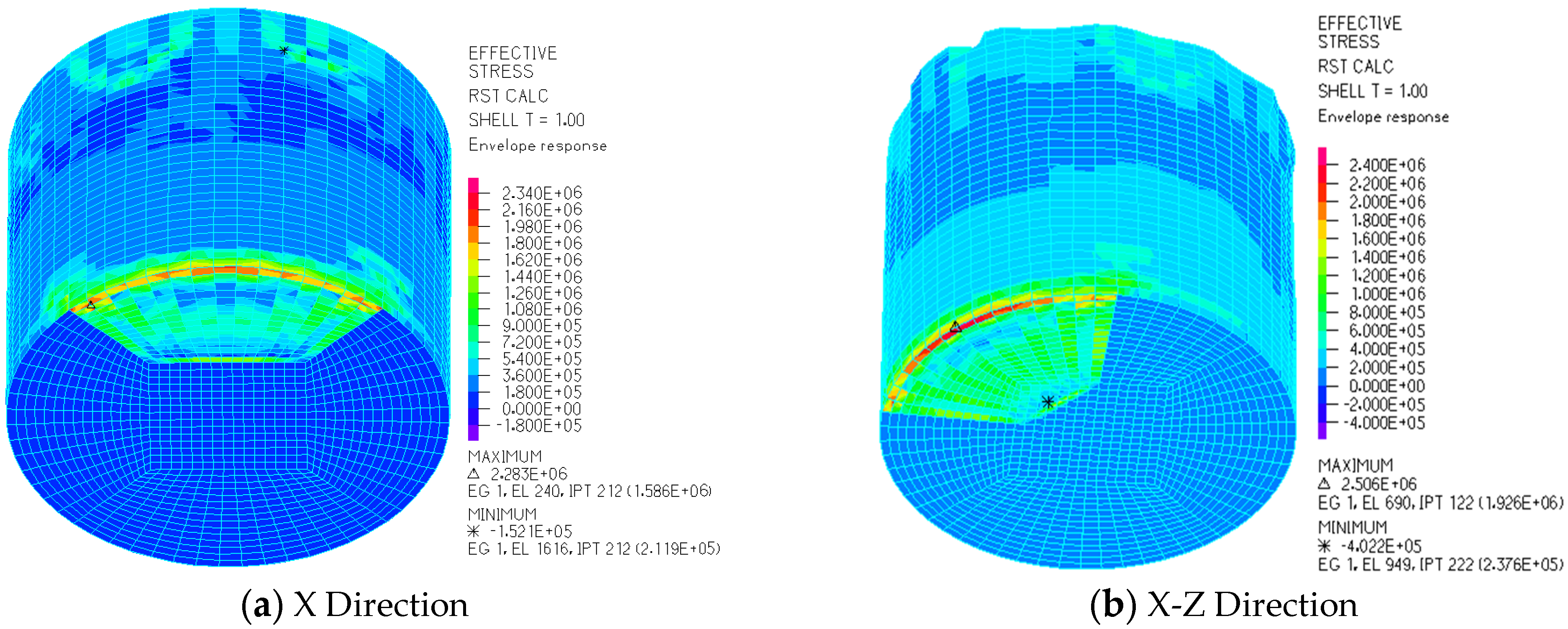
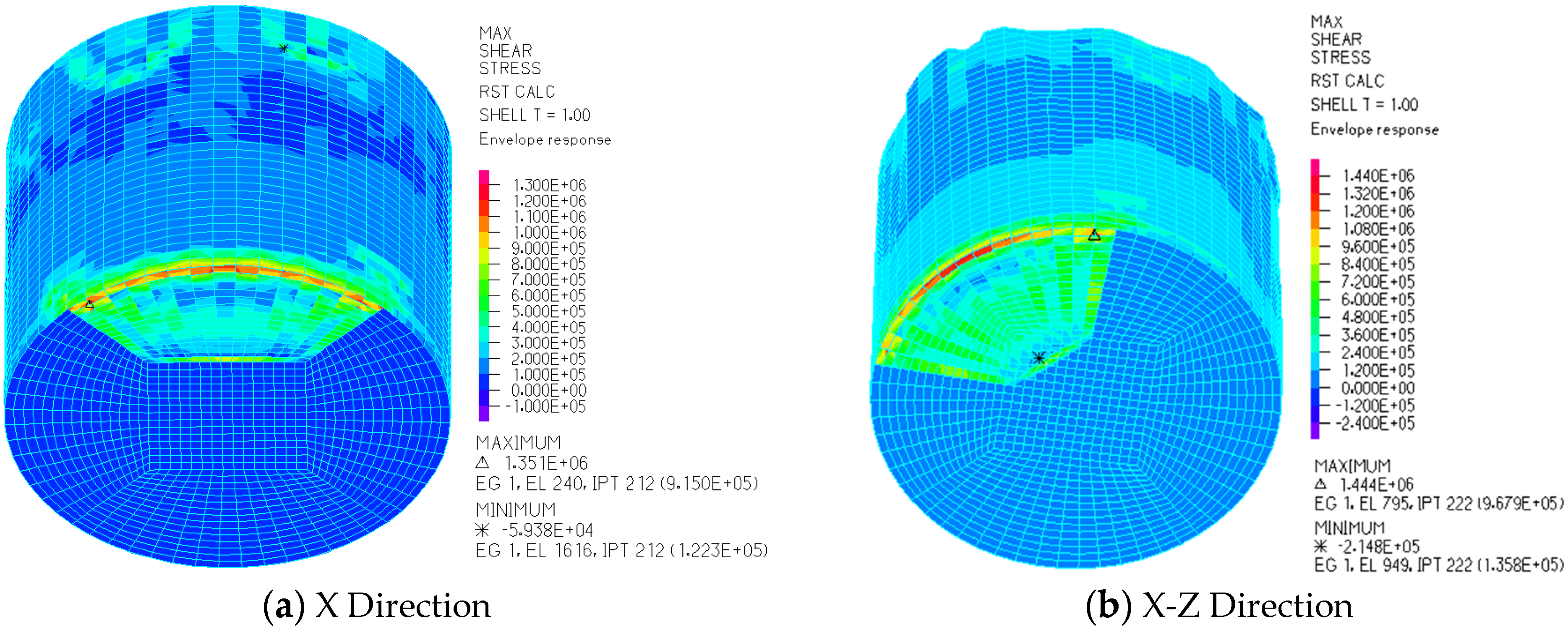
Figure 5, Figure 6 and Figure 7 show the dynamic response results of LSS under working condition II. Figure 5a, Figure 6a and Figure 7a are the result of applying seismic excitation in the X-axis direction, and Figure 5b, Figure 6b and Figure 7b are the result of the simultaneous application of seismic excitation in the direction of the X-Z-axis.
Figure 5 shows the equivalent stress envelope diagram of the wall under working condition II. It can be seen from the diagram that when the seismic excitation is applied in the X direction, the maximum equivalent stress of the wall is 2.28 MPa, and the minimum equivalent stress is −0.15 MPa; when the seismic excitation is applied in the X-Z direction, the maximum equivalent stress of the wall is 2.51 MPa, and the minimum equivalent stress is −0.40 MPa. Under the action of these two earthquakes, the maximum equivalent stress of the wall occurs at the edge of the foundation failure area, while the position of the minimum value is quite different, and the difference amplitude in the two cases is quite different.
Figure 6 shows the maximum shear stress envelope for LSS under working condition II. From the figure, it can be observed that when seismic excitation is applied in the X direction, the maximum shear stress is 1.35 MPa and the minimum shear stress is −0.06 MPa. When seismic excitation is applied in the X-Z direction, the maximum shear stress is 1.44 MPa and the minimum shear stress is −0.21 MPa. The locations where these extreme values occur are similar to those of the equivalent stress.
Figure 7 shows the liquid sloshing wave height envelope for LSS under working condition II. From the figure, it can be seen that under the two types of seismic excitation, the maximum sloshing wave heights of the liquid in LSS are 3.54 m and 3.46 m, both occurring at the center area of the liquid surface. The minimum values are −2.93 m and −3.33 m, respectively, and the locations of these extreme values are similar.

3.2. Dynamic Response of LSS under Working Condition III

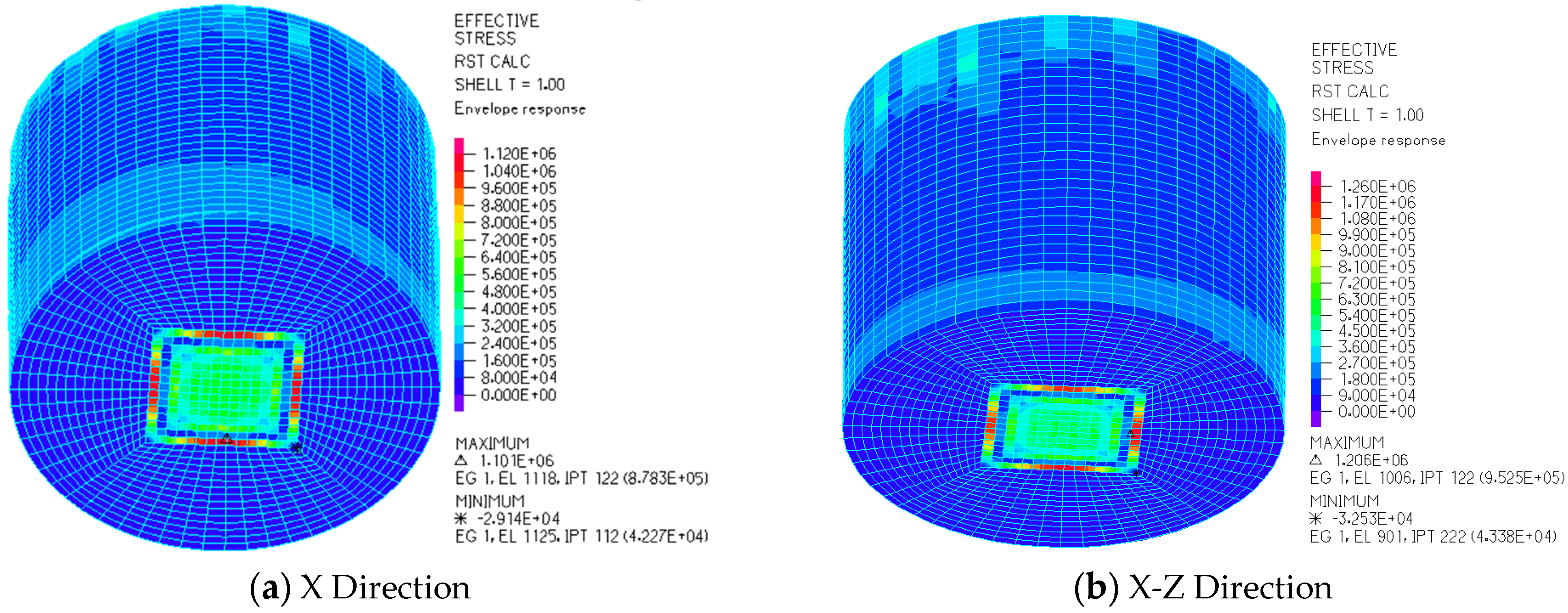
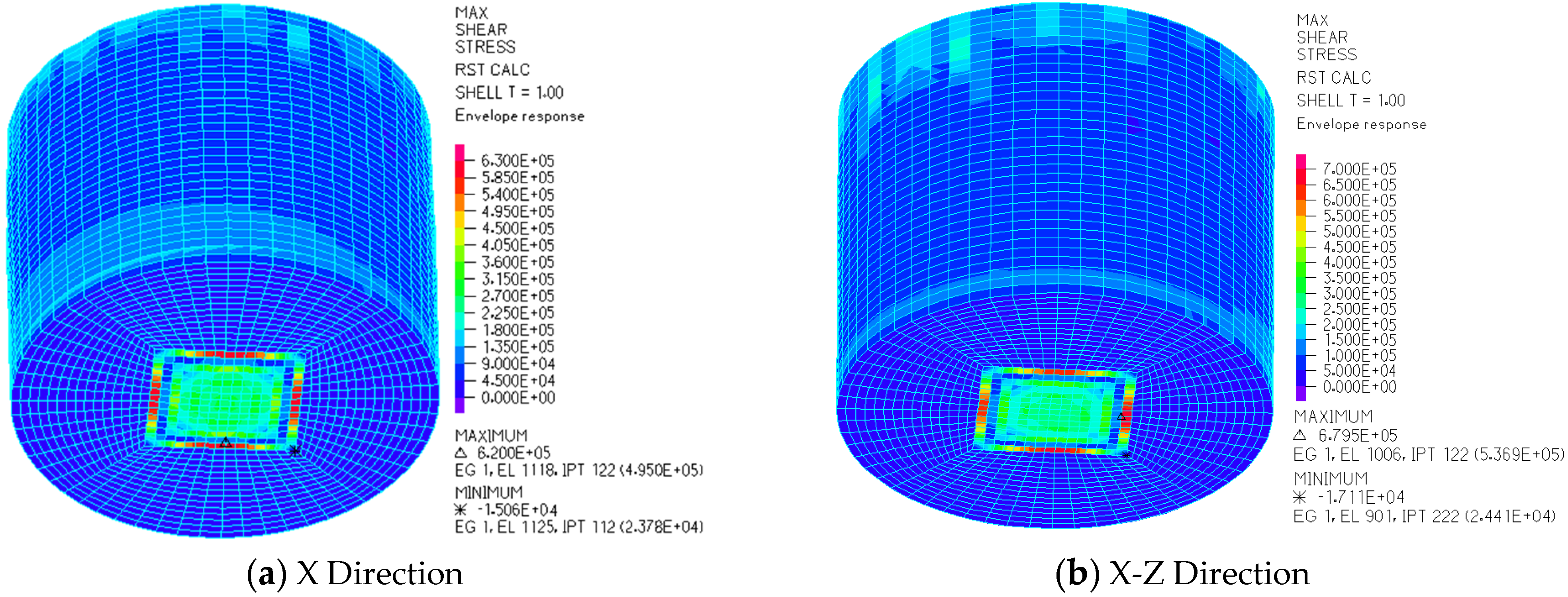
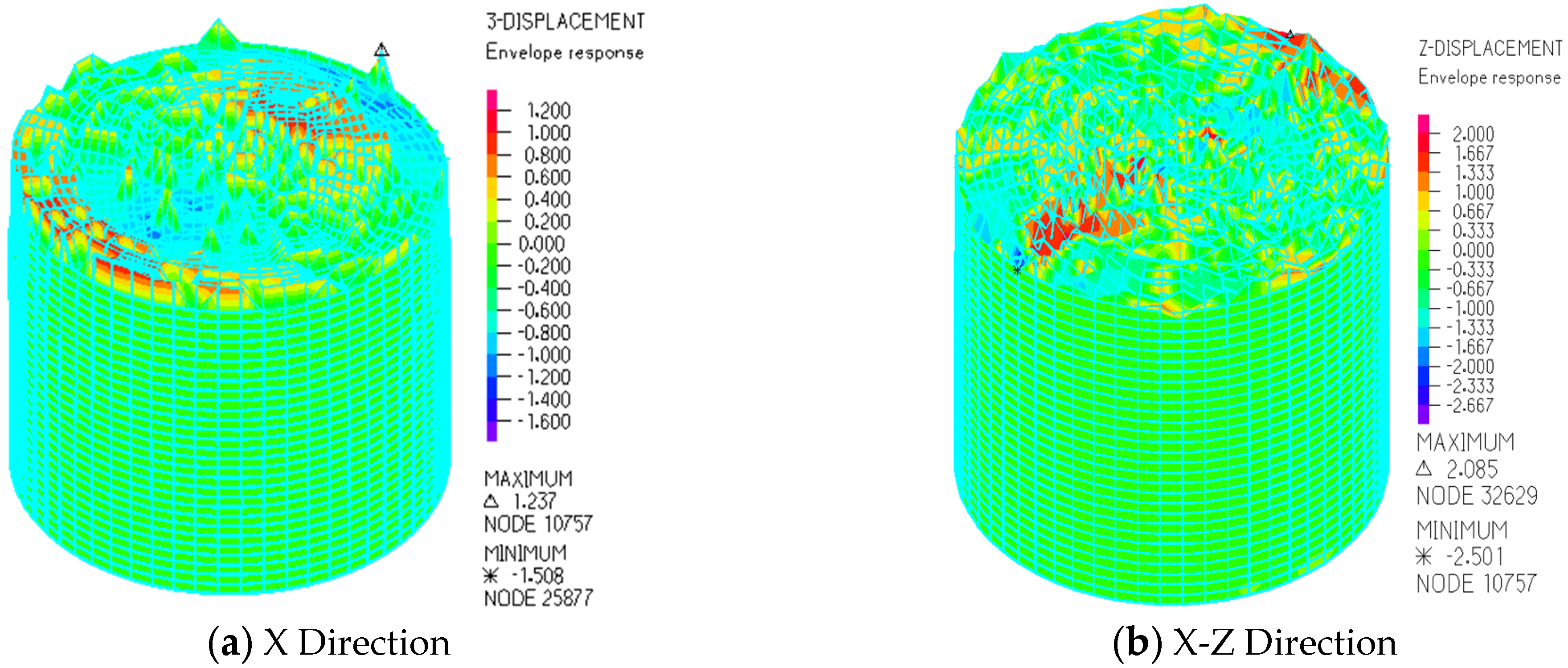
Figure 8, Figure 9 and Figure 10 show the dynamic response results of LSS under working condition III. Figure 8a, Figure 9a and Figure 10a present the results after applying seismic excitation in the X-axis direction, and Figure 8b, Figure 9b and Figure 10b present the results after simultaneously applying seismic excitation in the X-Z-axis directions.
Figure 8 shows the equivalent stress envelope of the wall under working condition III. From the figure, it can be seen that when seismic excitation is applied in the X direction, the maximum equivalent stress on the wall is 1.10 MPa, and the minimum equivalent stress is −0.03 MPa. When seismic excitation is applied in the X-Z direction, the maximum equivalent stress on the wall is 1.21 MPa, and the minimum equivalent stress is −0.03 MPa. Under both types of seismic excitation, the extreme values of the equivalent stress on the wall occur at the edge of the foundation failure area.
Figure 9 shows the maximum shear stress envelope of the wall under working condition III. From the figure, it can be seen that when seismic excitation is applied in the X direction, the maximum shear stress is 0.62 MPa, and the minimum shear stress is −0.02 MPa. When seismic excitation is applied in the X-Z direction, the maximum shear stress is 0.68 MPa, and the minimum shear stress is −0.02 MPa. The locations where these extreme values occur are similar to those of the equivalent stress.
Figure 10 shows the liquid sloshing wave height envelope of LSS under working condition III. From the figure, it can be seen that under the two types of seismic excitation, the maximum sloshing wave heights of the liquid in the storage structure are 1.27 m and 2.08 m, respectively, and the minimum values are −1.51 m and −2.50 m, respectively. These extreme values all occur at the edge of the liquid surface.

3.3. Dynamic Response of LSS under Working Condition IV

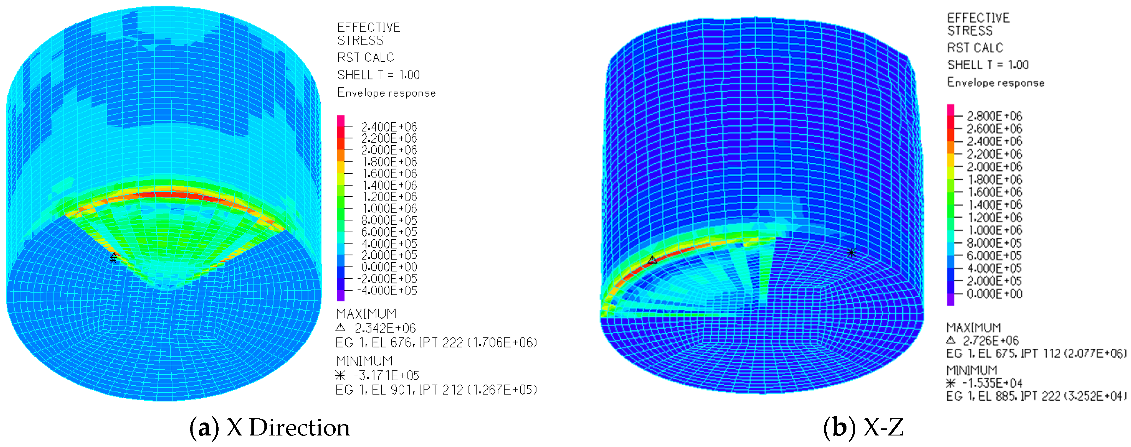
Figure 11, Figure 12 and Figure 13 show the dynamic response results of LSS under working condition IV. Figure 11a, Figure 12a and Figure 13a present the results after applying seismic excitation in the X-axis direction, and Figure 11b, Figure 12b and Figure 13b present the results after simultaneously applying seismic excitation in the X-Z-axis directions.
Figure 11 shows the equivalent stress envelope of the wall under working condition IV. From the figure, it can be seen that when seismic excitation is applied in the X direction, the maximum equivalent stress on the wall is 2.34 MPa, and the minimum equivalent stress is −0.32 MPa, with the extreme values occurring very close to each other. When seismic excitation is applied in the X-Z direction, the maximum equivalent stress on the wall is 2.73 MPa, and the minimum equivalent stress is −0.02 MPa, with the extreme values occurring at the edge of the foundation.
Figure 12 shows the maximum shear stress envelope of the wall under working condition IV. From Figure 12a, it can be seen that the maximum shear stress is 1.32 MPa, and the minimum shear stress is −0.19 MPa. From Figure 12b, the maximum shear stress is 1.54 MPa, and the minimum shear stress is −0.01 MPa.
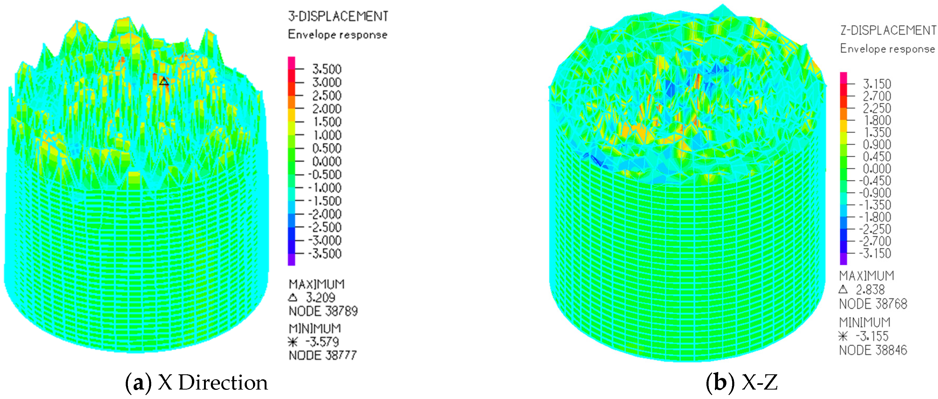
Figure 13 shows the liquid sloshing wave height envelope of LSS under working condition IV.
From the figure, it can be observed that the maximum values of liquid sloshing are 2.84 m and 3.21 m, respectively, while the minimum values are −3.16 m and −3.58 m, respectively. This indicates that the structural dynamic response is more pronounced when seismic excitation is applied in the X-Z direction.

4. Displacement Dynamic Response Rule of LSS

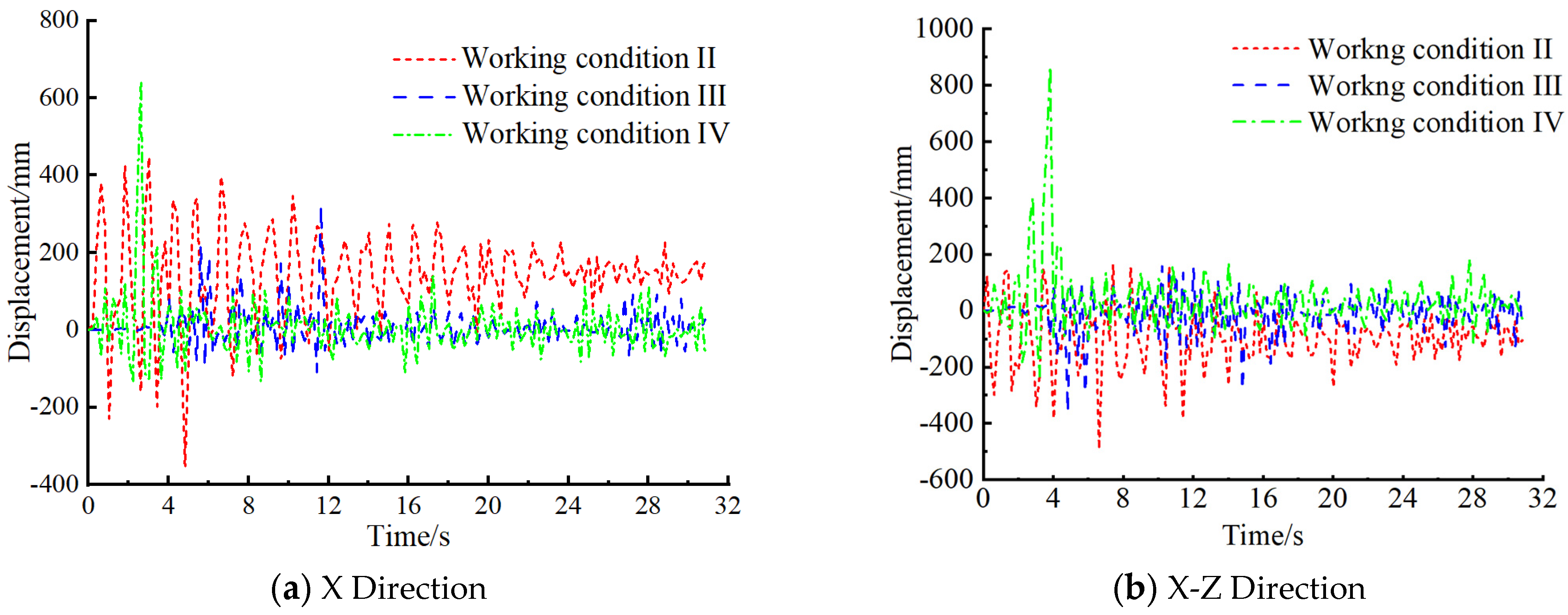
To more accurately investigate the influence of foundation collapse on the dynamic response of LSS in loess areas under seismic excitation, the displacement response of the wall under different conditions was extracted to analyze the dynamic response patterns. Figure 14a presents the results after applying seismic excitation in the X-axis direction, while Figure 14b presents the results after simultaneously applying seismic excitation in the X-Z-axis directions.
Figure 14 depicts the schematic diagram of the displacement response patterns of the wall. From Figure 14a, it can be observed that under working condition II, the maximum displacement of the wall is 466.8 mm; under working condition III, the maximum displacement of the wall is 322.6 mm; and under working condition IV, the maximum displacement of the wall is 643.7 mm.
From Figure 14b, it can be seen that under working condition II, the maximum displacement of the wall is −490.6 mm; under working condition III, the maximum displacement of the wall is −358.8 mm; and under working condition IV, the maximum displacement of the wall is 867.4 mm.
It can be concluded that the seismic response of LSS is directly influenced by factors such as the location of foundation failure and the direction of seismic loading.

5. Conclusions

(1)
Different types of foundation failure conditions lead to varied dynamic response results of LSS, causing different increases in wall displacement and potentially resulting in structural failure due to excessive deformation. Therefore, ensuring the safety of the foundation in loess areas is particularly crucial for the safe operation of LSSs.
(2)
The foundation collapse of LSS leads to varying degrees of increase in equivalent stress, maximum shear stress, wall displacement, and liquid sloshing wave height. These increases vary depending on different conditions.
(3)
Under seismic loading, the dynamic response patterns of LSSs differ across different conditions. Comparing the dynamic response results under different conditions, working condition III has a relatively minor impact on the results, while working condition IV has the greatest impact on the structural dynamic response.
(4)
The dynamic response patterns of LSSs are directly related to the direction of seismic loading. Compared to the seismic excitation along the X-axis, the structural dynamic response is more pronounced when simultaneously subjected to seismic excitation along the X-Z-axis.

Author Contributions

W.H. contributed to the investigation, conceptualization, methodology, software, and writing of the original draft. X.C. (Xianhui Cao) contributed to the conceptualization, formal analysis, methodology, writing, review, and editing. H.X. contributed to the conceptualization, methodology, and software. H.S. contributed to the validation, data curation, writing, review, and editing. X.C. (Xuansheng Cheng) assisted in investigation, conceptualization, methodology, resources, and supervision. All authors have read and agreed to the published version of the manuscript.

Funding

This research received no external funding.

Institutional Review Board Statement

Not applicable.

Informed Consent Statement

Not applicable.

Data Availability Statement

All data, models, and code generated or used during the study appear in the submitted article.

Conflicts of Interest

Author Wenji Huang was employed by the company Gansu Dayu Water-Saving Group Water Resources and Hydropower Engineering Co., Ltd. The authors declare that there are no conflicts of interest regarding the publication of this paper.

References

  1. Westergaard, H.M. Water pressures on dams during earthquakes. Am. Soc. Civ. Eng. 1933, 98, 418–433. [Google Scholar] [CrossRef]
  2. Housner, G.W. Dynamic pressure on accelerated fluid container. Bull. Seismol. Soc. Am. 1957, 47, 15–35. [Google Scholar] [CrossRef]
  3. Haroun, M.A. Vibration studies and tests of liquid storage tanks. Earthq. Eng. Struct. Dyn. 1983, 11, 179–206. [Google Scholar] [CrossRef]
  4. Livaoglu, R. Investigation of seismic behavior of fluid-rectangular tank-soil/foundation systems in frequency domain. Soil Dyn. Earthq. Eng. 2008, 28, 132–146. [Google Scholar] [CrossRef]
  5. Tang, Y.G.; Zhang, Z.S.; Li, C.S.; Yang, C.H. Fluid velocity potential and simplified model for unanchored storage tanks. J. Water Resour. 1997, 9, 42–47. [Google Scholar]
  6. Hwang, T.; Ting, K. Boundary element method for fluid-structure interaction problems in liquid storage tanks. Journal of pressure Vessel Technology. Trans. ASME 1989, 111, 435–440. [Google Scholar]
  7. Fan, X.Z.; Zheng, T.X.; Wang, W.; Wu, L.Y.; He, X. Simulation analysis of “elephant foot” deformation of vertical liquid storage tank wall under seismic action. Earthq. Eng. Eng. Vib. 2007, 27, 104–109. [Google Scholar]
  8. Sun, J.G.; Wang, Z.; Wang, X.N.; Yang, Y. Finite element analysis of three-dimensional seismic response of floating storage tank. Earthq. Eng. Eng. Vib. 2008, 28, 191–199. [Google Scholar]
  9. Zhang, Y.; Guan, Y.H. Seismic Response analysis of large liquid storage tanks. Appl. Mech. Mater. 2012, 1799, 2490–2493. [Google Scholar] [CrossRef]
  10. Liu, D.Y.; Fang, Z. Experimental and Numerical simulation investigation on dynamic response of liquid storage tanks under seismic excitations. Appl. Mech. Mater. 2014, 2963, 763–766. [Google Scholar] [CrossRef]
  11. Xi, C.S.; Zeng, X.W.; Pu, M. Analysis of dynamic characteristics and seismic response of vertical cylindrical oil storage tank. Pet. Eng. Constr. 2016, 42, 11–17. [Google Scholar]
  12. Zhang, R.; Cheng, X.; Guan, Y.; Tarasenko, A.A. Seismic response analysis of an unanchored vertical vaulted-type tank. Earthq. Struct. 2017, 13, 67–77. [Google Scholar]
  13. Cheng, X.S.; Jing, W.; Gong, L.J. Dynamic responses of a sliding base-isolated RLSS considering free surface liquid sloshing. KSCE J. Civ. Eng. 2018, 22, 4964–4976. [Google Scholar] [CrossRef]
  14. Cheng, X.; Liu, B.; Cao, L.; Yu, D.; Feng, H. Dynamic response of a base-isolated CRLSS with baffle. Structural Engineering and Mechanics. Int. J. 2018, 66, 411–421. [Google Scholar]
  15. Cheng, X.S.; Jing, W.; Li, D. Dynamic response of concrete tanks under far-field, long-period earthquakes. Proc. Inst. Civ. Eng.—Struct. Build. 2019, 174, 1–37. [Google Scholar] [CrossRef]
  16. Luo, D.; Liu, C.; Sun, J.; Cui, L.; Wang, Z. Sloshing effect analysis of liquid storage tank under seismic excitation. Structures 2022, 43, 40–58. [Google Scholar] [CrossRef]
  17. Jing, W.; Shen, J.; Cheng, X.; Yang, W. Seismic responses of a liquid storage tanks considering structure-soil-structure interaction. Structures 2022, 45, 2137–2150. [Google Scholar] [CrossRef]
  18. Hernandez, D.; Larkin, T.; Chouw, N. Lid induced sloshing suppression and evaluation of wall stresses in a liquid storage tanks including seismic soil-structure interaction. Earthq. Eng. Struct. Dyn. 2022, 51, 2708–2729. [Google Scholar] [CrossRef]
  19. Wang, J.; Guo, T.; Du, Z.; Yu, S. Shaking table tests and parametric analysis of dynamic interaction between soft soil and structure group. Eng. Struct. 2022, 256, 114041. [Google Scholar] [CrossRef]
  20. Kumar, H.; Saha, S.K. Effects of soil-structure interaction on seismic response of fixed base and base isolated liquid storage tanks. J. Earthq. Eng. 2022, 26, 6148–6171. [Google Scholar] [CrossRef]
  21. Jaramillo, F.; Almazán, J.L.; Colombo, J.I. Effects of the anchor bolts and soil flexibility on the seismic response of cylindrical steel LSSs. Eng. Struct. 2022, 263, 114353. [Google Scholar] [CrossRef]
  22. Sun, Y.; Cui, L.F.; Sun, J.G.; Cheng, L.H. Energy dissipation damping analysis of vertical storage tanks in service based on SMA dampers. Struct. Eng. 2021, 37, 64–76. [Google Scholar]
  23. Tian, L.L.; Liang, X.Q. Analysis of causes of uneven settlement of storage tank groups on deep backfill foundations and correction and reinforcement treatment. Found. Treat. 2022, 4, 414–422. [Google Scholar]
  24. Li, B.; Meng, M.J.; Shao, W.T. Numerical simulation of uneven subsidence of soft ground foundation of oil storage tank based on finite element analysis. Urban Roads Bridg. Flood Control 2022, 279, 191–196. [Google Scholar]
  25. Liu, Z.; Zhang, H.Y.; Qin, K. Deformation and force analysis of large liquid storage tank and foundation ring wall based on FLAC3D. Guangdong Chem. Ind. 2022, 49, 172–174+184. [Google Scholar]
  26. Wu, J.H. Analysis of Seismic Dynamic Response of LSS under Uneven Settlement of Foundation; Zhejiang University: Hangzhou, China, 2021. [Google Scholar]
  27. China Academy of Building Research. Code for Seismic Design of Buildings, 2016th ed.; Architecture & Building Press: Beijing, China, 2016. [Google Scholar]
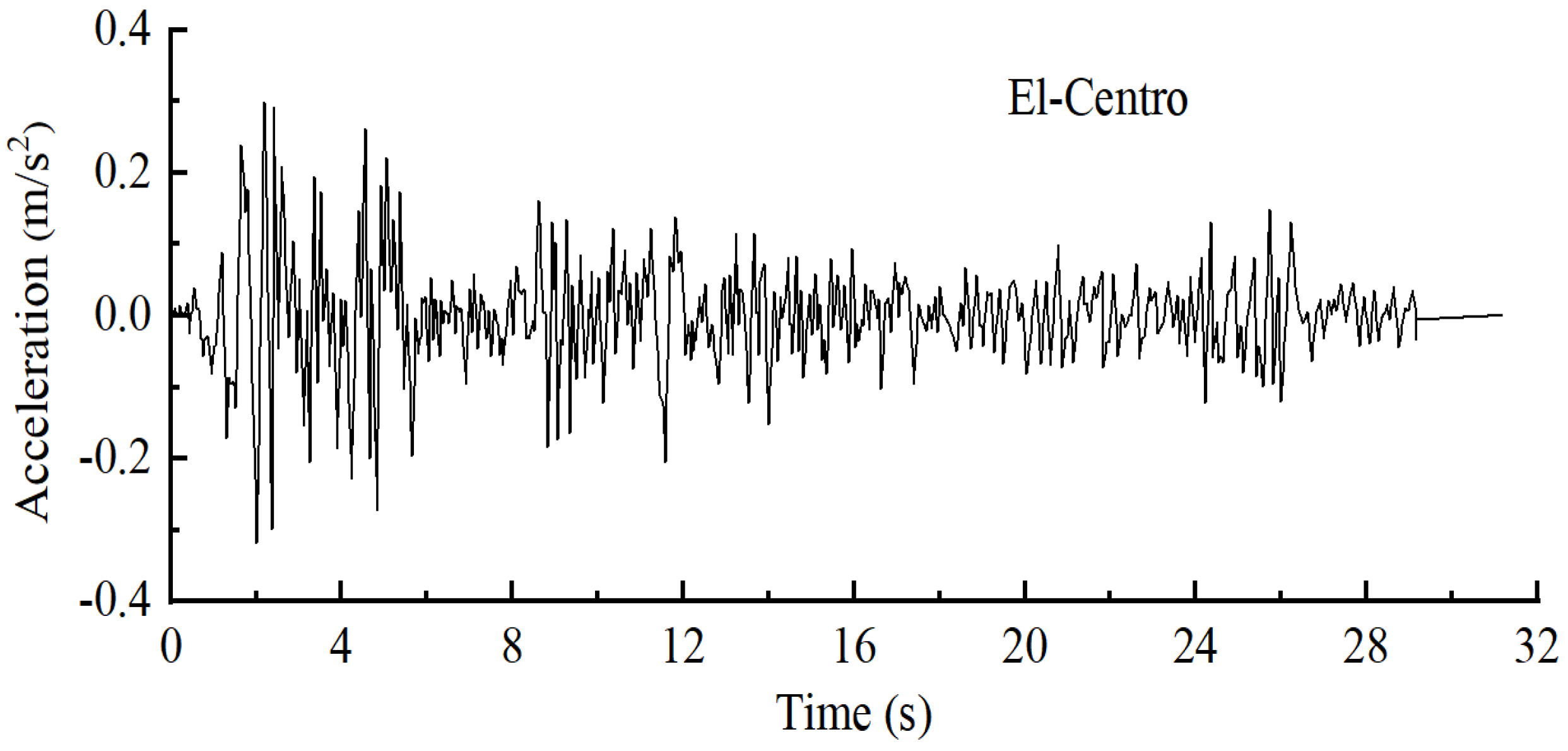
Figure 1. El-Centro wave time history curve.
Applsci 14 08993 g001
Figure 2. Finite element analysis model. (The symbol in the center of the figure is the coordinate system, with the z-axis positive upward, the x-axis positive to the left, and the y-axis positive to the right).
Applsci 14 08993 g002
Figure 3. Liquid-structure interaction modal response.
Applsci 14 08993 g003
Figure 4. Schematic diagram of foundation failure area.
Applsci 14 08993 g004
Figure 5. The equivalent force envelope of the wall plate for working condition II.
Applsci 14 08993 g005
Figure 6. The maximum shear stress envelope of the wall plate for working condition II.
Applsci 14 08993 g006
Figure 7. The liquid sloshing wave height for working condition II.
Applsci 14 08993 g007
Figure 8. The equivalent force envelope of the wall plate for working condition III.
Applsci 14 08993 g008
Figure 9. The maximum shear stress envelope of the wall plate for working condition III.
Applsci 14 08993 g009
Figure 10. The liquid sloshing wave height for working condition III.
Applsci 14 08993 g010
Figure 11. The equivalent force envelope of the wall plate for working condition IV.
Applsci 14 08993 g011
Figure 12. The maximum shear stress envelope of the wall plate for working condition IV.
Applsci 14 08993 g012
Figure 13. The liquid sloshing wave height for working condition IV.
Applsci 14 08993 g013
Figure 14. The displacement response rule of the wall plate of the storage liquid tank.
Applsci 14 08993 g014
Table 1. Calculation parameters.
Exploration
Well Number
Soil Layer Distribution Depth
/m
Self-Weight Collapsibility Content Δzs/mmCollapsibility Value
Δs/mm
Collapsible Level
ZK47.2578.75177.98Grade II self-weight
ZK66.750.00224.13Grade I non-weight
ZK147.250.00237.38Grade I non-weight
Table 2. Soil parameters.
SoilLayer Thickness
h/m
Density ρ
/kg/m3
Elastic Modulus E/MPaPoisson’s Ratio νCohesion c/kPaInternal Friction Angle ψ
Plain fill3.816464.70.38814
Silty clay2.417905.520.301522
Pebble6.32100500.17038
Strongly weathered sandstone42230450.23230
Moderately weathered sandstone43.52250500.202532
Disclaimer/Publisher’s Note: The statements, opinions and data contained in all publications are solely those of the individual author(s) and contributor(s) and not of MDPI and/or the editor(s). MDPI and/or the editor(s) disclaim responsibility for any injury to people or property resulting from any ideas, methods, instructions or products referred to in the content.