Abstract
The study aims to eliminate the effect of coalescing filter blocking due to on–off operation by changing the wetting properties of the non-woven fiberglass filter media through their chemical modification with the use of a polydimethylsiloxane (PDMS) solution in hexane and a few commercial products that give the surface oleophobic properties. The best results—high separation efficiency, no redispersion of droplets at the outlet, and low flow resistance—were obtained for materials coated by immersion in a 0.2% PDMS solution, for which a reduction in oleophilicity was found, but the material was not oleophobic and still moderately wetted with the test liquid. The corresponding static contact angle with the VG-46 rotary compressor oil measured on the flat borosilicate glass wafer made of the same material as the fiberglass media was equal to 54° for the PDMS dip-coated surface. Moreover, the good stability of the applied polymer on the material surface was confirmed by the SEM imaging, the FTIR analysis, and maintaining a high performance in multiple tests run for a single coalescing element.
1. Introduction
The separation of components in gas–liquid systems, where the liquid is the dispersed phase, is important in industrial practice. There are many reasons for the need to separate such systems. These include the purification of gas products (being final products with given parameters meeting the specification or components for further processes), ensuring the protection of compressors, catalytic, or sorption beds against the negative impact of drops constituting the liquid phase, reducing the emission of aerosol drops into the natural environment or surroundings, e.g., the workplace, etc. An effective, easy-to-implement, and economically beneficial method of eliminating dispersed liquid pollutants from gas streams is the use of gas–liquid coalescing filters. Separation technologies using this type of filter have been used for many years. The process principles comprising gas–liquid and liquid–liquid coalescers are quite similar—both systems have been studied experimentally and theoretically. Understanding the mechanisms of the process is supported by various models describing its course, taking into account the deposition of drops on the structure’s fibers, the connection of drops with ones deposited on the fibers or with each other in the flow, the transport of drops through the porous structure to the outlet, and finally the detachment of droplets or drainage of liquid from the outlet surface filter [1]. The operational parameters as well as the structural and surface properties of the fibrous bed have a key impact on the nature of the two-phase flow, which determines the effectiveness of capturing and combining droplets carried by the flow and the effective drainage of the liquid at the outlet, where the gravitational separation takes place [2,3,4].
In recent years, the film-channel model was developed, which describes the process principles and, what is very important, clarifies the effect of material wettability on the saturation profiles across the media [5,6,7]. The model was validated in numerous research studies; therefore, it accounts for a well-established knowledge regarding the operation of coalescing filters. Few other research studies focus on the effect of the drainage layer in the coalescing filters, including its effects on the saturation profiles, the pressure drop, and the separation performance [8,9,10,11]. Referring to the drainage phenomena, a numerical analysis coupled with AFM measurements for various types of fiber and droplet conformation was published in the literature [12,13]. These works were focused on the measurements of force required to detach a droplet from wettable and non-wetted fibers (droplets on single filaments or on fiber intersections). Many research studies refer to the effect of fiber wettability on the performance of coalescing filters [14,15,16,17], including the influence of mesh spacers’ location on their operation [17].
Moreover, literature studies on the influence of the presence of liquid retained inside the filter on geometric changes in its structure as a result of surface tension forces were published in recent years [18]. This effect may be important for structures with loose fiber packing (i.e., high porosity) and low dynamic stability of the structure. In the case of multi-layer structures composed of separately produced layers, the presence of liquid may affect the spaces between them in a sandwich, which then translates into the overall effectiveness of the filter [19].
There are many studies related to gas–liquid coalescer operation improvement by modification of fibrous material. However, the papers usually refer to typical testing procedures, including saturation at a steady flow rate. In such flow conditions, the possible detrimental effects of interrupted operation are not revealed, which can be of high importance in industrial practice. The presented research addresses this research gap and focuses on the elimination of step changes in pressure drop and the accompanying decrease of droplet separation efficiency due to the on–off operation.
As described above, an important issue is the possibility of capillary transport occurring inside the structure in conditions of no flow (no resistance forces acting on the liquid inside the filter). Such liquid movement affects the filter’s operating conditions immediately after restarting the system, and if capillary interactions and adhesion to the structure are sufficiently high, the changes may be irreversible. This phenomenon was observed during experiments, where it was found to have an adverse effect on the operation of coalescing filters. The work concerns the interpretation of the causes and appropriate modification of the filtration structure, which allows for minimizing the increase in flow resistance after resuming the operation of the filter saturated with the removed liquid.
2. Problem Statement
Most of the presented studies on gas–liquid coalescing filters concern the assessment of their efficiency in the initial state or, more importantly, from the practical point of view, after reaching saturation and stabilizing the pressure drop value (which is achieved for an ideal system without the content of solid particles). In their work, Bredin and Mullins attempted to assess the change in the efficiency of aerosol droplet separation caused by interruptions in operation and draining the oil from elements during downtime [20]. They presented the results in subsequent on–off cycles for different pauses of the flow, different modes of saturation of elements with the oil, and cleaning using the reversed flow. For selected structures, they reached the final steady-state values at a similar level, regardless of the system operation mode (saturation procedure and length of the break without aerosol flow). Kolb and Kasper discussed the “dP creep” and the liquid rearrangement inside the filter media for different flow velocities, loading rates, and saturation scenarios (i.e., starting from dry/clean filter or presaturated) [21]. They concluded that reaching steady-state saturation can correspond to different dP values depending on the experimental conditions and properties of filter media. Moreover, they advised that the saturation reaches a stable endpoint sooner than the pressure drop, and the creeping of the dP value may continue for the filter lifetime.
The presented research focuses on the elimination of step changes in pressure drop and the accompanying decrease of the droplet separation efficiency due to the on–off operation. These flow interruptions were forced already in the initial stage during the saturation of the filters. The stepwise changes of the pressure drop were observed, which, as it turned out during the tests, were irreversible—i.e., the terminal values of flow resistance (pressure drop) for elements without modification of filters and continuous operation of the system were much lower than when airflow was interrupted and restarted multiple times. In extreme cases, this led to exceeding the range of the dP sensor before reaching a full saturation of the filter with the oil accumulated inside. For some applications, this may be the reason for exceeding the permissible parameters and the need to replace the element with a “clean” one, which could turn out to be a temporary solution anyway. It was concluded that the cause for this behavior is the transport of oil inside the porous structure due to capillary interactions. Therefore, research was focused on the affinity change of the liquid (oil) to the material surface by the application of chemical coatings to reduce or eliminate the transport of oil in the structure when the filtration system is down. In a typical design, the coalescing filters consist of the coalescence media and a drain layer. A major part of the pressure drop is related to the coalescence media, where the capillarity plays a much bigger role. Hence, in this work, the additional layer of media facilitating the drainage was not included in the filters used in the experimental program for flat panels to isolate the effects of the coalescing structure.
3. Materials and Methods
The commercial fiberglass filtration material was used. The structure consists of two different layers of glass media, which significantly differ in the diameter of fibers. Based on the analysis of SEM images (microscope Phenom G2), the distribution of fiber diameters in each layer was determined, and the overall grammage was evaluated by weighting the ϕ = 150 mm circular panels (see Table 1). The example SEM images of both layers are shown in Figure 1.

Table 1.
Specification of the filter media.
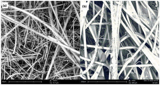
Figure 1.
The SEM images of fiberglass media used in experiments: (a) the first layer (on the inlet side of the filter); (b) the second layer (located on the downstream side of the filter).
3.1. Filter Media Coating
The modification of filter material was focused on altering the affinity of the native structure to the oil. Therefore, the effect of coating was referred to the original material. The treatment procedures can be divided into two main groups:
- Dip-coating in the commercial solutions, which change the surface wettability;
- Dip-coating in the polydimethylsiloxane (PDMS) solution in the hexane.
Based on Ref. (1), three different solutions purchased from NanoX GmbH, Saarbrücken, Germany were used for the dip coating: EC1206, EC5028, and EC5029. The composition of products is not revealed by the manufacturer, but it is claimed that EC1206 creates a hydrophobic and slightly oleophobic surface, while EC5028 and EC5029 provide highly oleophobic properties of a coated material. The aerograph was used to apply the solution onto filter media. The dipping time was extended to 15 min to ensure penetration of the solution into porous material, and after removing it, it was dried at 60 °C for 24 h.
Based on Ref. (2), the polydimethylsiloxane was purchased from Merck, Rahway, NJ, USA (CAS 63148-62-9), and the hexane was purchased from Pol-Aura, Morąg, Poland (analytically pure, CAS 110-54-3). Three concentrations of the PDMS in hexane were used: 0.2%, 1.0%, and 5.0% (by mass), and the immersion time of 15 min was applied. After that, the material was dried for 24 h at 60 °C.
3.2. Material Analysis
To determine the affinity of the material surface to the test liquids—the oil Tellus S2 MX 46 from Shell, London, UK and the deionized water—the contact angle measurements using goniometer OCA 25 from DataPhysics, Filderstadt, Germany were carried out. However, these measurements were performed only for contact angles above 90°, i.e., when no penetration of liquid into porous media takes place. The contact angles were also measured for the non-porous wafers made of the same grade of borosilicate glass as the fibrous material. For each material, ten measurements at different locations on the surface were performed and averaged.
To verify the presence of coatings on the material, the FTIR-ATR analyses using the Nicolet iS10 spectrophotometer, Thermo Fisher Scientific, Waltham, USA, were performed. The media observations using SEM were involved to confirm whether the filter pores are not blocked (apart from monitoring the initial dP values). For the PDMS coatings, the FTIR spectrophotometry and analysis of SEM images were also performed after the process to qualitatively confirm the presence (i.e., the stability) of the deposited layer. The oil-saturated media were washed with isopropyl alcohol to remove the oil before the analyses were carried out.
3.3. Test Rig for Gas–Liquid Coalescing Filters
The operation of the gas–liquid coalescing media was experimentally verified using the test rig equipped with two housings (two parallel branches):
- (1)
- Original HFP 2000 system from PALAS GmbH, Karlsruhe, Germany with a horizontal vessel for testing circular flat panels.
- (2)
- Additional vertical housing suitable for mounting cylindrical pleated cartridge filters, designed and delivered by Amazon Filters Ltd., Camberley, UK.
- (3)
- The system layout is schematically shown in Figure 2.
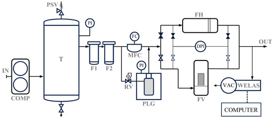 Figure 2. The experimental setup for testing gas–liquid coalescing media is as follows: COMP-rotary gas compressor; T—compressed air feed tank; F1, F2—air cleaning filters; MFC—mass flow controller; RV—reducing valve; PLG—aerosol generator; FH—horizontal filter housing (for flat media); FV—vertical filter housing (for cartridge filters); VAC—vacuum pump; WELAS—particle counter.
The system is supplied with the pressurized air from the tank (T), which is fed from the screw compressor (COMP). The air passes two cleaning filters and is split into the main line, where the flow is adjusted by the mass flow controller (MFC). The other line of compressed air goes to the aerosol generator (PLG, which stands for the “particle liquid generator”) through a reducing valve (RC), which allows for adjusting the pressure to a desired level. The aerosol is generated in a Laskin nozzle (a properly designed nozzle immersed in the oil). Then, these two lines merge, and the aerosol flows to a selected filter housing: a horizontal housing (original PALAS part for testing filter media in the form of flat panels) or a vertical housing, in which cartridge elements can be mounted. On the downstream side of the test vessels, the aerosol sample is taken for analysis using a vacuum pump (VAC), which enables the suction of aerosol throughout the chamber of particle counter WELAS 1000 (range 0.2–10.0 μm). The measurement of the inlet aerosol is carried out using the same sample line but without any filter installed in the housing. The data from the counter are transferred to the PC and analyzed using software provided by PALAS GmbH.
In experiments, the constant value of superficial velocity equal to 7.5 cm/s was used, which corresponds to the following flow rates of the supplied air:
- Eighty L/min for flat circular media of the diameter 150 mm (the horizontal filter housing, the filtration material mounted vertically),
- Three hundred sixty L/min for pleated cartridge elements of a height 90 mm, having 44 pleats and a height of pleats 10 mm (the vertical filter housing); the melt-blown drain layer made of polyester (polybutylene terephthalate—PBT) was included on the outlet: grammage ~200 g/m2, the layer thickness ~3 mm, and the average fiber diameter around ~30 mm.
The size distribution of the aerosol droplets upstream of the filter is presented in Figure 3. The inlet concentration of oil was approximately 40 mg/m3.
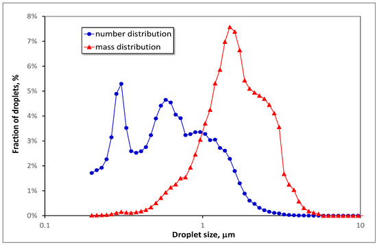
Figure 3.
Size distribution of the oil droplets upstream of the filter.
The experiment was finished approximately 3 h after the pressure drop was stabilized or when the upper limit of the dP sensor (10 kPa) was exceeded. During experiments, the flow of aerosol was stopped every 30 min for 1 min.
4. Results and Discussion
Three modifications were carried out using three types of commercial solutions purchased from NanoX: EC1206, EC5208, and EC5029. The second group of surface treatments was the PDMS from its solutions in the hexane. The coatings were applied to the fiberglass filtration material and also to the wafers made of borosilicate glass following the same procedure. The results of the static contact angle with the oil and the water droplet are presented in Figure 4. For the porous filter media, it was possible to analyze the contact angle of the sessile droplet when no liquid penetration into the material occurred, i.e., for the values of contact angle above 90°. This is why some of the measurement data with the oil shown in Figure 4b are missing.
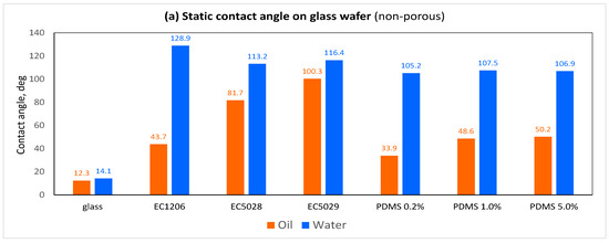
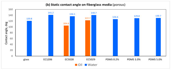
Figure 4.
Contact angles on the surface of modified materials: (a) flat non-porous glass wafer, (b) fibrous filter media made of fiberglass.
The data presented in Figure 4a show that the glass is wettable well by both test liquids: the oil and the water. However, since some additives are typically included in the fiberglass material, usually resins for integrity and sometimes other quality chemicals, the fibrous fiberglass material appeared to be impregnated. As it turned out, some kind of modification was applied in the fibrous media because the water contact angle (WCA) was above 120° and no water penetration was observed, while for the clean, non-porous wafer made of the borosilicate glass, the WCA was around 14°. Much more important values for the studied process were the contact angles with the oil (OCA) used in experiments. On the clean glass, the OCA values increased for all coatings—for EC1206, it was 43.7°; for PDMS coatings, it increased with the increasing polymer concentration in the solution: 34°, 49°, and 50° for 0.2%, 1.0%, and 5.0%, respectively. For EC5028 and EC5029, the oil contact angles reached the highest values of around 82° and 100° on the flat glass, respectively. Although the oleophobic properties correspond to the OCA above 90°, both coatings applied to the porous material caused that no oil imbibition was observed when the droplet was placed on the material (see Figure 5).
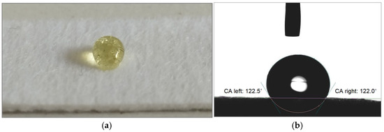
Figure 5.
The oil droplet on the oleophobic fiberglass coated with EC5029: (a) a real photo; (b) an image from a goniometer.
Although the contact angle measurements refer to the material surface, the dip-coating process from organic solvents enables efficient penetration of the solution into the material. This was confirmed by SEM imaging that the coating material was present on the surface of all fibers in the entire volume of the porous filet structure.
The FTIR-ATR analysis of the coated materials was performed. The results after subtracting the background signal for untreated material are presented in Figure 6. However, only spectra for the PDMS coatings provide a measurable absorption intensity; the PDMS formula is (CH3)3–Si–[–O–(Si–CH3)2–]n–O–Si–(CH3)3. The signal from other applied coatings was below a detection threshold of this technique; hence, these results are not included in Figure 6.
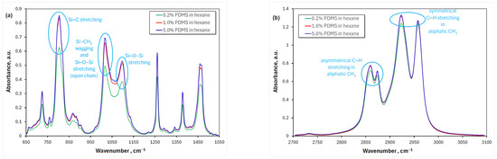
Figure 6.
The FTIR spectra of the fiberglass coated with PDMS for the range of the wavenumber: (a) 650–1550 cm−1; (b) 2700–3100 cm−1. Peaks related to characteristic chemical bonds in the PDMS were identified.
Moreover, the SEM images shown in Figure 7 confirm that although in some regions a polymer film attached to adjacent fibers, especially at fiber intersections, is visible, the majority of material pores are not blocked for 5.0%, which is the highest concentration used in experiments.
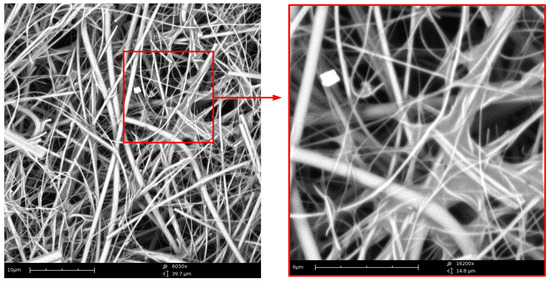
Figure 7.
The SEM images show layer I of fiberglass coated with PDMS from 5.0% solution at different magnifications (~6000× on the left, and ~16,000× on the right).
The results confirm the deposition of PDMS from the solution for all tested concentrations. The formation of the coating layer is due to the retaining of the solution in the pores of the filter material and its subsequent evaporation, which caused the formation of the polymer layer on the fibers. Hence, the amount of the PDMS indicated by the FTIR analysis and the contact angle measurement increases with an increase in polymer concentration in the solvent from 0.2% to 1.0%. However, when the concentration was elevated from 1.0% to 5.0%, the impact of the concentration increase was very small.
All afore-mentioned coatings were applied on the fiberglass media in the form of circular flat panels of the diameter 150 mm (the geometry suitable for the horizontal housing FH in Figure 3) and subject to experiments of the oil mist separation. As the reference for the effect of coating on the process, the experiment for the unmodified material was carried out. The results of the pressure drop and the efficiency versus time for the original material are presented in Figure 8. In this graph, the problem addressed in the research is easily noticeable at the end, when the filter media becomes saturated with the oil.
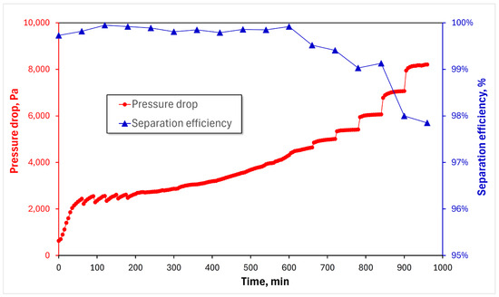
Figure 8.
The time-dependent profiles of the pressure drop and the separation efficiency for the unmodified filtration material.
The change in the pressure drop over time for the oleophilic unmodified material is shown in Figure 8. Characteristic variations of the dP were observed after the flow was interrupted and resumed. At the beginning, when not much liquid was held within the material, the monotonical increase of the pressure drop was not affected by the flow breaks. After that, when some amount of oil was accumulated in the material, a small decrease of the dP was visible (see Figure 8 between 60 and 180 min). However, when the saturation of the filter media approached the steady-state value (i.e., when a significant amount of oil was accumulated in the filter), each stoppage caused a significant step increase of the pressure drop. These different behaviors can be explained by the oil recombination driven by the capillary interaction. At low saturation, when the flow was interrupted, the oil was transported along the fibers so that it spread on their surface—the fibers became covered by oil film in a more uniform fashion, which created bigger passages for the flow of air. But when the saturation was high, much more oil from the downstream side of the filter was retracted back to the filter (imbibition caused by the capillary pressure), thus causing clogging of the porous media with the oil. Strong adhesion of oil to the fiber surface of the oleophilic material made it impossible to effectively push the liquid back to the outlet, hence the drift of the terminal value of the pressure drop was observed after each interrupting and resuming of the aerosol flow (see Figure 8—this issue started at time around 600 min, and above 720 min the increase was very high). Additionally, a decrease in separation efficiency was observed when the material became saturated with the oil. The reason for efficiency loss can be easily explained by analyzing the curve of fractional efficiency, which is presented in Figure 9.
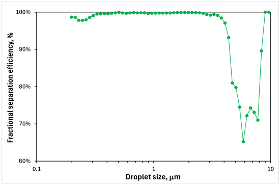
Figure 9.
The fractional efficiency for the unmodified filtration material at the end of the experiment (i.e., when the filter structure was saturated with the oil).
The fractional separation efficiency curve drops steeply for the size of droplets above 4 μm (see Figure 9). The collecting and coalescing of the droplets of this size from the inlet aerosol is probably performed with nearly 100% efficiency, similarly for droplets 1–2 μm, for which the collection mechanisms such as inertial impaction or interception are predominant. Thus, it can be deduced that the loss of efficiency for the droplets above 4 μm is not due to their penetration, but they are formed due to the redispersion on the outlet, where most of the oil is accumulated.
The comparison of the coalescence performance for the filter media coated using three commercial solutions from NanoX is presented in Figure 10. The differences between them are very pronounced. The EC1206 coalescing filter operates in a very similar way to unmodified material; however, the dP values are higher, and the upper limit of the dP sensor was exceeded after twelve hours. Moreover, the stepwise increase of the pressure drop caused by the flow interruption was not eliminated. This issue was significantly reduced for both oleophobic coatings, EC5028 and EC5029. In the case of material coated by the EC5029, a very fast increase of the pressure drop was observed, reaching the maximum measurable value in 5 h (see Figure 10). Although for this material the efficiency was the highest, the filter was blocked by the oil, which was probably kept on the upstream part of the filter. During the breaks of the system operation, an additional amount of oil was probably pushed out from the porous material driven by the capillary forces, which caused an additional increase in the dP. The filter modified using the EC5028 performed the best. The dP jumps were significantly reduced when the element was saturated with the oil. In addition, the efficiency did not decrease at the end of the test, which was observed for the unmodified material.
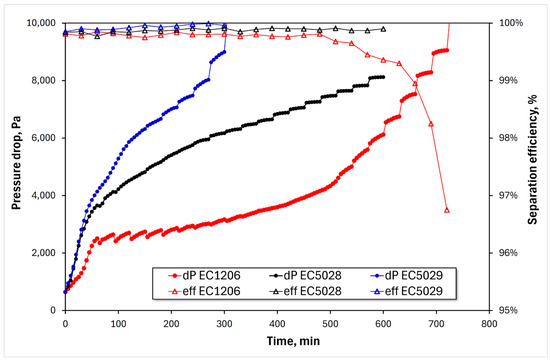
Figure 10.
Experimental results for the filters modified using commercial coatings from NanoX.
The results of the oil mist separation experiment for PDMS-coated media are presented in Figure 11. Very similar profiles of the pressure drop versus time were obtained for all three concentrations; however, the lowest terminal dP value and the smallest variations for the saturated element were observed for the modification carried out using the 0.2% concentration of the polymer in the hexane.
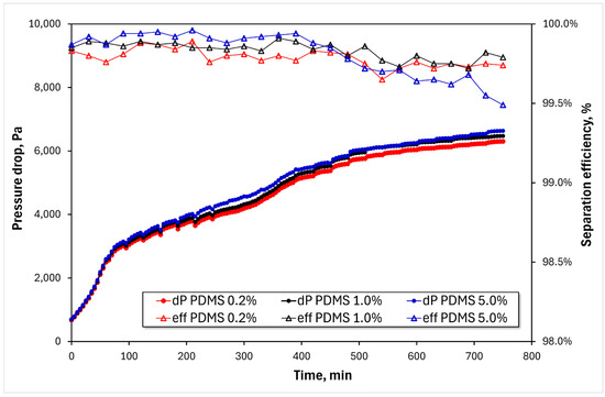
Figure 11.
Experimental results for the filters modified with the PDMS.
Based on the test results for flat media, the EC5028 and PDMS 0.2% modifications were selected for further testing in the form of the pleated cartridge filter. The selection criteria were as follows: a stable performance over a time of experiment and a minimal pressure drift when saturated. The additional layer of thickness ~3 mm made of polyester wrapped on the pleats was fitted on the outlet as a protection of the gas stream from re-entrainment.
Although the flow rate was recalculated to obtain the same superficial velocity through the filtration material, a different geometry and the presence of the afore-mentioned drain layer were responsible for the observed slightly higher values of the pressure drop for the pleated cartridge when compared to the flat material (Figure 9 and Figure 12). The presence of a drain layer helped to reduce the amount of re-entrained droplets in the unmodified element; however, this negative phenomenon was not fully eliminated (Figure 13). In the case of coalescer modified with the PDMS, no droplet carryover in the purified gas was observed, hence the separation efficiency of the saturated element was not reduced (this negative effect was not observed for the test of flat material either, where no drain layer was included). A pronounced difference in operation was obtained for the EC5028 modification on the pleated cartridge when compared to flat media. The separation efficiency was very high, but due to a different geometry, the material was more extensively blocked on the inlet with the oil accumulated between adjacent pleats. This is a possible reason why a fast increase of the dP above the 10 kPa was observed for the EC5028 coating on the cartridge filter (Figure 12).
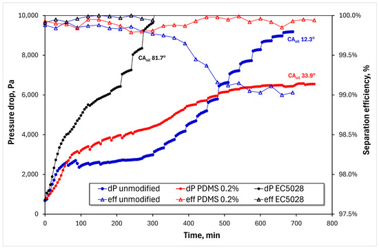
Figure 12.
Experimental results for the cartridge elements.
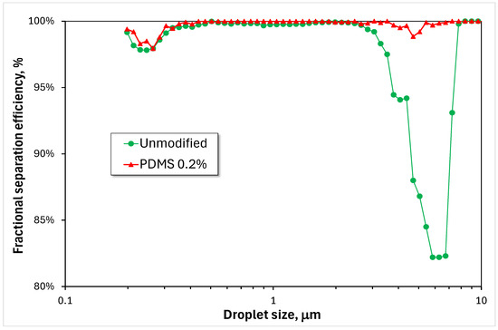
Figure 13.
Fractional efficiencies for unmodified and PDMS 0.2% cartridge elements.
The best-performing filtration material obtained for PDMS-coated fiberglass from a 0.2% solution was also verified in a much longer experimental program in which a single element was used five times. In this experiment, the filtration system operated continuously, i.e., no interruptions of the aerosol flow were applied. In the first test, the filter cartridge became saturated with the oil (reached a steady-state dP value), then the filtration system was put on hold for approximately 1 day, and after this time the aerosol flow was resumed. For the element saturated with the oil, the pressure drop stabilized very quickly, thus the system operation time was set to 3 h. This procedure, i.e., 3 h of system operation and approximately 21 h of downtime, was applied for the next 4 days. The results are presented in Table 2.
Table 2.
Performance of the PDMS 0.2% filter within 5 consecutive days of testing.
A relatively long-time operation using the same element multiple times confirmed that the performance parameters of the coalescing filter were maintained. These results confirm the stability of the applied coating in contact with the test oil and at the process conditions used in the tests. The presence of PDMS after the process was also confirmed using the SEM and FTIR of the material used for 5 days, which was washed with the IPA before analysis. However, these techniques provided qualitative information only—the PDMS was still present on the fibers.
An interpretation of observed phenomena on the performance of coalescing filters with modified surface properties can be determined based on the principles of the film-channel model. This model constitutes a reliable theoretical approach, which allows for understanding the principles of the process and clarifies different saturation profiles across the media made of material, which differ in the wettability. The model assumptions were confirmed in numerous research studies; therefore, it accounts for well-established knowledge regarding the operation of coalescence filters. It can also be useful to explain observed phenomena in this research. The unmodified material used in this work is strongly oleophilic, so according to the model assumptions regarding the oil distribution at steady-state operation, the oil film is created on the downstream side of the filter (Figure 14). When the flow is interrupted and the drag force acting upon the liquid disappears, the oil collected on the outlet side of the filter can flow backward into the porous material driven by capillary forces. As a result, the filter is loaded with an extra amount of oil, which causes the increase in pressure drop when the flow is resumed. Although it seems that the process should be reversible and the steady-state dP value (neglecting the dP creep) could be regained, it was not observed in the studied system (i.e., material and oil properties, and the flow rate applied). This was probably due to a very strong adhesion of the oil to the fibers, which counteracted the dislocation of oil inside the fibrous material. A new configuration of oil inside the porous material was probably created, conducive to blocking the material (e.g., filling the pores or creating the oil “sails” between the fibers), which translated into a higher pressure drop after the restart.
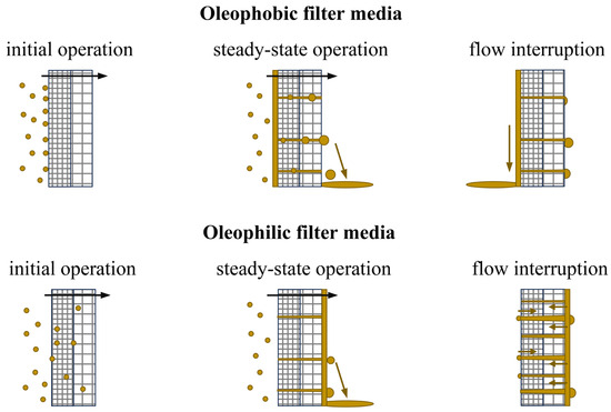
Figure 14.
Schematic interpretation of the origin of the observed problem based on principles of the film-channel model.
It seems that the performance of oleophobic material should be much better in terms of self-cleaning of the filter on the upstream side of the filter where the oil film is created, as shown schematically in Figure 14. However, if the capillary forces acting on the oil so that they confine it to entering the liquid into porous material are too high, it can lead to a massive accumulation of the oil on the inlet and filter blockage. This effect was observed for highly oleophobic modifications obtained by coating with the commercial products EC5028 and EC5029 (Figure 10). The measurements of the contact angle with oil (Figure 4) confirm this hypothesis. For these coatings, the increase in pressure drop was very fast, so that it exceeded the range of the dP sensor before the steady-state value was reached.
To conclude, the best results obtained for the fiberglass media dip-coated using 0.2% PDMS solution in hexane provide a good balance between minimizing the so-called “jump dP” related to the passage of air through the film and blocking the material pores by the liquid at the filter inlet and the reduction of capillary-driven reverse flow when the filtration system is down (Figure 11). As shown in Figure 4, it is characterized by a moderate wettability with the oil (i.e., a reduced oleophilicity compared to the native material). It was also confirmed that the PDMS coating layer on the material surface is robust at the conditions used in the research—it was not washed out in contact with the oil nor mechanically damaged due to shear stresses during the operation.
5. Summary
In this work, the experimentally observed problem of increases in pressure drop on coalescing filters applied for oil mist removal is presented. The mechanism responsible for this adverse effect has been identified, pointing out the capillary transport during downtime and liquid reconfiguration in the porous nonwoven structure of the filter as the main cause. Research was carried out on the modification of the surface properties of oleophilic glass fiber structures to minimize the filter blocking phenomenon that occurs during a break in the operation of the oil mist air filtering unit. The most effective solution among the tested coatings that changed the affinity of oil to the filter material turned out to be PDMS layers deposited using the dip-coating method, obtained by immersion of the material in the polymer solution in hexane. The glass surface modified in this way was characterized by moderate values of the static contact angle with the oil, which were higher compared to the material without modification (increase in the contact angle with oil from approximately 12° to 34°). Although the change in material affinity to the oil indicated by the value of the contact angle was not very pronounced, a massive effect on the separation performance was observed. The coating also turned out to be stable in contact with the oil and in high-shear flow conditions, which was verified by various techniques (CA measurement, FTIR, and SEM). The robustness of the PDMS layer was also confirmed in experiments in which a single cartridge element was used five times (nearly a day of installation downtime between experiments)—the operation performance was maintained. The simplicity of producing the coating, its stability, and the low consumption of chemical reagents make it feasible and economically viable to consider the proposed modification method in real applications.
Author Contributions
Conceptualization, A.K.; Methodology, A.K.; Investigation, A.K., S.K. and M.S.; Writing—original draft, A.K.; Supervision, A.K. All authors have read and agreed to the published version of the manuscript.
Funding
This research was funded by Polish National Centre for Research and Development, grant no. TECHMATSTRATEG-III/0005/2019-00 (the industrial partner in this project is Amazon Filters).
Institutional Review Board Statement
Not applicable.
Informed Consent Statement
Not applicable.
Data Availability Statement
Data is contained within the article.
Conflicts of Interest
The authors declare no conflict of interest.
References
- Mead-Hunter, R.; King, A.J.C.; Mullins, B.J. Aerosol-mist coalescing filters—A review. Sep. Purif. Technol. 2014, 133, 484–506. [Google Scholar] [CrossRef]
- Krasiński, A.; Sołtan, Ł.; Kacprzyńska-Gołacka, J. Effect of fiber surface modifications on the coalescence performance of polybutylene terephthalate filter media applied for the water removal from the diesel fuel. Sep. Purif. Technol. 2020, 236, 116254. [Google Scholar] [CrossRef]
- Krasiński, A.; Wierzba, P. Removal of emulsified water from diesel fuel using polypropylene fibrous media modified by ionization during meltblow process. Sep. Sci. Technol. 2015, 50, 1541–1547. [Google Scholar] [CrossRef]
- Agarval, S.; Von Arnim, V.; Stegmaier, T.; Planck, H.; Agarwal, A. Role of surface wettability and roughness in emulsion separation. Sep. Purif. Technol. 2013, 107, 19–25. [Google Scholar] [CrossRef]
- Kampa, D.; Wurster, S.; Buzengeiger, J.; Meyer, J.; Kasper, G. Pressure drop and liquid transport through coalescence filter media used for oil mist filtration. Int. J. Multiph. Flow 2014, 58, 313–324. [Google Scholar] [CrossRef]
- Kampa, D.; Wurster, S.; Meyer, J.; Kasper, G. Validation of a new phenomenological “jump-and-channel” model for the wet pressure drop of oil mist filters. Chem. Eng. Sci. 2015, 122, 150–160. [Google Scholar] [CrossRef]
- Gac, J.M.; Gradoń, L. Analytical investigation and numerical modeling of collisions between a droplet and a fiber. J. Colloid Interface Sci. 2012, 369, 419–425. [Google Scholar] [CrossRef]
- Chang, C.; Ji, Z.; Liu, J. The effect of a drainage layer on filtration performance of coalescing filters. Sep. Purif. Technol. 2016, 170, 370–376. [Google Scholar] [CrossRef]
- Chang, C.; Ji, Z.; Liu, J. The effect of a drainage layer on the saturation of coalescing filters in the filtration process. Chem. Eng. Sci. 2017, 160, 354–361. [Google Scholar] [CrossRef]
- Chang, C.; Ji, Z.; Liu, J. Pressure drop and saturation of non-wettable coalescing filters at different loading rates. AIChE J. 2018, 64, 180–185. [Google Scholar] [CrossRef]
- Chang, C.; Ji, Z.; Liu, J. The effect of a drainage layer on saturation and liquid distribution of oleophobic coalescence filters. Sep. Purif. Technol. 2018, 194, 355–361. [Google Scholar] [CrossRef]
- Mullins, B.J.; Pfrang, A.; Braddock, R.D.; Schimmel, T.; Kasper, G. Detachment of liquid droplets from fibres—Experimental and theoretical evaluation of detachment force due to interfacial tension effects. J. Colloid Interface Sci. 2007, 312, 333–340. [Google Scholar] [CrossRef] [PubMed]
- Hotz, C.J.; Mead-Hunter, R.; Becker, T.; King, A.J.C.; Wurster, S.; Kasper, G.; Mullins, B.J. Detachment of droplets from cylinders in flow using an experimental analogue. J. Fluid Mech. 2015, 771, 327–340. [Google Scholar] [CrossRef]
- Chen, F.; Ji, Z.; Qi, Q. Effect of surface wettability on filtration performance of gas-liquid coalescing filters. Powder Technol. 2019, 357, 377–386. [Google Scholar] [CrossRef]
- Chen, F.; Ji, Z.L.; Qi, Q.Q. Effect of pore size and layers on filtration performance of coalescing filters with different wettabilities. Sep. Purif. Technol. 2018, 201, 71–78. [Google Scholar] [CrossRef]
- Chen, F.; Yu, W.; Ji, Z.; Lin, G.; Ding, H.; Pi, L.; Wu, X. Development and coalescence mechanism of an improved filter cartridge for oil mist separators. Chem. Eng. Res. Des. 2022, 187, 306–318. [Google Scholar] [CrossRef]
- Mullins, B.J.; Mead-Hunter, R.; Pitta, R.N.; Kasper, G.; Heikamp, W. Comparative performance of philic and phobic oil-mist filters. AICHE J. 2014, 60, 2976–2984. [Google Scholar] [CrossRef]
- Wu, Y.; Manzo, G.M.; Chase, G.G. Thickness shrinkage of microfiber media in gas–liquid coalescence filtration. Sep. Purif. Technol. 2015, 141, 188–196. [Google Scholar] [CrossRef]
- Azarafza, A.; King, A.J.C.; Mead-Hunter, R.; Schuler, J.; Abishek, S.; Mullins, B.J. The influence of layer separation on multilayer mist coalescing filter performance. Sep. Purif. Technol. 2021, 273, 118752. [Google Scholar] [CrossRef]
- Bredin, A.; Mullins, B.J. Influence of flow-interruption on filter performance during the filtration of liquid aerosols by fibrous filters. Sep. Purif. Technol. 2012, 90, 53–63. [Google Scholar] [CrossRef][Green Version]
- Kolb, H.E.; Kasper, G. Mist filters: How steady is their “steady state”? Chem. Eng. Sci. 2019, 204, 118–127. [Google Scholar] [CrossRef]


Disclaimer/Publisher’s Note: The statements, opinions and data contained in all publications are solely those of the individual author(s) and contributor(s) and not of MDPI and/or the editor(s). MDPI and/or the editor(s) disclaim responsibility for any injury to people or property resulting from any ideas, methods, instructions or products referred to in the content. |
© 2024 by the authors. Licensee MDPI, Basel, Switzerland. This article is an open access article distributed under the terms and conditions of the Creative Commons Attribution (CC BY) license (https://creativecommons.org/licenses/by/4.0/).