Article

Sustainable Diamond Burnishing of Chromium–Nickel Austenitic Stainless Steels: Effects on Surface Integrity and Fatigue Limit

1
Department of Material Science and Mechanics of Materials, Technical University of Gabrovo, 5300 Gabrovo, Bulgaria
2
Department of Mechanical Engineering Equipment and Technologies, Technical University of Gabrovo, 5300 Gabrovo, Bulgaria
3
Department of Material Sciences, Technical University of Varna, 9010 Varna, Bulgaria
*
Author to whom correspondence should be addressed.
Appl. Sci. 2024, 14(19), 9031; https://doi.org/10.3390/app14199031 (registering DOI)
Submission received: 31 August 2024 / Revised: 25 September 2024 / Accepted: 3 October 2024 / Published: 6 October 2024
(This article belongs to the Special Issue Advances in Machining Process for Hard and Brittle Materials)

Abstract

:
This study aims to evaluate the influence of lubrication and cooling conditions in the diamond burnishing (DB) process on the surface integrity and fatigue limit of chromium–nickel austenitic stainless steels (CNASSs) and, on this basis, identify a cost-effective and sustainable DB process. Evidence was presented that DB of CNASS performed without lubricating cooling liquid satisfies the requirements for a sustainable process: the three key sustainability dimensions (environmental, economic, and social) are satisfied, and the cost/quality ratio is favorable. DB was implemented with the same values of the main governing factors; however, four different lubrication and cooling conditions were applied: (1) flood lubrication (process F); (2) dry without cooling (process D); (3) dry with air cooling at a temperature of −19 °C (process A); and (4) dry with nitrogen cooling at a temperature of −31 °C (process N). Conditions A and N were realized via a device based on the principle of vortex tubes. All four DB processes provide mirror-finished surfaces with Ra roughness parameter values from 0.041 to 0.049 μm, zones with residual compressive stresses deeper than 0.5 mm, and increases in the specimens’ fatigue limit (as determined by the accelerated Locati’s method) compared to turning and polishing. Processes F and D produce the highest microhardness on the surface and at depth. The process D introduces maximum compressive residual axial and hoop stresses in the surface layer. The dry DB processes (D, A, and N) form a submicrocrystalline structure with high atomic density, which is most strongly developed under process D. When high fatigue strength is required, DB with air cooling should be chosen, as it provides a more favorable cost/quality ratio, whereas dry DB without cooling is the most suitable choice for applications that require increased wear resistance.

1. Introduction

Chromium–nickel austenitic stainless steels (CNASSs) are the most common class of stainless steels. CNASSs are used in many industrial applications due to their superior corrosion resistance, excellent formability, good machinability, and weldability. However, a key disadvantage of these steels is their poor strength and hardness, which, due to their austenitic structure, cannot be increased by the application of heat treatment. Heating the specimen to 1100 °C, holding it at this temperature to dissolve the carbides, and subsequently rapidly cooling the specimen in water results in a larger-grained alloyed austenite structure. Accordingly, the sample’s strength decreases, while its plasticity and corrosion resistance both increase [1]. A slight improvement in hardness, static strength, and fatigue strength (under steady-state loading) of AISI 302 steel can be achieved by deep cryogenic treatment [2,3]. However, these mechanical characteristics may drastically increase in response to cold plastic deformation due to the strain-hardening effect, which can be either volumetric [4,5] or surface [6,7,8], i.e., surface cold working (SCW). Besides strain hardening, cold working also leads to the γ α phase transformation, forming so-called strain-induced α -martensite, which increases the strength and hardness of the specimen but worsens its corrosion resistance [1].
SCW is a surface engineering approach to modify the surface layers of metal components through mass conservation. Static and dynamic SCW methods increase the surface microhardness and introduce compressive residual stresses in the surface and subsurface layers of the sample. In addition, static SCW methods, known as burnishing methods, drastically reduce the specimen’s roughness height parameters, which may produce mirror-finished surfaces.
One of the static SCW methods is diamond burnishing (DB) [9], which is implemented on conventional machine tools and those with computer numerical control (CNC) and forms part of the technological process used to produce rotary details and less often those with flat surfaces. The interface between the deforming diamond insert and the treated surface is characterized by sliding friction. Due to the heat generated, mostly from friction, the DB process is usually implemented with lubrication under cooling conditions. Since DB is a finishing process, i.e., realized after machining on the same machine tool (turning, milling, drilling, and, in some cases, grinding), the environmental and human impacts of using lubricating cooling liquid (LCL) during cutting [10] are also relevant for DB when it is performed in the presence of LCL. Conventionally, DB is usually implemented under flood lubrication conditions, which involve the use of extensive LCL.
The purpose of LCL in cutting and burnishing processes is to reduce the heat generated by friction and plastic deformation, wash chips from the cutting area, and inhibit corrosion, with the aim of improving the quality of the machined surface, reducing tool wear, and increasing productivity [11]. However, the widespread usage of LCL (with over two billion gallons of cutting fluids used by North American manufacturers alone in 2002 [11]) can cause economic, ecological, and human health problems. LCL costs typically range between 7 and 17% of total production costs [12,13] and may increase by a further 20% for difficult-to-cut alloys [14]. The cost of recycling spent LCL is two to four times that of buying new LCL [15]. In addition, disposal of purified LCL can contaminate natural resources including rivers, lakes, air, and groundwater [11]. LCL can harm human health, causing skin infections, pneumonia, and lung cancer [16,17,18,19,20]. LCLs also commonly generate a mist in the air that can cause respiratory diseases and several types of cancer [21]. Various approaches have been developed to control LCL mist, including kinematic coagulation, innovative machine tool design, and dry machining [21]. Alternatively, environmental technologies such as minimum quantity lubrication (MQL) [22], cryogenic machining [23], and dry cutting [12] can be used to reduce or eliminate LCL.
Addressing the problems associated with LCL usage and its harmful impacts on the environment and human health represents a vital step in achieving a sustainable manufacturing process. Sustainable manufacturing evolved from the concept of sustainable development, which was introduced in the 1980s in response to growing concerns about the impact of human progress on the environment [24]. At the core of the sustainability concept is long-term human well-being, which is strongly linked to the environment. To achieve sustainability, the three key dimensions—environmental, economic, and social—must be considered simultaneously and in relation to each other. In this context, the development of sustainable manufacturing processes is an important approach through which environmental harm can be minimized. While several definitions of sustainable manufacturing processes exist, they share the common themes of simultaneously minimizing negative environmental impacts, saving energy and natural resources, ensuring safety for employees and consumers, and ensuring sound economic justification. Thus, for a given process to be truly sustainable, it must simultaneously be economically, environmentally, and socially sustainable. For instance, machining technologies using MQL partially reduce pollution and minimize lubrication costs but do not improve working conditions (i.e., the social dimension). Developing sustainable manufacturing processes is particularly important in finishing (including burnishing) processes, as these processes ensure the quality of the manufactured components, which will in turn determine the life cycle. Efforts to develop a sustainable and cost-effective manufacturing finishing process will yield a synergistic effect due to the resulting improvement in the cost/quality ratio. In the present article, these concepts are explored in the context of the DB process for CNASS.
Burnishing processes are typically performed under lubricating and cooling conditions, most often via the flood lubrication approach. The use of lubrication reduces the friction between the deforming element and the treated surface; however, greater frictional forces imply greater tangential stresses and, accordingly, a finer resulting structure [25]. The use of LCL in burnishing is inherently not environmentally friendly; however, slide burnishing (and DB in particular) generates heat and cooling is necessary in some cases. Replacing traditional flood lubrication with alternative approaches for lubrication and cooling in burnishing processes is an important step toward realizing sustainability [23]. Some alternative approaches include MQL, cryogenic conditions, and dry machining and burnishing. Given the wide variety of materials and burnishing conditions available, process optimization aimed at realizing a sustainable burnishing process is fully possible.
The effect of applying the MQL approach to the DB process in terms of surface integrity (SI) characteristics has been widely studied [26,27,28,29,30,31]. However, as noted above, the MQL technique partially reduces pollution and lubrication costs but does not address the social sustainability component of using LCL. As an alternative, implementing traditional machining (i.e., turning, milling, drilling, and grinding) and burnishing processes under unlubricated cryogenic conditions can help achieve a sustainable process [23]. The cryogenic temperature range is below −180 °C [23], with liquid nitrogen most commonly used as a refrigerant. Chronologically, cryogenic machining (first introduced by K. Uehara and S. Kumagai in 1968 [32]) precedes cryogenic burnishing. Detailed information on cryogenic-assisted burnishing (including DB) is contained in a review paper [33]. A notable disadvantage of using cryogenic conditions is the costs associated with specialist equipment installation, which can also occupy a large space. In addition, working with liquid nitrogen or liquid helium poses potential human health risks.
Dry machining and dry burnishing can, in some cases, be a viable alternative to traditional flood lubrication treatment. Due to the accessibility of the cutting area, turning and milling represent excellent opportunities for eliminating cutting fluids [34]. This is also true for static burnishing processes, as their kinematic schemes are similar to those of turning. However, there are relatively few studies to date [27,29,30,31,35,36] on the effects of dry DB on the SI characteristics and operational behavior of machined metal components, and among these, only [36] describes CNASS. Another potential compromise option for realizing dry DB while reducing heat generation is to use a vortex tube [37,38] to supply cold air to the plastic deformation zone; however, no studies to date have investigated this aspect in the context of CNASS.
The effects of DB on the SI and operating behavior of CNASS components are studied in [1,6,36,39,40,41,42,43,44,45,46,47,48,49]. The most commonly studied grade of CNASS is 316 [36,41,42,43,44], followed by 304 [1,6,39,40], 317 [45,46,47], and 321 [48,49]. Most studies to date have explored simple correlations between DB governing factors and SI characteristics [1,6,36,39,40,42,43,44,45,48,49]; however, significantly less research has investigated the correlation between DB governing factors and operating behavior in terms of corrosion resistance [1], wear [42,45], and fatigue behavior [1,6,42]. Explicit correlations between the surface integrity and fatigue limit of diamond-burnished CNASS were obtained in [50]. In particular, there have been no comprehensive studies on the influence of lubrication and cooling conditions in the DB process on the SI and fatigue behavior of CNASS components. To address these limitations, the present study aims to evaluate the influence of lubrication and cooling conditions in the DB process on the SI and fatigue limit of CNASS and, on this basis, identify a cost-effective and sustainable DB process.

2. Materials and Methods

2.1. Material Identification

The material used in this study was AISI 316 CNASS in the form of hot-rolled bars with a diameter of 30 mm, which were used in an as-received state. The chemical composition of the study material was established via optical emission spectrometry. Tensile tests at room temperature were conducted using a Zwick/Roell Vibrophore 100 testing machine (Ulm, Germany). The main mechanical characteristics were established based on the arithmetic mean of three specimens [51] (Figure 1a). The hardness was measured using a VEB-WPM tester (Germany) with a spherical-ended indenter with a diameter of 2.5 mm, load of 63 kg, and holding time of 10 s.

2.2. DB Implementation and Designations of the Specimens

DB (Figure 2) was implemented on an Index Traub CNC lathe (Germany). The main governing factors in this process are the radius r of the spherical-ended diamond insert, the burnishing force F b , the feed rate f , and the burnishing velocity. In this study, the smoothing DB process [1,6] was implemented. The governing factor values were obtained from [6] and are listed in Table 1. A special burnishing device mounted on the tool post of the lathe was used. The required burnishing force was set by deforming a linear axial spring located in the device. The necessary burnishing force magnitude was defined in advance via the screw-nut mechanism based on the spring’s characteristic. The deforming diamond insert was then brought into contact with the specimen at its centerline and normal to the surface being treated. The device was fed a further 0.05 mm into the specimen to allow the diamond insert to become disengaged from the stop in the device; thus, an elastic contact between the diamond insert and the surface being burnished was achieved.
The DB process was implemented under the following four lubrication and cooling configurations: (1) conventional flood lubrication with Vasco 6000 lubricant; (2) cold air cooling without lubrication using a special device (Emuge-Franken, Germany) with a cold air nozzle based on the principle of vortex tubes; (3) nitrogen-assisted cooling without lubrication using the same device but with nitrogen from a pressure bottle instead of air; and (4) dry conditions without cooling. In the second and third cooling configurations, the following temperatures were measured on the surface of the nozzle using a thermocouple located as close as possible to the contact zone between the diamond insert and the treated specimen: −19 °C and −31 °C, respectively. The thermocouple was K-type with a range of −40 °C to +100 °C. The signal from it entered a portable device for measuring temperature through thermocouples.
In all the performed tests, the diamond-burnished specimens were denoted as follows: F (flood lubrication), A (air cooling), N (nitrogen cooling), and D (dry without cooling). The same notations are used throughout to indicate the corresponding DB processes.

2.3. SI Characteristics
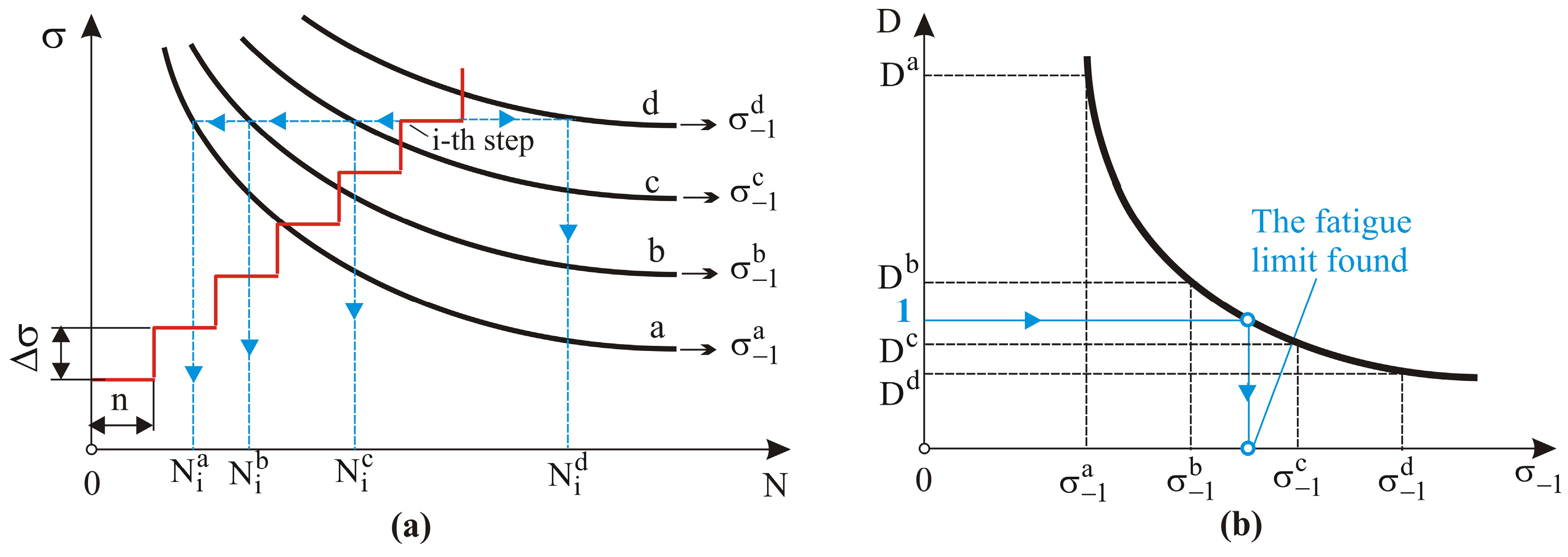
Cylindrical specimens of dimensions ϕ 28 × 40   m m were used to determine the SI characteristics of the material. The 2D roughness parameters were measured using a Mitutoyo Surftest SJ-210 surface roughness tester on six equally spaced sample generatrixes. A base length of 0.8 mm was chosen. For each generatrix, the measurement results were obtained as average values of five base lengths. The final values of 2D roughness parameters were calculated as the arithmetic average values from the measurements on the six sample generatrixes. One sample was used to measure the roughness parameters.
A ZHVµ Zwick/Roell microhardness tester (Ulm, Germany) was used to determine the microhardness at the surface (0.05 kgf loading) and on a profile at depth (0.01 kgf loading). A holding time of 10 s was used. The final surface microhardness value was calculated as the center of clustering of 10 measurements.
To determine the percentage content of strain-induced martensite relative to austenite in the surface layer, a Bruker D8 Advance diffractometer (Billerica, MA, USA) and Bruker DIFFRAC.Dquant V1.5 software [52] were used. The characteristics of the residual stress X-ray measurements are shown in Table 2. The specimens′ microstructures were observed via scanning electron microscopy (SEM; Zeiss Evo 10, Germany).

2.4. Fatigue Tests

Figure 1b shows the geometry of the fatigue specimen [53]. The fatigue tests were conducted on a UBM rotary bending testing machine (Walter + Bai AG, Switzerland) with a loading frequency of 50 Hz in air. Locati′s accelerated method was used to determine the fatigue limits. This method is based on the Palmgren–Miner linear damage hypothesis, which is a specific case of a general cumulative damage theory [54]. To determine the fatigue limit of a material, this method requires only one specimen, which is then subjected to a stepwise increasing load (Figure 3a). The difference Δ σ of the stress amplitudes between any two adjacent levels and the number of cycles n for each step are constant quantities. The load is increased until the test specimen fails. To calculate the fatigue limit, a minimum of three assumed S-N curves must be selected for the given material. The difference Δ σ 1 between the fatigue limits of two adjacent S-N curves is a constant value, and the curves are equidistant. According to the linear hypothesis, failure occurs when the sum of accumulated damages D is equal to unity:
D = i = 1 k n i / N i = 1
where k is the number of steps, and Ni is the number of cycles required for failure to occur during the i t h load step for the corresponding S-N curve.
For each of the selected fatigue curves, the sum of the accumulated damage D is calculated. The obtained values are plotted in the “fatigue limit–sum of accumulated damage D” coordinate system. The stress obtained by interpolating for D = 1 in the “fatigue limit–damage” curve is the target fatigue limit for the studied material (Figure 3b).
In this study, three specimens were used for each material condition (i.e., three for each finishing technique). The fatigue limit was calculated as the arithmetic mean of the three specimens for each material condition.
Five groups of specimens (each containing three samples) were used. The first group was treated by turning and polishing and was used as a reference condition (RC). The purpose of polishing after turning is to satisfy the requirements of the standard [53] in terms of the surface roughness parameter Ra (see Figure 1b). The remaining four groups were treated by DB under flood lubrication (F), air cooling (A), nitrogen cooling (N), and dry without cooling (D) conditions. The DB processes were performed after turning without polishing.

3. Results and Discussion

3.1. Material Measurements

The chemical composition of the used AISI 316 CNASS is shown in Table 3. The minor chemical elements (constituting the rest of the specimen up to 100 wt%) are Al, Pb, Sn, B, Zr, Se, and Sb. The main mechanical characteristics of this material are shown in Table 4.

3.2. SI Characteristics

3.2.1. Microstructures
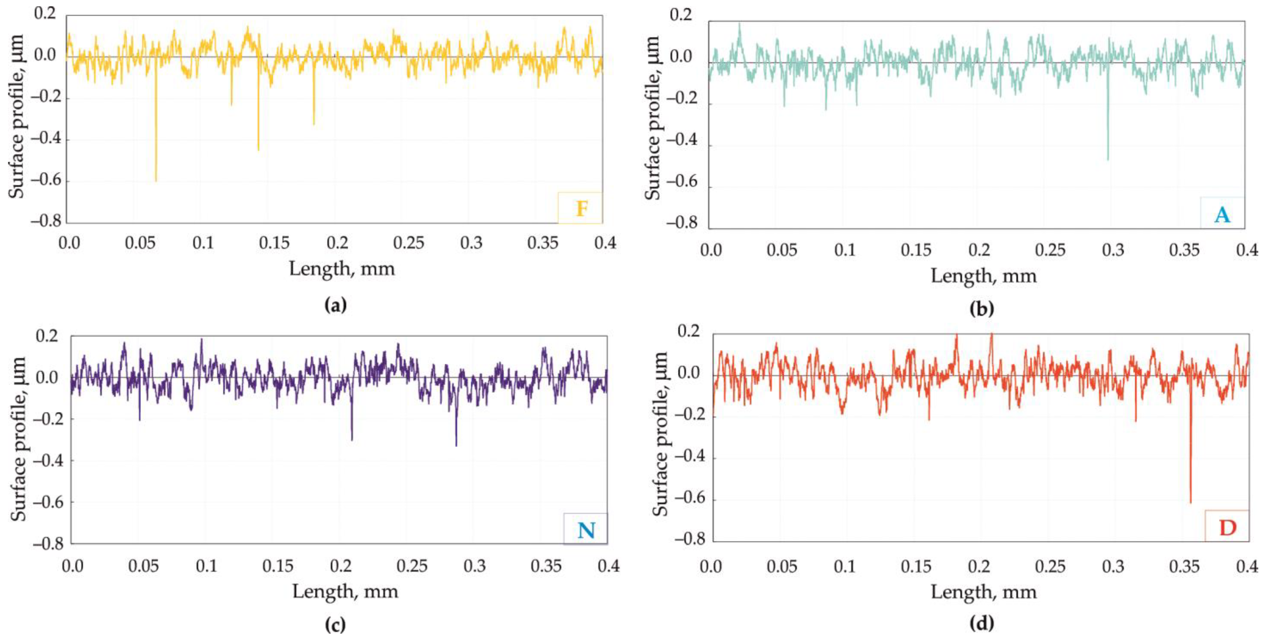
As noted above, the four studied DB processes used the same governing factor values (i.e., diamond insert radius, burnishing force, feed rate, and burnishing velocity) but were performed under different lubrication and cooling conditions. This approach allowed the influence of different burnishing conditions on the microstructure of the material’s surface and subsurface layers to be explored.
The different DB process configurations result in varying temperatures and degrees of plastic deformation, which are caused by the different friction and cooling conditions. The temperature primarily depends on the amount of heat generated in the plastic deformation process (mostly due to the sliding friction) and is less strongly related to the cooling conditions [55]. In addition, the degree of plastic deformation also depends on the type of normal contact (i.e., elastic or hard) between the deforming diamond and the machined surface, which is defined by the configuration of the burnishing device. The device we used (Figure 2) provides an elastic normal contact; therefore, the depth of penetration is not constant and varies within a narrow range.
The microstructures observed in the surface and subsurface layers in a cross-section of specimens processed by DB under different conditions are shown in Figure 4. The depths of the affected layers resulting from the four DB processes are practically the same (approximately 7 μm). However, these layers differ from each other in a qualitative aspect. Plastic deformation within the surface layer increases the dislocation density toward grain boundaries and reorients grains that were initially unfavorably oriented with respect to the flow direction. The plastic deformation mechanism of CNASS is characterized by slip lines and twin formation [56]. In the strain-hardening process, coherent twin boundaries and microstrips of twin structures are formed in the grains. With increasing plastic deformation, deformation bands are formed from groups of grains. As a consequence of the sliding friction contact in the DB process, in the contact zone, the orientation of the microstrip in the grain deviates in the direction of the relative movement of the deforming diamond. This mechanism is primarily characteristic of the microstructure obtained under the flood lubrication condition (Figure 4b). This configuration maintains a relatively lower temperature during the burnishing process (in part due to the reduced friction), which minimizes the substructural changes in the areas with microstrips.
The microstructures observed in the remaining samples (Figure 4a,c,d) were formed under dry sliding friction conditions with different cooling techniques. These samples exhibit substructural changes in the microstrip between individual twins (i.e., slip lines). Specimen D (Figure 4a) is diamond-burnished without cooling; accordingly, the deformation process took place at the highest temperature. Under these conditions, the polygonization temperature of the treated steel is reached faster. The plastic deformation at higher temperatures favors fragmentation between the individual slip lines forming the microstrip. In these zones, a submicrocrystalline structure with high atomic density is formed. This structure is characterized by increased microstrip density and, accordingly, by increased second-order microstresses. The structural changes described here are the most pronounced in sample D (Figure 4a), in which the microstrips in the grains are partially obliterated (i.e., the slip lines are not clearly distinguished). Substructural fragmentation down to a nanocrystalline level is believed to lead to improved mechanical behavior in burnished CNASS [56]. The effect of substructural fragmentation was observed to a lesser extent in specimen A (air cooling) (Figure 4c) and the least in specimen N (nitrogen cooling) (Figure 4d); thus, this effect decreases with decreasing temperature.

3.2.2. Roughness

The average value of the Ra roughness parameter obtained via turning (i.e., before burnishing) was 0.471 μm. The specimens′ 2D roughness height, shape, and Rk group parameters obtained in different DB configurations are listed in Table 5. Figure 5 shows a comparison of the respective roughness profiles, while Figure 6 shows a comparison of the most common Ra values. The four DB processes significantly reduce the height roughness parameters compared to turning, resulting in mirror-like surfaces. The Ra parameter is reduced between 9.6 and 11.5 times, with a difference of 8 nm between the maximum and minimum Ra values. The DB processes produce surface textures with negative skewness (Rsk) and kurtosis (Rku) values greater than three. The Rsk and Rku parameters directly influence the operational behavior of the corresponding component [57,58]. More negative skewness values and kurtosis values greater than 3 are interpreted to improve a specimen’s tribological behavior, especially in the boundary friction and lubrication friction regimes [46,59]. From this perspective, the dry DB process (specimen D) produces a suitable surface texture. The better oil-holding capacity of specimen D is also confirmed by the largest value of the functional parameter Rvk (see Table 5) [57].

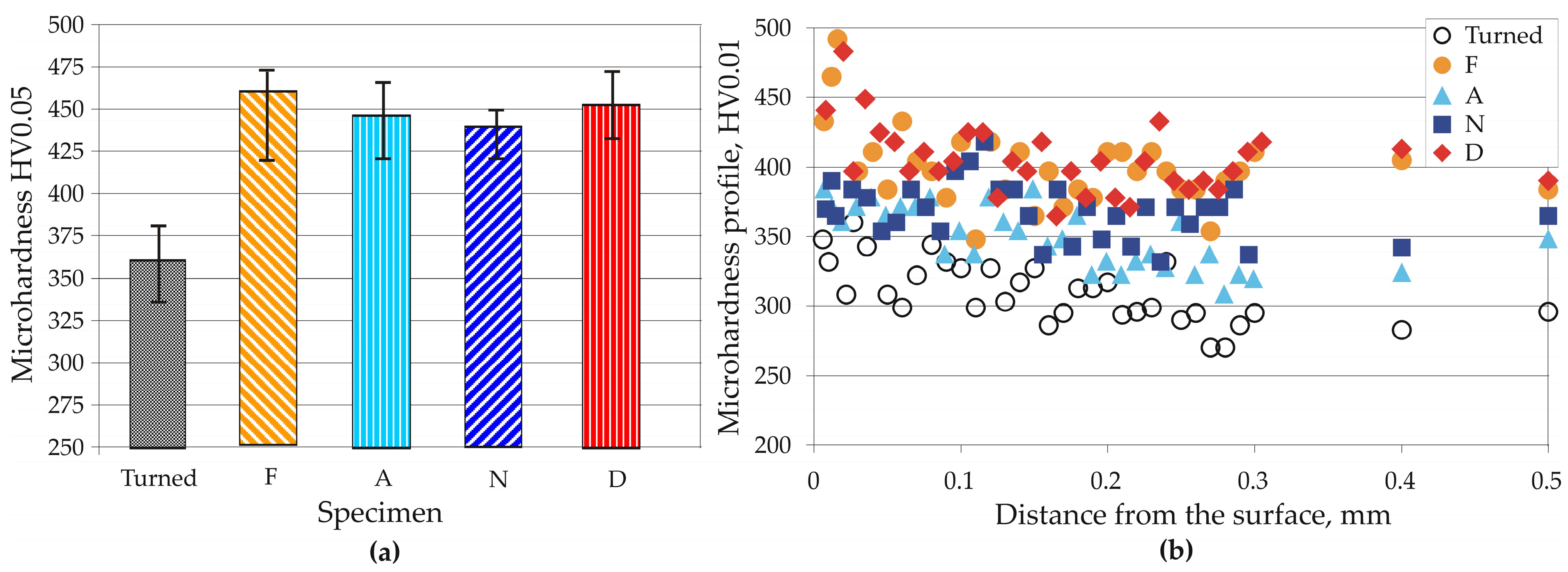
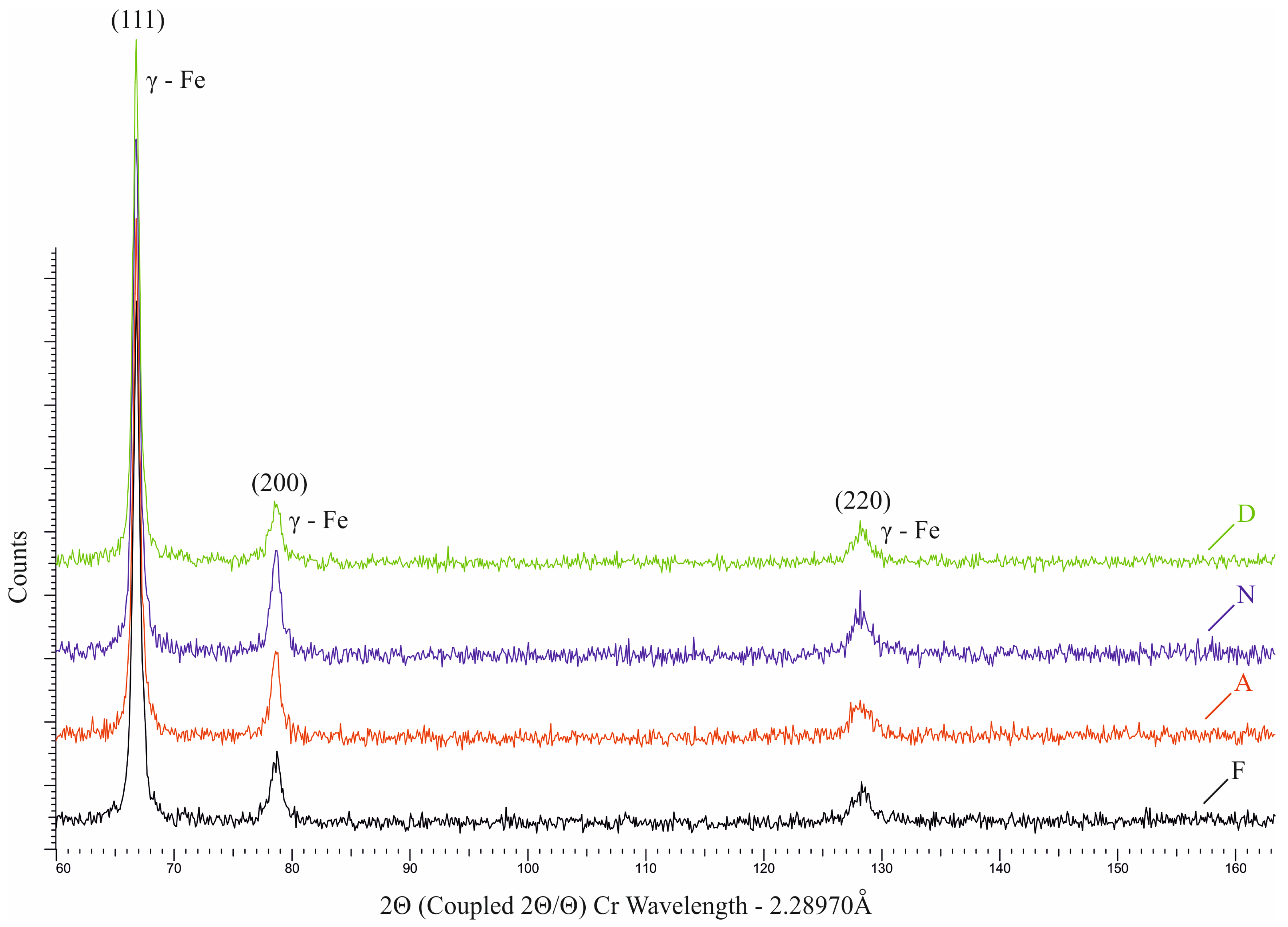
3.2.3. Microhardness and Phase Analysis Results

The surface microhardness values obtained from different DB processes are shown in Figure 7a. All the DB processes significantly increase the surface microhardness, with the maximum nominal value achieved under flood lubrication (specimen F). The lowest nominal surface microhardness value was obtained for sample N (dry DB with nitrogen cooling). Notably, all four nominal values fall within a narrow range from 440 (specimen N) to 459 HV (specimen F).
The microhardness distributions versus depth from the surface obtained in different DB configurations are plotted in Figure 7b. The measurements were performed on polished cross-sections. The highest microhardness at depth was obtained when DB was performed either under flood lubrication (specimen F) or under dry conditions without cooling (specimen D). Under these two conditions, the highest surface microhardness values were also obtained (see Figure 7a). Due to the absence of lubrication and cooling the highest temperature in the diamond-burnished surface contact zone can assumed to occur in sample D, followed sequentially by samples F, A, and N, as the LCL temperature is significantly higher than that of the air (−19 °C) and nitrogen (−31 °C) used for cooling in this process. Given the selected burnishing device with elastic normal contact used in this experiment and also the temperature in the contact area, the same sequence can also be assumed for the depth of penetration, i.e., greatest in sample D, followed by samples F, A, and N, due to the so-called softening effect. Therefore, the greater equivalent plastic deformation, which is a direct consequence of increasing temperature and penetration depth, explains the greater microhardness values recorded in samples D and F.
Figure 8 shows the phase analysis outcomes. The presence of strain-induced α’-martensite was not observed in any of the samples. From the X-ray γ-Fe (220) line profile, the greatest broadening is observed in sample A, followed by samples D, N, and F.

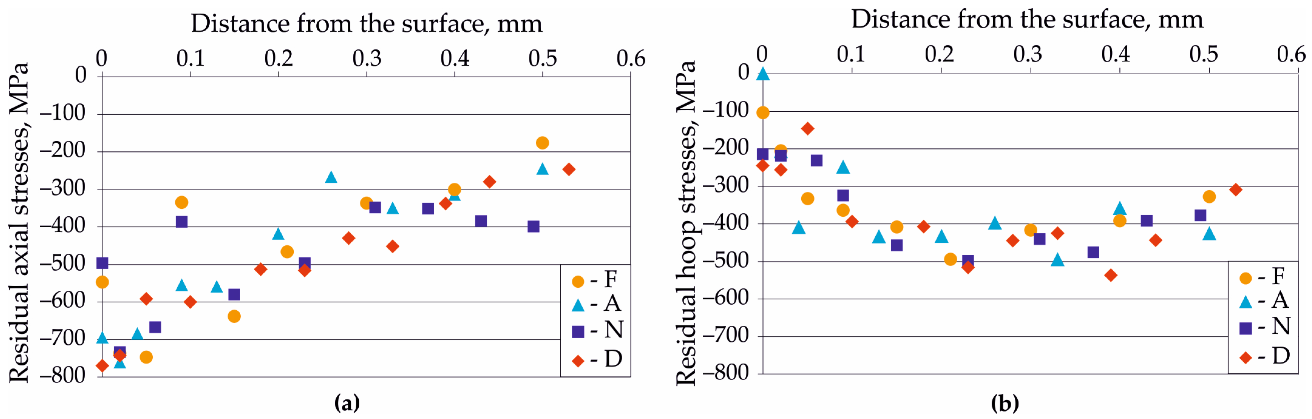
3.2.4. Residual Stress Distribution
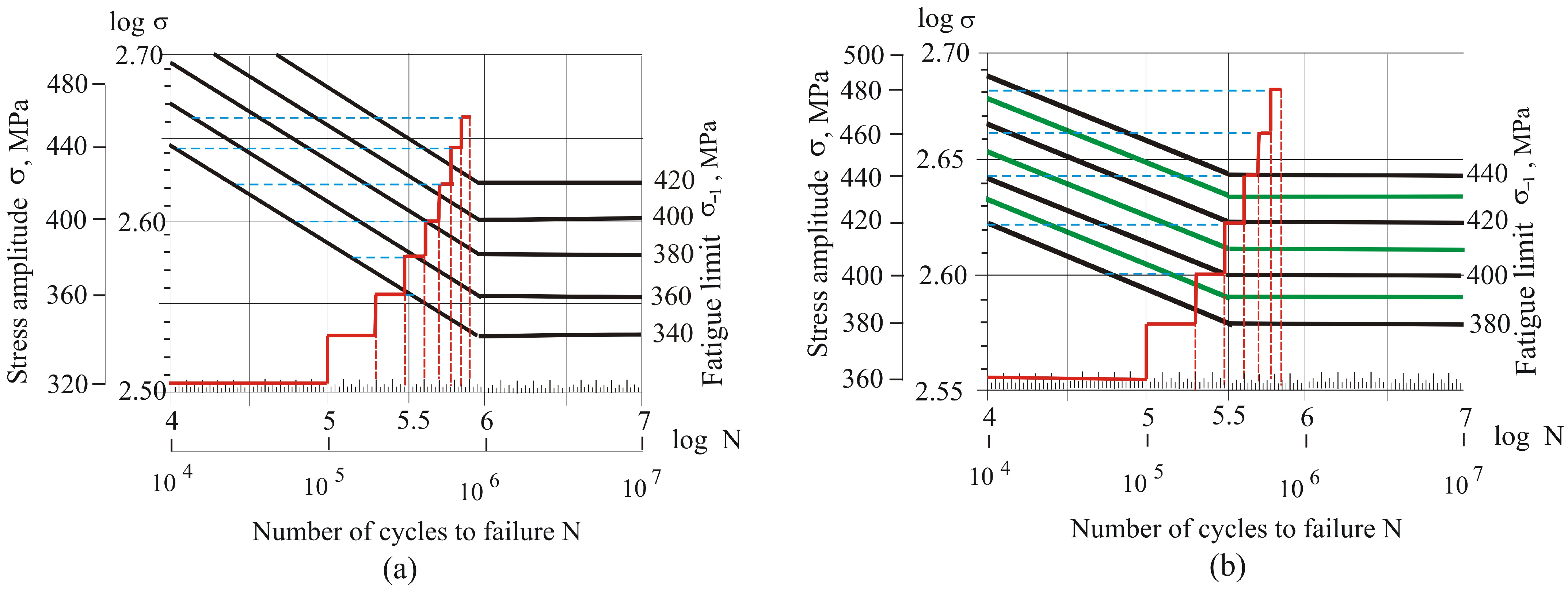
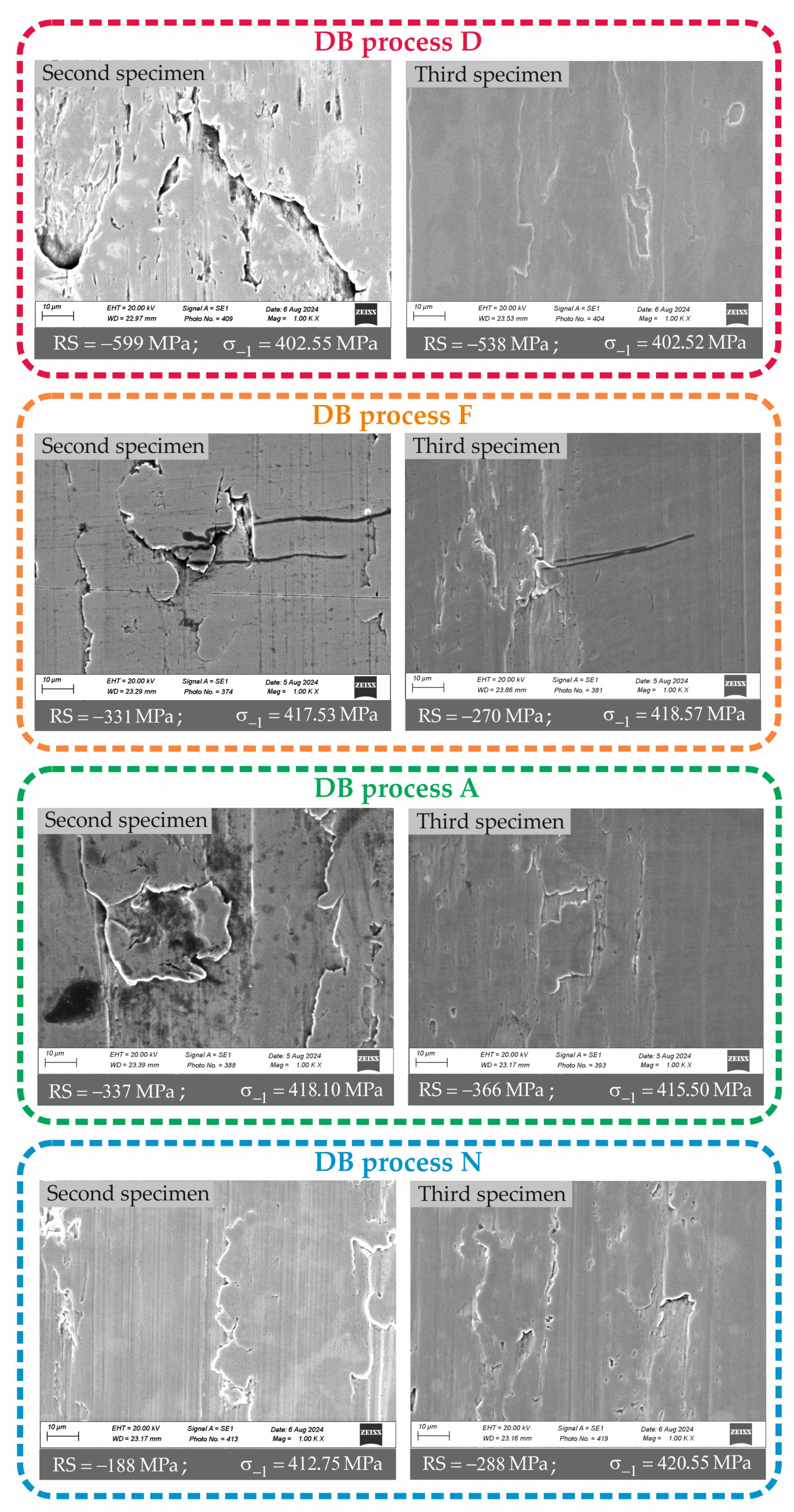
Figure 9 shows the residual stress distributions obtained by various DB processes, and Table 6 lists the residual stress measurement errors. The four DB processes lead to different surface residual stresses, with the largest absolute residual axial and hoop stress values achieved via the dry DB process (specimen D). Notably, no clear trend is observed for the influence of temperature on the surface axial and hoop residual stresses. In the surface and near-subsurface layers (up to 0.1 mm) there is significant scattering in the residual stress distribution introduced by the four processes, whereas at greater depths (exceeding 0.1 mm) this scattering is less. Irrespective of the burnishing conditions, the compressive zone depth exceeds 0.5 mm.

3.3. Fatigue Limits

Based on the principles of Locati′s method, to obtain a more accurate solution, the selected S-N curves must be as close as possible to the real ones. In the present study, the S-N curves (for turning and polishing and for DB) were selected based on our previous studies. The mechanical properties of the studied 316 CNASS are similar to those of the 304 CNASS investigated in [6]. The difference in the tensile strength and yield limit values for these two steel types is approximately 304 MPa. Their elongations are 45% and 41%, respectively. The S-N curves in [6] for 304 steel have fatigue limits of 440 MPa due to turning and polishing and 540 MPa due to the smoothing DB process. Since the 316 steel in the present study has lower strength (the yield limit and tensile strength are 60 MPa lower than the corresponding values of 304 steel [6]), the main S-N curves for 316 steel in a double-logarithmic coordinate system have fatigue limits of 380 MPa for turning and polishing and 420 MPa for the smoothing DB processes (Figure 10). The difference Δ σ in the stress amplitudes between any two adjacent levels is 20 MPa, and the number of cycles n for each step is 10 5 (see Figure 10).
The fatigue limit experimental results are listed in Table 7. All four DB processes significantly increase the fatigue limit of the specimens compared to turning and polishing. The largest increase from 365 MPa to 419 MPa (i.e., 14.79%) is observed in the samples from group F (flood lubrication), while the smallest increase from 365 MPa to 405 MPa (i.e., 10.96%) is recorded in the samples from group D (dry DB without cooling). Dry DB with air cooling or nitrogen cooling (groups A and N) results in an increase of 14.25% and 14.52%, respectively, which is essentially the same as that achieved by DB under flood lubrication. The fatigue limits of the samples that underwent DB under dry conditions increase with decreasing temperature. The smaller fatigue limit increase observed from dry DB without cooling (group D) can be explained by the resulting microstructure of the surface and subsurface layers. As noted in Section 3.2.1, dry DB processes form a submicrocrystalline structure with high atomic density in these layers, with correspondingly higher second-order microstresses. These microstresses lead to greater internal energy in these layers. These structural changes are most pronounced for group D specimens, in which the internal energy is highest. The introduced residual compressive macrostresses delay fatigue macrocrack formation. The increased internal energy is released as the macrocrack develops and the resistance to fatigue macrocrack growth in the affected layers is accordingly lowest for the dry DB process without cooling (group D). However, dry DB without cooling also leads to a surface texture with the largest negative skewness and a kurtosis significantly greater than three (see Table 5). This combination of shape roughness parameters has been demonstrated to significantly favor the tribological behavior of the surface in boundary friction and mixed lubrication friction conditions [46,59,60,61]. However, this combination of shape roughness parameters is unfavorable from a fatigue behavior perspective [62] as the deep valleys within the surface texture act as natural microstress concentrators. Previous research has experimentally proven that reducing the skewness value corresponds to a decrease in the fatigue limit of diamond-burnished CNASS specimens [50]; thus, the more negative the skewness, the lower the specimen’s fatigue limit.
It should be noted that the SI characteristics in Section 3.2 were obtained for cylindrical specimens with a diameter of 28 mm. The diamond-burnished surfaces of the fatigue specimens differ significantly both in in terms of their shape (hourglass-shaped) and in size (minimum diameter of 7.5 mm). As a result, the SI characteristics of the fatigue specimens will differ. To determine the effects of the introduced residual stresses and surface defects on the fatigue limits around the minimum diameters of the fatigued specimens, for the second and third specimens of each group, the residual axial stresses were measured and the surface defects were examined by SEM at a constant magnification. The obtained results are shown in Figure 11. This figure shows the most pronounced surface defects (whose origin is from turning) for each specimen.
The surface axial residual stresses were also measured in the same areas. The measured surface axial residual stresses in the fatigued specimens are smaller in absolute value compared to those introduced in the cylindrical specimens by the corresponding DB processes (see Figure 9). For both fatigued and cylindrical specimens dry DB without cooling (process D) introduces the largest surface axial residual compressive stresses, followed by processes A, F, and N. Despite the pronounced surface defects observed in some of the specimens, the fatigue limits for each pair of specimens processed by the same DB process are very similar. On this basis, it can be assumed that the fatigue macrocracks have been formed under the surface layer due to the introduced residual compressive macrostresses and the modified surface layers.

3.4. Choice of Sustainable DB Process

In terms of its environmental friendliness and impact on human health, DB under flood lubrication is not a sustainable process. However, this DB configuration is a conventional process, and the results achieved using this approach can serve as a reference in terms of the specimens’ SI and fatigue limit. All three dry DB processes satisfy the criteria for sustainable finishing processes as they are eco-friendly, do not have harmful impacts on human health, and do not involve costs for the purchase, recycling, and purification of LCL. From an economic perspective, the cheapest configuration is dry DB without cooling. The two sustainable processes A and N provide essentially the same fatigue limit as the conventional flooding DB process. Therefore, in applications where high fatigue strength is required, DB with cold air cooling should be chosen, as it provides a more favorable cost/quality ratio while also being more sustainable than the conventional LCL process. Overall, based on the obtained SI results and the known correlations between SI and tribological behavior under boundary and mixed lubrication conditions [46,57,59,61], dry DB without cooling is the most appropriate sustainable finishing process when increased wear resistance is required.

4. Conclusions

In this study, DB of 316 CNASS was performed as a smoothing process with the same magnitudes of the main governing factors but under four different lubrication and cooling conditions: (1) flood lubrication (process F); (2) dry conditions without cooling (process D); (3) dry, air cooled conditions with a temperature of −19 °C (process A); and (4) dry nitrogen cooled conditions with a temperature of −31 °C (process N).
As a result of this work, the following key findings were obtained:
  • All four DB processes provide mirror-finished surfaces, with roughness parameter Ra values from 0.041 to 0.049 μm. The ranking of the processes in terms of decreasing roughness is F, A, D, and N.
  • Processes F and D produce the highest microhardness, both on the specimens’ surface and at depth.
  • All the investigated DB processes introduce zones of significant residual compressive stresses deeper than 0.5 mm. Process D introduces the maximum compressive residual stresses (both axial and hoop) in the surface layer.
  • The dry DB processes (D, A, and N) form a submicrocrystalline structure with high atomic density, which is most pronounced for process D.
  • The three dry DB processes (D, A, and N) satisfy the criteria for sustainable finishing processes. When high fatigue strength is required, DB with cold air cooling should be chosen, as this configuration provides a more favorable cost/quality ratio. However, dry DB without cooling is the most suitable sustainable finishing process for applications where increased wear resistance is required.

Author Contributions

Conceptualization, J.M. and G.D.; methodology, J.M. and G.D.; software, J.M., G.D., V.D. and Y.A.; validation, J.M. and G.D.; formal analysis, J.M., G.D. and Y.A.; investigation, A.A., V.D., Y.A., K.A., G.D. and J.M.; resources, J.M. and G.D.; data curation, J.M. and G.D.; writing—original draft preparation, J.M. and G.D.; writing—review and editing, J.M. and G.D.; visualization, J.M., G.D., A.A., V.D. and Y.A.; supervision, J.M.; project administration, J.M. and G.D.; funding acquisition, J.M. and G.D. All authors have read and agreed to the published version of the manuscript.

Funding

This research was funded by the European Regional Development Fund within the OP. “Science and Education for Smart Growth 2014–2020”, Project CoC “Smart Mechatronics, Eco- and Energy Saving Systems and Technologies”, No.BG05M2OP001-1.002-0023.

Institutional Review Board Statement

Not applicable.

Informed Consent Statement

Not applicable.

Data Availability Statement

Data are contained within the article.

Conflicts of Interest

The authors declare no conflicts of interest.

Abbreviations

CNASSChromium–nickel austenitic stainless steel
CNCcomputer numerical control
DBdiamond burnishing
LCLlubricating cooling liquid
MQLminimum quantity lubrication
RCreference condition
SCWsurface cold working
SEMscanning electron microscopy
SIsurface integrity

References

  1. Maximov, J.T.; Duncheva, G.V.; Anchev, A.P.; Dunchev, V.P.; Argirov, Y.B.; Nikolova, M.P. Effects of heat treatment and diamond burnishing on fatigue behaviour and corrosion resistance of AISI 304 austenitic stainless steel. Appl. Sci. 2023, 13, 2570. [Google Scholar] [CrossRef]
  2. Baldissera, P. Deep cryogenic treatment of AISI 302 stainless steel: Part I—Hardness and tensile properties. Mater. Design 2010, 31, 4725–4730. [Google Scholar] [CrossRef]
  3. Baldissera, P.; Delprete, C. Deep cryogenic treatment of AISI 302 stainless steel: Part II—Fatigue and corrosion. Mater. Design 2010, 31, 4731–4737. [Google Scholar] [CrossRef]
  4. Hedayati, A.; Najafizadeh, A.; Kermanpur, A.; Forouzan, F. The effect of cold rolling regime on microstructure and mechanical properties of AISI 304L stainless steel. J. Mater. Process. Technol. 2010, 210, 1017–1022. [Google Scholar] [CrossRef]
  5. Kurc-Lisiecka, A.; Kalinowska-Ozgowicz, E. Structure and mechanical properties of austenitic steel after cold rolling. J. Achiev. Mater. Manuf. Eng. 2011, 44, 148–153. [Google Scholar]
  6. Maximov, J.T.; Duncheva, G.V.; Anchev, A.P.; Dunchev, V.P.; Argirov, Y.B. Effect of Diamond Burnishing on Fatigue Behaviour of AISI 304 Chromium-Nickel Austenitic Stainless Steel. Materials 2022, 15, 4768. [Google Scholar] [CrossRef]
  7. Dureau, C.; Novelli, M.; Arzaghi, M.; Massion, R.; Bocher, P.; Nadot, Y.; Grosdidier, T. On the influence of ultrasonic surface mechanical attrition treatment (SMAT) on the fatigue behaviour of the 304L austenitic stainless steel. Metals 2020, 10, 100. [Google Scholar] [CrossRef]
  8. Azar, V.; Hashemi, B.; Yazdi, M.R. The effect of shot peening on fatigue and corrosion behaviour of 316L stainless steel in Ringer’s solution. Surf. Coat. Technol. 2010, 204, 3546–3551. [Google Scholar] [CrossRef]
  9. Korzynski, M. Slide diamond burnishing. In Nonconventional Finishing Technologies; Korzynski, M., Ed.; Polish Scientific Publishers PWN: Warsaw, Poland, 2013. [Google Scholar]
  10. Khanna, N.; Agrawal, C.; Pimenov, D.Y.; Singla, A.K.; Machado, A.R.; da Silva, L.R.R.; Gupta, M.K.; Sarikaya, M.; Krolczyk, G.M. Review on design and development of cryogenic machining setups for heat resistant alloys and composites. J. Manuf. Process. 2021, 68, 398–422. [Google Scholar] [CrossRef]
  11. Adler, D.P.; Hii, W.W.-S.; Michalek, D.J.; Sutherland, J.W. Examining the role of cutting fluids in machining and efforts to address associated environmental/health concerns. Mach. Sci. Technol. 2006, 10, 23–58. [Google Scholar] [CrossRef]
  12. Klocke, F.; Eisenblätter, G. Dry cutting. CIRP Ann. 1997, 46, 519–526. [Google Scholar] [CrossRef]
  13. Narutaki, N.; Yamane, Y.; Tashima, S.; Kuroki, H. A new advanced ceramic for dry machining. CIRP Ann. Manuf. Technol. 1997, 46, 43–48. [Google Scholar] [CrossRef]
  14. Shokrani, A.; Dhokia, V.; Newman, S.T. Environmentally conscious machining of difficult-to-machine materials with regard to cutting fluids. Int. J. Mach. Tool. Manuf. 2012, 57, 83–101. [Google Scholar] [CrossRef]
  15. Debnath, S.; Reddy, M.M.; Yi, Q.S. Environmental friendly cutting fluids and cooling techniques in machining: A review. J. Clean. Prod. 2014, 83, 33–47. [Google Scholar] [CrossRef]
  16. Shokrani, A.; Dhokia, V.; Newman, S.T.; Imani-Asrai, R. An initial study of the effect of using liquid nitrogen coolant on the surface roughness of inconel 718 nickel-based alloy in CNC milling. Procedia CIRP 2012, 3, 121–125. [Google Scholar] [CrossRef]
  17. Bennett, E.O. Water based cutting fluids and human health. Tribol. Int. 1983, 16, 133–136. [Google Scholar] [CrossRef]
  18. Elsner, P.; Wilhelm, D.; Maibach, H.I. Irritant Contact Dermatitis irritant contact dermatitis and aging. Contact Dermat. 1990, 23, 265–269. [Google Scholar] [CrossRef]
  19. Shashidhara, Y.M.; Jayaram, S.R. Vegetable oils as a potential cutting fluid—An evolution. Tribol. Int. 2010, 43, 1073–1081. [Google Scholar] [CrossRef]
  20. Clapp, R.W.; Jacobs, M.M.; Loechler, E.L. Environmental and occupational causes of cancer: New evidence 2005–2007. Rev. Environ. Health 2008, 23, 1–37. [Google Scholar] [CrossRef]
  21. Mackerer, C.R. Health effects of oil mists: A brief review. Toxicol. Ind. Health 1989, 5, 429–440. [Google Scholar] [CrossRef]
  22. Said, Z.; Gupta, M.; Hegab, H.; Arora, N.; Khan, A.M.; Jamil, M.; Bellos, E. A comprehensive review on minimum quantity lubrication (MQL) in machining processes using nano-cutting fluids. Int. J. Adv. Manuf. Technol. 2019, 105, 2057–2086. [Google Scholar] [CrossRef]
  23. Jawahir, I.S.; Attia, H.; Biermann, D.; Duflou, J.; Klocke, F.; Meyer, D.; Newman, S.T.; Pusavec, F.; Putz, M.; Rech, J.; et al. Cryogenic manufacturing processes. CIRP Annals. Manuf. Technol. 2016, 65, 713–736. [Google Scholar] [CrossRef]
  24. Rosen, M.A.; Kishawy, H.A. Sustainable Manufacturing and Design: Concepts, Practices and Needs. Sustainability 2012, 4, 154–174. [Google Scholar] [CrossRef]
  25. Kuznetsov, V.P.; Smolin, I.Y.; Dmitriev, A.I.; Tarasov, V.G. Toward control of subsurface strain accumulation in nanostructuring burnishing on thermostrengthened steel. Surf. Coat. Technol. 2016, 285, 171–178. [Google Scholar] [CrossRef]
  26. Liska, K.; Kodacsy, J.; Liska, J. Investigation of microgeometry on diamond burnished surfaces. In Proceedings of the 8th research/expert conference with international participations “quality 2013”, Neum, Bosnia and Herzegovina, 6–8 June 2013; pp. 615–620. [Google Scholar]
  27. Sachin, B.; Narendranath, S.; Chakradhar, D. Effect of cryogenic diamond burnishing on residual stress and microhardness of 17–4 PH stainless steel. Mater. Today Proc. 2018, 5, 18393–18399. [Google Scholar] [CrossRef]
  28. Sachin, B.; Narendranath, S.; Chakradhar, D. Sustainable diamond burnishing of 17-4 PH stainless steel for enhanced surface integrity and product performance by using a novel modified tool. Mater. Res. Express 2019, 6, 046501. [Google Scholar]
  29. Sachin, B.; Narendranath, S.; Chakradhar, D. Effect of working parameters on the surface integrity in cryogenic diamond burnishing of 17-4 PH stainless steel with a novel diamond burnishing tool. J. Manuf. Process 2019, 38, 564–571. [Google Scholar]
  30. Nguyen, T.-T.; Van, A.-L. Machining and optimization of the external diamond burnishing operation. Mater. Manuf. Process. 2023, 38, 1276–1290. [Google Scholar] [CrossRef]
  31. Sachin, B.; Rao, C.M.; Naik, G.M.; Prasad, C.D.; Hebbale, A.M.; Vijeesh, V.; Rao, M. Minimum quantity lubrication and cryogenic for burnishing of difficult to cut material as a sustainable alternative. In Sustainable Machining Strategies for Better Performance, Lecture Notes in Mechanical Engineering; Springer: Singapore, 2021; pp. 61–69. [Google Scholar]
  32. Uehara, K.; Kumagai, S. Chip formation, surface roughness and cutting force in cryogenic machining. Ann. CIRP 1968, 17, 409–416. [Google Scholar]
  33. Maximov, J.T.; Duncheva, G.V. Effects of cryogenic- and cool-asisted burnishing on the surface integrity and operating behaviour of metal components: A review and perspectives. Machines 2024, 12, 312. [Google Scholar] [CrossRef]
  34. Diniz, A.; Micaroni, R. Cutting conditions for finish turning process—Aiming: The use of dry cutting. Int. J. Mach. Tool Manuf. 2002, 42, 899–904. [Google Scholar] [CrossRef]
  35. Yu, X.; Wang, L. Effect of various parameters on the surface roughness of an aluminium alloy burnished with a spherical surfaced polycrystalline diamond tool. Int. J. Mach. Tools Manuf. 1999, 39, 459–469. [Google Scholar] [CrossRef]
  36. Kuznetsov, V.; Makarov, A.; Skorobogatov, A.; Skorinina, P.; Luchko, S.; Sirosh, V.; Chekan, N. Influence of normal force on smoothing and hardening of the surface layer of steel 03X16N15M3T1 during dry diamond smoothing with a spherical indenter. Met. Process. 2022, 24, 6–22. (In Russian) [Google Scholar]
  37. Le, M.-T.; Van, A.-L.; Nguyen, T.T.; Dang, X.-B. Ecological design optimization of nozzle parameters for burnishing operation. J. Appl. Eng. Sci. 2023, 21, 686–697. [Google Scholar] [CrossRef]
  38. Le, M.-T.; Van, A.-L.; Nguyen, T.T. Impacts of burnishing variables on the quality indicators in a single diamond burnishing operation. J. Mech. Eng. 2023, 69, 155–168. [Google Scholar] [CrossRef]
  39. Varga, G.; Ferencsik, V. Experimental examination of surface micro-hardness improvement ratio in burnishing of external cylindrical workpieces. Cut. Tools Technol. Syst. 2020, 93, 114–121. [Google Scholar] [CrossRef]
  40. Felho, C.; Varga, G. 2D FEM investigation of residual stress in diamond burnishing. J. Manuf. Mater. Process 2022, 6, 123. [Google Scholar] [CrossRef]
  41. Konefal, K.; Korzynski, M.; Byczkowska, Z.; Korzynska, K. Improved corrosion resistance of stainless steel X6CrNiMoTi17-12-2 by slide diamond burnishing. J. Mater. Process. Technol. 2013, 213, 1997–2004. [Google Scholar] [CrossRef]
  42. Maximov, J.T.; Duncheva, G.V.; Anchev, A.P.; Ganev, N.; Amudjev, I.M.; Dunchev, V.P. Effect of slide burnishing method on the surface integrity of AISI 316Ti chromium-nickel steel. J Braz. Soc. Mech. Sci. Eng. 2018, 40, 194. [Google Scholar] [CrossRef]
  43. Okada, M.; Shinya, M.; Matsubara, H.; Kozuka, H.; Tachiya, H.; Asakawa, N.; Otsu, M. Development and characterization of diamond tip burnishing with a rotary tool. J. Mater. Process. Technol. 2017, 244, 106–115. [Google Scholar] [CrossRef]
  44. Tanaka, H.; Ishii, W.; Yanagi, K. Optimal Burnishing Conditions and Mechanical Properties of Surface Layer by Surface Modification Effect Induced of Applying Burnishing Process to Stainless Steel and Aluminum Alloy. J. Jpn. Soc. Technol. Plast. 2011, 52, 726–730. (In Japanese) [Google Scholar]
  45. Korzynski, M.; Dudek, K.; Korzynska, K. Effect of slide diamond burnishing on the surface layer of valve stems and the durability of the stem-graphite seal friction pair. Appl. Sci. 2023, 13, 6392. [Google Scholar] [CrossRef]
  46. Korzynski, M.; Dudek, K.; Kruczek, B.; Kocurek, P. Equilibrium surface texture of valve stems and burnishing method to obtain it. Tribol. Int. 2018, 124, 195–199. [Google Scholar] [CrossRef]
  47. Korzynski, M.; Dudek, K.; Palczak, A.; Kruczek, B.; Kocurek, P. Experimental models and correlations between surface parameters after slide diamond burnishing. Meas. Sci. Rev. 2018, 18, 123–129. [Google Scholar] [CrossRef]
  48. Skoczylas, A.; Zaleski, K.; Matuszal, J.; Ciecielag, K.; Zaleski, R.; Gorgol, M. Influence of slide burnishing parameters on the surface layer properties of stainless steel and mean positron lifetime. Materials 2022, 15, 8131. [Google Scholar] [CrossRef] [PubMed]
  49. Duncheva, G.V.; Maximov, J.T.; Anchev, A.P.; Dunchev, V.P.; Argirov, Y.B.; Velkov, S. Modeling and optimization of surface integrity and sliding wear resistance of diamond-burnished holes in austenitic stainless steel cylinder lines. Machines 2023, 11, 872. [Google Scholar] [CrossRef]
  50. Maximov, J.T.; Duncheva, G.V.; Anchev, A.P.; Dunchev, V.P. Explicit correlation between surface integrity and fatigue limit of surface cold worked chromium-nickel austenitic stainless steels. Int. J. Adv. Manuf. Technol. 2024, 133, 6041–6058. [Google Scholar] [CrossRef]
  51. ISO 6892-1:2019; Metallic materials—Tensile Testing—Part1: Method of Test at Room Temperature. ISO: Geneva, Switzerland, 2019.
  52. DIFFRAC.DQUANT. Quantitative Analysis from Calibration to Reporting; Bruker AXS GmbH: Karlsrue, Germany, 2018. [Google Scholar]
  53. Bulgarian National Standard 5297:1983; Metals—Fatigue Test Methods. BDS: Sofia, Bulgaria, 1983. (In Bulgarian)
  54. Miner, M.A. Cumulative damage in fatigue. J. Appl. Mech. 1945, 3, 159–164. [Google Scholar] [CrossRef]
  55. Maximov, J.T.; Duncheva, G.V.; Anchev, A.P.; Dunchev, V.P.; Ichkova, M.D. Improvement in fatigue strength of 41Cr4 steel through slide diamond burnishing. J. Braz. Soc. Mech. Sci. Eng. 2020, 42, 197. [Google Scholar] [CrossRef]
  56. Nikitin, I.; Altenberger, I.; Scholtes, B. Effects of deep rolling at elevated and low temperatures on the isothermal fatigue of AlSl304. Altern. Process. 2005, 70, 185–190. [Google Scholar]
  57. Pawlus, P.; Reizer, R.; Wieczorowski, M. Functional Importance of Surface Texture Parameters. Materials 2021, 14, 5326. [Google Scholar] [CrossRef] [PubMed]
  58. Zhang, J.; Pei, Z.J. Characterization Methods for Surface Integrity. In Surface Integrity in Mashining; Paulo, J., Ed.; Springer: London, UK, 2010; ISBN 978-1-84-882-974-2. [Google Scholar]
  59. Sedlacek, M.; Podgornik, B.; Vizintin, J. Correlation between standard roughness parameters skewness and kurtosis and tribological behaviour of contact surface. Tribol. Int. 2012, 48, 102–112. [Google Scholar] [CrossRef]
  60. Duncheva, G.V.; Maximov, J.T.; Anchev, A.P.; Dunchev, V.P.; Argirov, Y.B. Improvement in wear resistance performance of CuAl8Fe3 single-phase aluminum bronze via slide diamond burnishing. J. Mater. Eng. Perform. 2022, 31, 2466–2478. [Google Scholar] [CrossRef]
  61. Duncheva, G.V.; Maximov, J.T.; Anchev, A.P.; Dunchev, V.D.; Argirov, Y.B.; Kandeva-Ivanova, M. Enhancement of the wear resistance of CuAl9Fe4 sliding bearing bushings via diamond burnishing. Wear 2022, 510–511, 204491. [Google Scholar] [CrossRef]
  62. Zabala, A.; Blunt, L.; Tato, W.; Aginagalde, A.; Gomez, X.; Llavori, I. The use of areal surface topography characterisation in relation to fatigue performance. MATEC Web Conf. 2018, 165, 14013. [Google Scholar] [CrossRef]
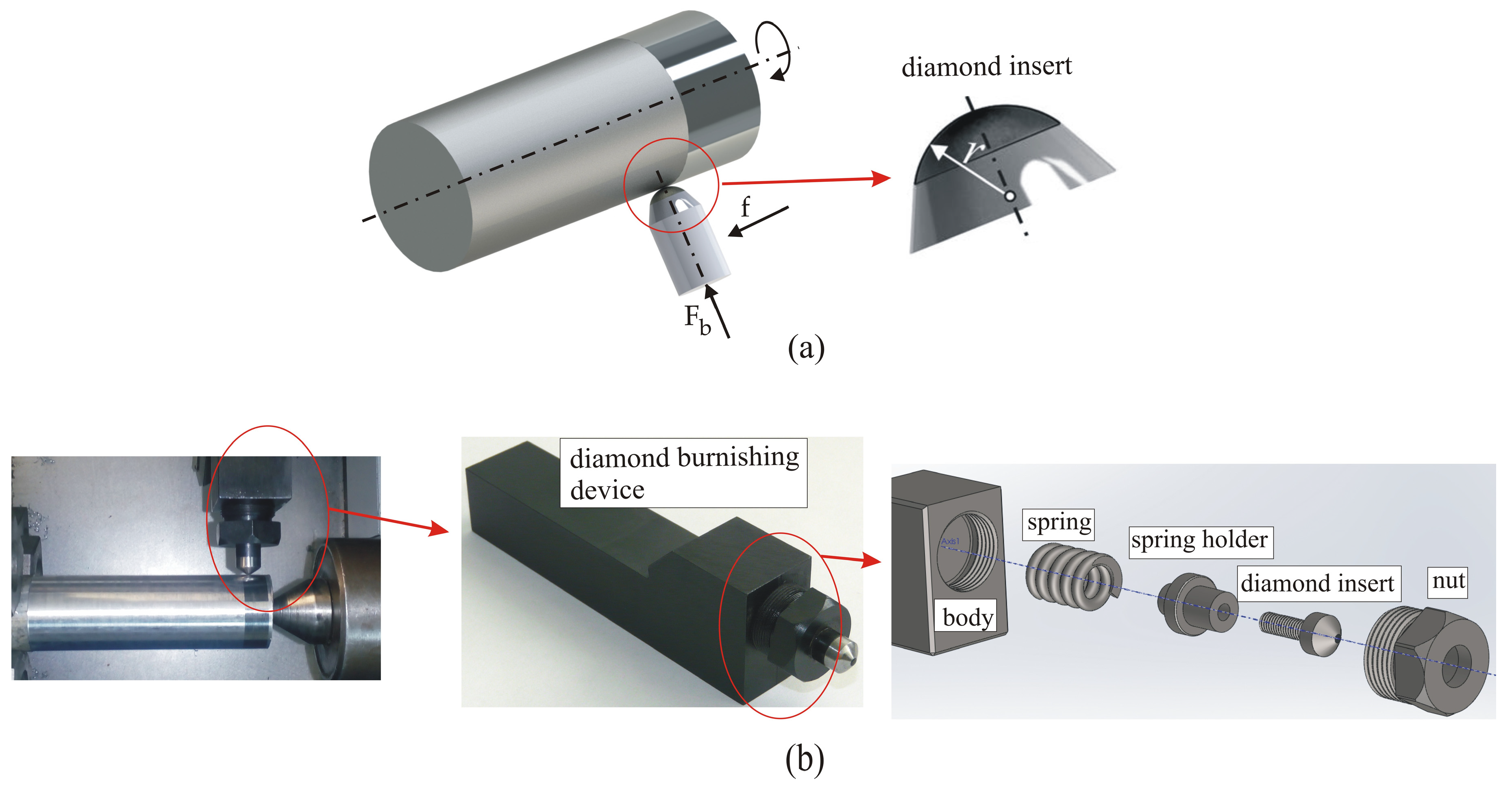
Figure 1. Specimen geometry: (a) tensile test; (b) rotating bending fatigue test.
Applsci 14 09031 g001
Figure 2. Kinematics of DB: (a) scheme and governing factor designation; (b) burnishing device.
Applsci 14 09031 g002
Figure 3. Graphical interpretation of Locati’s method: (a) step load; (b) damage–stress curve.
Applsci 14 09031 g003
Figure 4. Microstructures of the surface and subsurface layers obtained by DB under different conditions: (a) D (dry burnishing); (b) F (flood lubrication); (c) A (air cooling); (d) N (nitrogen cooling).
Applsci 14 09031 g004
Figure 5. Roughness profiles of the diamond-burnished specimens: (a) F; (b) A; (c) N; (d) D.
Applsci 14 09031 g005
Figure 6. Effects of different processes on roughness parameter Ra.
Applsci 14 09031 g006
Figure 7. Microhardness obtained via turning and different DB processes: (a) surface microhardness; (b) microhardness distribution along the depth from the surface.
Applsci 14 09031 g007
Figure 8. Phase analysis outcomes.
Applsci 14 09031 g008
Figure 9. Residual stress distribution: (a) axial; (b) hoop.
Applsci 14 09031 g009
Figure 10. Assumed S-N curves: (a) turning and polishing; (b) DB.
Applsci 14 09031 g010
Figure 11. SEM images of the surface texture of fatigue specimens.
Applsci 14 09031 g011
Table 1. Magnitudes of the governing factors used in this study.
DB Process Typer, mmFb, Nf, mm/revv, m/min
Smoothing33000.0760
Table 2. Characteristics of the residual stress X-ray measurement.
Measuring DeviceBruker D8 Advance Diffractometer
X-ray tubeLong focus Cr—Kα
Crystallographic planeFe(γ)—(220)
Diffraction angle (2θ)128.78° (124° 133°)
Measuring methodOffset coupled TwoTheta/Theta (sin 2ψ method)
Scan modeContinuous PSD fast
X-ray detectorSSD160-2 (1D scanning)
Collimator spot sizeStandard Φ1.0 mm
Measurement time for single scanApprox. 35 s
Elastic constant s1 1.352 × 10 6
Elastic constant 1/2s2 6.182 × 10 6
Voltage30 kV
Current40 mA
Step size0.5°
Time for step1 s
Table 3. Chemical compositions (in wt %) of the used AISI 316 steels.
BarFeCSiMnPSCrNiNbTiMoCuCoWV
ϕ3066.80.0450.131.770.0270.01718.79.440.0360.0051.990.5750.1840.1180.074
Table 4. Main mechanical characteristics of the tested AISI 316 steels.
Hot-Rolled BarYield Limit, MPaTensile Strength, MPaElongation, %Hardness, HB
ϕ 30 mm 372 + 3 4 678 + 6 5 45.5 ± 0.5 207 ± 2
Table 5. Comparison of 2D roughness parameters obtained via DB under different conditions.
Specimen2D Roughness Parameters
R a
μ m
R q
μ m
R p
μ m
R v
μ m
R s k R k u R k
μ m
R p k
μ m
R v k
μ m
F0.0410.0540.150.255−0.3296.5270.1340.0580.066
A0.0470.0640.1970.293−0.5597.5420.1460.0640.117
N0.0490.0620.1720.241−0.2554.9460.1560.0690.081
D0.0480.0660.1640.406−1.2911.0320.1490.0650.115
Table 6. Errors in residual stress measurement.
Specimens
FAND
Depth
mm
Error, MPaDepth
mm
Error, MPaDepth
mm
Error, MPaDepth
mm
Error, MPa
AxialHoopAxialHoopAxialHoopAxialHoop
0110.830.40130.637.6084.953.20130.188.7
0.0277.628.50.0229.233.50.0260.870.20.0262.977.1
0.0560.735.50.052148.70.0648.350.70.0561.934.2
0.1256.853.10.0733.3750.0936.760.50.129.535.4
0.1735.2520.1333.447.40.1527.736.10.1837.637.7
0.2233.523.70.2121.844.60.2333.019.80.2336.438.7
0.33736.90.2634.322.50.3130.440.30.2841.537.8
0.3627.541.90.3224.434.20.3732.728.20.3329.331.5
0.433.624.80.4639.431.10.4326.6300.3946.031.4
0.4847.922.20.53533.50.4937.333.90.4427.334.7
---------0.4940.335.7
Table 7. Fatigue limits due to different finishing processes.
Finishing Process σ 1 ( 1 ) , M P a σ 1 ( 2 ) , M P a σ 1 ( 3 ) , M P a σ 1 , MPa σ 1 Scattering, MPa
Turning and polishing367.25367.25360.94365 + 2 / 5
DB—F422.20417.53418.57419 + 3 / 2
DB—A418.80418.10415.50417 + 1 / 2
DB—N420.70412.75420.55418 + 2 / 5
DB—D408.50402.55402.52405 + 3 / 3
Disclaimer/Publisher’s Note: The statements, opinions and data contained in all publications are solely those of the individual author(s) and contributor(s) and not of MDPI and/or the editor(s). MDPI and/or the editor(s) disclaim responsibility for any injury to people or property resulting from any ideas, methods, instructions or products referred to in the content.

