Article

AcpAS: An Advanced Circularly Polarized Antenna Structure for an Airborne Relay Communication System

1
The 63rd Research Institute, National University of Defense Technology, Nanjing 210001, China
2
Laboratory for Big Data and Decision, National University of Defense Technology, Nanjing 210001, China
*
Author to whom correspondence should be addressed.
Appl. Sci. 2024, 14(19), 9041; https://doi.org/10.3390/app14199041
Submission received: 8 September 2024 / Revised: 2 October 2024 / Accepted: 3 October 2024 / Published: 7 October 2024

Abstract

:
The airborne relay system is an important support for improving the stability of communication systems in complex electromagnetic environments. As a key component of the airborne relay system, the antenna needs to have characteristics such as high gain, dual circular polarization, wide beam coverage, and miniaturization. Based on the septum circular polarizer, this paper proposes a high-performance circularly polarized antenna structure suitable for airborne relay systems, named AcpAS. The structure consists of a coaxial feed port, a coaxial-to-waveguide transition, a septum circular polarizer, and a parabolic metal housing. Based on this structure, two antennas operating at 19.6 GHz to 21.6 GHz and 29.2 GHz to 31.2 GHz are designed in this paper. Simulated and measured results show that the two antennas have dual circular polarization characteristics, with beam coverage range of more than ±55° for gains higher than 0 dBi, and the radiation patterns exhibit good symmetry and wide-beam coverage characteristics.

1. Introduction

With the rapid development of informatization, communication equipment such as wireless communication, satellite navigation, and radar systems are widely used, making the electromagnetic environment increasingly complex. Especially in emergencies such as natural disasters, accidents, or terrorist attacks, once the communication infrastructure is damaged or overloaded, the stability of the communication system is greatly challenged. This may lead to communication interruptions or delays, severely affecting rescue and emergency response operations. Therefore, in complex electromagnetic environments or emergency situations, emergency communication systems play a crucial role in ensuring communication stability and providing network emergency support [1,2,3].
The airborne relay communication system is essential to the emergency communication system. The airborne platform, by carrying real-time information distribution or airborne forwarding payloads, can support the real-time distribution of information, relay signals, and expand the coverage of communication, featuring wide coverage, low latency, high mobility, and strong practicality, effectively enhancing the deployment capabilities of the communication system in emergencies such as major events, natural disasters, accident disasters, and social security incidents [4,5,6,7].
In the airborne relay communication system, to adapt to the characteristics of the low altitude of the airborne platform and the limited payload, and at the same time to improve anti-interference performance and reduce polarization mismatch, the design of the antenna needs to consider miniaturization, high gain, wide beam or half-space beam coverage, dual circular polarization (CP), etc. [8,9,10]. Moreover, it is better for the antenna to operate at the K-/Ka-bands, which can directly adapt to existing satellite communication terminals, ensuring emergency communication when satellite communication is limited.
In satellite communication systems, multi-beam antennas or phased arrays are commonly used to realize beam coverage or beam scanning functions for specified areas to achieve dual-CP and wide-area coverage [11,12,13,14]. However, in airborne relay communication systems, multi-beam antennas or phased arrays are difficult to apply: multi-beam or phased array antennas often contain multiple antenna elements, along with complex control or feeding networks, which would bring additional weight, power consumption, and technical complexity. Therefore, traditional multi-beam antennas and phased arrays are not suitable for airborne platforms with limited payload and power resources. Adopting a miniaturized wide-beam single-beam antenna structure, combined with time-division multiple access technology, is an effective solution for the antenna system of the airborne relay platform.
In view of this, this paper designs and proposes an antenna structure suitable for airborne relay communication systems. The antenna can operate at the K-band or the Ka-band, with dual-CP, a wide beam width, and features such as high gain and miniaturization.
The main contributions of this paper are as follows:
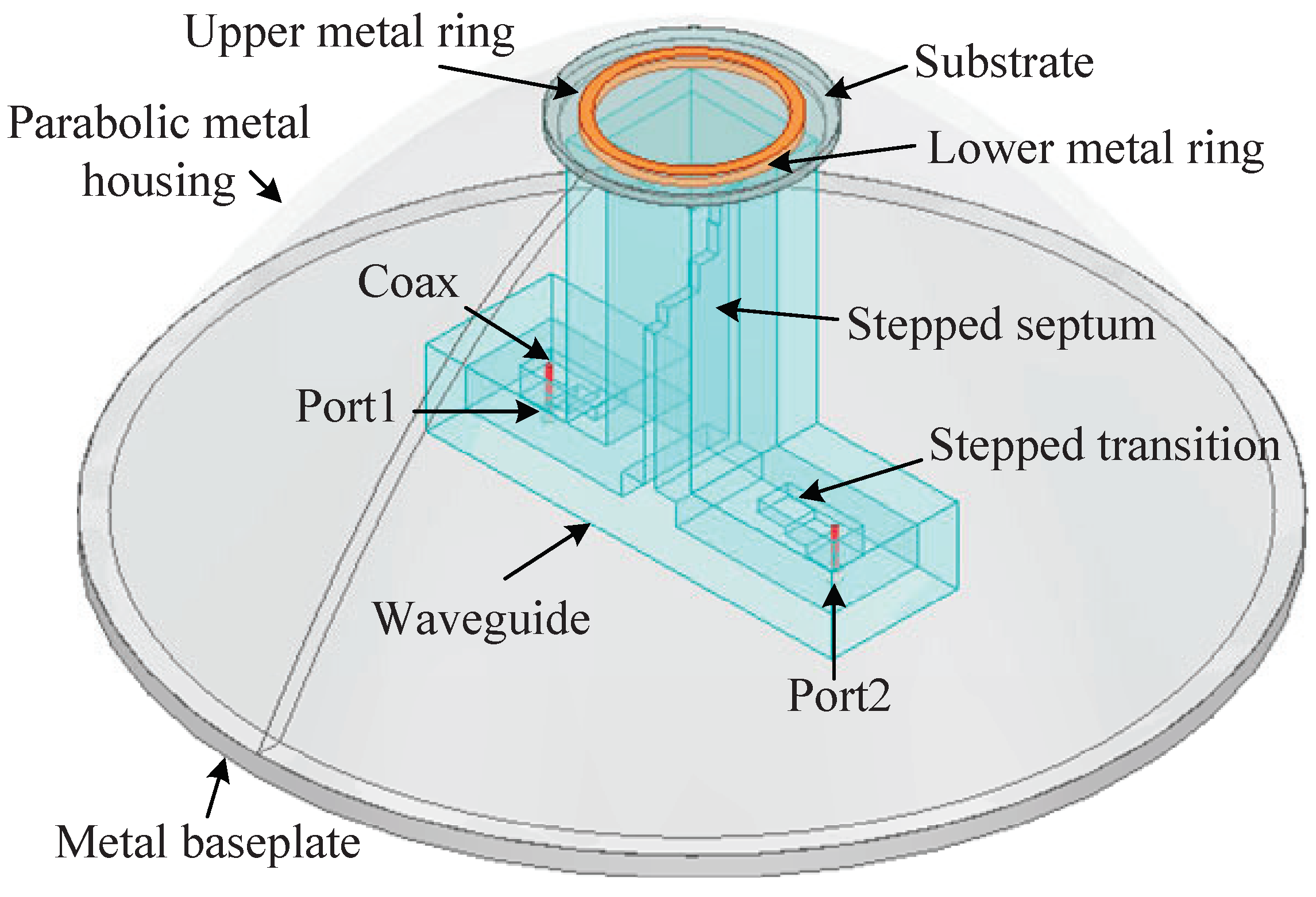
  • This paper proposes a wide-beam dual-CP antenna that operates at the K- and Ka-bands, respectively, using a stepped septum polarizer to achieve dual-CP radiation at the K- and Ka-bands, and the beam width is broadened by loading a parabolic metal housing.
  • This paper optimizes the septum polarizer for the antenna element and uses a side-fed coaxial-waveguide transition as the input structure of the septum polarizer, effectively reducing the impact of feeding structure errors on the performance of the septum polarizer.
  • Extensive simulations and measurements were conducted on the two designed wide-beam dual-CP antennas, and the results show that the antennas have the characteristics of dual-CP, wide-beam coverage, and miniaturization.
The structure of this paper is as follows. Section 2 introduces related works. Section 3 describes the design details of the antenna. Section 4 evaluates the performance of the antenna through experiments. Finally, Section 5 summarizes this whole paper.

2. Related Works

With the rapid development of communication technology and changes in the communication environment, CP and dual-CP technologies have made significant advancements. Currently, many structures and processes for dual-CP antennas have been proposed: a typical method is to use a feeding network, which can output two signals with equal amplitude and phase orthogonal to each other [15,16,17,18,19]. This type of dual-CP antenna exhibits excellent directional radiation performance. However, the feeding network and the 90-degree phase shifter have complex structures and high design requirements, which can cause additional losses, thereby reducing the radiation efficiency of the antenna. Scholars have proposed antenna designs based on square slot [20,21,22,23,24,25] structures and monopole antenna structures [26,27]. These two types of dual-CP antennas usually have advantages such as wide bandwidth, low profile, and ease of fabrication. However, this type of antenna has a bidirectional radiation characteristic, which severely limits its application in communication systems. Additionally, there are some multi-feed dual-CP dual-band antennas [28,29,30,31,32,33,34,35,36] that achieve dual-band and dual-CP through multi-feeding ports and array forms but cannot achieve wide-beam coverage, or that rely on feeding networks to realize angle scanning, making them unsuitable for airborne platforms. Moreover, horn antennas are also frequently used to generate dual-CP radiation [37,38,39,40,41]. However, due to the characteristics of horn antennas, the beam width of the antennas is generally narrow, unable to meet the requirements for wide-beam coverage.
Given that, this paper focuses on the destination of the antenna structure suitable for airborne relay communication systems, with the merits of dual-CP, wide beam width, and features such as high gain and miniaturization.

3. Design of AcpAS

The AcpAS antenna structure designed in this paper is shown in Figure 1. The figure shows the simulation model of the AcpAS. The antenna was simulated and optimized using ANSYS HFSS EM simulation software (2024 R2) via the finite element method (FEM). The antenna consists of a metal base, a coaxial feeding port, a stepped septum polarizer, a parabolic metal housing, a dielectric substrate, and two metal rings. One of the coaxial feeding ports is for feeding, and the other is matched. CP waves are formed through the waveguide and the septum polarizer. There is a circular opening on the top of the parabolic metal housing, inlaid with a dielectric substrate, and metal rings are printed on the top and bottom surfaces of the dielectric substrate. The circularly polarized waves are radiated through the metal cover and the metal rings, forming a wide-beam coverage CP wave.

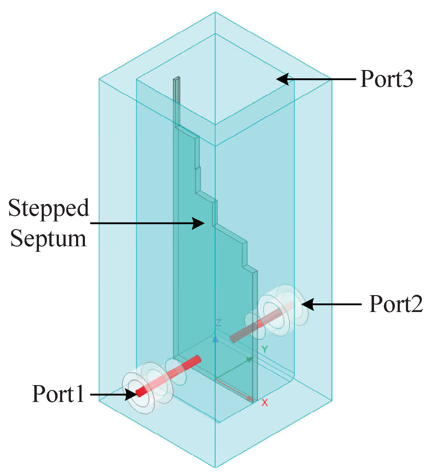
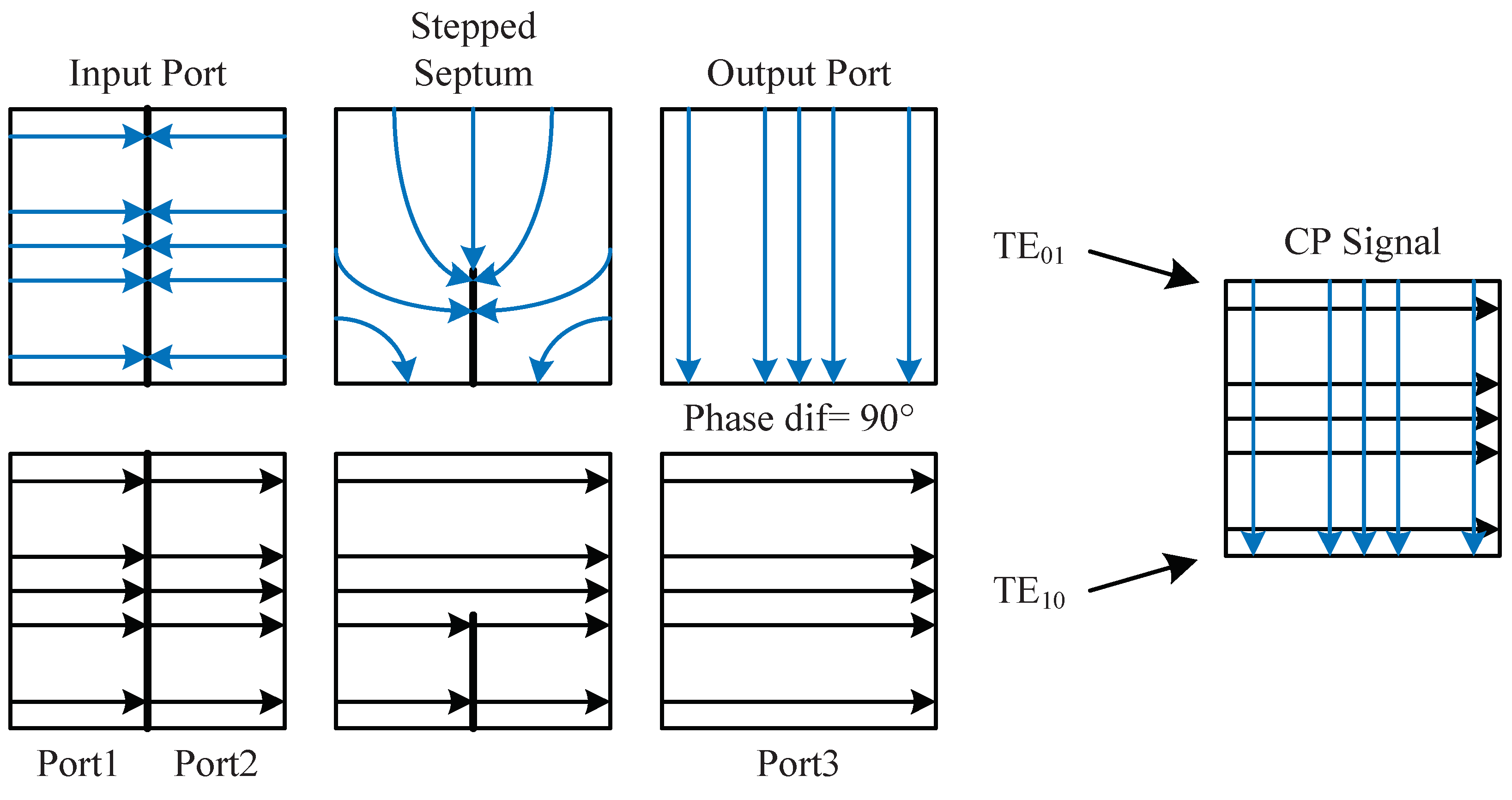
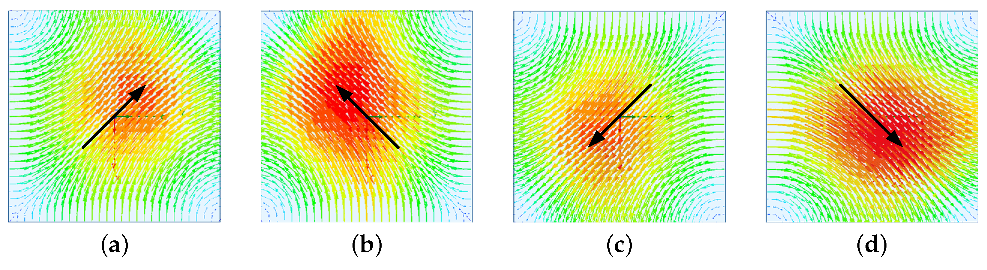
3.1. Design of the Septum Polarizer

The performance of the septum polarizer determines the CP performance of the antenna [42,43]. It achieves circular polarization by inserting a stepped metal septum into a square waveguide. Figure 2 shows the ANSYS HFSS simulation model of a common structure of the septum polarizer, where Port 1 and Port 2 are input ports, which are rectangular waveguides excited by a coax, and Port 3 is the square waveguide output port.
The TE10 mode input from the rectangular waveguide port is converted into two orthogonal TE10 and TE01 modes in the square waveguide after passing through the septum. For the TE10 mode, the septum has no effect on its propagation constant. For the TE01 mode, the septum is similar to a fin-line or ridge waveguide, which introduces phase delay. By adjusting the parameters of each step of the septum, the phase difference between the two orthogonal modes is made to be 90°, thereby forming a CP wave at the output port. The field pattern structure of the polarizer is shown in Figure 3. As can be seen from the field pattern structure of the septum polarizer, feeding Port 1 or Port 2 individually can form left-hand circularly polarized (LHCP) waves or right-hand circularly polarized (RHCP) waves at the output ports, respectively. Therefore, the adoption of septum polarizer can achieve dual-CP. In addition, feeding Port 1 and Port 2 with equal amplitude and in-phase or reverse-phase will form linearly polarized (LP) waves at the output ports.
The key technical specification in the design of the septum polarizer lies in its CP axial ratio (AR), which is mainly influenced by two factors: one is the amplitude difference between the two modes, and the other is the phase difference deviating from 90° between the two modes. From the perspective of the S-parameters, the septum polarizer can be regarded as a four-port network. Define the port parallel to the septum as Port 3 and the port perpendicular to the septum as Port 4. The AR caused by the amplitude difference is
A R 1 = 20 l g | S 13 S 14 | = 10 l g ( 1 | S 33 | 2 )
The AR produced by the phase difference deviating from 90° is
A R 2 = 20 l g | S 11 + S 14 S 13 S 14 |
where A R 1 is the AR generated by the amplitude difference, A R 2 is the AR produced by the phase difference deviating from 90°, S 13 is the transmission coefficient from Port 3 to Port 1, S 14 is the transmission coefficient from Port 4 to Port 1, and S 33 is the reflection coefficient at Port 3.
Then, it can be considered that the AR of the circular polarizer is A R = A R 1 + A R 2 (dB). Therefore, to reduce the AR of the septum polarizer, it is necessary to optimize the design of the steps to make the amplitudes of the two modes as equal as possible and the phase difference as close to 90° as possible.
Another key technical specification of the septum polarizer is the isolation between input ports, which is mainly caused by the standing wave of signals parallel to the septum. By optimizing the design of the steps, the standing wave of signals parallel to the septum can be reduced, thereby improving the isolation between the two senses of rotation of the septum polarizer.

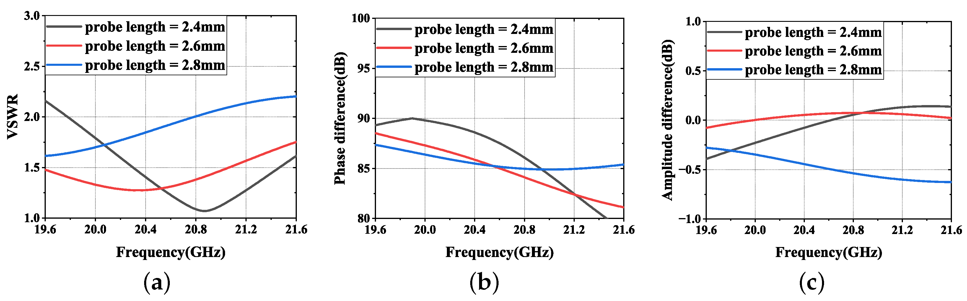
3.2. Optimization Design of the Coaxial to Waveguide Transition

As shown in Figure 2, the widely used septum polarizer currently adopts a direct insertion method for the coaxial port [41]. This form of structure is simple and easy to analyze. However, the performance of the septum polarizer is sensitive to the insertion length of the coaxial probe. As shown in Figure 4, when there is a ±0.2 mm change in the probe length, significant changes occur in the performance of the K-band septum polarizer, such as the voltage standing wave ratio (VSWR) and AR. In engineering implementations, errors due to machining or coaxial port installation may lead to changes in the length of the probe inserted into the waveguide, causing a sharp deterioration in the performance of the septum polarizer.
R. Levy and L. W. Hendrick proposed the in-line coaxial-waveguide transition structure [44]. Based on this, M. Durga et al. proposed an in-line transition structure based on third-order impedance transformation [45], as shown in Figure 5. The coaxial probe and the waveguide are in a straight line, with the probe inserted into the bottom short-circuit plate of the waveguide and connected to the stepped structure inside the waveguide. However, when applied to a septum polarizer, due to the size limitations of K/Ka-band waveguides, the feedback structure can cause overlap between the two coaxial ports, making it difficult to fabricate. In response to this, this paper proposes a side-fed coaxial-to-waveguide transition.
The schematic diagram of the side-fed coaxial-to-waveguide transition is shown in Figure 6. Similar to the direct insertion method, the coaxial probe is inserted into the waveguide from the side and connects to or is inserted into the stepped structure inside the waveguide. The probe inside the waveguide generates excitation and achieves the transformation from TEM mode to TE10 mode, and the stepped structure realizes impedance matching.
In AcpAS, a third-order stepped impedance matching structure is used. Typically, the length of the impedance matching step is a quarter of the wavelength, and the height conforms to the Chebyshev function [46]. Based on the Chebyshev impedance transformation, the initial step height and length are determined, a simulation model is established, and reasonable optimization is conducted. The parameters of the impedance matching steps operating in the K-band and Ka-band are shown in Table 1, and the meaning of each parameter in the table is shown in Figure 6.

3.3. Design of Antenna

As shown in Figure 1, the AcpAS antenna structure includes, in addition to the coaxial port, waveguide, and septum polarizer, other components such as a metal base plate, a parabolic metal housing, a dielectric substrate, and metal rings. The metal base plate is mainly used for installing the waveguide and the parabolic metal housing. The top of the metal housing has a circular opening, inside of which the dielectric substrate is installed. The dielectric substrate is made of Rogers 5880 material. Metal rings of the same size are etched on the upper and lower sides of the dielectric substrate.
When the antenna is in operation, Port 1 is fed, and Port 2 is matched. The septum circular polarizer forms a RHCP wave. On the contrary, when Port 2 is fed and Port 1 is matched, an LHCP wave is produced. The CP wave excites the metal rings to generate radiation. The parabolic metal housing serves to expand the beam width, achieving wide-beam coverage with dual-CP. Furthermore, based on the characteristics of the septum polarizer, by feeding equal amplitude and in-phase or equal amplitude and opposite-phase signals to the two ports, horizontal or vertical polarized waves can also be generated.

4. Evaluation

In this section, we first evaluate the AcpAS structure via extensive simulations. Additionally, we make a prototype on the AcpAS antennas and conduct prototype tests on the AcpAS structure. The image of the antenna prototypes is shown in Figure 7.

4.1. Simulation on the Components of AcpAS

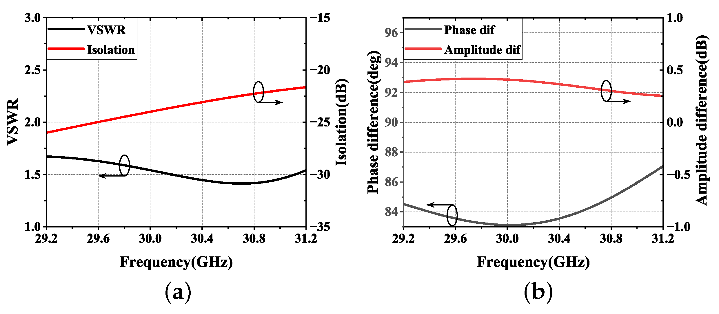
4.1.1. Simulation on the Septum Polarizer

The septum polarizer was simulated and optimized using ANSYS HFSS EM simulation software. Moreover, polarizers designed for operating frequencies of 19.6 GHz–21.6 GHz and 29.2 GHz–31.2 GHz were developed. Figure 8 shows the structure of the polarizer, and Table 2 provides the specific length parameters of K-band and Ka-band, where a is the width of the square waveguide, L is the length of the waveguide, d is the thickness of the septum, l 0 l 5 are the lengths of each step, and a 0 a 5 are the heights of each step.
Figure 9 and Figure 10, respectively, show the distribution of the electric field vector at the output port of the septum polarizer at 20.6 GHz over one time period T, when Port 1 is fed and Port 2 is matched, and when Port 2 is fed and Port 1 is matched. It can be observed that when only Port 1 is fed, the septum polarizer generates RHCP waves, and when only Port 2 is fed, the septum polarizer generates LHCP waves.
Figure 11 and Figure 12, respectively, show the simulation results of the VSWR, port isolation, phase difference between the two modes, and amplitude difference between the two modes for the designed K-band and Ka-band septum polarizers. It can be seen that for the K-band septum polarizer, within its operating frequency band, VSWR ≤ 1.6, port isolation ≤ 14 dB, the phase difference between the two modes is ≥86.3°, and the amplitude difference ≤ 0.1 dB; for the Ka-band septum polarizer, within its operating frequency band, VSWR ≤ 1.6, port isolation ≤ 14 dB, the phase difference between the two modes ≥ 83.1°, and the amplitude difference ≤ 0.4 dB. Both septum polarizers exhibit good performance and meet the feed requirements of dual-CP antennas.

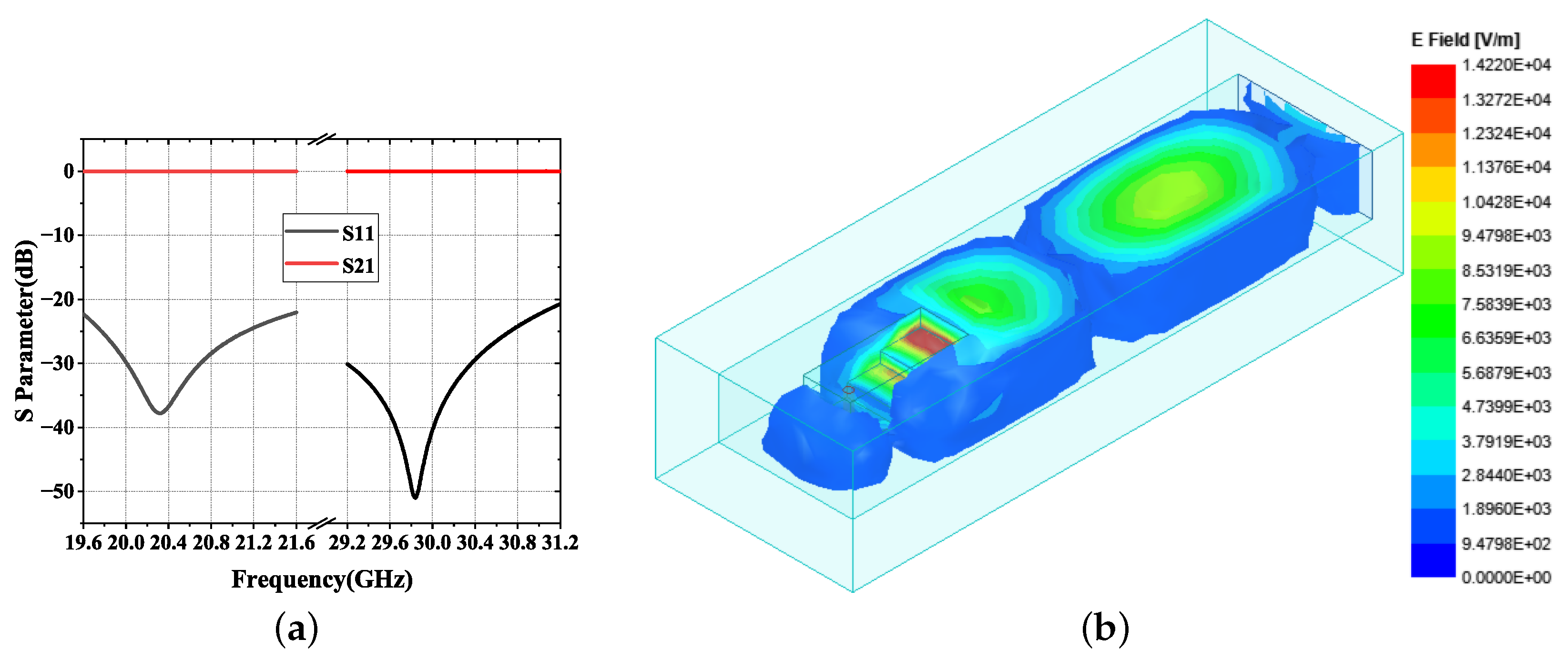
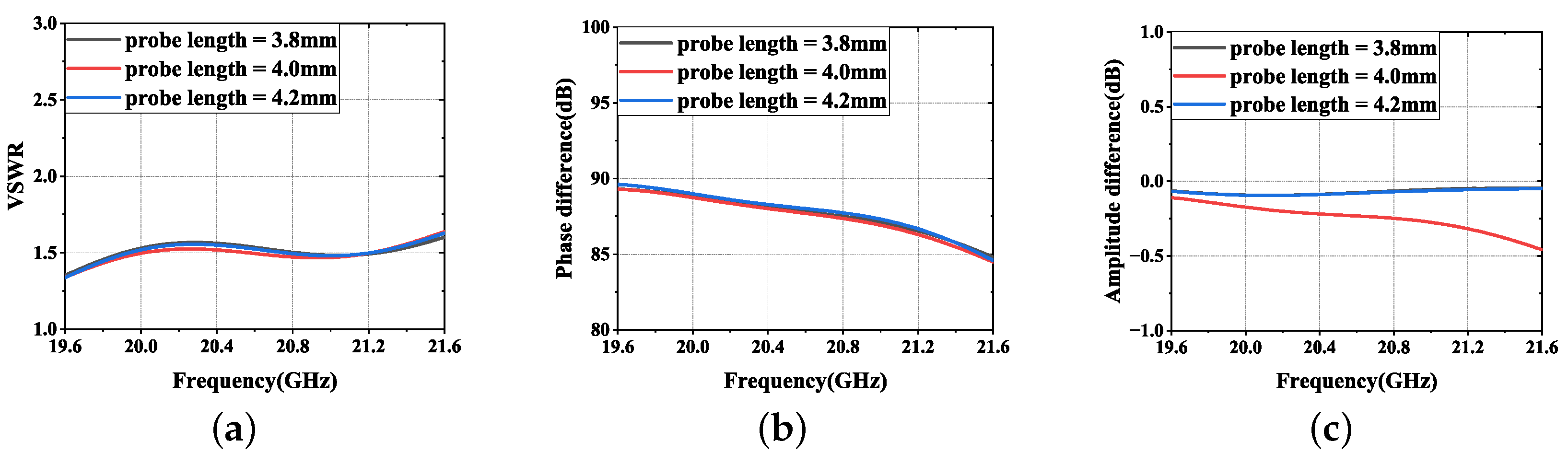
4.1.2. Simulation on the Optimized Coaxial-to-Waveguide Transition

The simulation results of the side-fed coaxial-to-waveguide transition are shown in Figure 13. The simulation results indicate that the optimized transition structure has good performance, with return loss being greater than 20 dB in both the K-band and Ka-band and insertion loss being less than 0.1 dB. Figure 13b provides the electric field distribution inside the waveguide.
Figure 14 shows the simulation results of the performance of the K-band septum polarizer after using the side-fed coaxial-to-waveguide transition, when the probe length varies by ±0.2 mm. It can be seen that at this time, the change in probe length has almost no effect on the performance of the septum polarizer. Therefore, by using the side-fed coaxial-to-waveguide transition, the impact of errors in manufacturing or installation on the performance of the septum polarizer can be effectively reduced.

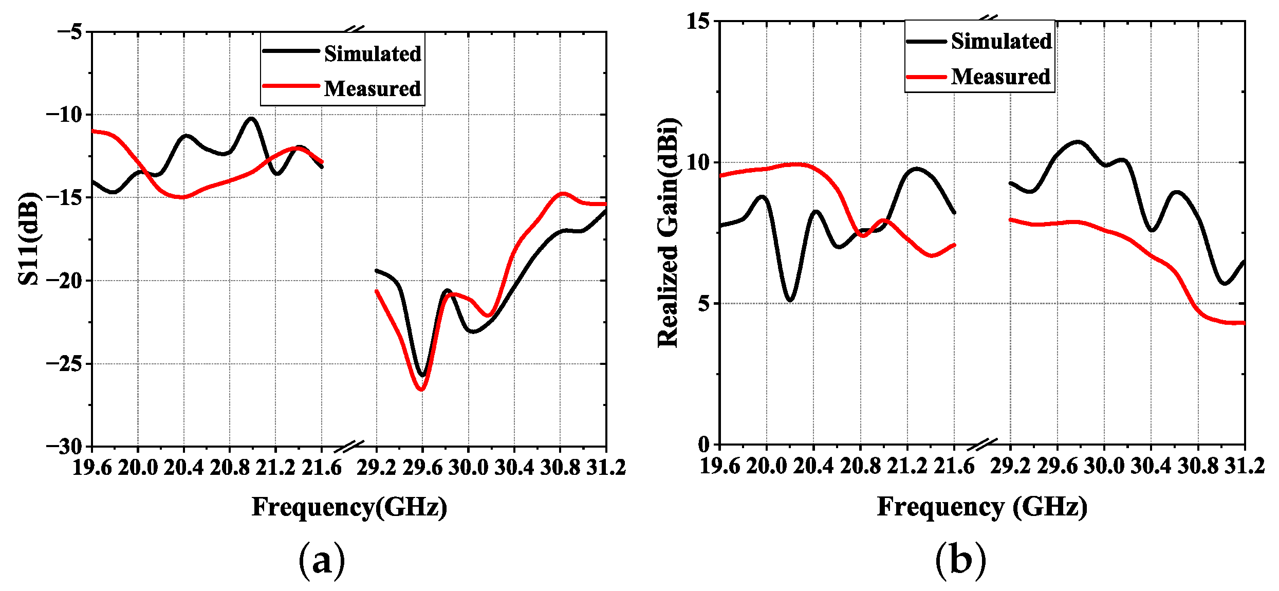
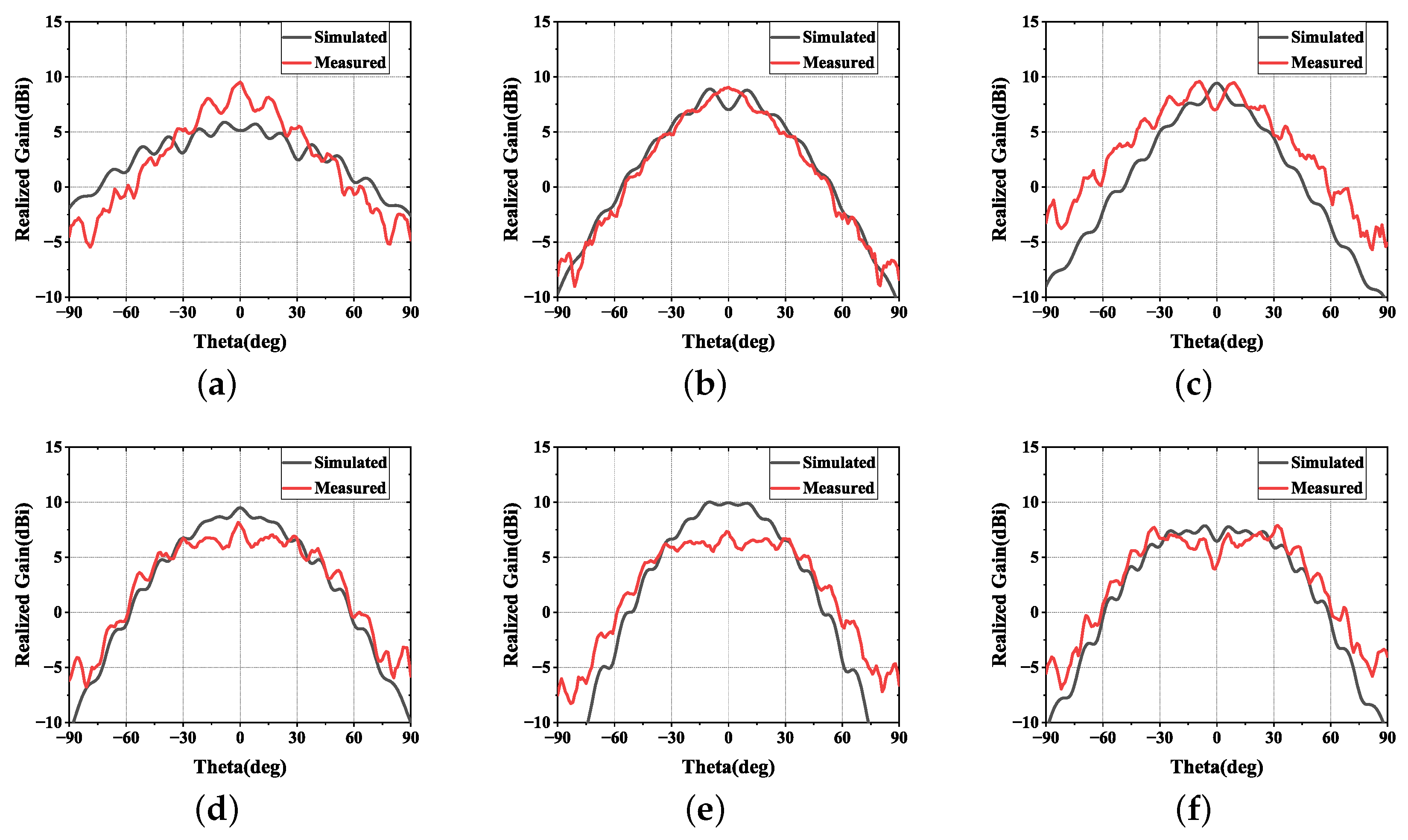
4.2. Test of the Antenna Structure

We conduct extensive simulations and prototype tests on the AcpAS structure to verify its performance. Tests are performed in an anechoic chamber. Due to the symmetry of the antenna structure, the radiation performance of RHCP and LHCP is the same. Figure 15 and Figure 16 provide the simulation and test results of the K-band and Ka-band antennas when radiating RHCP waves, respectively.
From Figure 15 and Figure 16, it is obvious that the simulated and measured results of the antenna are roughly consistent. In the actual testing process, to simulate the scenario of the antenna being mounted on a launch platform, the antenna was installed on a metal plane for testing, which led to a certain error between the test results and the simulation results. In Figure 15a, the return loss of the K-band antenna within the operating frequency band is less than 10 dB, and the Ka-band antenna is less than 15 dB. In Figure 15b, the gain of the K-band antenna within the operating frequency band is greater than 6.7 dBi, and the Ka-band is greater than 4.3 dBi. The return loss and gain performance of the two antennas meet the requirements of the antennas for the airborne relay communication system. Figure 16 provides the simulation and test results of the radiation patterns of the two antennas. Due to the addition of metal edges for installation, ripples and depressions appear in the antenna patterns. In the future, it is possible to consider replacing the metal bottom plate with a dielectric substrate to weaken this effect. From the results, it can be seen that the beam coverage range of both antennas with a gain greater than 0 dBi exceeds ± 55 , featuring wide-beam coverage.

5. Conclusions

This paper analyzes and simulates the optimization of the septum polarizer, improves the feeding structure of the polarizer, and proposes a wide-beam coverage dual-CP antenna based on this. Physical prototypes of two antennas operating in the K-band and Ka-band were fabricated and tested. The simulated and measured results are in good agreement. The results show that the two designed antennas operate from 19.6 GHz to 21.6 GHz and from 29.2 GHz to 31.2 GHz, respectively. The antennas have dual-CP characteristics. The beam widths of the two antennas with gains higher than 0 dBi are greater than ±55°, and the radiation patterns exhibit good symmetry. This indicates that the two antennas are a good choice for a lift-off relay communication system. Subsequently, the designed antennas will be mounted on an unmanned helicopter and communication experiments will be conducted to verify the actual performance of the antennas.

Author Contributions

Conceptualization, X.M.; methodology, X.M. and S.H.; validation, X.M.; formal analysis, S.H. and G.Y. investigation, T.G.; resources, S.H. and Q.F.; writing—original draft preparation, X.M. and S.H.; writing—review and editing, S.H. and G.Y.; supervision, G.Y. and S.H.; project administration, G.Y.; funding acquisition, S.H. All authors have read and agreed to the published version of the manuscript.

Funding

This work was supported in part by the Research Program of National University of Defense Technology under Grant No. ZK23-58 and in part by the National Natural Science Foundation of China under Grant No. 62402510.

Institutional Review Board Statement

Not applicable.

Informed Consent Statement

Not applicable.

Data Availability Statement

The original contributions presented in the study are included in the article; further inquiries can be directed to the first author.

Conflicts of Interest

The authors declare no conflicts of interest.

References

  1. Peng, W.; Li, M.; Li, Y.; Gao, W.; Jiang, T. Ultra-dense heterogeneous relay networks: A non-uniform traffic hotspot case. IEEE Netw. 2017, 31, 22–27. [Google Scholar] [CrossRef]
  2. Ran, Y. Considerations and suggestions on improvement of communication network disaster countermeasures after the Wenchuan Earthquake. IEEE Commun. Mag. 2011, 49, 44–47. [Google Scholar] [CrossRef]
  3. Seng, S.; Yang, G.; Li, X.; Ji, H.; Luo, C. Energy-efficient communications in unmanned aerial relaying systems. IEEE Trans. Netw. Sci. Eng. 2021, 8, 2780–2791. [Google Scholar] [CrossRef]
  4. Yin, S.; Zhao, Y.; Li, L.; Yu, F.R. UAV-assisted cooperative communications with time-sharing information and power transfer. IEEE Trans. Veh. Technol. 2020, 69, 1554–1567. [Google Scholar] [CrossRef]
  5. Li, B.; Fei, Z.; Zhang, Y. UAV communications for 5G and beyond: Recent advances and future trends. IEEE Internet Things J. 2019, 6, 2241–2263. [Google Scholar] [CrossRef]
  6. Zhang, S.; Liu, J. Analysis and optimization of multiple unmanned aerial vehicle-assisted communications in post-disaster areas. IEEE Trans. Veh. Technol. 2018, 67, 12049–12060. [Google Scholar] [CrossRef]
  7. Seng, S.; Luo, C.; Li, X.; Ji, H. Stable Communications in Green Unmanned Aerial Relaying Systems. IEEE Internet Things J. 2023, 10, 16675–16685. [Google Scholar] [CrossRef]
  8. Gómez, L.; Ibrahim, A.S. Design, Analysis and Simulation of Microstrip Antenna Arrays with Flexible Substrate in Different Frequency, for Use in UAV-Assisted Marine Communications. J. Mar. Sci. Eng. 2023, 11, 730. [Google Scholar] [CrossRef]
  9. Li, M.; Shang, Z.; Pu, L.; Tang, M.; Zhu, L. Low-Profile, Low Sidelobe Array Antenna with Ultrawide Beam Coverage for UAV Communication. Chin. J. Aeronaut. 2024; in press. [Google Scholar]
  10. He, C.; Xie, Z.; Bian, D.; Zhong, X. Study of interference localization using single satellite based on signal strength distribution in multi-beam antenna for satellite communications system. Int. J. Distrib. Sens. Netw. 2018, 14, 61–71. [Google Scholar] [CrossRef]
  11. Li, H.; Huang, Y.; Chu, J.; Liu, X.; Wu, C.; Li, D. Research on Inter-satellite and Satellite-Ground Communication Based on Multi-beam-Phased-Array Antenna. Commun. Signal Process. Syst. 2019, 515, 134–141. [Google Scholar]
  12. Lee, H.; Kim, Y.; Lee, H.L. Reconfigurable Antenna for UAV-Assisted Wide Coverage Air-to-Ground Communications. IEEE Access 2022, 10, 1. [Google Scholar] [CrossRef]
  13. Adomnite, C.; Lesanu, C.; Done, A.; Yu, A.; Dimian, M.; Lavric, A. The Design and Implementation of a Phased Antenna Array System for LEO Satellite Communications. Sensors 2024, 24, 1915. [Google Scholar] [CrossRef] [PubMed]
  14. Nikulin, A.V.; Kosmynin, A.N.; Burtsev, V.D.; Prokhorov, S.Y.; Vosheva, T.S.; Filonov, D.S. Towards phased array antenna operating in Ku-band for satellite communications. Photonics Nanostructures Fundam. Appl. 2024, 58, 101216. [Google Scholar] [CrossRef]
  15. Yang, Y.H.; Sun, B.H.; Guo, J.L. A Low-Cost, Single-Layer, Dual Circularly Polarized Antenna for Millimeter-Wave Applications. IEEE Antennas Wirel. Propag. Lett. 2019, 18, 651–655. [Google Scholar] [CrossRef]
  16. Chakrabarti, S. Composite feed dual circularly polarized microstrip antenna with improved characteristics. Microw. Opt. Technol. Lett. 2016, 58, 283–289. [Google Scholar] [CrossRef]
  17. Zhu, W.; Xiao, S.; Yuan, R.; Tang, M. Broadband and dual circularly polarized patch antenna with H-shaped aperture. In Proceedings of the 2014 International Symposium on Antennas and Propagation Conference Proceedings, Kaohsiung, Taiwan, 2–5 December 2014; pp. 549–550. [Google Scholar]
  18. Ibrahim, K.M.; Hassan, W.M.; Abdallah, E.A.; Attiya, A.M. Wideband sequential feeding network for Ku-band dual circularly polarized 4 × 4 antenna array. Int. J. RF Microw. Comput.-Aided Eng. 2020, 30, 1–12. [Google Scholar] [CrossRef]
  19. Gao, K.; Ding, X.X.; Gu, L.; Zhao, Y.W.; Nie, Z.P. A broadband dual circularly polarized shared-aperture antenna array using characteristic mode analysis for 5G applications. Int. J. RF Microw. Comput.-Aided Eng. 2021, 31, 1–10. [Google Scholar] [CrossRef]
  20. Chen, Q.; Zhang, H.; Yang, L.C.; Li, H.P.; Zhong, T.; Min, X.L.; Tan, S.L. Novel dual-band asymmetric U-shaped slot antenna for dual-circular polarization. Int. J. RF Microw. Comput.-Aided Eng. 2017, 27, e21047. [Google Scholar] [CrossRef]
  21. Xu, L.; Lu, W.L.; Yuan, C.Y.; Zhu, L. Dual circularly polarized loop antenna using a pair of resonant even-modes. Int. J. RF Microw. Comput.-Aided Eng. 2019, 29, e21703. [Google Scholar] [CrossRef]
  22. Wei, C.; Zhou, M.; Ding, K.; Yu, F.X.; Mo, J.J.; Zhao, X.L. Compact wideband dual circularly polarized L-shaped slot antenna. Microw Opt. Technol. Lett. 2018, 60, 1685–1691. [Google Scholar] [CrossRef]
  23. Xu, R.; Li, J.Y.; Liu, J.; Zhou, S.G.; Wei, K.; Xing, Z.J. A simple design of compact dual-wideband square slot antenna with dual-sense circularly polarized radiation for WLAN/Wi-fi communications. IEEE Transac. Antennas Propag. 2018, 66, 4884–4889. [Google Scholar] [CrossRef]
  24. Saini, R.K.; Dwari, S. A broadband dual circularly polarized square slot antenna. IEEE Transac. Antennas Propag. 2016, 64, 290–294. [Google Scholar] [CrossRef]
  25. Qi, J.; Han, C.; Lin, S.; Qiu, J. Dual circularly polarized broadband CPW-fed square slot antenna with two L-shape strips. In Proceedings of the 2014 IEEE Antennas and Propagation Society International Symposium (APSURSI), Memphis, TN, USA, 6–12 July 2014; pp. 1722–1723. [Google Scholar]
  26. Saini, R.K.; Dwari, S.; Mandal, M.K. CPW-fed dual-band dual-sense circularly polarized monopole antenna. IEEE Antennas Wirel Propag. Lett. 2017, 16, 2497–2500. [Google Scholar] [CrossRef]
  27. Chandu, D.S.; Karthikeyan, S.S. A novel broadband dual circularly polarized microstrip-fed monopole antenna. IEEE Transac. Antennas Propag. 2017, 65, 1410–1415. [Google Scholar]
  28. Liu, Y.; Cheng, Y.J.; Zhao, M.-H.; Fan, Y. Dual-band shared-aperture high-efficiency reflectarray antenna based on structure-reuse technique. IEEE Antennas Wirel. Propag. Lett. 2021, 20, 366–370. [Google Scholar] [CrossRef]
  29. Tong, X.; Jiang, Z.H.; Li, Y.; Wu, F.; Sauleau, R.; Hong, W. Dual-wideband dual-circularly-polarized shared-aperture reflectarrays with a single functional substrate for K-/Ka-band applications. IEEE Trans. Antennas Propag. 2022, 70, 5404–5417. [Google Scholar] [CrossRef]
  30. Abdollahvand, M.; Forooraghi, K.; Encinar, J.A.; Atlasbaf, Z.; Martinez-de-Rioja, E. A 20/30 GHz reflectarray backed by FSS for shared aperture Ku/Ka-band satellite communication antennas. IEEE Antennas Wirel. Propag. Lett. 2020, 19, 566–570. [Google Scholar] [CrossRef]
  31. Deng, R.; Xu, S.; Yang, F.; Li, M. An FSS-backed Ku/Ka quad-band reflectarray antenna for satellite communications. IEEE Trans. Antennas Propag. 2018, 66, 4353–4358. [Google Scholar] [CrossRef]
  32. Cai, Y.M.; Li, K.; Li, W.; Gao, S.; Yin, Y.; Zhao, L.; Hu, W. Dual-band circularly polarized transmitarray with single linearly polarized feed. IEEE Trans. Antennas Propag. 2020, 68, 5015–5020. [Google Scholar] [CrossRef]
  33. Mei, P.; Zhang, S.; Pedersen, G.F. A dual-polarized and high-gain X-/Ka-band shared-aperture antenna with high aperture reuse efficiency. IEEE Trans. Antennas Propag. 2021, 69, 1334–1344. [Google Scholar] [CrossRef]
  34. Zhu, J.; Yang, Y.; Hou, Z.; Liao, S.; Xue, Q. Dual-band aperture-shared high gain antenna for millimeter-wave multi-beam and sub-6 GHz communication applications. IEEE Trans. Antennas Propag. 2022, 70, 4848–4853. [Google Scholar] [CrossRef]
  35. Guo, Z.J.; Hao, Z.C.; Yin, H.Y.; Sun, D.M.; Luo, G.Q. Planar-shared-aperture array antenna with a high isolation for millimeter-wave low Earth orbit satellite communication system. IEEE Trans. Antennas Propag. 2021, 69, 7582–7592. [Google Scholar] [CrossRef]
  36. Zhang, J.D.; Wu, W.; Fang, D.G. Dual-band and dual-circularly-polarized shared-aperture array antennas with single-layer substrate. IEEE Trans. Antennas Propag. 2016, 64, 109–116. [Google Scholar] [CrossRef]
  37. Bruns, C.; Leuchtmann, P.; Vahldieck, R. Analysis and simulation of a 1–18 GHz broadband double-ridged horn antenna. IEEE Trans. Electromagn. Compat. 2003, 45, 55–60. [Google Scholar]
  38. Tan, C.Y.; Selvan, K.T. Simulation study of a 4–28 GHz double ridged conical horn antenna. In Proceedings of the 2008 IEEE International RF and Microwave Conference, Kuala Lumpur, Malaysia, 2–4 December 2008; pp. 298–301. [Google Scholar]
  39. Mallahzadeh, A.R.; Imani, A. Double ridged antenna for wideband application. Prog. Electromagn. Res. 2009, 91, 273–285. [Google Scholar] [CrossRef]
  40. Jazani, G.; Pirhadi, A. Design of dual-polarised (RHCP/LHCP) quad-ridged horn antenna with wideband septum polariser waveguide feed. IET Microwaves Antennas Propag. 2018, 12, 1541–1545. [Google Scholar] [CrossRef]
  41. Han, K.K.; Wei, G.; Lei, S.Y.; Qiu, C.L.; Qiu, T.C. A design of broadband dual circularly polarized antenna. Int. J. RF Microw. Comput.-Aided Eng. 2021, 31, 1–8. [Google Scholar] [CrossRef]
  42. Bornemann, J.; Labay, V.A. Ridge waveguide polarizer with finite and stepped-thickness septum. IEEE Trans. Microw. Theory Tech. 1995, 43, 1782–1787. [Google Scholar] [CrossRef]
  43. Ege, T.; McAndrew, P. Analysis of Stepped Septum Polarizers. Electron. Lett. 1985, 21, 1166–1168. [Google Scholar] [CrossRef]
  44. Levy, R.; Hendrick, L.W. Analysis and synthesis of in-line coaxial-to-waveguide adapters. In Proceedings of the 2002 IEEE MTT-S International Microwave Symposium Digest, Seattle, WA, USA, 2–7 June 2002. [Google Scholar]
  45. Durga, M.; Tomar, S.; Singh, S.; Suthar, L. Millimeter wave in-line coaxial-to-rectangular waveguide transition. In Proceedings of the 2011 IEEE Applied Electromagnetics Conference (AEMC), Kolkata, India, 18–22 December 2011; pp. 1–3. [Google Scholar]
  46. Pozar, D.M. Microwave Engineering; Wiley: Hoboken, NJ, USA, 2008. [Google Scholar]
Figure 1. Antenna structure of AcpAS.
Applsci 14 09041 g001
Figure 2. Septum polarizer.
Applsci 14 09041 g002
Figure 3. Field pattern structure of the septum polarizer.
Applsci 14 09041 g003
Figure 4. The impact of probe length on the performance of the septum polarizer by direct insertion method. (a) VSWR. (b) Phase difference. (c) Amplitude difference.
Applsci 14 09041 g004
Figure 5. In-line coaxial-to-waveguide transition.
Applsci 14 09041 g005
Figure 6. Side-fed coaxial-to-waveguide transition.
Applsci 14 09041 g006
Figure 7. Photograph of the fabricated prototype of the proposed antennas.
Applsci 14 09041 g007
Figure 8. Schematic diagram of the septum polarizer structure. (a) Side view of septum circular polarizer. (b) Front view of septum circular polarizer.
Applsci 14 09041 g008
Figure 9. Diagram of RHCP electric field vector. (a) t = 0 . (b) t = T / 4 . (c) t = T / 2 . (d) t = 3 T / 4 .
Applsci 14 09041 g009
Figure 10. Diagram of LHCP electric field vector. (a) t = 0 . (b) t = T / 4 . (c) t = T / 2 . (d) t = 3 T / 4 .
Applsci 14 09041 g010
Figure 11. Simulation results of the VSWR, port isolation, phase difference, and amplitude difference for the K-band septum polarizer. (a) VSWR and isolation. (b) Phase difference and amplitude difference.
Applsci 14 09041 g011
Figure 12. Simulation results of the VSWR, port isolation, phase difference, and amplitude difference for the Ka-band septum polarizer. (a) VSWR and isolation. (b) Phase difference and amplitude difference.
Applsci 14 09041 g012
Figure 13. Coaxial-to-waveguide transition simulation results. (a) S parameter. (b) Electric field distribution in waveguide (K-band).
Applsci 14 09041 g013
Figure 14. The impact of the probe length on the performance of the septum circular polarizer by side-fed coaxial-to-waveguide transition. (a) VSWR. (b) Phase difference. (c) Amplitude difference.
Applsci 14 09041 g014
Figure 15. Simulated and measured antenna return loss and gain. (a) Return loss. (b) Realized gain.
Applsci 14 09041 g015
Figure 16. Simulated and measured gains and patterns: (a) 19.6 GHz; (b) 20.6 GHz; (c) 21.6 GHz; (d) 29.2 GHz; (e) 30.2 GHz; (f) 31.2 GHz.
Applsci 14 09041 g016
Table 1. Parameters of the coaxial-waveguide transition structure (mm).
h 1 h 2 h 3 l 1 l 2 l 3
K-band2.61.81.12.82.12.6
Ka-band21.30.562.61.92.2
Table 2. Length Parameters of the K/Ka-band septum polarizer (mm).
Length Para.adL l 0 l 1 l 2 l 3 l 4 l 5 a 1 a 2 a 3 a 4 a 5
K-band8.5134.8216.021.512.292.652.381.057.1442.222.010.24
Ka-band6.35760.522.87.861.192.062.582.251.865.062.992.231.120.62
Disclaimer/Publisher’s Note: The statements, opinions and data contained in all publications are solely those of the individual author(s) and contributor(s) and not of MDPI and/or the editor(s). MDPI and/or the editor(s) disclaim responsibility for any injury to people or property resulting from any ideas, methods, instructions or products referred to in the content.

