Article

Fabrication and Performance Evaluation of a Directly Immersed Photovoltaic-Thermal Concentrator for Building Integration

by
Alberto Riverola
,
Daniel Chemisana
*,
Álex Moreno
,
Chrysovalantou Lamnatou
and
Alejandro Solans
Department of Chemistry, Physics and Environmental and Soil Sciences, University of Lleida, Jaume II 69, 25001 Lleida, Spain
*
Author to whom correspondence should be addressed.
Appl. Sci. 2024, 14(19), 9086; https://doi.org/10.3390/app14199086
Submission received: 4 August 2024 / Revised: 23 September 2024 / Accepted: 3 October 2024 / Published: 8 October 2024
(This article belongs to the Section Optics and Lasers)

Abstract

:
A novel concentrating photovoltaic-thermal solar collector was designed, fabricated and experimentally investigated at the University of Lleida, in Spain. Two designs based on two dielectric liquids, isopropyl alcohol (IPA) and deionised water (DIW), were developed. In both cases, the solar cells were directly liquid-immersed. The study includes experiments and numerical simulations. The proposed concentrator was incorporated into a testing unit to examine its potential as a façade by controlling light and thermal flux transmitted into a building. The results show promising electrical performance and acceptable thermal performance, with thermal losses ranging from 14 to 20 W °C−1m−2. The optical efficiency was around 73% in the case of the concentrator with DIW and about 76% for the one with IPA. Regarding electrical performance, the fill factors for IPA and DIW configurations are as follows: 62.8% and 61.7%, respectively. The comparison results reveal striking differences between the testing unit with and without solar concentrators, with the concentrator-equipped unit showing around four times lower illuminance and a 50% reduction in maximum heat fluxes and interior temperature. Generally speaking, it can be said that these energy-generating façades show satisfactory behaviour and offer interesting possibilities for building-integrated applications.

1. Introduction

A considerable amount of energy is consumed in buildings; this sector is responsible for 40% of total energy consumption and 36% of the greenhouse-gas emissions in the European Union [1]. These numbers are expected to increase further due to the growing use of energy-intensive devices, efforts to expand energy access in developing countries, the prevalence of coal-fired power plants, etc. [2]. However, there is a proven potential to increase energy independence and reduce greenhouse gas emissions by adopting strategies such as energetically efficient buildings, renovations, energy performance standards, and measuring the embodied carbon of buildings, as emphasised by the European Commission’s Energy Performance of Buildings Directive, which aims to double the retrofitting rate of existing buildings and enhance energy efficiency to support climate neutrality and energy independence goals [3]. On the basis of data from the EEA (European Environment Agency), it is important to attain climate neutrality in the EU by 2050 [4]. To this end, zero-energy buildings and renewable energy technologies play a pivotal role.
A technology that successfully addresses the requirements mentioned above by generating “green” energy in an efficient way is known as building-integrated solar technology [5,6,7]. These systems are designed to integrate seamlessly with building structures, providing renewable energy in situ while contributing to the architectural design and sustainability in buildings. Various types of building-integrated solar systems exist, each offering distinct advantages (from an energetic point of view as well as from an environmental point of view). For example, photovoltaic (PV) modules can be incorporated into roofs, facades and windows by means of semi-transparent PV modules/systems, enhancing both functionality and aesthetics, and offering eco-friendly solutions for buildings, greenhouses, etc. By way of illustration, Peng et al. [8] investigated dot-matrix patterned photovoltaic (PV) modules for building integration, underlining the importance of building-integrated PV systems due to the high energy conversion efficiency and the aesthetic versatility. The use of the smallest possible dot size was presented as a solution to cope with the problem of losses.
Bearing in mind that space availability is a limiting factor in buildings, hybrid photovoltaic–thermal (PVT) collectors stand out due to their interesting geometrical and architectural characteristics (e.g., in the case of building-integrated applications [9]) and on-site cogeneration of electricity and heat with global efficiencies of around 70% (with an electrical efficiency about 20% and thermal efficiency around 50%) [10]. In addition to this, PVT systems occupy less space than conventional solar energy systems (i.e., PV modules and solar thermal collectors), which produce the same amount of energy using separate devices for production of electricity and thermal energy [10]. Furthermore, PVT technologies offer numerous options (active systems; passive systems, etc.) for various applications in the building sector [11].
On the other hand, PVT systems can reduce cost and environmental impacts while increasing the efficiency by using solar concentration, known as concentrating photovoltaic–thermal (CPVT) systems. In this case, expensive solar cell material is partly replaced with lower-cost optical elements, concentrating light onto a smaller area [5,6,7].
Nonetheless, effective temperature management is crucial since the energy flux received by the cells is proportional to the concentration ratio, and high cell temperatures may cause considerable efficiency losses, depending on the PV technology [5].
In this regard, there are different cooling strategies, active or passive [12,13,14,15,16], but among them, direct immersion of PV cells in dielectric liquids offers additional advantages. PV-cell efficiency is enhanced due to a reduction in Fresnel losses (compared to a bare PV cell). Moreover, better temperature control can be achieved since the thermal contact resistance between PV cell and dissipater is notably reduced or even eliminated [17,18,19]. It is worth mentioning that by carefully selecting dielectric liquids with the right optical properties, these liquids can act as selective absorptive filters, providing effective spectral selection. Specifically, these liquids absorb solar frequencies outside the spectral response bandwidth of the selected PV-cell technology before they reach the solar cell, thereby preventing potential overheating while allowing the useful part of the solar spectrum to pass through. Consequently, dielectric liquids could serve as both optical filters and heat transfer fluids, aiming towards efficient CPVT systems [20,21]. Xin et al. [22] investigated liquid-immersed PV cells (dimethyl silicone oil) with high concentration ratios. The proposed system was compared with other configurations without liquid immersion, and promising experimental results were obtained, but it was noted that more experimental studies are needed. The electrical characteristics of GaInP/GaInAs/Ge triple-junction PV cells immersed in liquid (dimethyl silicone oil) were investigated (500×; 25 °C). Wang et al. [23] studied silicon-based solar cells immersed in liquids. The option “bare solar cells immersed in non-polar silicone oil” presented the best performance, showing good stability. Zhu et al. [24] proposed a liquid-immersion cooling method for densely packed PV cells and high concentration ratios. PV-panel cooling to below 45 °C was experimentally achieved. Dimethyl silicone oil was selected, taking into account factors such as high-temperature resistance and exposure to UV light. Moreover, Zhu et al. [25] investigated PV cells with water-immersion cooling. The proposed system included a dish concentrator (250×), tracking and deionised water for cooling. Degradation in module performance appeared after three days and was attributed to either the low ion concentration or the electrolytic reaction at the solar cell connections. On the other hand, the temperature distribution of the panel was rather uniform.
A limited number of investigations where the fluids act as both thermal absorbers (CPVT) and optical filters have been conducted. Otanicar et al. [26] developed a CPVT collector (14×) with an electrical efficiency of 4% and a peak thermal efficiency of 61%, where the nanoparticle-based receiver used polydimethylsiloxane-based oil because of its optical properties. Mojumder et al. [27] studied five commercial fluids, concluding that Therminol®VP1 achieved the highest PV efficiency of 16.39% (10×), and fluid viscosity had the most significant impact on increasing the bulk fluid temperature.
The results of the works cited above are promising, but none of these studies addressed the direct immersion of solar cells, and the proposed systems based on this cooling technique were not optimised for building integration [28,29,30,31]. Recently published review articles [31,32,33,34,35] also show that there is a dearth of studies on CPV/CPVT liquid-immersion-cooling systems optimised for building-integrated applications.
Considering the above-mentioned research gaps, an innovative system was developed and tested at the University of Lleida in Spain, proposing directly immersed PVTs, especially CPVTs, with optical efficiencies above 76% and configurations suitable for building-integrated applications [36]. With the proposed system, we aimed to substitute ordinary sun-tracking window blinds that control the amount of light entering the building with a photovoltaic-thermal collector, which, instead of blocking the direct light, converts it into electricity and heat. Sun tracking was achieved by rotation in a similar way to standard blinds, plus minor movement to control the distance between the cylinders, which allowed lighting control. In order to assess the performance of the developed solar system [36] in the case of façade-integrated applications, dynamic energy performance simulations were conducted [37]. The aim was to determine the feasibility of the proposed system in terms of covering the energy demands of a two-storey house in three different locations: Lisbon (Portugal), Barcelona (Spain) and Genoa (Italy). The solar fractions achieved showed a satisfactory performance, proving the relevance of the proposed system in relation to the goals pursued [37]. This research is a big step forward because it is quite difficult to have as a starting point a small-scale laboratory system, laboratory-scale fabrication, modelling and simulations, with the aim of developing a prototype of realistic dimensions. Testing a system under real conditions gives rise to challenges, and, in addition to this, drawbacks are identified and the feasibility of the proposed system is determined.
To sum up, the literature on CPVT shows that there are numerical and laboratory-scale studies on these technologies, but there are very few experimental studies on novel CPVT systems with direct immersion. In order to fill this scientific gap and considering the importance of PV technologies for high [38] and low [39,40] concentration applications, the present study aims to perform the following:
  • Experimentally evaluate the performance of a façade-integrated CPVT system under real operating conditions (the experimental set-up was built according to the required dimensions: intermediate-size system).
  • Evaluate a PV-cell cooling technique that has not been extensively studied.
  • Provide valuable information about CPVT modules, prototypes of realistic dimensions and innovative building-integrated solar concentrators, contributing to the enrichment of the literature on CPVT technologies.
  • Examine the performance of a system and its assembly that have been designed considering an appropriate control strategy for tracking solar altitude.
  • Monitor the performance of the proposed system in terms of electrical and thermal energy production.
  • Assessment of the qualitative performance of the façade-integrated system in terms of illumination and thermal envelope performances.
The article is structured as follows: Section 2 covers system design; Section 3 is about construction and assembly process; in Section 4, the experimental results are provided; and in Section 5, the main results are explained.

2. Design of the System
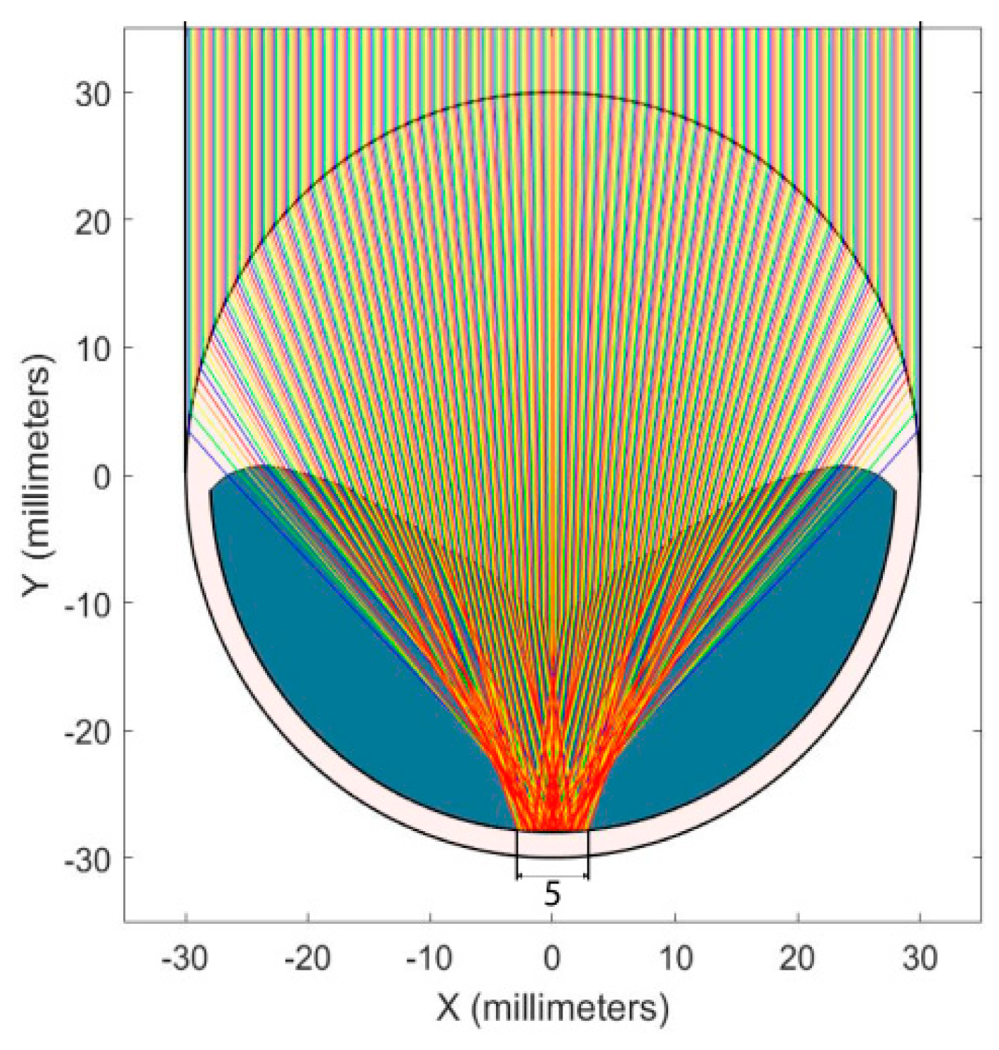
2.1. Optical Design

The optical system was based on a combination of two optical elements that concentrated the incident solar irradiance onto a linear-focus receiver. Figure 1 illustrates the cross-section of the two designed optical systems. The first element, where the rays initially arrive in Figure 1, had two different surfaces, one on the exterior and the other in the interior. The external one was a half cylinder, and the internal one was a free-from non-transverse profile surface that was optimised as a function of the inner liquid. The second element was a dielectric liquid (coloured in blue in Figure 1) that filled the cavity formed between the solid internal surface of the first optical element and a cylindrical transparent casing. In other words, from the outside, the optical system looked like a cylindrical rod. The cylindrical casing was made of polymethyl methacrylate (PMMA), and there were two configurations: one had the cylinders filled with deionised water (DIW) and the other with isopropyl alcohol (IPA). In the next subsection, the motivation to choose these two liquids is explained.
The design requirements of the optical system are as follows (further details about the whole design process can be found in reference [36]):
  • To focus the incident solar irradiance onto the PV receiver, the optical efficiency and geometric concentration ratio must be maximised while minimising chromatic aberration and maintaining focal length inside the cavity.
  • The acceptance angle has to be high enough so that the system is able to use low-accuracy (cheap) solar trackers. In this way, the PV cells are cooled down by direct immersion in the optical liquid medium. The free-form profile of the solid optical element was optimised by means of a genetic algorithm. The goal was to meet the requirements previously mentioned, considering PMMA casing and the two selected dielectric liquids.
In Table 1, the main optical parameters obtained in the optical study are shown. The geometric concentration ratio (Cg, the quotient between aperture area and PV-cell area) of the design was 12, and the optical efficiency (ηo, relation between the power reaching the PVs and the incident power) was 76% for DIW and a bit higher in the case of IPA (80%). The non-uniformity parameter (α), calculated as the quotient between the maximum difference of local irradiances at the receiver plane and the sum of the maximum and minimum local irradiances, indicates a higher degree of non-uniformity in the case of IPA (α = 0.22), but 0.22 is considered to be an acceptable α value.

2.2. Thermal and Electrical Design

The thermal design of the collector had some particular features since the heat exchange/cooling system aimed to have a double function: (1) offering PV-cell cooling and (2) acting as a thermal collector (collecting the heat removed). In addition, the coolant acted as an optical element in conjunction with the PMMA cylindrical casing, focusing incident rays onto the PV cells. To this end, the thermal fluid needed to have the following:
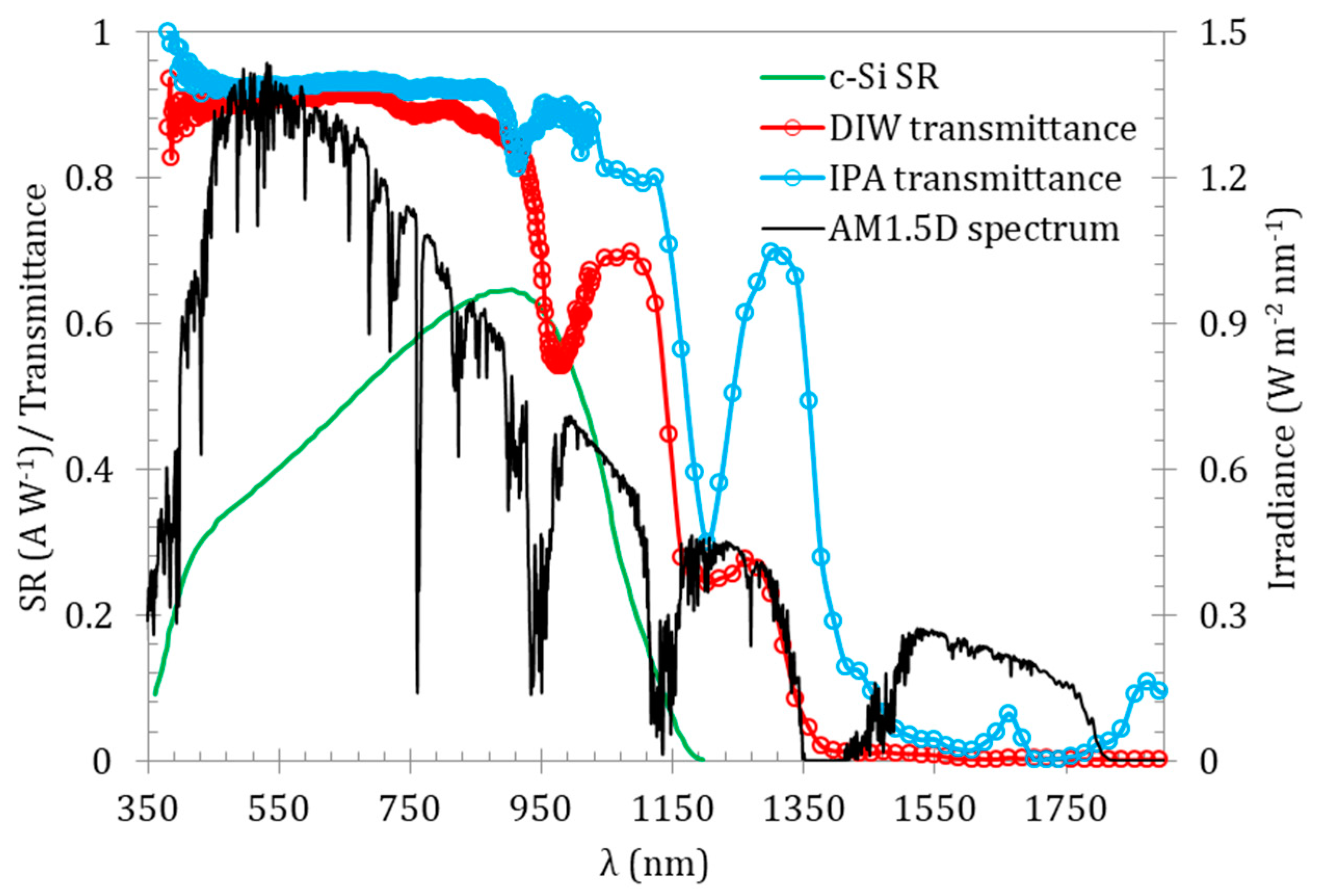
  • High light transmission so as to optimise electrical output (considering the effective spectrum of the PV cells).
  • High absorption in the spectral range where the PV cells do not generate electricity in order to achieve effective heat dissipation, optimising thermal production.
  • The necessary characteristics to act as a coolant:
    • High specific heat and thermal conductivity to maximise thermal exchange.
    • Low coefficient of expansion to prevent the increase in pressure in the hydraulic circuit when temperature increases.
    • Appropriate range of operating temperatures, taking into account melting and boiling points as well as real operating conditions.
    • High density and low viscosity so that the system can maximise heat-removal capacity and attain low pressure losses in pumping.
    • The materials should be available and not expensive.
On the basis of a previous study that analysed several liquids for directly immersed PVT concentrators [20], two liquids with characteristics that meet the requirements previously described are the following: DIW and IPA. In Figure 2, the spectral-transmittance curves of both liquids are illustrated. It can be noticed that these liquids have high transmittance of photons in the frequency range in which silicon-based PV cells operate and absorb all the photons for wavelengths longer than 1400 nm. It should also be noted that these liquids present two drawbacks: (1) DIW freezing-temperature limits can be easily exceeded (this problem can be solved by mixing DIW and IPA), and (2) IPA degrades some polymeric compounds, and this means that it was necessary to select IPA-resistant materials for module fabrication.
The thermal design was related to the previous optical design. The resulting liquid/cavity geometries (one for the DIW configuration and the other for the IPA one) were those optimising the optical requirements.
On the basis of these cavity geometries, computational fluid dynamics (CFD) analysis was carried out in Comsol Multiphysics to determine the following: (1) the optimum geometry/position of the inlet/outlet ducts and (2) the velocity that minimised pressure losses while enhancing thermal exchange with the cells (previous study: [37]).
Figure 3 shows the plots of representative temperature contours for both configurations. Longitudinal and cross-sectional views are presented. It can be observed that due to the shape of the IPA cavity, the PV-cell area was a bit warmer than in the case of DIW. On the other hand, the greater proportion of PMMA solid body was more efficient in isolating the system from the exterior. It can be noted that the inlet was located at the bottom part of the cavity and the outlet was located on the top, in agreement with the flow lines/path traced by the liquid. The flow lines were obtained by means of multiphysics simulations, combining fluid mechanics and energy equations.
In terms of the electrical production, according to the design, every module was formed by 6 cells connected in series (length: 12 cm; width: 0.5 cm each one). The PV cells utilised were commercial passivated emitter rear cells (PERCs) by SAS [42], adapted to the requirements of the geometry by laser cutting. In Table 2, the main electrical characteristics of the PV cells are shown. Voc is the open-circuit potential, Jsc stands for the short-circuit current density, FF is the fill factor, η is the mean electrical efficiency of the cells and γ is the power temperature coefficient.

2.3. Mechanical and Control Design

As a first step, the geometries of the optical elements were designed. These components were fixed to the sides (only). Furthermore, the design was affected by the weight of the fluid and the solid casing. Considering these parameters, the maximum possible length was determined. In this case, the safety factor (relation between the load that a system can withstand before failure to the actual applied load) was not the most critical parameter, since small deformations may have led to optical aberrations, and defocusing that would reduce optical efficiency. For this reason, the maximum allowable deformation (bending) was limited to 3 mm for achieving a satisfactory concentrated spot based on the optical-simulation results. For deformations above 3 mm, the optical performance begins to be negatively affected. Figure 4 illustrates the maximum deformation as a function of concentrator length (the length ranges from 1 to 4 m). It can be seen that the maximum length of the concentrator should not exceed 2.5 m (in this case, the deformation was 3 mm).
The present study was conducted considering an assembly comprising concentrating elements whose numbers ranged from 8 to 32. Figure 5 shows the 8-element configuration (Figure 5a), the displacement with respect to the initial position (Figure 5b) and details of the connecting rods, the lateral covering of the optical element and the supporting axle with a block piece to avoid displacement of the connecting rods along the length of the axle (Figure 5c). The diameter of the axle was found to be critical in terms of concentrator bending, being necessary to maintain a diameter of 2 cm in order to obtain a maximum displacement of 3 mm. The thicknesses of the connecting rods ranged from 2 to 4 mm, depending on the number of concentrating elements. In both cases (connecting rods; axle), standard stainless steel was used.
As a first step, the dimensions were determined based upon the mechanical study. As a second step, the drivers to achieve solar altitude tracking were designed and incorporated into the model. Two types of mechanisms were necessary. The first one was a mechanical spindle system that controlled the distance between the subunits of the collector (subunits = the individual concentrating elements) using a “scissor” configuration. The second one was a system that drove the rotation of the modules so that their aperture plane tracked apparent solar altitude movement, using a linear actuator and a pivot. Both mechanisms were automatically guided by a comparator based on two photoresistors and a shading element that continuously acquired values required by an Arduino Mega® device. The system adequately focused sunlight when the two photoresistor signals were equal; otherwise, the shading element resulted in two signals that were different. The control programme had one loop (the first one) based on astronomical ephemeris (clock on the Arduino board) and another loop (the second one = precision loop) associated with the comparison of the analogue readings of the photoresistors. The control programme also included some loops that allowed manual control of the motors that drove the mechanisms.
For this study, and due to practicality in construction and suitability for testing, the prototype included 8 concentrating elements, each 1 m long. Under these conditions, the mechanical features were less restrictive (taking into account the limitations related to the maximum bending of 3 mm) and the requirements could be fulfilled with a 2 mm thick connecting-rod and an axle with a diameter of 8 mm.

3. Construction and Assembly

The fabrication comprised several phases from the manufacturing of the optical elements to the fabrication of the structure, the mechanical components and the tracking electronic control. In the following subsections, details are given.

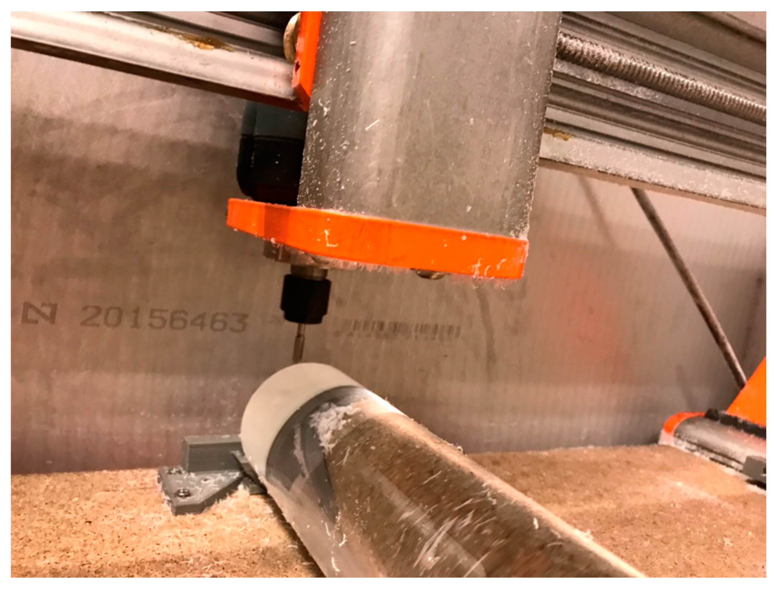
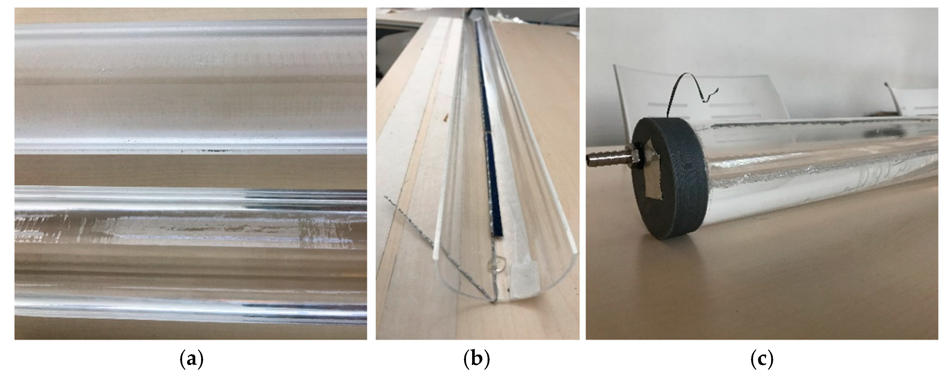
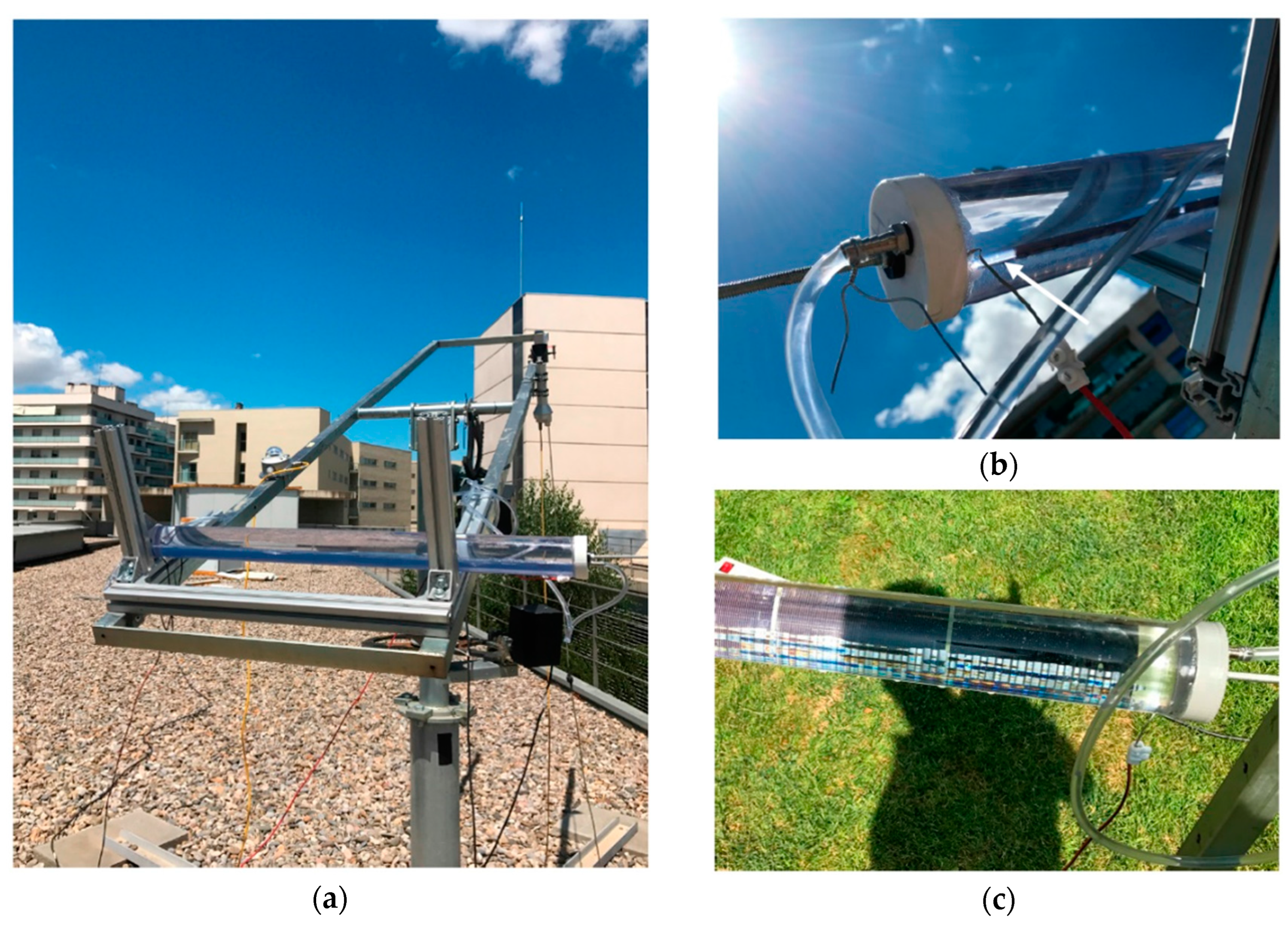
3.1. Module Fabrication

The production of the concentrating elements of the system that combined two dielectric media was arduous, because it is quite difficult to move from prototypes of several centimetres developed for optical validation to machining elements of 1 m long. The operations of roughing and subsequent polishing required a special code for the numerical controller to obtain the expected results. Each module needed a continuous machining process of about 60 h, but this time could be significantly reduced through serial production methods such as extrusion or moulding.
The machining process is shown in Figure 6. As can be seen, special holders and tools were designed and 3D-printed. The goal was to attach the components to the cylinder and achieve a length of 1 m.
All the cells were cut into pieces of the following dimensions: length 12 cm; width 6.5 mm (5 mm active area plus 1.5 mm busbar). The cutting process was performed by a pulsed Nd:YAG laser. Each cylinder was composed of six cells connected in series with copper-based ribbon wires.
The final stage was to assemble all the individual elements in order to build each individual module. In Figure 7a, details of the solid concentrating element before and after polishing are shown. In Figure 7b, the casing where the PV module was attached can be seen. Finally, in Figure 7c, the assembled concentrator as well as the solid optical element, the PV module, the lateral covers and the hydraulic circuit connector are illustrated. As it has been previously indicated, each module consisted of eight identical concentrators.

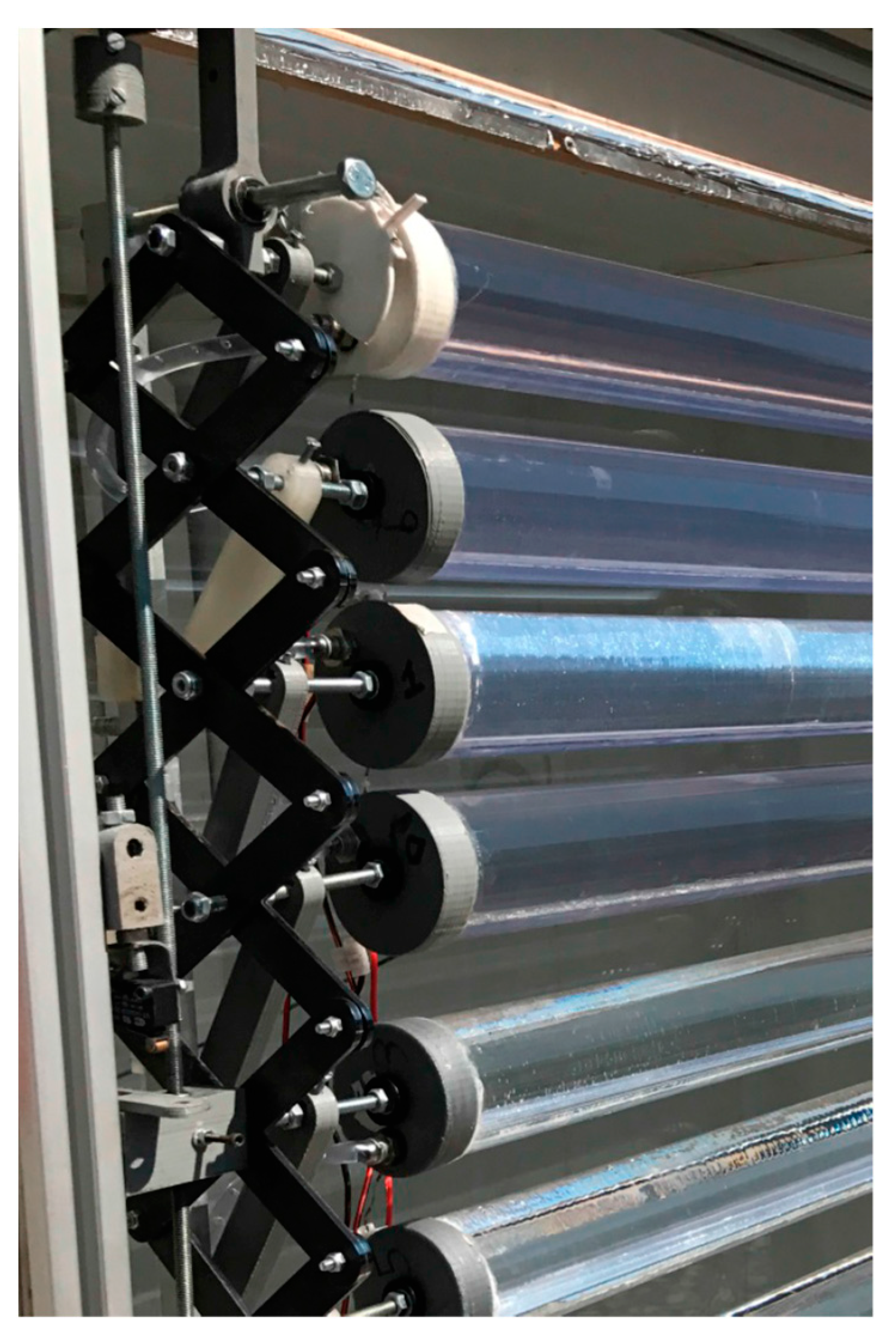
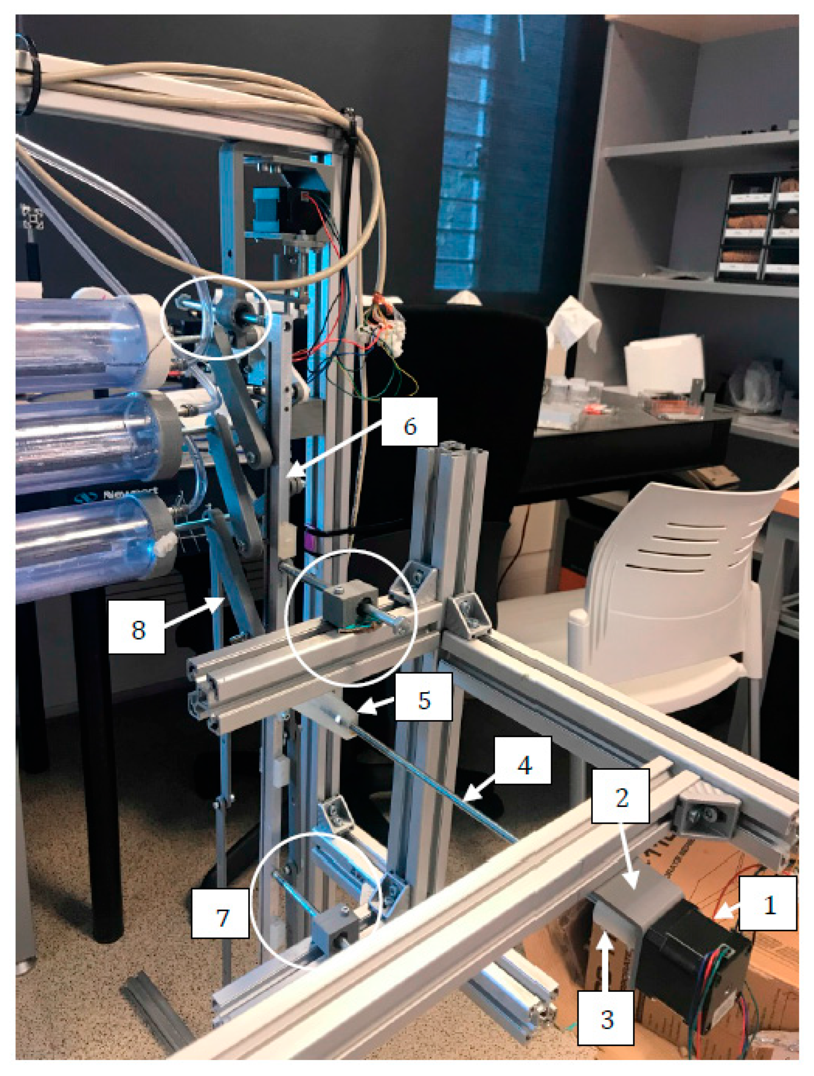
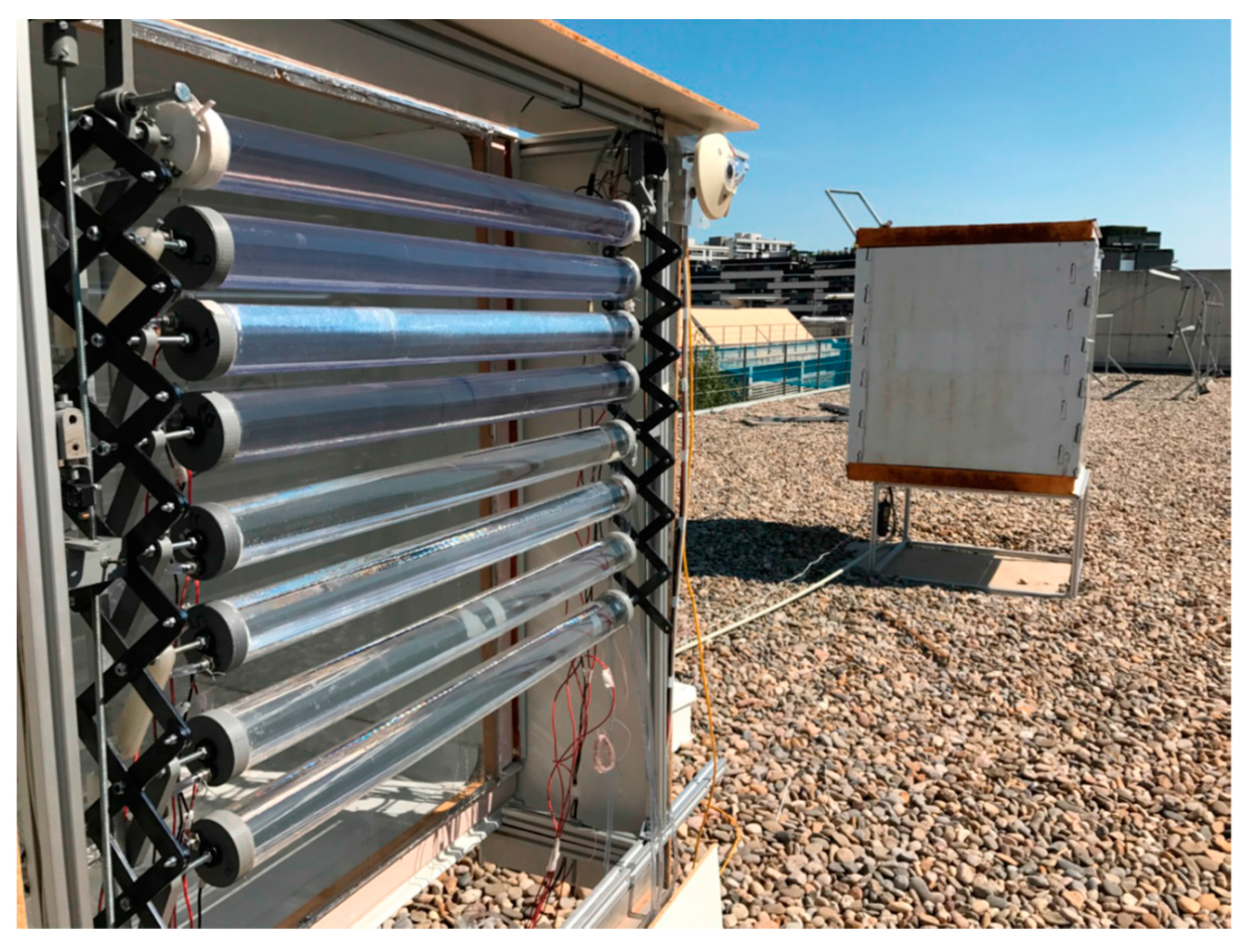
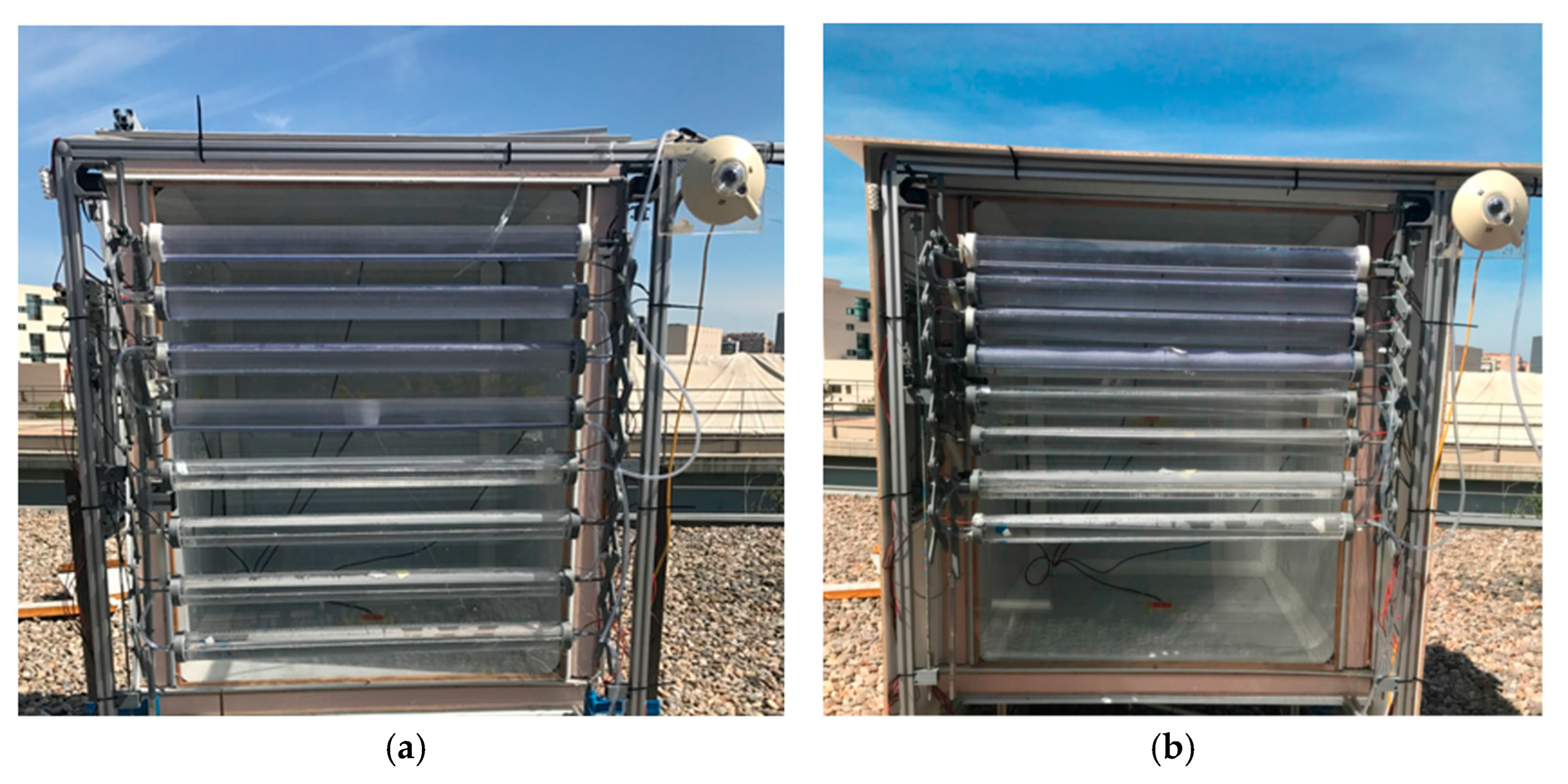
3.2. Fabrication of the Other Elements and Final Assembly

Figure 8 shows the final prototype: details of the mechanisms are given in Figure 8b and those of the corresponding CAD image in Figure 8a. The frame (exterior structure) was made of extruded aluminium and had a cross-sectional area of 30 × 30 mm2. It is also worth noting that the mechanical spindle system (“scissor” configuration) was located on the left of the prototype. Furthermore, it is important to note that there were two additional components: the motor holder and the motor axis adapter. All these elements were first designed and then 3D-printed.
Figure 9 shows details of the scissor-mechanism rods that allow separating or approaching the individual concentrators. A 3D-printed white component located at the edge of the top concentrator that had the two photoresistors mentioned above for solar-tracking purposes and a shading element can be seen.
Figure 10 shows all parts of the proposed system that produced the rotation of the concentrators to track the solar altitude. The motor holder structure was attached to the main frame, and there were different options to hold the motor in place. It is important to note that this prototype did not have the final dimensions and will be further optimised to reduce the space occupied. From right to left, the first element of Figure 10 is the motor (component no. 1). This was a stepper motor similar to the one utilised for the translational motion produced by RS (model 892-8732). The motor was fixed to the structure by means of a square printed PLA (polylactic acid) (Figure 10: no. 2). The motor shaft and the spindle were coupled by means of a PLA-printed element, white in colour (Figure 10: no. 3). The spindle consisted of a metric six-threaded rod (Figure 10: no. 4). The component no. 5 (Figure 10) is the nut support of the spindle nut mechanism. Figure 10 shows how the piece printed in PLA houses the nut. This piece was joined by four screws and was connected to an aluminium guide (Figure 10: no. 6). The guide groove was fabricated using the previously mentioned numerical control machine. In order to guarantee that the movement produced by the nut spindle mechanism was equally transmitted to each part of the guide, three support elements were incorporated. These components are indicated by circles (Figure 10: no. 7). Two of them were fixed to the extruded-aluminium components. More specifically, a bolt was threaded into the guide and fixed by means of a piece printed in PLA (grey in colour) that housed a linear bearing. When testing the movement, unwanted movement was observed. To cope with this problem, a third bolt was added. This bolt was fixed to the frame by means of a piece printed in PLA (grey in colour) with a linear bearing. Lastly, the elements no. 8 (Figure 10) are the eccentric connecting rods that connected the guide with the axle of the cylinders and caused rotation. These components were made of grey PLA, and the axle (or pivot) that moved in the guide had a bolt. This configuration minimised friction related to movement. Additionally, the guide was lubricated with graphite powder.

4. Experimental Investigation

Experiments were carried out at the Applied Energy Research Centre (CREA) at the University of Lleida (Spain), which is located in Lleida (latitude 41.36° N and longitude 0.37° E).
The experimental phase comprised different stages, ranging from individual characterisation of the concentrator elements to system characterisation. Three photographs of the characterisation of one of the concentrators are included in Figure 11. Figure 11a illustrates the concentrator that was mounted on a two-axis solar tracker so that solar irradiance was always perpendicular to the PV-cell plane. The tracker was equipped with a pyranometer (Kipp & Zonen CMP6, Delft, the Netherlands) and a pyrheliometer (Kipp & Zonen CHP1, Delft, the Netherlands) to measure global and direct irradiance, respectively. Figure 11b shows details of the hydraulic connection and the concentrated spot (indicated by an arrow). Also, in Figure 11c, the concentration effect and the optimised module are shown. The 5 mm cell optically increased to 60 mm.
After checking the performance of the 8 concentrator units to ensure their correct operation, these components were mounted on the structure described in the previous section.
The system, with a gross aperture area of approximately 1 × 1 m2 and 8 concentrator modules (4 modules with DIW circulating in series through all of them and 4 modules with IPA in a similar way), was installed on a specially built testing unit. The system was monitored and the thermal/electrical characteristics were obtained. Its effect on the temperature/illumination in the interior space of the testing unit was examined. In order to investigate the behaviour of the proposed system, taking into account building integration and the effect of the system on the interior temperature and illumination, two testing units were built. These testing units had the same dimensions and materials—1 × 1 × 1 m3 cubes with all the walls made of prefabricated sandwich panels of 10 cm thickness—except the one oriented to the south (in this case, a sheet of methacrylate (8 mm thickness) was used). Both testing units (Figure 12) were oriented to the south. Moreover, both testing units were placed 50 cm above the ground to minimise the albedo effect. It should also be mentioned that the differential thermal and illumination effects in the interior space were evaluated.
As can be seen in Figure 13, a pyranometer (Kipp&Zonen CMP6) was placed in the vertical plane of the modules in order to register the proper global irradiance received. Furthermore, each module had T-type thermocouples at the inlet/outlet and on the rear surface of the PV PERC solar cells [42] located at the half-length of the module. Both units were equipped with flux meters (Hukseflux HFP01, Delft, the Netherlands) on each wall, except for the one where the element to be tested was located. A luxmeter (PCE-174, Tobarra, Spain) was placed in the centre of each testing unit. In addition, a T-type thermocouple was suspended from the ceiling (in the centre of the air volume). The thermocouple had a reflective shielding element to avoid the influence of incident irradiance and monitor the interior air temperature. The IV curves were measured with a source meter (Keithley 2460, Cleveland, OH, USA), and all the data were stored in a datalogger (Campbell Sci. CR3000, Leicestershire, United Kingdom). Finally, there were two liquid-holding tanks: one was filled with IPA, and the other was filled with DIW. The circulation of the two liquids was maintained by two precision peristaltic pumps (Heidolph, Schwabach, Germany) at 0.0018 kg/s.

5. Results

Both units (TU1 and TU2) were tested prior to the installation of the concentrator system in one of the units. Heat flux through all the walls (except the south-facing walls) and the interior temperature were monitored. It was found that both configurations exhibited satisfactory behaviour, resulting in almost identical heat fluxes and temperature values. Figure 14 shows, as an example, the values that were recorded over three days. Different weather conditions (sunny and cloudy days) were examined.
Therefore, as a first step, the testing units were characterised. As a second step, the concentrators were installed. As described in Section 4, one unit included the concentrator and glazing (8 mm PMMA) and the other unit had PMMA glazing only and is considered the reference case. Both glazing elements were south-facing. Figure 15 clearly depicts the benefits of the unit with the concentrating system. The results show that, in this case, the temperatures registered are less subjected to daily-temperature and irradiance variations, achieving temperature and flux values quantitatively lower than those of the reference unit. In addition to the shading effect, the modules located on the outer face of the transparent construction may improve the isolation of the interior space when the exterior temperature is lower.
Furthermore, numerical and experimental stationary thermal characteristic curves were determined for both concentrator configurations (DIW and IPA). As can be seen in Figure 16, the heat-loss coefficients are high: the values range from around 14 to 20 W °C−1m−2 (experimental and simulated wind velocity is 2 m/s). This is attributed to the fact that the solar collector morphology (glazing) was optimised for concentrating the incident irradiance but not for minimising heat losses. These losses could be reduced by embedding vacuum layers into the system with minor design changes, but the fabrication of such systems could not be conducted at the available facilities. Good agreement between experimental and numerical values was obtained. Minor discrepancies are mainly attributed to wind speed fluctuations around the value of 2 m/s (steady-state experiments).
In Figure 17, the average IV (electric current–voltage) curves of DIW and IPA modules can be seen. As shown in Figure 17, these curves were obtained under similar direct-irradiance conditions (around 965 Wm−2). Furthermore, the temperatures were controlled. More specifically, the temperatures were maintained close to 25 °C (26.4 °C for the DIW option; 26.8 °C for the IPA option). The FF was found to be 62.8% in the case of the IPA configuration and 61.7% in the case of the DIW one. The values of DIW were lower (comparing to those of IPA) but relatively close, as expected. It should be noted that negative impacts on Voc and especially on the FF, compared to the original cell, were observed. These effects are attributed to the following facts: (1) a reduction in the parallel resistance due to edge shunts and higher recombination rate, (2) an increased series resistance due to the six cells connected in series and (3) the limitation of maximum current by the most damaged cell in the series connection [43]. On the basis of these IV curves, the module average electrical power output was calculated. In both cases, a value of approximately 5.15 W was found. In addition, the experimental optical efficiency can be derived from the IV curves and the aforementioned electrical data by comparing the short-circuit current densities. The optical efficiency for DIW is 73%, and for IPA, 76%. As in our previous study for the optical design, the differences with the theoretical results are attributed to manufacturing inaccuracies [36].
Finally, in both cases (TU1 and TU2), a characterisation of the interior lighting was conducted. The goal was to quantify the differential effects (1) from a thermal point of view and (2) in terms of illuminance. Figure 18 shows an example of the difference in lux. These values were registered in the centre of the floor (of both testing units; from solar noon). It can be noted that the illuminance of the testing unit with the concentrator is around four times smaller than the one registered in the reference testing unit. It can also be seen that at 15 h solar time, the luxmeter was shaded by the west wall (shading begins at 15 h solar time). It is worth mentioning that the concentrating system, which has been assessed in terms of illuminance at the optimum position of the modules to prevent shading and offer lighting control, could increase the quantity of light entering the testing unit. In this case, a set value of the desired illuminance level should be established. To this end, the modules should be placed further apart to allow more light to enter. Taking this into account, the estimated g-value ranges from 0.3 to 0.6 depending on the sun’s position (the azimuth remains untracked) and the distance between the modules. The CPVT system effectively blocks the direct solar irradiance when the space between the modules is set to the minimum to avoid shading between them but allows diffuse light to pass through the space between collectors unaltered. Also, a fraction of the diffuse light can pass through the collectors and reach the window. In this case, solar fractions around 0.3, depending on the solar position, can be expected. On the other hand, increasing the space between the collectors allows a tuneable amount of direct irradiance to be transmitted towards the windows and could lead to g-values of up to 0.6.

6. Conclusions

A photovoltaic–thermal concentrator was designed, fabricated and experimentally tested at the University of Lleida, in Spain. The proposed solar system is suitable for façade-integrated applications, aiming to substitute ordinary sun-tracking window blinds with a CPVT system that converts the direct light, and its main innovation lies in the use of liquids (IPA or DIW) as part of the optical element. This study includes experiments and numerical simulations. The results demonstrate the following:
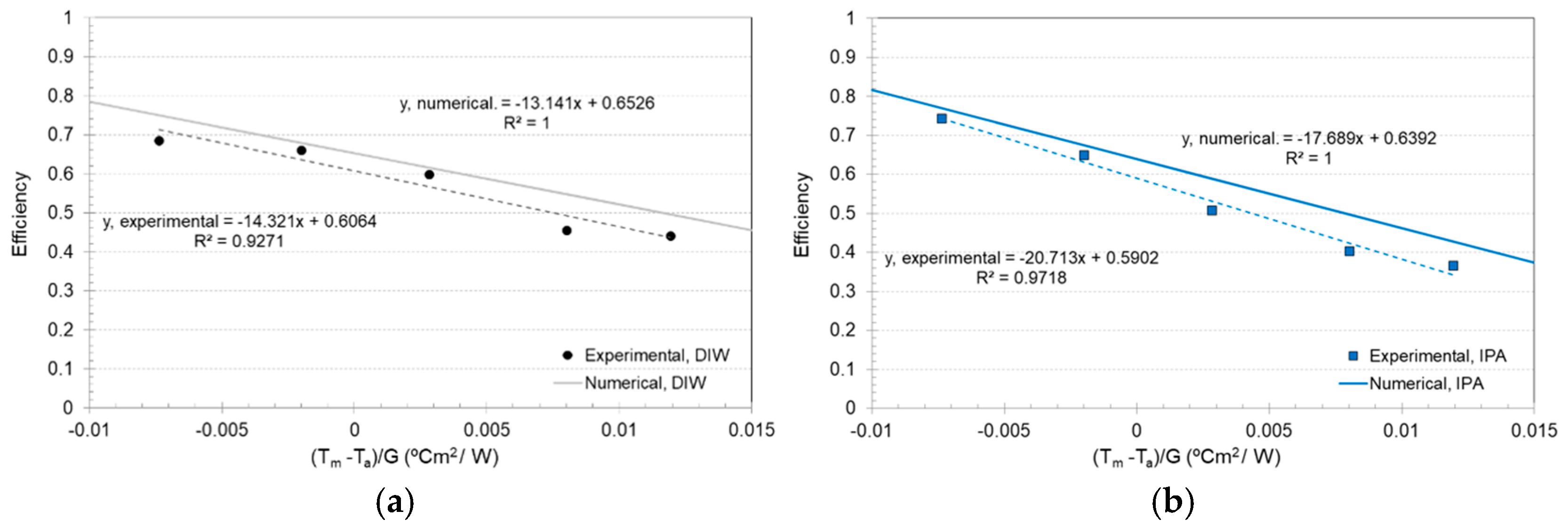
  • There is a good agreement between experimental and numerical values regarding optical performance and thermal behaviour.
  • The experimental optical efficiency is around 73% for the concentrator with DIW and about 76% for the one with IPA, close to the simulation results (76% for DIW and 81% for IPA).
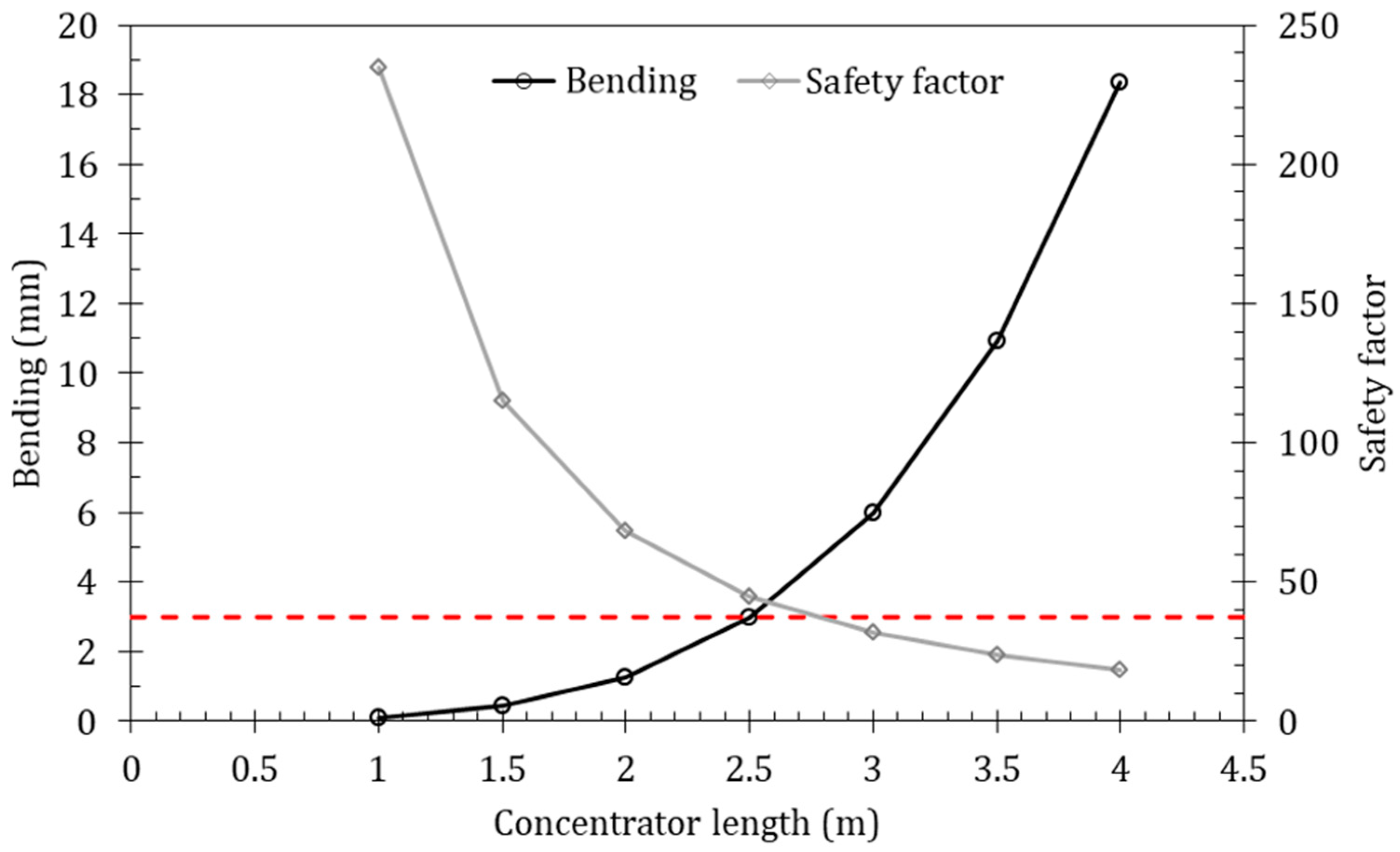
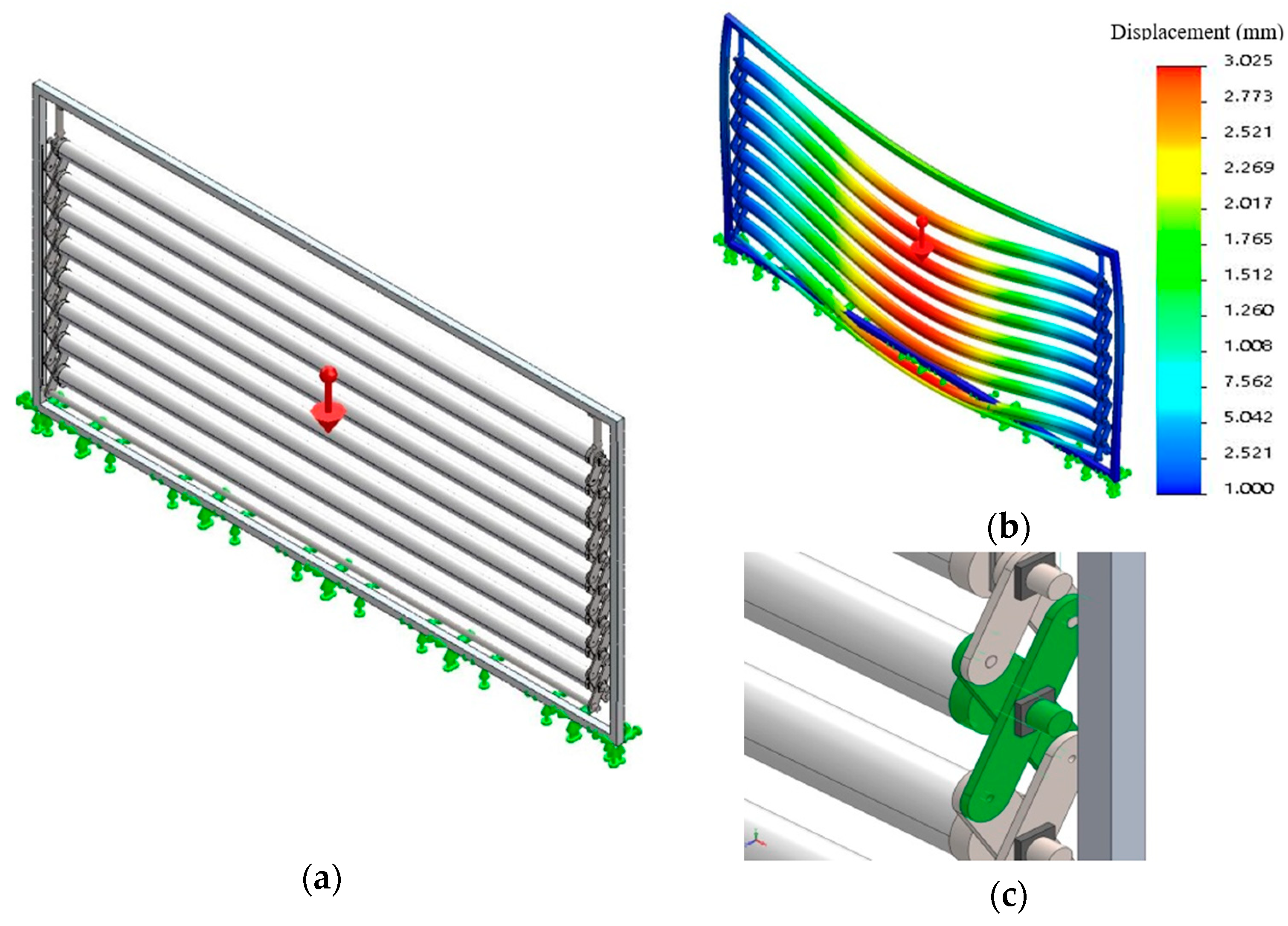
  • Module bending is a limiting factor because it can cause important efficiency losses.
  • The thermal losses of both configurations range from 14 to 20 W °C−1m−2, indicating that the concentrator is not optimal from a thermal point of view (improvement is needed). The results also agree with the simulations, which showed losses ranging from 13 to 18 W °C−1m−2.
  • Regarding electrical performance, the fill factors for IPA and DIW are as follows: 62.8% and 61.7%, respectively. The fill-factor reduction is mainly attributed to an increased series resistance due to the interconnection of the PV cells and the micro-short circuits caused by the laser-cutting process.
  • Sun-tracking is a critical factor in developing a successful concentrating solar system.
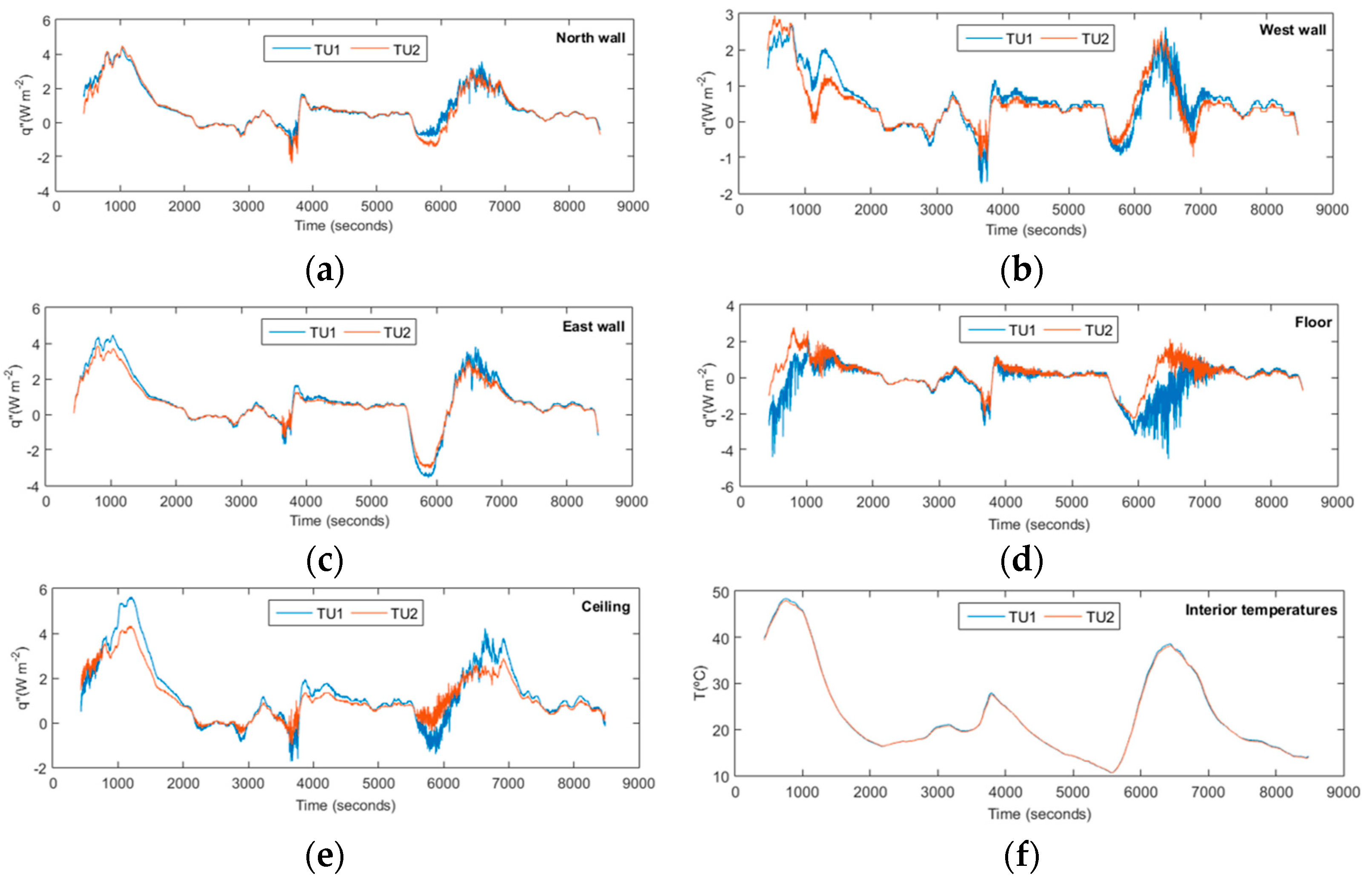
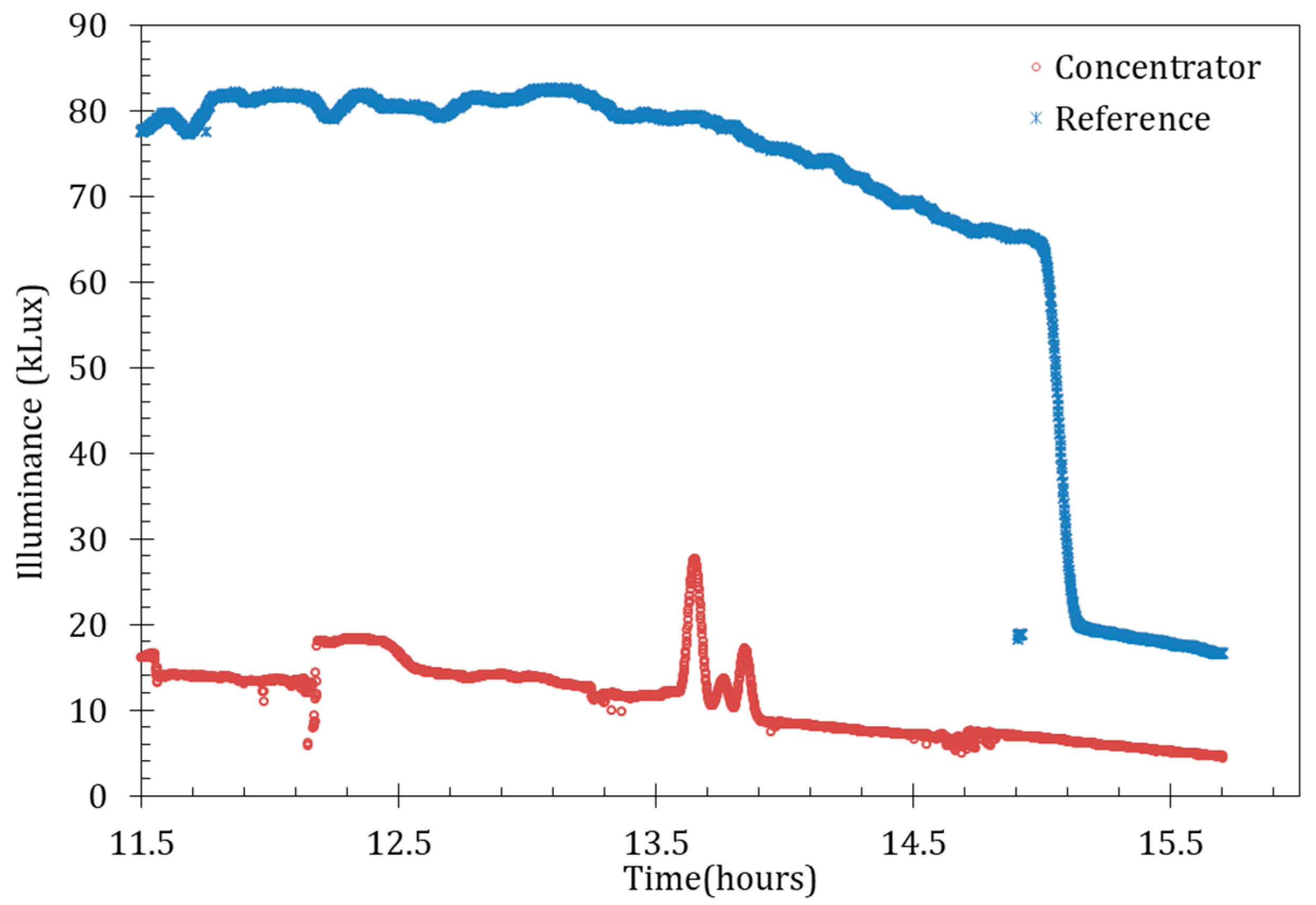
  • There are striking differences between the testing unit without solar concentration and the one with solar concentration. The illuminance in the testing unit with the concentrator is about four times lower than that observed in the reference testing unit (configured with maximum shading for lighting control). Additionally, the maximum heat fluxes through the lateral walls and the ceiling and the interior temperature in the concentrator-equipped unit are reduced by approximately 50%.
Generally speaking, the proposed liquid-based solar systems show satisfactory behaviour and offer promising possibilities for façade-integrated applications. Future research will assess efficiency improvements, multifunctional aspects to become a suitable system for façade integration and develop models to evaluate the life-cycle environmental profiles of the proposed technologies, taking into account different types of environmental indicators.

Author Contributions

Conceptualisation, D.C. and A.R.; methodology, D.C. and A.R.; software, Á.M. and A.S.; validation, A.R., Á.M. and A.S.; formal analysis, D.C. and C.L.; investigation, D.C., A.R. and Á.M.; resources, D.C.; writing—original draft preparation, A.R. and C.L.; writing—review and editing, D.C.; visualisation, A.R.; supervision, D.C.; project administration, D.C.; funding acquisition, D.C. All authors have read and agreed to the published version of the manuscript.

Funding

The authors would like to thank “Ministerio de Ciencia e Innovación” of Spain, MCIN/AEI/10.13039/501100011033 for the funding (grant reference: TED2021-132843B-I00). D. Chemisana thanks Institució Catalana de Recerca i Estudis Avançats (ICREA) for the ICREA Acadèmia award. Furthermore, this research was supported by the Generalitat de Catalunya (2021 SGR 01618). Chr. Lamnatou is an Associate Professor of the Serra Húnter programme.

Institutional Review Board Statement

Not applicable.

Informed Consent Statement

Informed consent was obtained from all subjects involved in the study.

Data Availability Statement

The research data can be provided upon request. Please contact the corresponding author.

Conflicts of Interest

The authors declare no conflicts of interest.

References

  1. ECEEE. Available online: https://www.eceee.org/all-news/news/eu-to-start-measuring-embodied-carbon-emissions-from-buildings/ (accessed on 26 June 2024).
  2. IEA. Available online: https://www.iea.org/reports/world-energy-outlook-2019 (accessed on 5 February 2021).
  3. EPB. Available online: https://epb.center/epb-standards/energy-performance-buildings-directive-epbd/ (accessed on 26 June 2024).
  4. EEA. Available online: https://www.eea.europa.eu/highlights/eu-achieves-20-20-20 (accessed on 26 June 2024).
  5. Chemisana, D. Building Integrated Concentrating Photovoltaics: A review, Renewable and Sustainable. Energy Rev. 2011, 15, 603–611. [Google Scholar]
  6. Lamnatou, C.; Chemisana, D. Photovoltaic/thermal (PVT) systems: A review with emphasis on environmental issues. Renew. Energy 2017, 105, 270–287. [Google Scholar] [CrossRef]
  7. Lamnatou, C.; Chemisana, D. Concentrating solar systems: Life Cycle Assessment (LCA) and environmental issues. Renew. Sustain. Energy Rev. 2017, 78, 916–932. [Google Scholar] [CrossRef]
  8. Peng, D.; Fang, Z.; Yu, X.; Huang, Q. Characteristic analysis of patterned photovoltaic modules for building integration. Energy Convers. Manag. 2023, 276, 116524. [Google Scholar] [CrossRef]
  9. Vassiliades, C.; Agathokleous, R.; Barone, G.; Forzano, C.; Giuzio, G.F.; Palombo, A.; Buonomano, A.; Kalogirou, S. Building integration of active solar energy systems: A review of geometrical and architectural characteristics. Renew. Sustain. Energy Rev. 2022, 164, 112482. [Google Scholar] [CrossRef]
  10. Al-Waeli, A.H.A.; Sopian, K.; Kazem, H.A.; Chaichan, M.T. Photovoltaic/Thermal (PV/T) systems: Status and future prospects. Renew. Sustain. Energy Rev. 2017, 77, 109–130. [Google Scholar] [CrossRef]
  11. Kalogirou, S.A.; Tripanagnostopoulos, Y. Hybrid PV/T solar systems for domestic hot water and electricity production. Energy Convers. Manag. 2006, 47, 3368–3382. [Google Scholar] [CrossRef]
  12. Araki, K.; Uozumi, H.; Yamaguchi, M. A simple passive cooling structure and its heat analysis for 500 X concentrator PV module. In Proceedings of the Conference Record of the Twenty-Ninth IEEE Photovoltaic Specialists Conference, New Orleans, LA, USA, 19–24 May 2002; pp. 1568–1571. [Google Scholar]
  13. Fork, D.K.; Horne, S.J. Passively Cooled Solar Concentrating Photovoltaic Device. U.S. Patent US2007/0256724 A1, 8 November 2007. [Google Scholar]
  14. Coventry, J.S. Performance of a concentrating photovoltaic/thermal solar collector. Sol. Energy 2005, 78, 211–222. [Google Scholar] [CrossRef]
  15. Liu, L.; Zhu, L.; Wang, Y.; Huang, Q.; Sun, Y.; Yin, Z. Heat dissipation performance of silicon solar cells by direct dielectric liquid immersion under intensified illuminations. Sol. Energy 2011, 85, 922–930. [Google Scholar] [CrossRef]
  16. Akrouch, M.A.; Chahine, K.; Faraj, J.; Hachem, F.; Castelain, C.; Khaled, M. Advancements in cooling techniques for enhanced efficiency of solar photovoltaic panels: A detailed comprehensive review and innovative classification. Energy Built. Environ. 2023; in press. [Google Scholar] [CrossRef]
  17. Abrahamyan, Y.A.; Serago, V.I.; Aroutiounian, V.M.; Anisimova, I.D.; Stafeev, V.I.; Karamian, G.G.; Martoyan, G.A.; Mouradyan, A.A. The efficiency of solar cells immersed in liquid dielectrics. Sol. Energy Mater. Sol. Cells 2002, 73, 367–375. [Google Scholar] [CrossRef]
  18. Han, X.; Wang, Y.; Zhu, L. Electrical and thermal performance of silicon concentrator solar cells immersed in dielectric liquids. Appl. Energy 2011, 88, 4481–4489. [Google Scholar] [CrossRef]
  19. Abdelrazik, A.S. The potential of liquid-based spectrally-selective optical filtration and its use in hybrid photovoltaic/thermal solar systems. Sol. Energy 2023, 249, 569–605. [Google Scholar] [CrossRef]
  20. Chemisana, D.; Fernandez, E.F.; Riverola, A.; Moreno, A. Fluid-based spectrally selective filters for direct immersed PVT solar systems in building applications. Renew. Energy 2018, 123, 263–272. [Google Scholar] [CrossRef]
  21. Huang, G.; Wang, K.; Markides, C.N. Efficiency limits of concentrating spectral-splitting hybrid photovoltaic-thermal (PV-T) solar collectors and systems. Light Sci. Appl. 2021, 10, 28. [Google Scholar] [CrossRef]
  22. Xin, G.; Wang, Y.; Sun, Y.; Huang, Q.; Zhu, L. Experimental study of liquid-immersion III–V multi-junction solar cells with dimethyl silicon oil under high concentrations. Energy Convers. Manag. 2015, 94, 169–177. [Google Scholar] [CrossRef]
  23. Wang, Y.; Fang, Z.; Zhu, L.; Huang, Q.; Zhang, Y.; Zhang, Z. The performance of silicon solar cells operated in liquids. Appl. Energy 2009, 86, 1037–1042. [Google Scholar] [CrossRef]
  24. Zhu, L.; Wang, Y.; Fang, Z.; Sun, Y.; Huang, Q. An effective heat dissipation method for densely packed solar cell under high concentrations. Sol. Energy Mater. Sol. Cells 2010, 94, 133–140. [Google Scholar] [CrossRef]
  25. Zhu, L.; Boehm, R.F.; Wang, Y.; Halford, C.; Sun, Y. Water immersion cooling of PV cells in a high concentration system. Sol. Energy Mater. Sol. Cells 2011, 95, 538–545. [Google Scholar] [CrossRef]
  26. Otanicar, T.; Dale, J.; Orosz, M.; Brekke, N.; DeJarnette, D.; Tunkara, E.; Roberts, K.; Harikumar, P. Experimental evaluation of a prototype hybrid CPV/T system utilizing a nanoparticle fluid absorber at elevated temperatures. Appl. Energy 2018, 228, 1531–1539. [Google Scholar] [CrossRef]
  27. Mojumder, J.C.; Aminossadati, S.M.; Leonardi, C.R. Numerical analysis of a hybrid SF-CPV/T collector using spectral-filter nanofluids suitable for a high operating temperature range. Renew. Energy 2024, 230, 120735. [Google Scholar] [CrossRef]
  28. Han, X.; Wang, Y.; Zhu, L.; Xiang, H.; Zhang, H. Reliability assessment of silicone coated silicon concentrator solar cells by accelerated aging tests for immersing in de-ionized water. Sol. Energy 2011, 85, 2781–2788. [Google Scholar] [CrossRef]
  29. Ju, X.; Xu, C.; Han, X.; Du, X.; Wei, G.; Yang, Y. A review of the concentrated photovoltaic/thermal (CPVT) hybrid solar systems based on the spectral beam splitting technology. Appl. Energy 2017, 187, 534–563. [Google Scholar] [CrossRef]
  30. Looser, R.; Vivar, M.; Everett, V. Spectral characterisation and long-term performance analysis of various commercial Heat Transfer Fluids (HTF) as Direct-Absorption Filters for CPV-T beam-splitting applications. Appl. Energy 2014, 113, 1496–1511. [Google Scholar] [CrossRef]
  31. Vivar, M.; Everett, V. A review of optical and thermal transfer fluids used for optical adaptation or beam-splitting in concentrating solar systems. Prog. Photovolt. Res. Appl. 2014, 22, 612–633. [Google Scholar] [CrossRef]
  32. Fikri, M.A.; Samykano, M.; Pandey, A.K.; Kadirgama, K.; Kumar, R.R.; Selvaraj, J.; Abd Rahim, N.; Tyagi, V.V.; Sharma, K.; Saidur, R. Recent progresses and challenges in cooling techniques of concentrated photovoltaic thermal system: A review with special treatment on phase change materials (PCMs) based cooling. Sol. Energy Mater. Sol. Cells 2022, 241, 111739. [Google Scholar] [CrossRef]
  33. Jacob, J.; Pandey, A.K.; Abd Rahim, N.; Selvaraj, J.; Samykano, M.; Saidur, R.; Tyagi, V.V. Concentrated Photovoltaic Thermal (CPVT) systems: Recent advancements in clean energy applications, thermal management and storage. J. Energy Storage 2022, 45, 103369. [Google Scholar] [CrossRef]
  34. Papis-Frączek, K.; Sornek, K. A Review on Heat Extraction Devices for CPVT Systems with Active Liquid Cooling. Energies 2022, 15, 6123. [Google Scholar] [CrossRef]
  35. Mariam, E.; Ramasubramanian, B.; Sumedha Reddy, V.; Dalapati, G.K.; Ghosh, S.; Pa, T.S.; Chakrabortty, S.; Motapothula, M.R.; Kumar, A.; Ramakrishna, S.; et al. Emerging trends in cooling technologies for photovoltaic systems. Renew. Sustain. Energy Rev. 2024, 192, 114203. [Google Scholar] [CrossRef]
  36. Riverola, A.; Moreno, A.; Chemisana, D. Performance of a dielectric PVT concentrator for building-façade integration. Opt. Express 2018, 26, A892. [Google Scholar] [CrossRef]
  37. Moreno, A.; Riverola, A.; Chemisana, D. Energetic simulation of a dielectric photovoltaic-thermal concentrator. Sol. Energy 2018, 169, 374–385. [Google Scholar] [CrossRef]
  38. Shanks, K.; Senthilarasu, S.; Mallick, T.K. Optics for concentrating photovoltaics: Trends, limits and opportunities for materials and design. Renew. Sustain. Energy Rev. 2016, 60, 394–407. [Google Scholar] [CrossRef]
  39. Sarmah, N.; Mallick, T.K. Design, fabrication and outdoor performance analysis of a low concentrating photovoltaic system. Sol. Energy 2015, 112, 361–372. [Google Scholar] [CrossRef]
  40. Tripanagnostopoulos, Y.; Chemisana, D.; Rosell, J.I.; Souliotis, M. New CPV Systems with Static Reflectors. AIP Conf. Proc. 2010, 1277, 199–202. [Google Scholar]
  41. ASTM G173-03; Standard Tables for Reference Solar Spectral Irradiances: Direct Normal and Hemispherical on 37° Tilted Surface. Available online: https://www.astm.org/g0173-03r20.html (accessed on 3 March 2022).
  42. SAS Silicon Cells. SR6SKUN 156.75 x 156.75 Monocrystalline Solar Cell 5 Bus Bars 2017. Available online: https://www.saswafer.com/ (accessed on 16 April 2017).
  43. Eiternick, S.; Kaufmann, K.; Schneider, J.; Turek, M. Loss Analysis for Laser Separated Solar Cells. Energy Procedia 2014, 55, 326–330. [Google Scholar] [CrossRef]
Figure 1. Schematic of the optical system design for a 12× geometric concentration with DIW.
Applsci 14 09086 g001
Figure 2. Spectral response (SR) of the utilised crystalline silicon (c-Si) cells. Transmittance of DIW, IPA and AM1.5D solar spectrum [41].
Applsci 14 09086 g002
Figure 3. Temperature-contour slices along the length of the collector (0, 0.5 and 1 m), considering (a) DIW and (b) IPA.
Applsci 14 09086 g003aApplsci 14 09086 g003b
Figure 4. Maximum displacement (bending) and safety factor as a function of the module/concentrator length.
Applsci 14 09086 g004
Figure 5. The system designed for the numerical mechanical analysis (the red arrow indicates the gravity effect): (a) general view, (b) displacement chart and (c) a detailed view of the axle and the connecting rods.
Applsci 14 09086 g005
Figure 6. The machining process of a PMMA cylinder.
Applsci 14 09086 g006
Figure 7. (a) The solid concentrating element before and after polishing; (b) a PV module attached to the second half of the concentrator; (c) an assembled concentrator.
Applsci 14 09086 g007
Figure 8. (a) The designed and (b) the fabricated prototype.
Applsci 14 09086 g008
Figure 9. The mechanical spindle system with the “scissor” configuration.
Applsci 14 09086 g009
Figure 10. Details of the rotation-mechanism elements: components 1–8.
Applsci 14 09086 g010
Figure 11. Characterisation of the modules: (a) A PV module mounted on a two-axis tracker together with a pyrheliometer and a pyranometer for solar radiation measurements, (b) details of the hydraulic connection and the concentrated light, (c) details of the module concentration effect.
Applsci 14 09086 g011
Figure 12. The twin testing units: with concentrators (on the left-hand side); without concentrators (on the right-hand side).
Applsci 14 09086 g012
Figure 13. The concentrating system with the (a) unfolded and (b) folded “scissor” configuration.
Applsci 14 09086 g013
Figure 14. Comparison of heat flux (q) and temperature (T) of the twin testing units (TU1 and TU2): (a) north wall, (b) west wall, (c) east wall, (d) floor, (e) ceiling and (f) interior temperatures.
Applsci 14 09086 g014
Figure 15. Comparison of heat flux (q) and temperature (T) of the twin testing units with concentrator (TU1-Conc and TU2-Ref): (a) north wall, (b) west wall, (c) east wall, (d) floor, (e) ceiling, (f) interior temperatures and (g) weather information.
Applsci 14 09086 g015
Figure 16. Thermal characteristic curves for (a) the DIW configuration and (b) the IPA configuration. Wind velocity = 2 m/s. Tm is the mean fluid temperature. Ta is the ambient air temperature, and G stands for solar irradiation.
Applsci 14 09086 g016
Figure 17. The average IV curves: IPA and DIW modules.
Applsci 14 09086 g017
Figure 18. The illumination profile registered in the two testing units. The time refers to solar time. Concentrator = the testing unit with the concentrating system. Reference = the reference testing unit (without solar concentration).
Applsci 14 09086 g018
Table 1. Optical characteristics of the system.
Cg (×)ηo (%) α = C m a x C m i n C m a x + C m i n (-)
DIW1276.140.05
IPA1280.180.22
Table 2. Parameters of the PV cells [38].
Voc (V)Jsc (mA/cm2)FF (%)η (%)γ (%/°C)
0.66240.1179.8521.1−0.375
Disclaimer/Publisher’s Note: The statements, opinions and data contained in all publications are solely those of the individual author(s) and contributor(s) and not of MDPI and/or the editor(s). MDPI and/or the editor(s) disclaim responsibility for any injury to people or property resulting from any ideas, methods, instructions or products referred to in the content.

