

Alternative Solution for Towing Systems Used in the Automotive Industry


Abstract
:Featured Application
Abstract
1. Introduction
2. Models and Methods
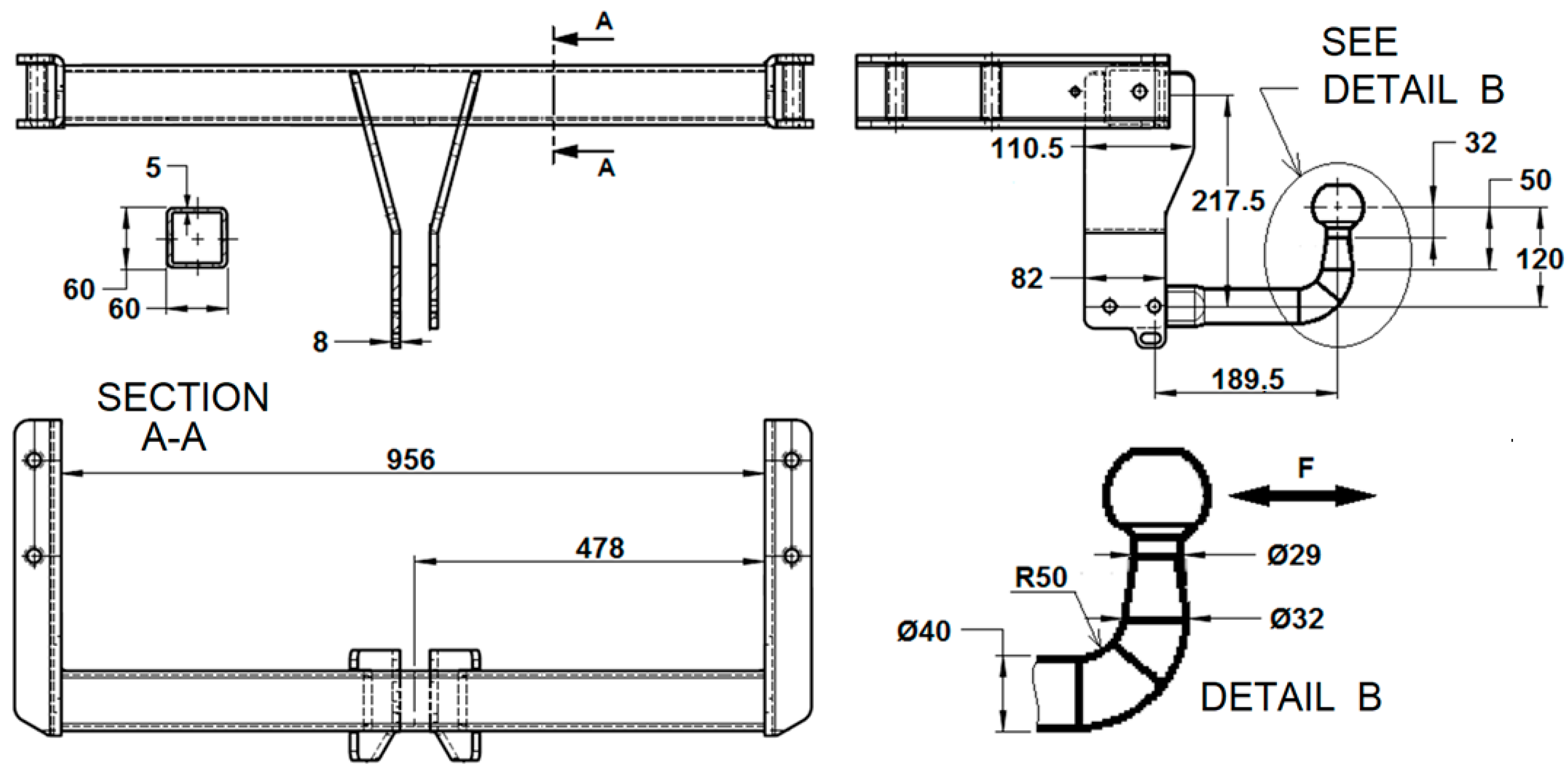
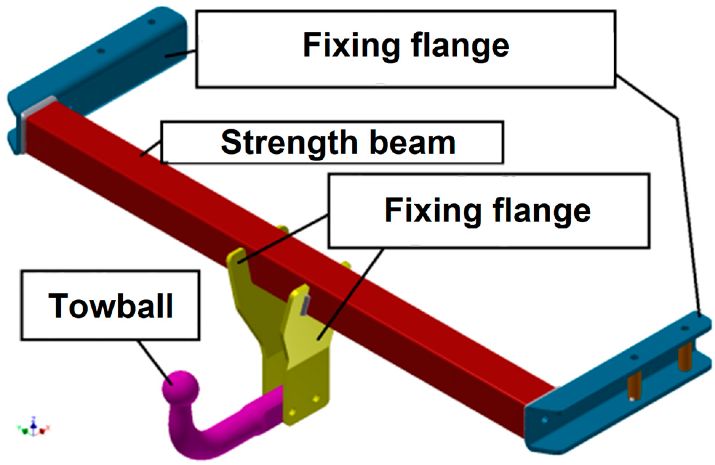
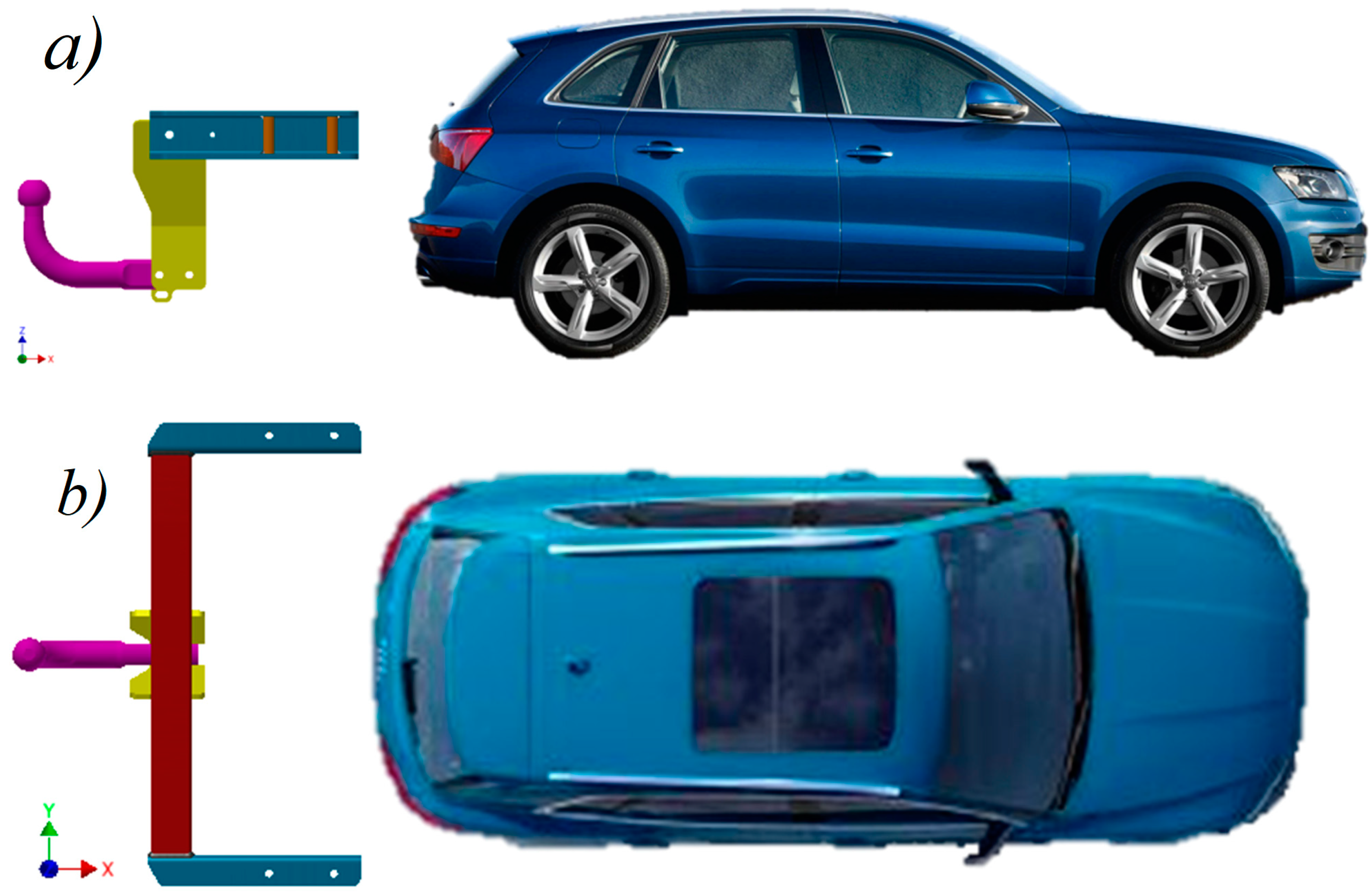
2.1. Presentation of the Studied Towing System
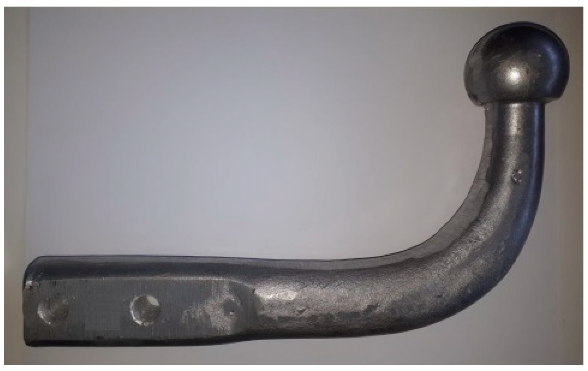
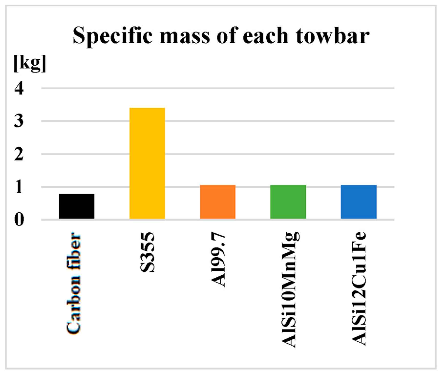
2.2. Materials Used for the Manufacture of the Towball
- Steel hook. It is the solution adopted everywhere at the moment, the steel being easy to obtain, being easy to process and having very good mechanical properties. Some disadvantages will be mentioned next. For steel, the properties considered in the paper are as follows: E = 2.1 · 105 [N/mm2], σe = 355 [N/mm2] and σr = 470 ÷ 630 [N/mm2].
- Aluminum and aluminum alloys. Aluminum alloys with silicon have the advantage of being easily obtained by casting. Also, the mechanical properties of siluminum are very high, which is why they are very common in applications where resistance to mechanical shocks and fatigue is required. The multiple advantages offered by silumins have increased interest in making the towing hook from this material. Additionally, to highlight the major differences in mechanical testing between pure aluminum and aluminum, it was decided to make the towing hook including 99.7% aluminum.
- Steel (S355J2);
- Carbon fibers;
- Al99.7% (pure aluminum);
- AlSi10MnMg;
- AlSi12Cu1Fe.
2.3. Finite Element Method (FEM)
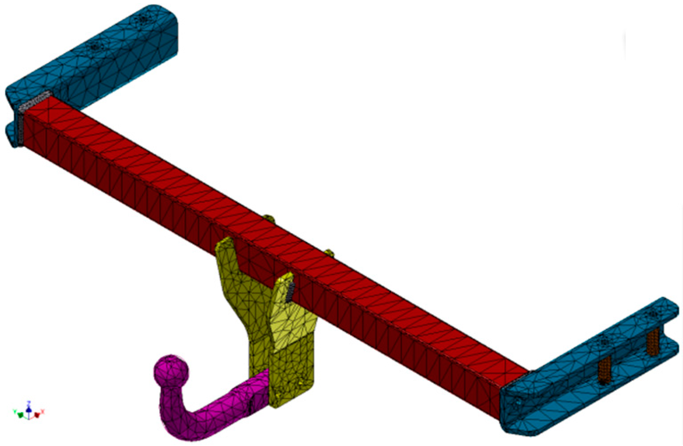
2.3.1. Modeling the Towing System
2.3.2. Model Discretization and Finite Element Analysis
2.3.3. Extracting the Target Results from the Software
2.3.4. Stresses in System
2.3.5. Determination of Displacements
- -
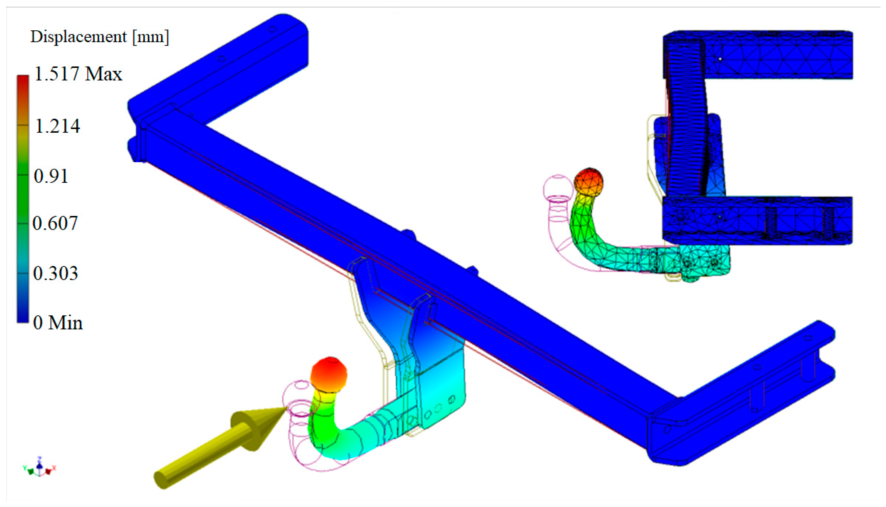
- The maximum displacement occurs at the top left point of the flattening on the hook sphere. The point marked with ‘2’ in Figure 13 represents the place where the most pronounced displacement of the towing system takes place—this point is of less interest in the displacements in the system. The point marked with ‘1’ in the same figure represents the specific point of the center of the sphere, its displacement making the object of interest.
- -
- The sphere moves in two directions. Looking at the studied system from the side of the car (Figure 13), it can be seen that the sphere moves both in the direction X+ (horizontally towards the vehicle) and in the direction Z+ (vertically towards the roof of the car), creating a compound movement. The values of the displacements u1, v1, u2 and v2, but also their vector compounds δu1-v1 and δu2-v2, are specified in Table 2.
- -
- The torsion of the beam tends to cancel out the displacement of the sphere. It can be seen in Figure 13 that the deformation of the hook is achieved by bending in the clockwise direction, and the deformation of the beam is achieved in the opposite direction of rotation (along with the entire towing hook). Therefore, this composition of displacements tends to return the hook sphere to its original position. The return to the initial state of the ball is not achieved because the displacement from the bending of the hook is more pronounced than the reverse displacement given by the torsion of the beam; therefore, the ball tends to move towards the vehicle.
3. Experimental Results
3.1. Detailing the Experimental Process
- -
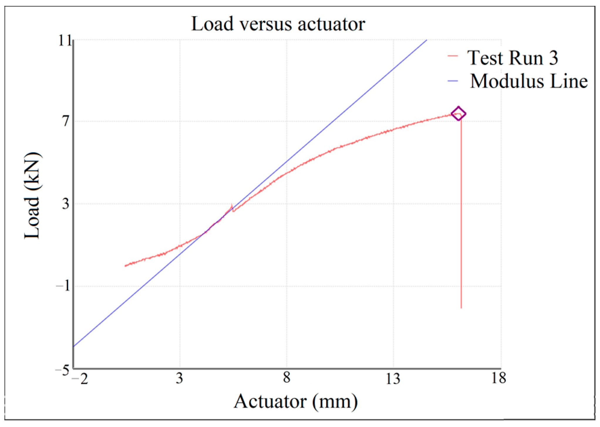
- The experimental determinations consist of testing, on the one hand, the entire towing system and, on the other hand, the towing hooks on a traction machine, simulating vehicle braking with a trailer, an application transposed into compression on the traction machine. The state-of-the-art traction machine has a force capacity of 100 tons and accuracy convenient for experiments (MTS).
- -
- The target of the experimental determinations is that the samples of the tow hooks withstand a force greater than or at least equal to 7500 N, this value resulting from the calculation of heavy braking of a motor vehicle with an attached trailer, where the trailer tends to push the motor vehicle forward.
3.2. Experimental Tests on the Towing System
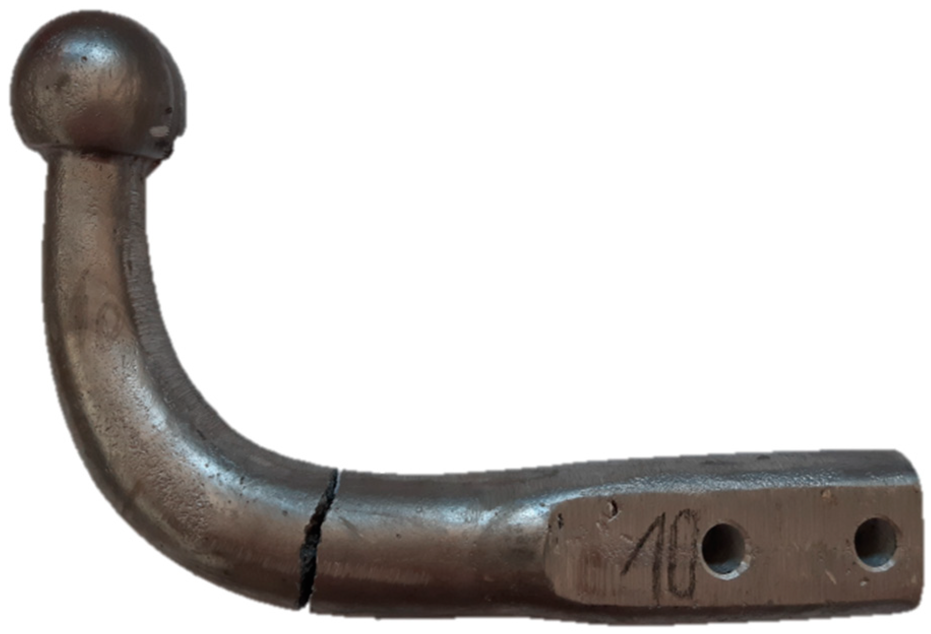
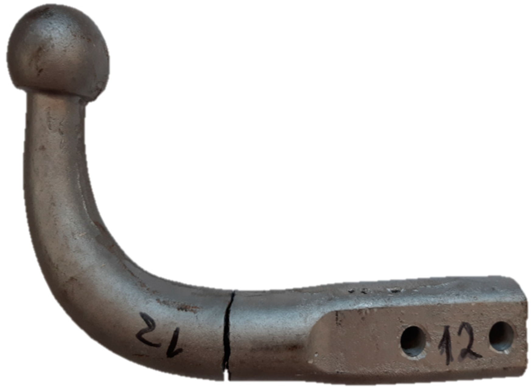
3.3. Experimental Determinations on Towbar

| Material | Maximum Force | Maximum Displacement [mm] | Maximum Stress [MPa] | Specific Mass [Kg/m3] | Rupture YES/NO |
|---|---|---|---|---|---|
| Carbon Fibers | 14,436 | 27.65 | 354.36 | 780 | YES and NO ** |
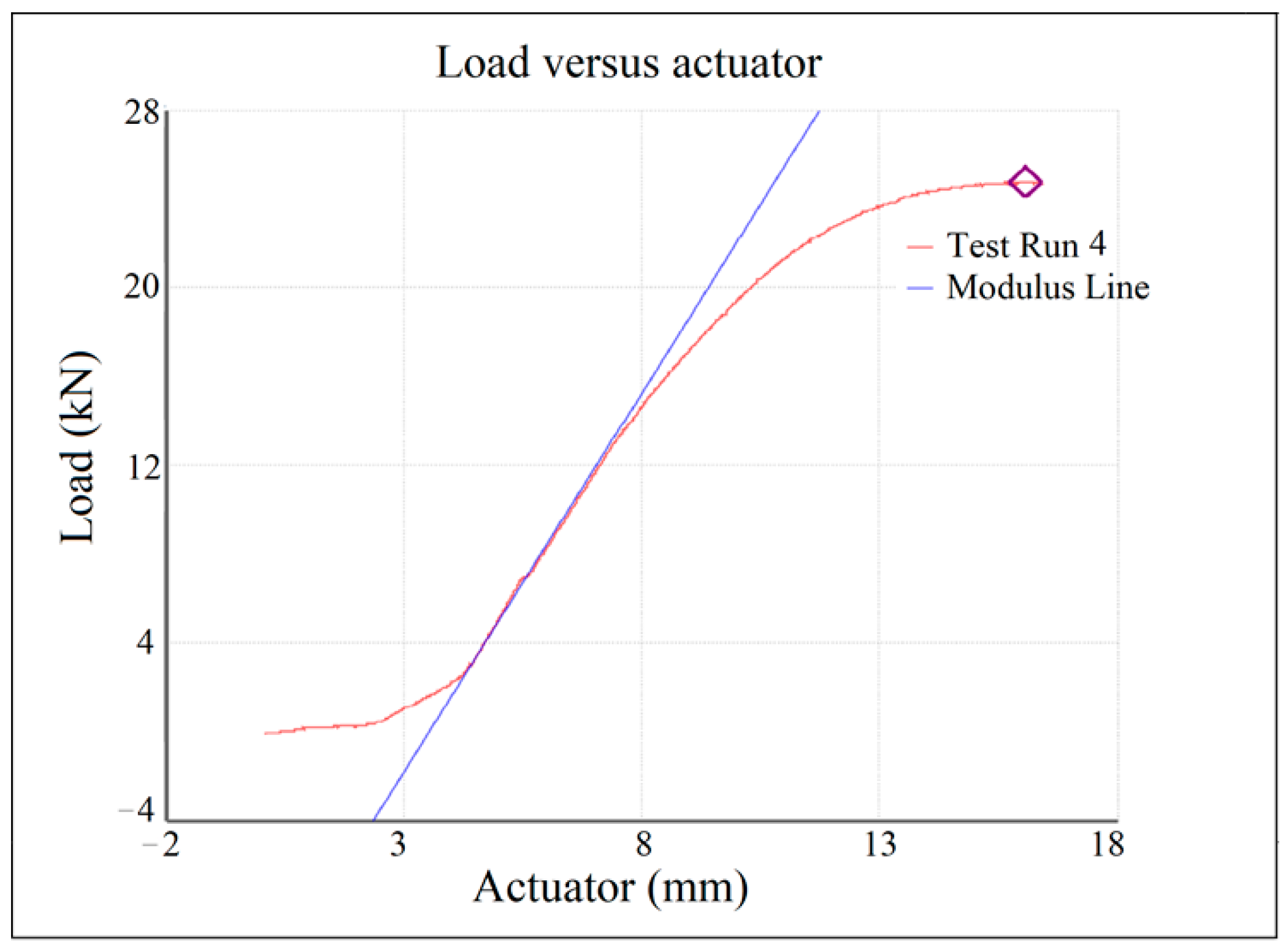
| Steel S355 | 24,724 | 13.85 | 606.89 | 3.400 | NO |
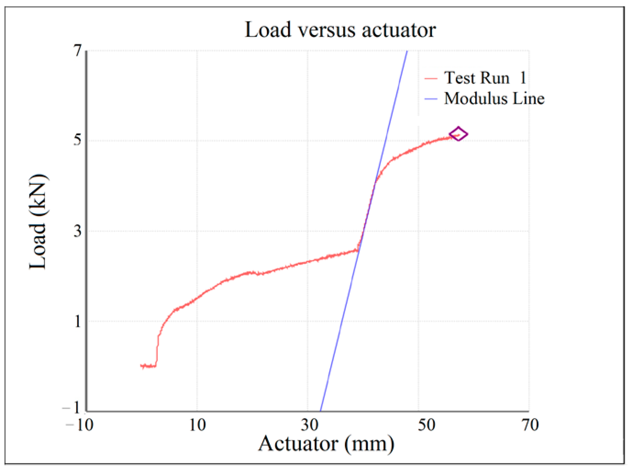
| Aluminum Al99.7 | 5134 *** 2905 | 54.60 | 71.31 | 1.050 | NO |
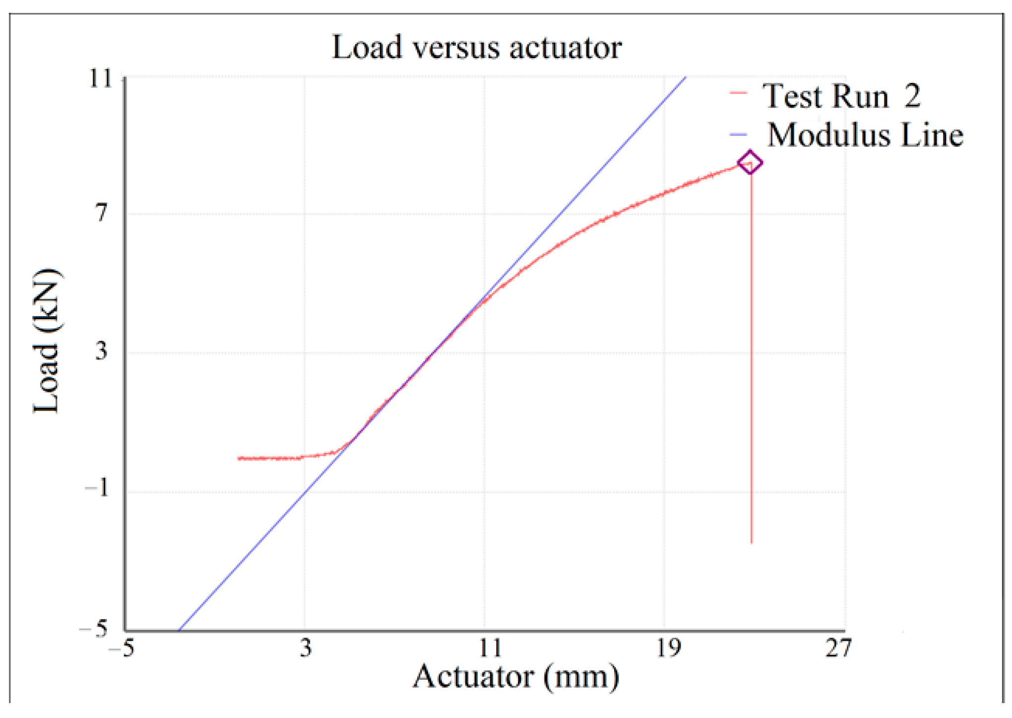
| AlSi10MnMg | 8504 | 18.80 | 208.74 | 1.050 | YES |
| AlSi12Cu1Fe | 7401 | 15.40 | 181.67 | 1.050 | YES |
- ➢
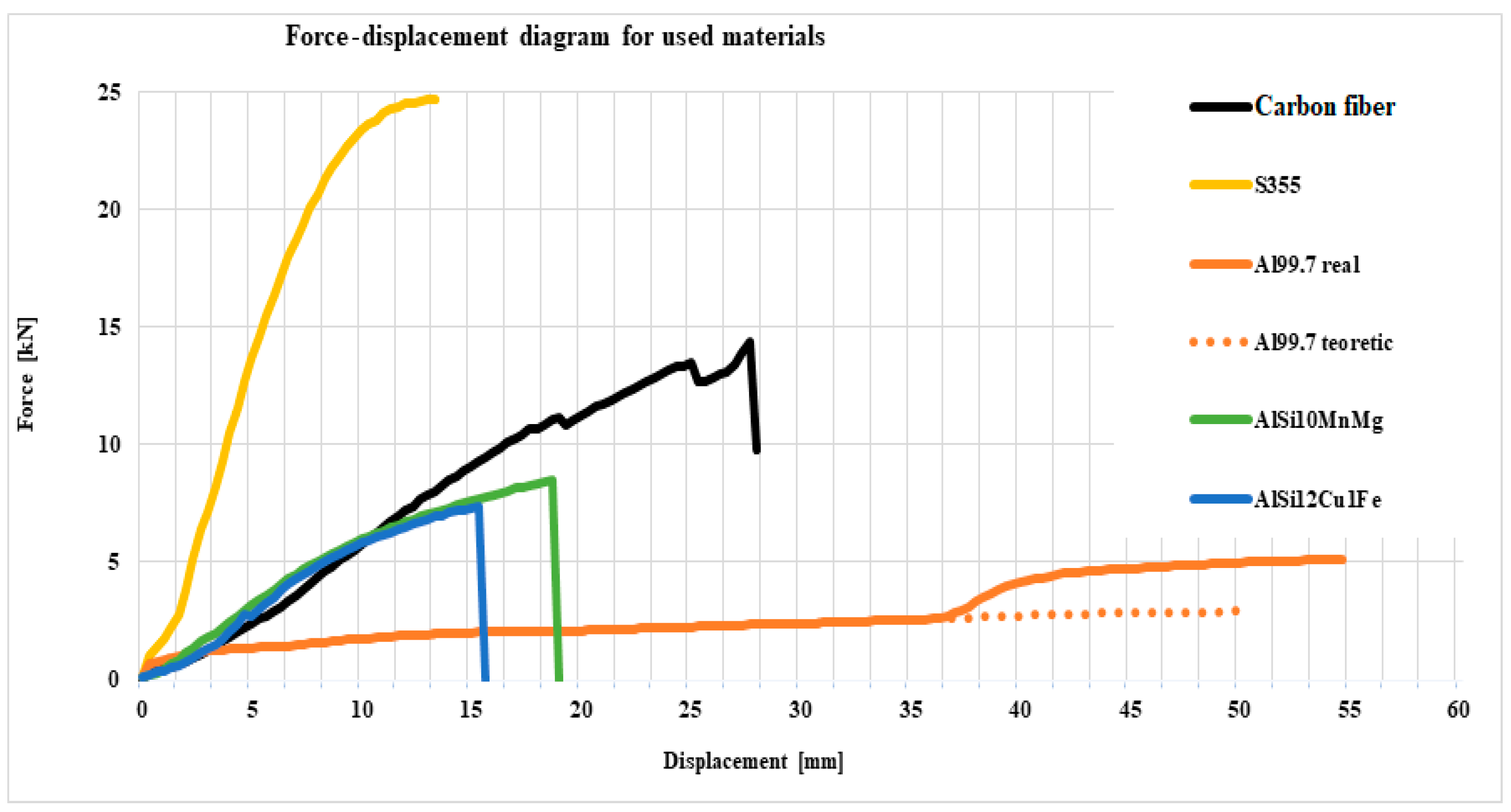
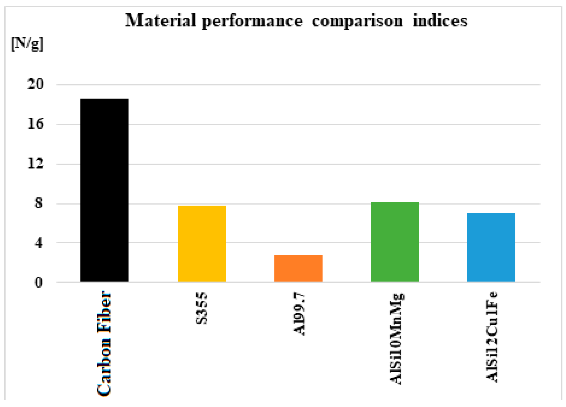
- The carbon fiber towing hook has up to 60% of the strength of the steel one, and the ball displacement is almost double, making it the strongest hook among the hooks made of alternative materials.
- ➢
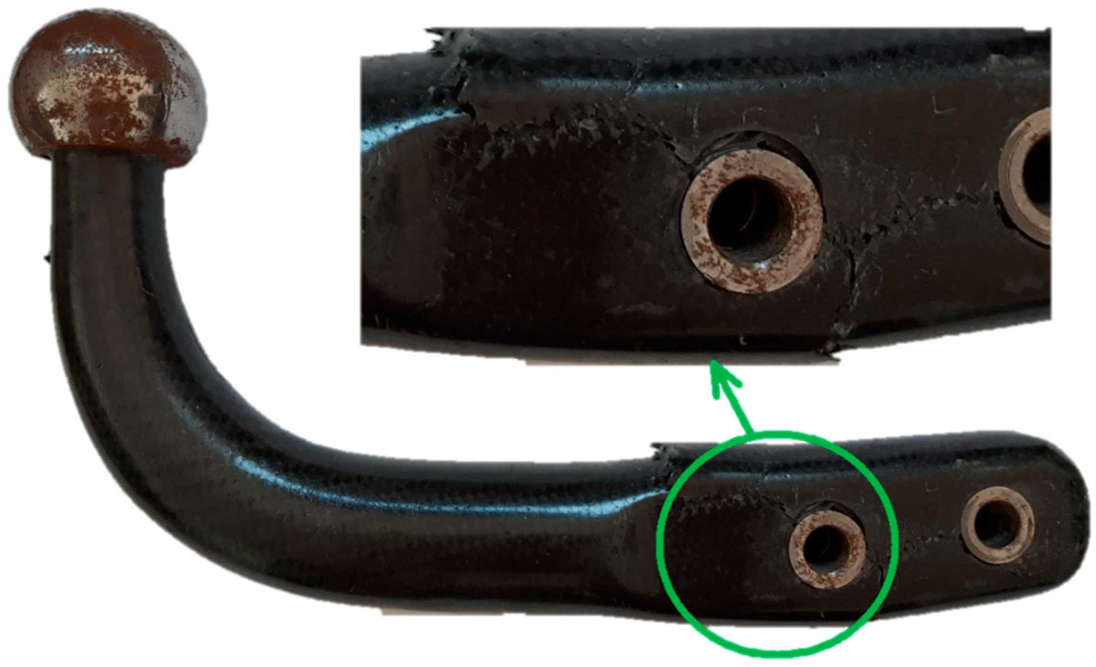
- The same carbon fiber hook shows two sudden decreases in strength, which signifies a state of inhomogeneity, either by the detachment of the metal bushings from the carbon fiber structure, or by the local destruction of some groups of carbon fibers; both possibilities are plausible because, according to the experimental determination, detachment of the two bushings from the fiber structure is observed, as well as ruptures of some groups of fibers.
- ➢
- The AlSi10MnMg towbar has a strength below 35% that of steel, and the displacement is up to 35% higher, this hook having lower performance compared to the one made of carbon fibers, but higher performance compared to AlSi12Cu1Fe.
- ➢
- The AlSi12Cu1Fe hook shows around 30% of the strength of the steel one, the displacement values of the two products being comparable.
- ➢
- The hook made of Al99.7% is the most deficient in terms of mechanical strength, having a resistance of around 12% of that of the steel hook, but it has an excessively high displacement value, being 3.5 times higher.
- ➢
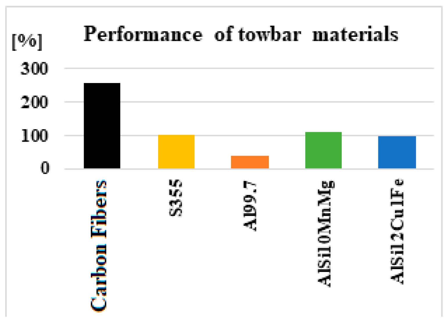
- The towing hook made of composite materials based on carbon fibers would have a mechanical strength superior to that of steel, approximately 2.5 times higher;
- ➢
- Aluminum alloy towbars would have similar mechanical strengths to steel, AlSi10MnMg slightly higher (by around 11%), and AlSi12Cu1Fe slightly lower (by around 3%);
- ➢
- The pure aluminum towbar would have a significantly lower mechanical strength than steel (around 38% of its strength);
- ➢
- A disadvantage of the towing hooks made of the two types of aluminum alloys is the fact that, following the gradual application of force, they reached the stage of being completely destroyed ending up forming two independent bodies.
4. Discussion
- -
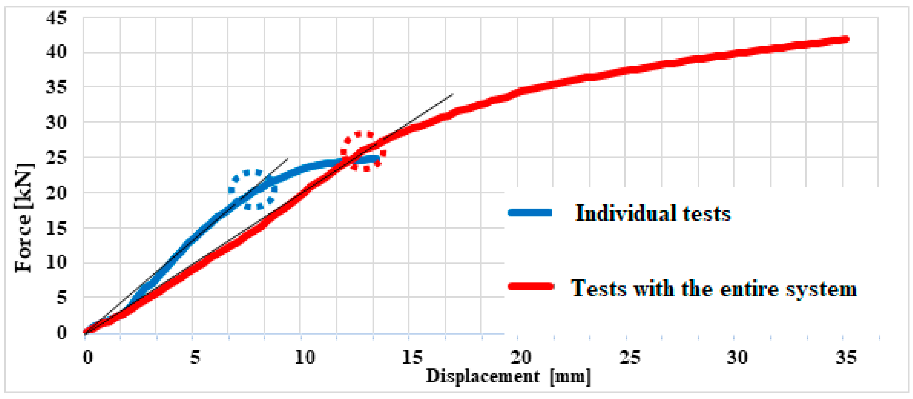
- The individually tested towing hook reaches the plastic domain at an approximate force of FI = 21 kN;
- -
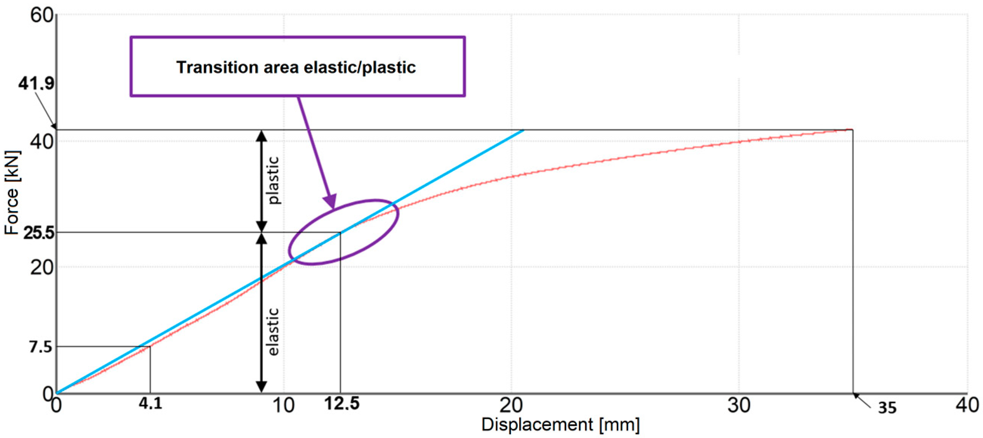
- The tested towbar as a whole reaches the plastic domain at an approximate force of FA = 25.5 kN.
- -
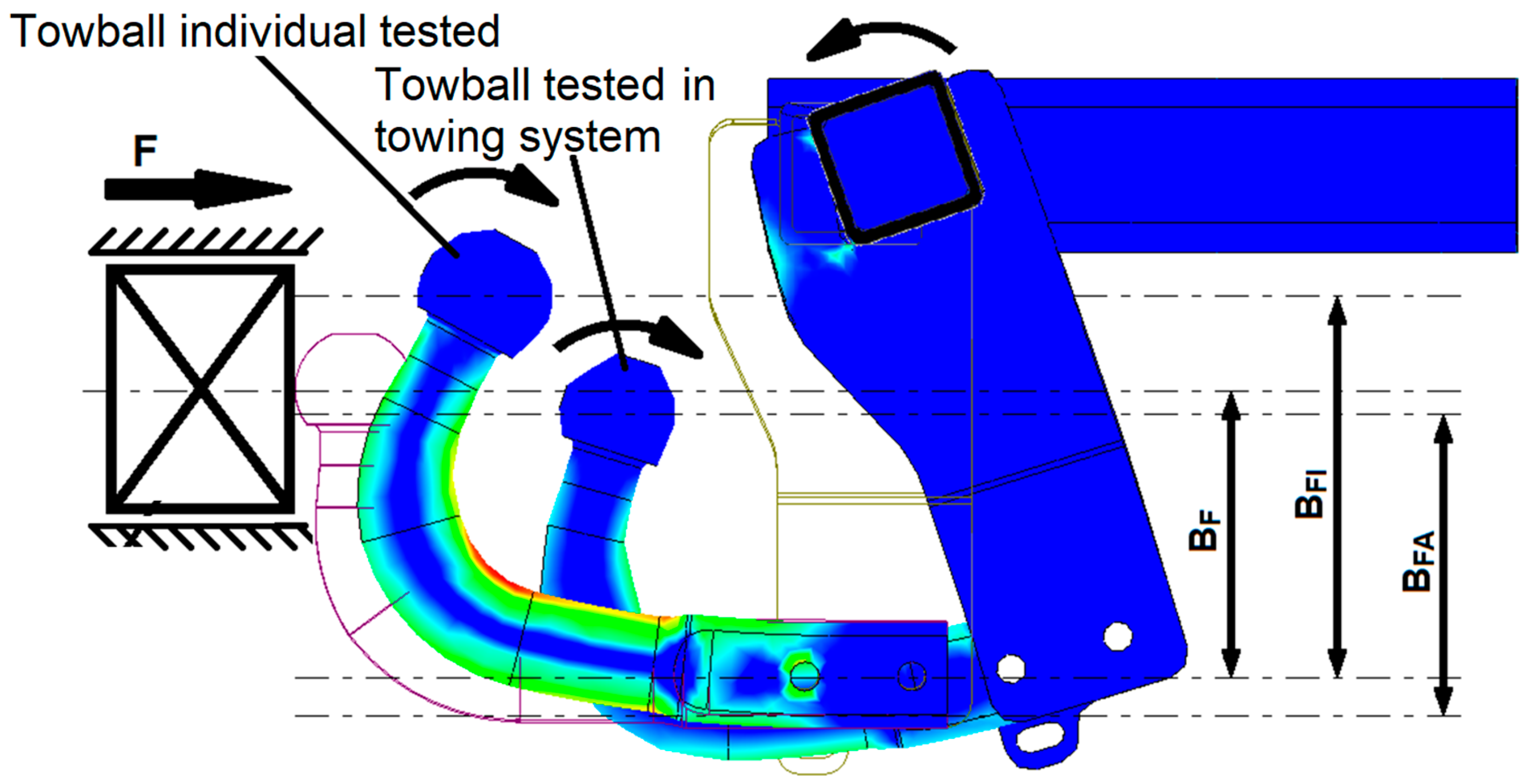
- Up to the force value F = 24.45 kN, the individually tested towing hook has a lower displacement than the one tested in the towing assembly. The deformation of the towing system is based not only on the deformation of the towing hook, but also on the deformations of the resistance beam and on the rotation of the central flanges.
- -
- According to the force value F = 24.45 kN, the towing hook tested individually has a greater displacement than the one tested in the towing assembly. The deformation of the individually tested towbar increases excessively, while the force tends to increase very slowly, the product entering the plastic domain. The ball of the individually tested towbar slides in the direction perpendicular to the direction of the force, increasing the force arm value. The towing assembly continues its linear motion because it has a few more units to travel before reaching the elastic limit.
- -
- Around force F = 25.5 kN, the towing assembly reaches its yield strength, but the test process continues safely with integrity of the assembly. Near the value of F = 42 kN, the experimental testing stopped because the hook was rapidly deformed, the actuation punch being very close to contact with the bending area of the hook, which would have been followed by a considerable but irrelevant increase in force for the present study.
- -
- Since the carbon fiber towing hook suffered cracks in the area of the fixing bolts, it is proposed to optimize the shape of the tail of the hook to obtain an adequate strength.
- -
- The manufacturing process of the carbon fiber towbar is laborious. An optimization involves a design change to help make the manufacturing process easier.
- -
- Aluminum alloys hooks can undergo geometric changes to improve mechanical strength, since the casting process is more convenient than the technological flow of obtaining steel towing hooks.
- -
- Also, the molding process in the forming mixture is very difficult; therefore, a pressure injection mold is proposed, both to optimize the molding process and to obtain a more compact structure of the material of the towing hooks made of aluminum.
- -
- In order to improve the characteristics given by the strength of the aluminum towing hooks, studies are proposed regarding alloying with various other materials that offer higher resistance (e.g., Cu), as well as tests regarding the thermic treatment of the material from which the model is made.
- -
- As a future development of this research, after establishing the processing procedures and choosing the most suitable materials for the construction of the towing hooks, it is proposed to expand the study of the reduction in the mass of the other components in the towing assembly by using alternative materials.
- -
- It is necessary to carry out a study on dynamic fatigue tests of the towing system of alternative materials and on dynamic shock loads, especially if homologation of the system is expected.
5. Conclusions
Author Contributions
Funding
Institutional Review Board Statement
Informed Consent Statement
Data Availability Statement
Conflicts of Interest
References
- Czerwinski, F. Current Trends in Automotive Lightweighting Strategies and Materials. Materials 2021, 14, 6631. [Google Scholar] [CrossRef] [PubMed]
- Chauhan, V.; Kärki, T.; Varis, J. Review of natural fiber-reinforced engineering plastic composites, their applications in the transportation sector and processing techniques. J. Thermoplast. Compos. Mater. 2022, 35, 1169–1209. [Google Scholar] [CrossRef]
- Baker, A.A.; Scott, M.L. Composite Materials for Aircraft Structures, 3rd ed.; American Institute of Aeronautics & Ast.: Reston, VA, USA, 2016. [Google Scholar]
- Barbero, E.J. Introduction to Composite Materials Design; CRC Press: Boca Raton, FL, USA, 2017. [Google Scholar]
- Jarali, O.; Logesh, K.; Hariharasakthisudhan, P. Vibration Based Delamination Detection in Fiber Metal Laminates Composite Beam. Rom. J. Acoust. Vib. 2023, 20, 48–58. [Google Scholar] [CrossRef]
- Usera, D.; Alfieri, V.; Ares, E. Redesign and manufacturing of a metal towing hook via laser additive manufacturing with powder bed. Procedia Manuf. 2017, 13, 825–832. [Google Scholar] [CrossRef]
- Polasik, J.; Walus, K.J.; Mielniczuk, J. Experimental study of the tilt angle body of towing vehicle with different load. In Proceedings of the 21st Polish-Slovak International Scientific Conference on Machine Modeling and Simulations (MMS2016), Hucisko, Poland, 6–8 September 2016; Volume 177, pp. 271–274. [Google Scholar]
- Zatocilová, A.; Koutny, D.; Brandejs, J. Experimental Verification of Deformation Behavior of Towing Hitch by Optical Measurement Method. In Modern Methods of Construction Design: Proceedings of ICMD 2013; Springer: Cham, Switzerland, 2014; pp. 420–430. [Google Scholar]
- Narayanan, S.V.S.; Peters, D. Design and Control of Vehicle Trailer with Onboard Power Supply. SAE Int. J. Passeng. Cars-Electron. Electr. Syst. 2015, 8, 32–40. [Google Scholar] [CrossRef]
- Dehadrai, A.R.; Sharma, I.; Gupta, S.S. Three-Dimensional Dynamics of Towed Underslung Systems Using Geometrically Exact Beam Theory. AIAA J. 2021, 59, 1469–1482. [Google Scholar] [CrossRef]
- Eisenmann, J.; Horsley, J.; Peters, D.L. Small-Scale Physical Modeling and Testing of a Vehicle Trailer with Onboard Power Supply. In Proceedings of the ASME International Design Engineering Technical Conferences and Computers and Information in Engineering Conference (IDETC/CIE), Charlotte, NC, USA, 21–24 August 2016; Volume 2A. [Google Scholar]
- Petracconi, C.L.; Ferreira, S.E.; Palma, E.S. Fatigue life simulation of a rear tow hook assembly of a passenger car. Eng. Fail. Anal. 2010, 17, 455–463. [Google Scholar] [CrossRef]
- Trotea, M.; Constantinescu, A.; Simniceanu, L. Design Optimization of the Towing Hook Used in Passenger Cars for Light Trailers. In Proceedings of the 30th SIAR International Congress of Science and Management of Automotive and Transportation Engineering (SMAT), Jessup, MD, USA, 27 July–7 August 2020; pp. 540–549. [Google Scholar]
- Wang, Z.P. Car Front Towing Hook Analysis and Structural Improvements Based on CAE. In Proceedings of the 2015 International Industrial Informatics and Computer Engineering Conference, Xi’an, China, 10–11 January 2015; pp. 1113–1116. [Google Scholar]
- Balcau, M. Aerodynamic Study of a Car Towing a Motocycle Trailer. Ing. Automob. 2021, 58, 22–26. [Google Scholar]
- Hands, S.J.; Zdravkovich, M.M. Drag Reduction for a Passenger Car Towing a Caravan. J. Wins Eng. Ind. Aerodyn. 1981, 9, 137–143. [Google Scholar] [CrossRef]
- Lufinka, A. Crash test of a tow hitch for car trailers. In Proceedings of the 57th International Scientific Conference on Experimental Stress Analysis (EAN 2019), Luhacovice, Czech Republic, 3–6 June 2019; pp. 264–268. [Google Scholar]
- Teodorescu-Draghicescu, H.; Vlase, S.; Scutaru, M.L.; Serbina, L.; Calin, M.R. Hysteresis effect in a three-phase polymer matrix composite subjected to static cyclic loadings. Optoelectron. Adv. Mater.-Rapid Commun. 2011, 5, 273–277. [Google Scholar]
- Lee, S.W.; Chung, P.W. Finite Element Method for Solids and Structures: A Concise Approach; Cambridge University Press: Cambridge, UK, 2021. [Google Scholar]
- Katouzian, M.; Vlase, S.; Scutaru, M.L. Finite Element Method-Based Simulation Creep Behavior of Viscoelastic Carbon-Fiber Composite. Polymers 2021, 13, 1017. [Google Scholar] [CrossRef] [PubMed]
- Su, R.H.; Wang, B.J.; Peng, C.Y. The finite element analysis on driving wheel-axle system of adhesive tape conveyor with steel wire towing. In Proceedings of the 3rd International Symposium on Modern Mining and Safety Technology, Fuxin, China, 4–6 August 2008; pp. 833–837. [Google Scholar]
- Dizo, J.; Blatnicky, M.; Kafrik, A. Investigation of Driving Stability of a Vehicle-Trailer Combination Depending on the Load’s Position Within the Trailer. Acta Mech. Autom. 2023, 17, 60–67. [Google Scholar]
- Mioch, T.; Kroon, L.; Neerincx, M.A. Driver Readiness Model for Regulating the Transfer from Automation to Human Control. In Proceedings of the 22nd International Conference on Intelligent User Interfaces (IUI-2017), Limassol, Cyprus, 13–16 March 2017; pp. 205–213. [Google Scholar]
- Barbosa, R.M.; Medeiros, E.B. Evaluation of Dynamic Characteristic of Structural Panels with Statistical Energy Analysis. Rom. J. Acoust. Vib. 2023, 20, 139–146. [Google Scholar]
- Li, T.; Zhang, N.; Ma, J.; Yin, G.D. Stability Investigation of Car-trailer Combinations considering Steering System Stiffnesstr. In Proceedings of the 31st Chinese Control and Decision Conference (CCDC), Nanchang, China, 3–5 June 2019; pp. 6040–6045. [Google Scholar]
- Codarcea-Munteanu, L.; Marin, M.; Vlase, S. The study of vibrations in the context of porous micropolar media thermoelasticity and the absence of energy dissipation. J. Comput. Appl. Mech. 2023, 54, 437–454. [Google Scholar]
- Zhang, N.; Yin, G.D.; Chen, N. Analysis of Dynamic Stability of Car-trailer Combinations with Nonlinear Damper Properties. In Proceedings of the IUTAM Symposium on Nonlinear and Delayed Dynamics of Mechatronic Systems, Nanjing, China, 17–21 October 2017; Volume 22, pp. 251–258. [Google Scholar]
- Vörós, I.; Takács, D. The Effectes of Trailer Towing on the Dynamics of a Lane-Keeping Controller. In Proceedings of the Annual ASME Dynamic Systems and Control Conference (DSCC2020), Pittsburgh, PA, USA, 5–7 October 2020; Volume 1. [Google Scholar]
- Khalkar, V.; Hariharasakthisudhan, P.; Kalamkar, R. Some Studies Verify the Applicability of the Free Vibration Method of Crack Detection in Composite Beams for Different Crack Geometries. Rom. J. Acoust. Vib. 2023, 20, 30–41. [Google Scholar]
- Borsutkar, S.; Gujar, A.; Dongarkar, Z.; Chavan, V.; Horambe, P. Design and Fabrication of Car Towing Attachment. Int. J. Adv. Res. Sci. Commun. Technol. 2024, 4, 309–312. [Google Scholar] [CrossRef]
- Abouelregal, A.E.; Marin, M.; Öchsner, A. The influence of a non-local Moore–Gibson–Thompson heat transfer model on an underlying thermoelastic material under the model of memory-dependent derivatives. Contin. Mech. Thermodyn. 2023, 35, 545–562. [Google Scholar] [CrossRef]
- Marin, M.; Öchsner, A.; Vlase, S.; Grigorescu, D.O.; Tuns, I. Some results on eigenvalue problems in the theory of piezoelectric porous dipolar bodies. Contin. Mech. Thermodyn. 2023, 35, 1969–1979. [Google Scholar] [CrossRef]
- Saputro, R.K.; Afisa, T.; Hendratno, D.S.P.; Reginawati, T.; Hilal, A.; Ambarwati, D. Innov. Bus. Manag. Account. J. 2023, 2, 67–76. [CrossRef]
- Caruso, M.; Gorella, N.S.; Gallina, P.; Seriani, S. Towing an Object with a Rover. J. Mech. Robot. 2024, 17, 021001. [Google Scholar] [CrossRef]
- Zhao, L.J.; Yang, J.G.; Jiang, J.H. Testing the Hybrid Hydraulic Drive Aircraft Tractor Via LXI Bus Technique. In Proceedings of the 2009 International Workshop Information Security and Application, Busan, Republic of Korea, 25–27 August 2009; pp. 47–50. [Google Scholar]
- Wang, N.J.; Liu, H.B.; Yang, W.H. Simulation Study of the Backward-Motion for a Aircraft Towbar less Tractor. In Proceedings of the 12th IEEE International Conference on Computer-Aided Industrial Design and Conceptual Design, Chongqing, China, 1–8 January 2011; Volume 1–2, pp. 762–766. [Google Scholar]
- Vlase, S.; Marin, M.; Bratu, P.; Bratu, P.; Manea, R.; Shrrat, O.A.O. Analysis of Vibration Suppression in Multi-Degrees of Freedom Systems. Rom. J. Accoustic Vib. 2022, 19, 149–156. [Google Scholar]
- Olesen, A.V.; Elvik, R.; Lahrmann, H.S. Does a tow-bar increase the risk of neck injury in rear-end collisions? J. Saf. Res. 2018, 65, 59–65. [Google Scholar] [CrossRef] [PubMed]
- Beregi, S.; Takács, D.; Barton, D.A.W. Stability analysis of the car-trailer system with a time-delayed tyre model. In Proceedings of the 24th Symposium of the International-Association-for-Vehicle-System-Dynamics (IAVSD), Dynamics of Vehicles on Roads and Tracks, Graz, Austria, 17–21 August 2015; pp. 643–652. [Google Scholar]
- Park, M.; Chung, W.; Kim, M. Experimental research of a passive multiple trailer system for backward motion control. In Proceedings of the 2005-IEEE International Conference on Robotics and Automation (ICRA), Barcelona, Spain, 18–22 April 2015; Volumes 1–4, pp. 105–110. [Google Scholar]
- Rükgaur, A.; Petersen, U.; Schiehlen, W. Lateral dynamics of towed vehicles. In Proceedings of the 2nd International Conference on Road Vehicle Automation (ROVA 95), Bolton, UK, 11–13 September 1995; Road Vehicle Automation II. pp. 90–99. [Google Scholar]
- Szaksz, B.; Stepan, G. Delay Effects in the Dynamics of Human Controlled Towing of Vehicles. J. Comput. Nonlinear Dyn. 2023, 18, 061003. [Google Scholar] [CrossRef]
- Modrea, A.; Vlase, S.; Horatiu, T.-D.; Mihalcica, M.; Calin, R.; Astalos, C. Properties of advanced new materials used in automotive engineering. Optoelectron. Adv. Mater.-Rapid Commun. 2013, 7, 452–455. [Google Scholar]
- Semionovas, E.; Juodvalkis, D.; Skvireckas, R. The Stand Simulation of Stability of a Car with a Trailer. In Proceedings of the 22nd International Scientific Conference on Transport Means, Trakai, Lithuania, 3–5 October 2018; Volume PTS I-III, pp. 1265–1267. [Google Scholar]
- Marin, M.; Chirila, A.; Oechsner, A.; Vlase, S. About finite energy solutions in thermoelasticity of micropolar bodies with voids. Bound. Value Probl. 2019, 2019, 89. [Google Scholar] [CrossRef]
- Xavier, J.R.; Vinodhini, S.P.; Beryl, J.R. Innovative multifunctional nanocomposite coated aluminum alloy for improved mechanical, flame retardant, and corrosion resistance in automobile industries. J. Adhes. 2024; early access. [Google Scholar]
- Mokhtari, M.A.; Nikzad, M.H. Multi-objective optimization and comparison of machine learning algorithms for the prediction of tensile properties of aluminum-magnesium alloy. Mater. Today Commun. 2024, 40, 109476. [Google Scholar] [CrossRef]
- Sun, Y.T.; Akçay, F.A.; Bai, Y.L. Analytical and numerical modeling on strengths of aluminum and magnesium micro-lattice structures fabricated via additive manufacturing. Prog. Addit. Manuf. 2024; early access. [Google Scholar]
- Gu, D.D.; Meiners, W.; Wissenbach, K.; Poprawe, R. Laser additive manufacturing of metallic components: Materials, processes and mechanisms. Int. Mater. Rev. 2012, 57, 133–164. [Google Scholar] [CrossRef]
- Cui, J.R.; Roven, H.J. Recycling of automotive aluminum. Trans. Nonferrous Met. Soc. China 2010, 20, 2057–2063. [Google Scholar] [CrossRef]


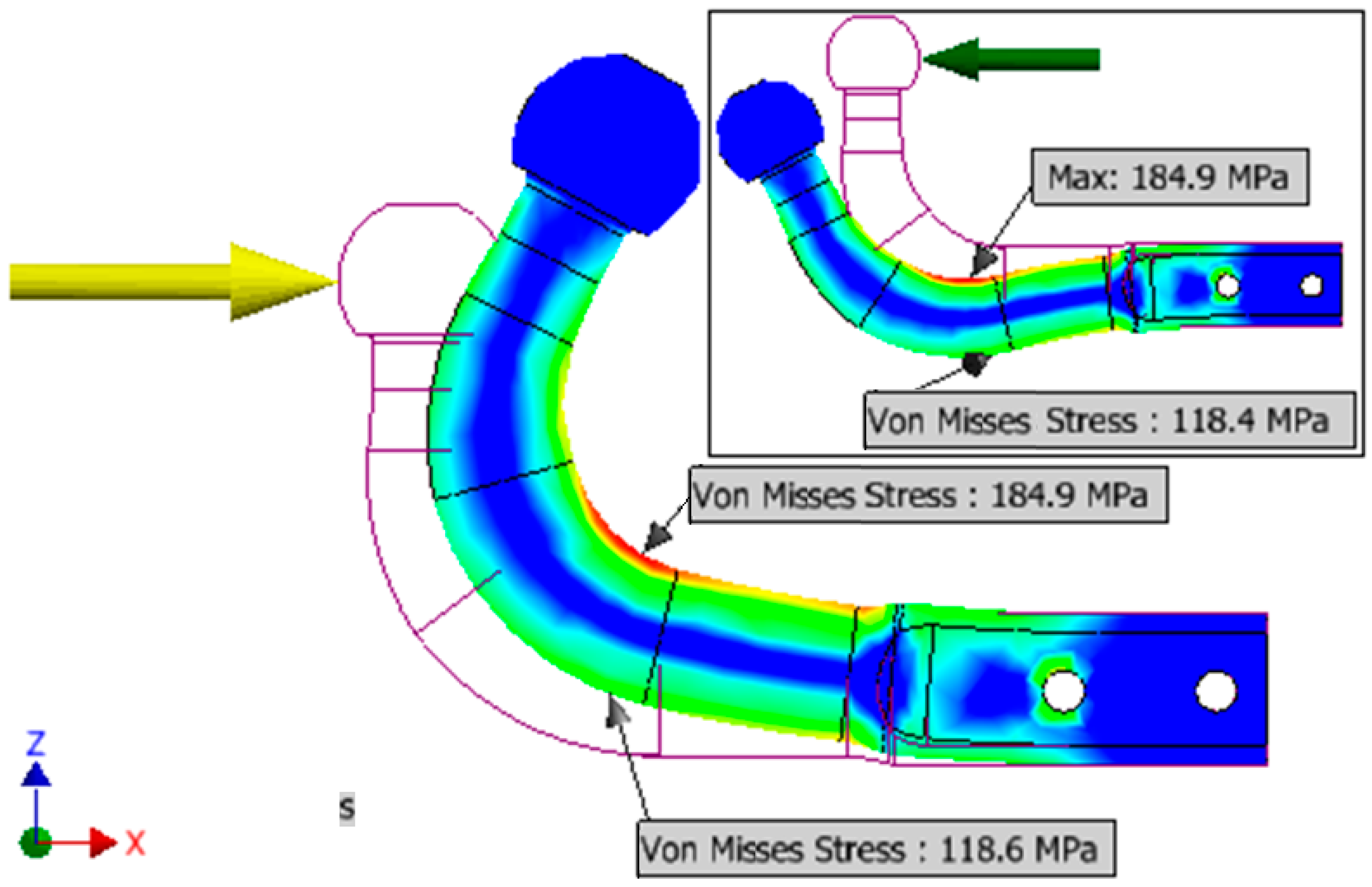


| The Requested Component | The Area of the Resulting Stress | Stress [MPa] |
|---|---|---|
| The inside of the radius of curvature | The inside of the radius of curvature, σint | 184.9 |
| The outside of the radius of curvature, σext | 118.6 | |
| Resistance beam | Extremity | 63.4 |
| Displacement | Symbol | Value [mm] |
|---|---|---|
| The horizontal displacement of the center of the sphere | u1 | 1.313 |
| Vertical displacement of the center of the sphere | v1 | 0.295 |
| Compound displacement of the center of the sphere | δu1-v1 | 1.346 |
| Maximum horizontal displacement of the sphere | umax = u2 | 1.474 |
| Maximum vertical displacement of the sphere | vmax = v1 | 0.357 |
| Maximum compound displacement of the sphere | δmax = δu1-v1 | 1.517 |
| Displacement | Symbol | Value [mm] |
|---|---|---|
| Horizontal displacement of the center of the sphere | u1′ | 0.826 |
| Vertical displacement of the center of the sphere | v1′ | 0.589 |
| Compound displacement of the center of the sphere | δu1′-v1′ | 1.015 |
| Characteristic | Force [kN] | Stress [MPa] | Displacement [mm] |
|---|---|---|---|
| Analytical calculation area, necessary for the study | 7.5 | 184.9 | 4.1 |
| The limit of elasticity | 25.5 | 628.7 | 12.5 |
| The maximum acting force on the system | 41.9 | 1.033 | 35 |
| Method | Determination Area | ||
|---|---|---|---|
| The Inside of the Radius of Curvature of the Towing Hook, σint | The Outside of the Radius of Curvature of the Towing Hook, σext | The Ends of the Resistance Beam of the Entire Towing System | |
| [MPa] | [MPa] | [MPa] | |
| Classical model | 188 | 117.04 | 63.82 |
| FEM | 184.9 | 118.6 | 63.4 |
Disclaimer/Publisher’s Note: The statements, opinions and data contained in all publications are solely those of the individual author(s) and contributor(s) and not of MDPI and/or the editor(s). MDPI and/or the editor(s) disclaim responsibility for any injury to people or property resulting from any ideas, methods, instructions or products referred to in the content. |
© 2024 by the authors. Licensee MDPI, Basel, Switzerland. This article is an open access article distributed under the terms and conditions of the Creative Commons Attribution (CC BY) license (https://creativecommons.org/licenses/by/4.0/).
Share and Cite
Petrici, A.V.; Scutaru, M.L.; Gheorghe, V.; Vlase, S. Alternative Solution for Towing Systems Used in the Automotive Industry. Appl. Sci. 2024, 14, 9131. https://doi.org/10.3390/app14199131
Petrici AV, Scutaru ML, Gheorghe V, Vlase S. Alternative Solution for Towing Systems Used in the Automotive Industry. Applied Sciences. 2024; 14(19):9131. https://doi.org/10.3390/app14199131
Chicago/Turabian StylePetrici, Andrei Victor, Maria Luminita Scutaru, Vasile Gheorghe, and Sorin Vlase. 2024. "Alternative Solution for Towing Systems Used in the Automotive Industry" Applied Sciences 14, no. 19: 9131. https://doi.org/10.3390/app14199131