Article

Experimental and Numerical Research on the Splitting Capacity of European Beech Beams Loaded Perpendicular to the Grain by Connections: Influence of Different Geometrical Parameters

by
José Luis Gómez-Royuela
1,
Almudena Majano-Majano
1,
Antonio José Lara-Bocanegra
1,
José Xavier
2,3,* and
Marcelo F. S. F. de Moura
4
1
Department of Building Structures and Physics, ETS of Architecture, Universidad Politécnica de Madrid (UPM), Avda. Juan de Herrera 4, 28040 Madrid, Spain
2
UNIDEMI, Department of Mechanical and Industrial Engineering, NOVA School of Science and Technology, Universidade NOVA de Lisboa, 2829-516 Caparica, Portugal
3
Laboratório Associado de Sistemas Inteligentes, LASI, 4800-058 Guimarães, Portugal
4
Department of Mechanical Engineering and Industrial Management, Faculty of Engineering, University of Porto, Rua Dr. Roberto Frias, 4200-465 Porto, Portugal
*
Author to whom correspondence should be addressed.
Appl. Sci. 2024, 14(2), 900; https://doi.org/10.3390/app14020900
Submission received: 19 December 2023 / Revised: 17 January 2024 / Accepted: 18 January 2024 / Published: 20 January 2024
(This article belongs to the Special Issue Advances in Engineered Wood Products and Timber Structures)

Abstract

:
In the present work, single- and double-dowel joints following different geometric configurations are experimentally and numerically investigated to derive the splitting behaviour of beech wood (Fagus sylvatica L.), one of the most widespread hardwood species in Europe for structural purposes. The influence of the spacing between dowels, their distance to the supports, and the slenderness of the beams is analysed. The correlation of the experimental failure loads with those predicted numerically by cohesive zone finite element-based models using the fracture properties of the species is discussed. The experimental results are also compared with those obtained from the normative expression included in Eurocode 5 and two other design models reported in the literature. The splitting failure loads predicted by both the analytical and numerical models were found to be conservative, the latter being closer to the experimental values.

1. Introduction

In recent decades, there has been significant growth in the development of renewable and environmentally sustainable building materials, spurred by the imperative to address the impacts of climate change. The building sector is a significant consumer of primary energy, contributing significantly to the release of substantial amounts of carbon dioxide (CO2) into the atmosphere [1,2]. In this context, wood and wood-based products have attracted great interest in architecture and civil engineering because of their renewable resource potential when sustainably managed [3], their savings in primary energy and CO2 emissions during the manufacturing process [1,4], and the added value they bring to buildings. Furthermore, among the main structural building materials, wood is the only one composed of substantial amounts of carbon captured from the atmosphere during the tree growth process (around 50% of its dry weight) [5]. Currently, most structural timber products are made from softwoods, but in recent years, there has been growing interest in the use of hardwoods for structural purposes. The reasons for this are multiple and may be due, among others, to the under-use of aged hardwood forests and the high mechanical properties compared to softwoods [6,7].
In this respect, Fagus sylvatica L., or European beech, is one of the most important and widespread hardwood species in Europe (from southern Scandinavia to northern Sicily and from northwestern Turkey to northwestern Spain), with an average height of about 30–40 m. [8,9]. The large beech reserves available in European forests have aroused the interest of the scientific community. Several investigations have been carried out on this material for structural purposes, both on solid wood in terms of determining its elastic constants [10,11,12,13], mechanical properties [14,15,16], or fracture behaviour [17,18], as well as on structural products made of beech such as glulam [19] or laminated veneer lumber (LVL) [20]. European beech also offers good strength and stiffness compared to softwoods, which makes it an excellent choice for the design of timber structures, especially in the assessment of high-performance scenarios, such as connections with fasteners or large span elements, allowing for a reduction in the cross-section of the main members.
Mechanical connections with steel dowel-type fasteners are among the most widely used connections in timber structures [21,22,23] because of their simplicity of manufacture and assembly and the possibility of being designed to have a ductile connection failure. However, there are certain situations where brittle failure of the timber member may occur at load levels below the bearing capacity for desirable ductile behaviour, especially in designs with connections loaded at an angle to grain where tension stresses perpendicular to the grain are induced, for which timber inherently exhibits relatively low strength and stiffness. This brittle splitting failure is, therefore, one of the most critical in timber structures and deserves particular concern in design.
Eurocode 5 [24] includes the so-called European Yielding Model (EYM) originally formulated by Johansen [25], which is used to predict the load carrying capacity of dowel-type connections subjected to shear force. This model always considers the plastic behaviour of timber and also the possible plastic behaviour of the dowel depending on the failure mode of the connection. However, this model can dangerously overestimate the ultimate load in connections if splitting failure occurs. Concerning the prediction of the splitting capacity of connections loaded at an angle to the grain, Eurocode 5 provides a relatively simple relationship developed theoretically by Van der Put and Leijten [26,27] following an energetic approach in the framework of linear elastic fracture mechanics (LEFM). The expression only applied to softwood and considered the timber member width, the distance from the fastener to the loaded edge of the member, and the ratio of the latter to the member depth (commonly known as the α parameter). It is widely demonstrated and specified in some design codes that when α ≥ 0.7, splitting may be neglected. The expression also includes a constant value arising from the fracture energy calibration parameter. However, the scientific literature suggests that this value is a considerable overestimation for some wood species commonly used in Europe [28]. The expression disregards the influence of other parameters, such as the number and geometry of groups of fasteners.
Further experimental and numerical research has been carried out to propose alternative analytical formulations to the normative expression, taking into account the effect of different geometrical parameters of the connection and material properties. Most of these experimental studies have been conducted on softwoods, e.g., the first studies reported in [29,30,31,32] used to calibrate the analytical model proposed by Van der Put and Leijten or later relevant studies on sawn spruce and glulam [33,34,35,36], radiata pine LVL [37], southern pine LVL [38,39], and southern pine MSR lumber [38]. However, very little research has focused on the splitting behaviour of dowel connections in hardwood species. Recent studies can be found on Eucalyptus globulus sawn wood [40] and yellow poplar PSL [38]. There is a work on beech beams loaded perpendicularly to the grain by connections, although the α values considered were higher than 0.7 [23].
In terms of numerical investigations, several authors have developed finite element models (FEMs) to realistically replicate the behaviour of structural timber elements with fastener connections [22,34,41,42,43]. One method involves utilising cohesive zone models (CZMs) incorporating traction–separation laws, which are treated as inherent material properties. These models require predefining possible damage paths. Strength criteria based on limit stresses are applied to indicate the onset of the damage. Damage evolves as described by the traction–separation law following the principles of fracture mechanics. This method was first applied to wood in [44], and its capability has been sufficiently demonstrated in subsequent studies [41,42,45], as well as in previous work by the authors focusing on the simulation of crack propagation in double cantilever beams (DCBs) [17] and end-notched flexure (ENF) tests [18] in beech wood, offering good agreement with experimental results.
The main objective of the present research is to determine the splitting capacity of Fagus Sylvatica L. (European beech) solid wood beams loaded perpendicular to the grain by connections, considering α values lower than 0.7. An experimental campaign is carried out on connections consisting of one and two dowels placed at various positions along beams of different lengths and depths aiming to study the influence of these geometrical parameters. Cohesive zone finite element-based models using the fracture properties of the species are also developed, which are capable of reproducing crack development. Finally, the results are compared with the theoretical splitting failure loads obtained by applying the analytical expression included in Eurocode 5 [24] and two other alternative design models reported in the literature [46,47], which offer a more complete formulation regarding the consideration of different geometrical parameters of the connection.

2. Materials and Methods

2.1. Experimental Test

European beech (Fagus sylvatica L.) solid wood from Austria was used in the experimental tests. The boards were obtained from heartwood and cut in the tangential direction. Before testing, the boards were conditioned in a climatic chamber at 20 °C and 65% relative humidity until equilibrium moisture content (MC) was reached. After conditioning, all boards were visually graded according to the German standard DIN 4074-5:2008 [48]. The specimens were free from knots and cracks. All specimens met the requirements for the LS13 strength class [48], which would allow a strength class assignment of D40 according to EN 1912:2012 [49]. MC was determined using the oven-drying method using a section taken from each board following EN 13183-1:2002 [50]. This resulted in an average value of 10.3%. The density (ρ) was also measured using a section taken from each board according to EN 408:2012 [51] and adjusted to the reference moisture content of 12% [52], giving a mean value of 732 kg/m3.
The beams were subjected to 3- or 4-point bending tests depending on the connection layout studied (Figure 1), at a constant crosshead displacement rate set between 0.75 and 3.50 mm/min, so that failure took place in approximately 5 min.
Displacements (δ) were measured using linear variable differential transformers (LVDTs) and recorded at a frequency of 1 Hz during the tests. To analyse joint behaviour and dowel sliding, LVDTs were placed both at the bottom of the loading plates, as close as possible to the dowel, and at the bottom of the beam (black triangles in Figure 1). Holes of the same diameter as the dowels were drilled in the timber beams so that there was no clearance between them.
The experimental programme was divided into two groups of specimens according to the beam depth (h): group 1 with h = 100 mm and group 2 with h = 200 mm. The beam width (b) was 48 mm for all specimens. In all tests, dowels with a diameter (d) of 16 mm and 120 mm length made of S355-grade steel were used. With this diameter, the dowel slenderness (b/d) was small, and steel yielding was avoided.
The distance to the loaded edge (he) was set at 4d (minimum distance established in Eurocode 5 [24]), remaining constant in all tests, resulting in joints with two different values of the α parameter (α = he/h), namely 0.64 for group 1 and 0.32 for group 2. In each of the groups, beams with one dowel (1D) and two dowels (2D) were tested in order to analyse the influence of the number of dowels and connections on the splitting capacity.
As a reference configuration, a span L of 950 mm (1000 mm specimen length) and one connection with 1D and 2D (spaced ar = 4d apart) located at mid-span were established. In order to analyse the influence of the distance lb from the connection to the support and the distance lc between the connections on the splitting capacity, different lb values were considered (360 mm, 240 mm, and 120 mm), which corresponded to support spacings of approximately 0.38, 0.25, and 0.13 times the span. In order to also analyse the influence of the slenderness of the beam on the splitting capacity, beams with the connection at mid-span but with L of 450 mm (500 mm specimen length) were also tested. Figure 2 illustrates the set of reference configurations and their variations.
Table 1 summarises, for each series of tests, the geometrical parameters of the beam (span and depth), as well as the density and moisture content, the position of the connection in terms of distance to the support lb and the spacing between connections lc (in case of two connections), the position of the connection in relation to the beam depth by means of the α parameter, and the number of replicates tested.

2.2. Numerical Analysis

Numerical finite element analyses of all configurations studied in the experimental campaign (Figure 2) were carried out using ABAQUS v2021 software [53]. Brittle splitting failure is addressed as simply as possible and in a way that provides sufficiently safe results from a structural design point of view.
Since the dowel had low slenderness, it showed very small deformations, and the authors did not observe any yield hinges, so a simplified 2D model was developed in which a cohesive zone model (CZM) was implemented to reproduce the crack growth. The timber beam and the steel elements (supports and dowels) were defined by 8-node quadratic plane stress elements (CPS8R). The model mesh was refined in the crack propagation region, as well as in the dowel and support locations (Figure 3a,b), using a minimum and maximum mesh size of 1 mm × 1 mm and 4 mm × 4 mm, respectively. To simulate crack growth and propagation, 6-node quadratic cohesive surfaces were used together with the Newton–Cotes integration scheme [54]. To reduce the computational time and in accordance with the findings in [55], only one fracture plane at mid-height of the dowel was modelled. The contact between the steel elements and wood was introduced using 6-node quadratic contact surfaces with a friction coefficient of 0.15 [56]. The analyses were carried out considering a non-linear geometrical behaviour of the beams. The Newton–Raphson convergence method was applied to solve the systems of non-linear equilibrium equations. An isotropic material was considered for steel elements and an orthotropic material for wood. The yielding behaviour of wood was neglected for the sake of the simplification intended by the model. Consequently, a linear elastic constitutive response of the materials was assumed. The application of the load was performed by a uniform vertical displacement imposed at the central node of the dowels in the range of 6 and 20 mm introduced in increments of no more than 0.01 mm to reproduce stable crack growth and to obtain accurate results.
A bilinear cohesive law model with a linear softening relationship was used to reproduce the fracture process in mixed-mode I + II (Figure 4) [57,58].
The proposed damage model is characterised by two branches. The first one describes the elastic behaviour of the undamaged material until the stress limit (fu,i, i = I, II, m) is reached, and the second one defines the softening behaviour under damage (Figure 4). Under mixed−mode I + II, an equivalent relative displacement combining the two loading modes is defined (Figure 4) according to Equation (1):
δ m = δ I 2 + δ II 2
which can be written as
δ m = δ I 1 + β 2
being
β = | δ II | δ I
In the first branch, the constitutive relationship is given by
f m = k δ m
where fm is the resulting mixed−mode I + II traction and k is the initial interface stiffness usually known as the penalty parameter which is set by the user. In this study, the value of 106 N/mm3 [54,59] was adopted in all modes (I, II, mixed) to avoid undesirable interpenetration of the crack faces and numerical problems. A quadratic stress criterion is assumed to simulate damage onset under mixed-mode loading:
( f I f u , I ) 2 + ( f II f u , II ) 2 = 1
where (fI, fII) are the current mode I and II loading components and (fu,I, fu,II) are the corresponding local strengths (Figure 4). After some algebraic manipulation involving Equations (1)–(5), the relative displacement at damage onset becomes
δ 0 , m = δ 0 , I δ 0 , II 1 + β 2 β 2 δ 0 , I 2 + δ 0 , II 2
where δ 0 , i (i = I, II) are the relative displacements at damage onset under pure mode loading (Figure 4). During propagation, the traction–separation relationship can be directly defined as
f m = ( 1 d m ) k δ m
where dm is the damage parameter defined from the linear softening relationship between δ 0 , m and the ultimate relative displacement δ u , m according to
d m = δ u , m ( δ m δ 0 , m ) δ m ( δ u , m δ 0 , m )
The ultimate relative displacement δ u , m is calculated by means of the linear energetic criterion used to simulate damage propagation under mixed-mode I + II loading:
G I G Ic + G II G IIc = 1
where Gic (i = I, II) are the critical fracture energy and Gi (i = I, II) are the energy components of the current mode mixity given by
G i = 1 2 k δ 0 , m , i δ u , m , i
with δ 0 , m , i   a n d   δ u , m , i representing the critical mode i components of the relative displacements at damage onset and at failure, respectively. From Equations (3) and (10), the strain energy release rate under mixed-mode loading can be written as
G Tc = G I + G II = G I ( 1 + β 2 )
Combining Equations (11) and (9) yields
G Tc = G Ic G IIc ( 1 + β 2 ) G IIc + β 2 G Ic
Knowing the critical strain energy release rate (GTc), δ u , m can be determined as follows:
δ u , m = 2 G Tc k δ 0 , m
which makes it possible to define the damage parameter (Equation (8)) that represents the progressive propagation of damage under mixed-mode I + II loading. It should be noted that this general formulation also addresses the pure mode loading cases (I or II) since they are particular cases of the mixed-mode loading scenario.
The mean values of the fracture parameters of European beech defining the mode I and II cohesive laws in the TL crack propagation system, as well as the elastic constants of the material, were obtained from previous work by the authors [10,17,18] and are compiled in Table 2 and Table 3. For the dowel steel, a modulus of elasticity of 210,000 N/mm2 and a Poisson’s ratio of 0.3 were considered. These material properties were used as input data in the numerical models.

2.3. Design Models

Several design proposals can be found in the literature to predict the splitting capacity of timber connections loaded perpendicular to the grain. However, there is much discussion on the parameters influencing the splitting behaviour, and no solid proposal has yet been developed that is widely accepted by the research community. A comprehensive review of most of the existing models, their theoretical basis, and their scope in the design of timber connections can be found in [34,60]. A summary of simple analytical models and the relationships between them is compiled in [61]. The three design models used in this work to predict the splitting failure load of the European beech are described below.
The first is the model formulated by Van der Put [26]. It is one of the first analytical models to predict the maximum shear force for the splitting failure of a simply supported beam. The model was developed using an energy approach in the framework of linear elastic fracture mechanics (LEFM). A single force acting at the mid-span of the beam was considered a starting point regardless of the type of fastener used to transfer the load to the beam. Subsequently, Van der Put and Leijten [27] calibrated the original model [26] for softwood using experimental results available in the literature. Some other considerations for this model can be found in [62]. The proposal has been widely discussed, mainly because of its simplicity. Jensen [63,64] published an extended model without any simplifying assumptions and including the contribution of normal forces in the section equilibrium, in which the original model of Van der Put appears as a special case. In addition, following the same approach, models for beams with two connections were developed. Also based on the original proposal, Ballerini [65] presented a semi-empirical expression taking into account the geometry of the connection. But despite successive proposals, the original model of Van der Put forms the basis of the design expression given in Eurocode 5 [24] (Equations (14)–(17)), which will be used to calculate the theoretical failure loads for beech in the present work:
F v , Ed F 90 , Rd
F v , Ed = max { F v , Ed , 1 F v , Ed , 2
F 90 , Rd = F 90 , Rk γ M k mod
F 90 , Rk = 14 b w h e 1 h e h
where Fv,Ed,1 and Fv,Ed,2 are the shear forces in the main beam on both sides of the connection, F90,Rk is the characteristic splitting capacity, kmod is the modification factor considering load duration and moisture content, γ M is the partial factor for material properties, b is the width of the beam, h is the depth of the beam, he is the distance from the fastener to the loaded edge of the beam, and w is a factor depending on the type of fastener (1 for dowels). It is important to underline that Equation (17) includes also a constant 14 value. According to the original work of Van der Put and Leijten [27], this 14 value is derived from the expression C1 = (GGc/0.6)0.5, where the so-called apparent fracture parameter (GGc)0.5 was used as a fitting parameter by taking test results from a limited number of sources in the literature with different connection types. A value of C1 = 10 N/mm1.5 was suggested for use in the code design expression, somewhat lower than the C1 = 14 N/mm1.5 finally adopted. Since the expression of the code is only valid for softwoods, in the present work it was decided to apply the original relationship and determine the C1 value for European beech instead of C1 = 14 N/mm1.5, by means of the shear modulus G and critical fracture energy Gc of the material obtained experimentally, resulting in C1 = 23.27 N/mm1.5.
The second design model that was applied to estimate European beech’s carrying capacity in the present work is the model formulated by Jensen [46]. It relies on Timoshenko’s beam theory for elastic foundations (BEFs) and the quasi-non-linear fracture mechanics. For its development, a beam is considered with a cracking layer modelled by springs to which the material fracture properties are assigned. Upon cracking, the beam below this layer is considered to be resting on elastic Wrinkler springs connected to the upper part, which is assumed to be infinitely rigid. For a single load acting far from the beam end and small crack lengths, Equations (18)–(22) result:
P u = γ P u , L E F M
P u , L E F M = 2 b C 1 h e 1 h e h
γ = 2 ζ + 1 ζ + 1
ζ = C 1 f t 10 G E 1 h e
C 1 = 5 3 G G f
with Pu being the splitting load of the connection, E the longitudinal modulus of elasticity, G the shear modulus of elasticity, and Gf the fracture energy. One of the differentiating features of this model compared to previous proposals is that it takes into account the perpendicular tensile strength of the timber, ft.
The third of the design approaches selected to estimate the theoretical splitting failure load of European beech is the one postulated by Franke and Quenneville [47] given by Equations (23)–(26). The design approach was developed through experimental investigations and finite element numerical simulations considering numerous connection arrangements, in the framework of non-linear fracture mechanics. It is one of the most comprehensive models in the literature, which for the first time considers mixed-mode I + II (tension and shear) failure criteria that represent a more realistic situation and not only mode I, as most of the previous models conservatively do:
F 90 = b · 10 3 ( G I ,   norm G Ic + G II ,   norm G IIc ) · k r
G I ,   norm = e ( h 1 ( 200 10 h e · h 0.25 a r ) )
G II ,   norm = ( 0.05 + 0.12 h e h + 1 · 10 3 a r )
k r = { 1     for n = 1   dowel 0.1 + ( arctan ( n ) ) 0.6 for n > 1   dowels
with F90 being the splitting load of the connection, GIc and GIIc the critical fracture energy of the material in mode I and II, respectively, and GI, norm and GII, norm the normalised fracture energy in mode I and II, respectively. The model also includes other parameters concerning the connection layout, such as the width of the connection (ar) and the number of rows of fasteners parallel to the grain through the kr factor.
The material properties of the European beech that are used as input data in the three above-mentioned models to calculate the corresponding theoretical splitting ultimate loads were obtained from previous work of the authors and are presented in Table 2 and Table 3. A value of 8.9 N/mm2 is used for the tensile strength perpendicular to the grain (ft) [13].

3. Results and Discussion

3.1. Experimental Results

3.1.1. Splitting Loads and Failure Modes

The results on ultimate loads and failure modes from the experimental work on European beech are presented here.
Splitting was the type of failure that governed the collapse of most of the beams tested. However, some specimens failed in bending. Table 4 shows the percentage of failures due to splitting or bending per test series, as well as the mean values of the connection failure load (Pexp) and the maximum shear force corresponding to Pexp (Vshear,max) for each of these two failure modes. The location of Pexp is represented in Figure 1.
It should be noted that all the tested connections have the same distance from the loaded edge (he) but different values of α. This leads to the fact that all tested series in group 2 failed by splitting but not the series in group 1. In particular, all beams in the reference series of group 1 failed in bending, except for one beam in the reference series with one dowel. In addition, in the series of group 1 with the off-centre connection, some beams also failed by bending, except in the series with the connection closer to the support, where all beams failed by splitting. The closer the connection is to the supports, the more predominant the splitting failure. This trend is logical since the moment generated by the load decreases with the proximity of the connection to the support. It is worth noting that bending failure only occurred in the beams with the greatest slenderness and α ratio of 0.64, where the ultimate loads shown in Table 4 caused stresses in the outermost wood fibres of around 90 N/mm2, which are in line with the limit values reported in the literature [15].
It was observed that the experimental tests reached the maximum load by developing two different fracture patterns: one completely brittle (pure splitting) and the other in a combination of failure modes (a non-negligible plastic behaviour of the wood develops before splitting occurs), as shown in Figure 5. The behaviour of the combined failure mode is directly related to the formation of small cracks in the wood at the bottom of the dowel and, in some cases, to the yielding of the wood around the connection, as these areas are singular points subjected to high stress concentrations perpendicular to the grain.
A summary of the load–displacement curves (P-δ) for each of the tested specimens is shown in Figure 6 and Figure 7. In these graphs, the load and displacement of the connection are plotted, according to the placement of LVDTs depicted in Figure 1. However, in Figure 7b, the total load on the beam (2P) is plotted in order to compare the results between the graphs depicted in Figure 7.
As can be seen, a single-dowel-type connection tends to develop a mixed-mode behaviour, but a double-dowel-type connection tends to collapse in a brittle manner. In particular, all beams with two dowels located in the centre of the span and those with two off-centre connections closer to the centre of the span break in a completely brittle manner. However, the rest of the beams showed a mixed-mode behaviour. This difference in behaviour depends on the configuration of the connection and is in line with the results of other research in the literature for other wood species [29,34,38,40,66].
In the series investigated, the splitting failure was characterised by the propagation of a main crack, which extended along the beam length and through the full entire thickness. This failure mode appeared suddenly and in a brittle manner. In some tests, the splitting failure was preceded by the formation of small cracks around the dowel, but eventually only one crack propagated and in a forceful manner. In some specimens, the crack shape that developed along the beam was very straight and continuous (see Figure 8a), but in other cases, the shape was oblique and/or discontinuous (see Figure 8b). The crack propagation patterns across the width of the beam also exhibited similar differences between the specimens (see Figure 9). However, the results showed that the less straight and continuous the crack propagation was, both longitudinally and transversely, the higher the splitting capacity.
In all the series with two dowels and a span of 950 mm in group 2, the crack was propagated to the end of the beam, splitting it into two parts. In addition, this also happened in the beams of group 1 with a span of 450 mm and in all the series with two connections except for the one where the connections are closer to the supports (100/2D/950/0.13L). However, this did not happen in the rest of the series, where the crack did not reach the ends. Some of these crack patterns are shown in Figure 10.

3.1.2. Influence of the Number of Dowels at the Connection

To study the influence of the number of dowels on the connection, the series with the connection located at mid-span with one and two dowels and beam spans of 450 mm and 950 mm were considered.
Table 5 summarises the results of the series studied, including the mean value of the splitting failure load, the parameter α, the slenderness of the beam, and the percentage load increase in the connections with two dowels with respect to their counterparts with one dowel.
As can be seen, the load gain of 2-dowel connections relative to single-dowel connections never reaches twice the value.
The influence of the parameter α can be analysed by comparing the series with different values of α and similar slenderness (4.75 slenderness for α = 0.32 and 4.5 slenderness for α = 0.64). The results show that the load gain for α = 0.32 is very small, only 9%. However, for the series with α = 0.64, the load gain attained is much higher, 51%, although still far from the expected doubling. Note that in this case α is doubled, but the load gain is more than five times higher.
The effect of the span can be analysed by comparing the results of the series with the same depth (h = 200 mm) but different spans (450 mm and 950 mm). It can be observed that, as the span increases, the load gain for using two dowels instead of one is almost negligible, from 7% for the series with a 450 mm span to 9% for the series with a 950 mm span. These results show that span has hardly any influence, at least for low α values such as the one studied (α = 0.32).
The increase in load obtained as a function of the number of dowels in the connection is consistent with other research [34,40,67], where increasing the number of dowels led to an increase in splitting failure load.
It is worth mentioning that the load carrying capacity of the connection increases slightly with increasing beam span. Figure 11 shows the ultimate splitting loads in relation to the beam span for the series of single- and double-dowel connections at mid-span for h = 200 mm.
According to the results, it follows that the larger the span, the higher the splitting loads (13% for 1D and 15% for 2D). In terms of beam slenderness (L/h), the higher the slenderness, the higher the load carrying capacity, which is in agreement with the results for spruce glulam available in [34,68]. In the case of the series with h = 100 mm, this comparison is not possible because the beams with larger spans failed in bending.

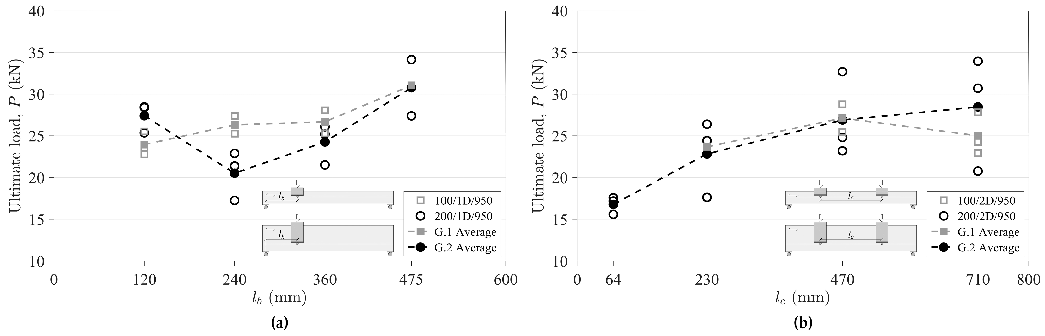
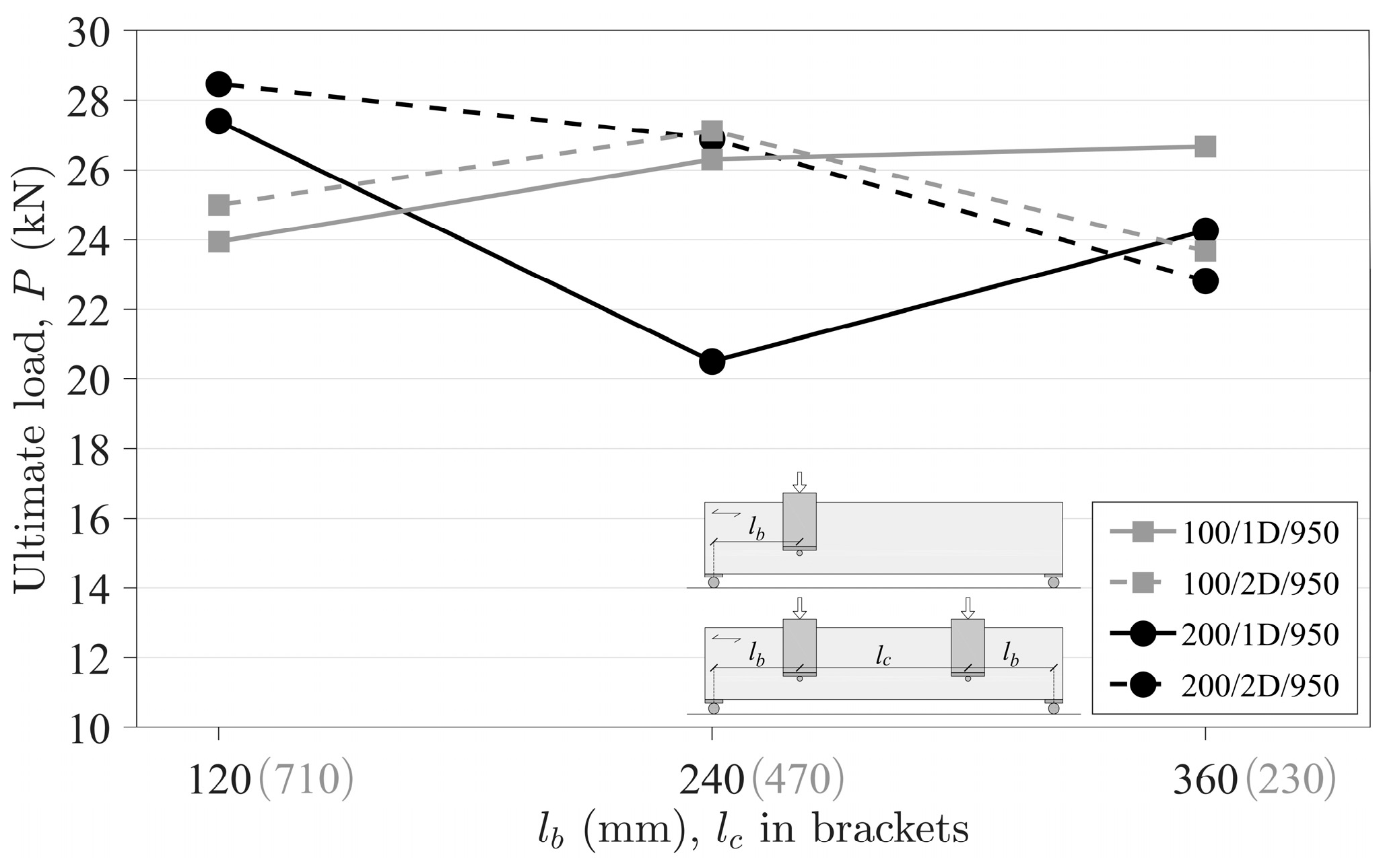
3.1.3. Influence of Distances lb and lc

The evolution of the maximum splitting load for the beams with one-dowel connections placed at different distances from the nearest support (lb) is shown in Figure 12a. Figure 12b shows the load evolution for beams with two-dowel connections as a function of the spacing between the dowels (lc). The results in both graphs are given for beams with h = 100 mm and h = 200 mm.
When looking at the evolution of the splitting capacity as a function of lb for beech beams with one-dowel connections (Figure 12a), the series of h = 200 mm shows a decrease in splitting failure loads with the proximity of the dowel to the support, up to the distance lb = 240 mm. However, the load increases again when the dowel is at the closest distance to the support of those studied (lb = 120 mm). The specific lb distance at which this trend change occurs is difficult to determine with accuracy as many tests would be necessary. However, a value of lbh seems a good approximation. This apparent increase in the splitting capacity of the beam may be due to the fact that, for distances of lbh, part of the load is transferred directly to the supports [62]. However, the splitting failure is not negligible even if lb < h.
A similar trend is observed for beams with h = 100 mm, with a decrease in ultimate load with decreasing lb, although in this case with no increase in load for the lowest lb. This observation may be related to the fact that the smallest value of lb tested is greater than h and therefore the dowel is not close enough to the support to transfer the load directly to it.
There are not many experimental studies in the literature focusing on the influence of lb. Some literature sources report that splitting capacity is independent of lb [35,61], contrary to the results of the present study, where the influence was evident. Other studies with off-centre dowel connections in sawn spruce, spruce glulam, Douglas fir glulam, or Radiata pine LVL can be found in [28,34,69]. However, due to the limited results and geometries addressed, it is difficult to draw clear conclusions.
When comparing the test results between the two beam depths, it can be seen that the h = 100 mm series tends to attain higher splitting loads than the h = 200 mm series. This gain in load may be explained, to some extent, by the difference in the α ratios, so that the higher the α, the higher the ultimate load. This influence of the parameter α is in line with the findings described in Section 3.1.1.
Regarding the evolution of the ultimate splitting loads as a function of lc for beech beams with two-dowel connections (Figure 12b), it can be seen that the loads increase with the dowel spacing, which is in agreement with the test results reported in [34,36,66,67,70].
The results from the h = 200 mm series show that the ultimate loads measured for beams with small dowel spacings (lc = 4d) do not differ significantly from the loads reached for beams with a single dowel placed at mid-span, and the larger the dowel spacing, the higher the splitting load. Small increases in the lc spacing lead to load increases, but this tends to stabilise at large lc spacings. A similar trend is observed for the series with h = 100 mm, although many of the specimens in this series failed in bending (Table 4). It should be noted that the average values of the loads reached are practically identical between the two groups, except for the series with an lc spacing of 710 mm, where the specimens with h = 100 mm showed lower splitting capacity. In this case, it seems that α does not influence the ultimate load, even though the series with h = 100 mm have twice the α ratio of those with h = 200 mm.
It is interesting to note that series with lb/h < 2.4 failed by splitting and those with lb/h ≥ 2.4 were susceptible to fail by bending. Furthermore, when lb/h ≥ 4.40, the governing failure mode appears to be primarily bending. However, these values are influenced by the number of dowels with which the connection is loaded, as beams with two dowels can transfer more load to the beam before splitting occurs. This favours bending as the dominant failure mode.

3.1.4. Influence of the Number of Connections

The effect of placing another connection symmetrically to the centre of the beam is discussed here. Figure 13 shows the evolution of the load per connection as a function of lb for beams with single (1D) and double symmetrical (2D) connections, for the two groups of beam depths tested (100 and 200 mm). It is observed that the load of beams with a single connection is higher than that of beams with two connections in the case of lb of 360 mm, i.e., a connection spacing lc of 230 mm. Considering the linear relationship plotted in Figure 13, the value of lc required for a multiconnection beam to exceed the load corresponding to its single-connection counterpart would be approximately 420 mm and 280 mm for h = 100 mm and h = 200 mm, respectively (lc ≈ 4.2h and 1.4h, respectively). This could be due to an influence of the α parameter, suggesting that a higher α requires higher lc connection spacing.
In the case of beams with h = 100 mm, it is observed that the load per connection in beams with multiple connections corresponding to lb distances of 120 mm and 240 mm (lc ≥ 470 mm) is approximately 4% higher than the equivalent case with a single connection. However, in the case of beams with h = 200 mm, this increase does not remain constant and amounts to 4% and 31% for lb distances of 120 mm and 240 mm, respectively. In this case, there is a significant gain for lb = 240 mm. It should be noted that this distance lb corresponds to the geometry for which the most critical case of its equivalent with one connection occurs. In both groups of beam depths, for a certain distance between connections (lc), there is an inflexion point at which beams with multiple connections reach more load than their counterparts with a single connection. Therefore, a beam with multiple connections arranged symmetrically to the centre of the beam reaches more than twice the splitting load than its counterpart with a single connection.
According to the findings in Section 3.1.3, the total load of a beam with two dowels located at off-centre of the beam does not double the load of the reference connection, i.e., a connection with two dowels located at mid-span. However, when comparing similar geometries, there is a certain connection spacing (lc) where the stresses introduced into the beam by each connection do not interfere with each other and, in such cases, the total load of a beam with multiple connections can be more than twice the load of its counterpart with a single connection.

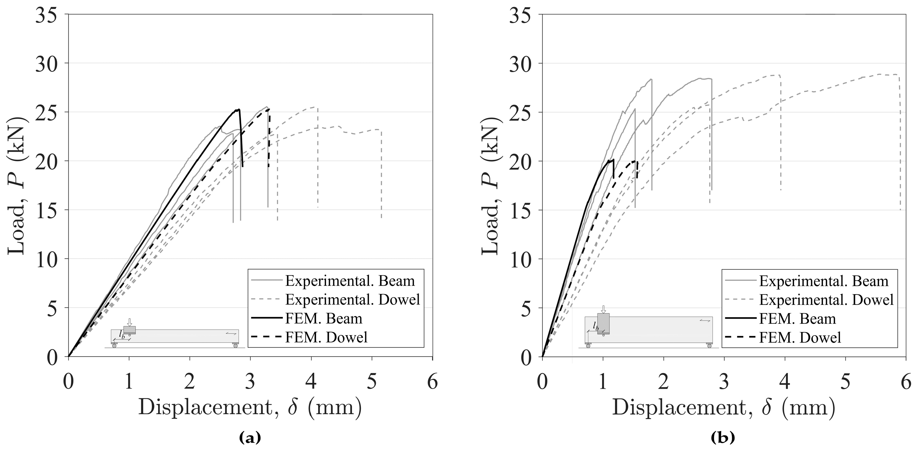
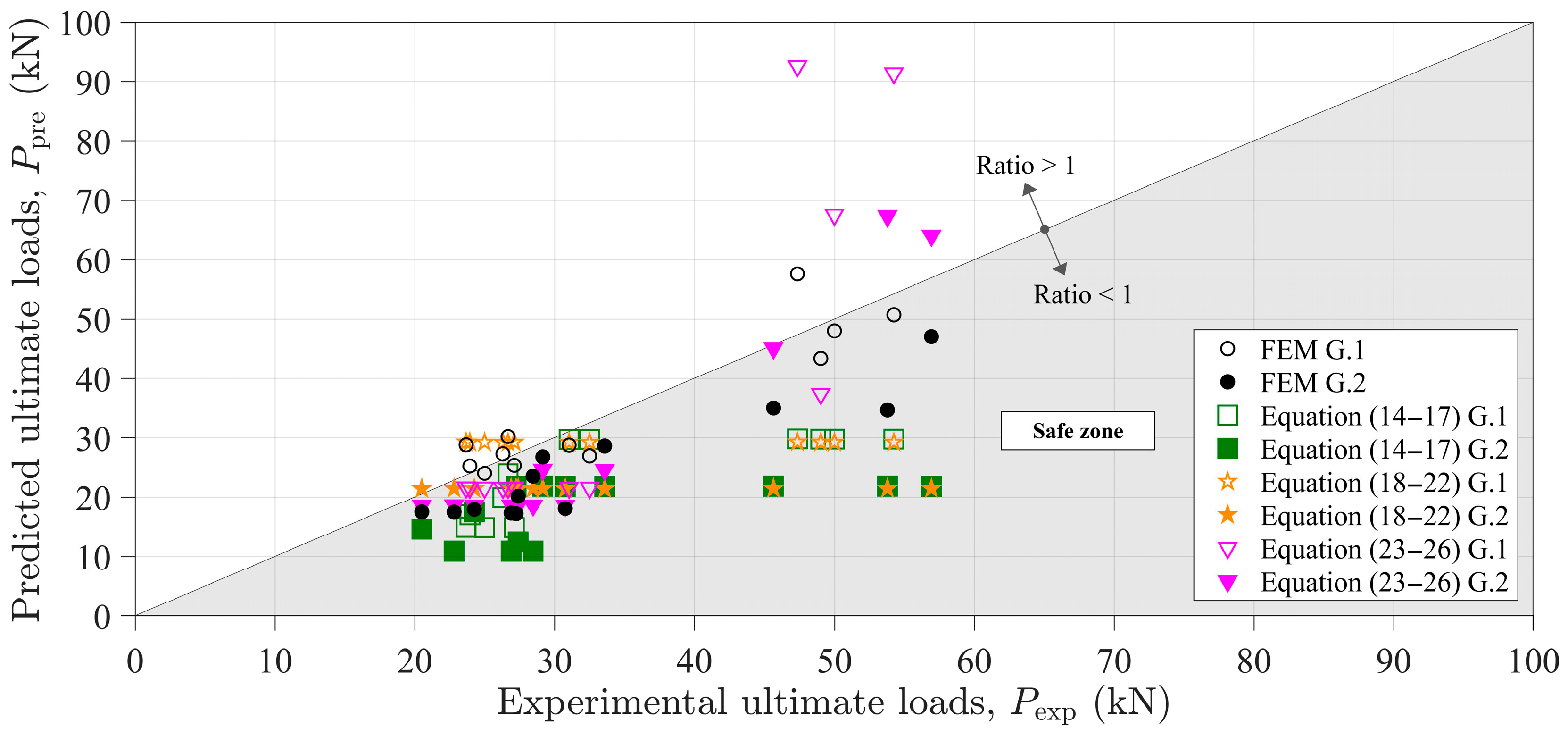
3.2. Comparison between Experimental, Numerical, and Theoretical Failure Loads

The adequacy of the numerical and design models described in Section 2.2 and Section 2.3 for the prediction of the splitting failure loads of beech beams loaded perpendicular to the grain by the connections is discussed here in relation to the experimental results. The material properties of the European beech used as input values in the models were also presented in Section 2.2, which corresponded to the tangential direction of the wood as this was the main orientation of the cross-section of the beams.
Figure 14 shows representative results of the experimental (grey lines) and numerical (black lines) load–displacement curves, depicting both the dowel displacement (dashed lines) and the beam bottom face displacement (solid lines). As can be seen, the numerical results agree well with the experimental results for the main parameters, such as stiffness and ultimate load. Still, the numerical curves were able to better reproduce the experimental behaviour of the beams with a brittle failure than those with a mixed-mode failure pattern (see Figure 5). The good agreement between the experimental and numerical initial stiffness shows that the average values of the elastic constants used are representative of the material. This consistency between the numerical and experimental initial stiffness is more evident in the curves plotted considering the displacement of the bottom of the beam than in those plotted with the displacement under the dowel, where the numerical ones show a higher stiffness. The maximum splitting capacity of the geometries of group 1 (h = 100 mm) matches the experimental results, but in the case of group 2 (h = 200 mm), the predicted loads are always lower than the experimental ones.
It should be highlighted that the expression in Eurocode 5 [24] focuses on the prediction of the maximum shear force, so the maximum splitting capacity of the connection has been obtained by applying beam theory. Thus, the maximum splitting capacity foreseen by Eurocode 5 [24] is twice the value of the shear force (Equations (14)–(17)) for all series, except for series 1D with the connection located at off-centre of the beam, where the maximum load carrying capacity was determined according to the following expression:
P pre = V s , max L L l b
where Vs,max is the maximum shear force obtained directly from Equation (14), L is the beam span, and lb is the distance from the connection to the nearest support. It should be noted that only Eurocode 5 [24] and the numerical models take into account the position of the connection with respect to the beam.
The results of the predicted failure loads from the numerical finite element analysis and the three design models studied are presented in Table 6. The predicted values normalised to the experimental results for all cases are also included. These ratios are also shown graphically in Figure 15. A ratio ≤ 1 represents a safe prediction and a ratio > 1 an unsafe prediction.
As can be seen from the results, in general terms, the best theoretical predictions were found for low experimental loads (between 20 and 35 kN), and there was more dispersion at higher experimental loads (between 45 and 60 kN).
When the connection is located at the centre of the beam (lb = 0.5L), all models provide safe predictions for all the cases studied (one and two dowels and the two beam edges). Specifically, in the case of one dowel (1D), the Eurocode 5 base model and the Jensen model similarly give the best predictions. However, when there are two dowels (2D), it is FEM that stands out with theoretical loads closer to the experimental ones when applying the three design models, and it is precisely the Eurocode 5 base model and Jensen that offer the worst predictions this time, contrary to the previous case. This is consistent with the models that do not consider the number of fasteners in their formulation.
When the connection is off-centre (lb = 0.38L, 0.25L, and 0.13L) and considering 1D, the Eurocode 5 model is the one that gives the predictions least adjusted to the experimental values in most cases, although always on the safe side. The closer the dowel is to the support, the more conservative it is. It should be noted that the C1 value used in the expression corresponds to beech. If the fixed value C1 = 14 given in the Eurocode 5 expression (Equations (14)–(17)) for softwoods had been used, the predicted loads would have been even more conservative.
In the case of off-centre connection, but focusing now on 2D, two assumptions have been considered for the analysis of results: each dowel as part of a separate connection (i.e., the beam would have two connections with 1D each) and the two dowels as part of the same connection. The results of this second assumption are marked with * in Table 6.
According to the first scenario of two separate connections, the Eurocode 5 model seems to be too conservative again, this time with predictions below 63% of the experimental load. The FEM appears to give theoretical values closer to the experimental ones.
Under the second assumption of considering the two dowels as part of the same connection, the theoretical failure loads predicted by the FEM and by the Eurocode 5 model double their value, but the ratio between these and the experimental ones is the same as that obtained under the first assumption, thus making the Eurocode 5 model quite conservative, as mentioned above.
However, the load ratios resulting from applying the models of Jensen (Equations (18)–(22)) and Franke and Quenneville (Equations (23)–(26)) differ between the two assumptions. Specifically, Jensen’s model leads to the same theoretical loads for both scenarios, and therefore, the ratios are halved when only one connection is considered, which means overly conservative predictions with theoretical values below 62% of the experimental load, similar to those obtained by applying the Eurocode 5 model (it should be remembered that both models disregard the number of dowels in the connection in their formulation). On the other hand, if the connections were considered independent, Jensen’s model gives results closer to the experimental ones but sometimes in a non-conservative way, as was the case for beams of h = 100 mm.
Focusing on the Franke and Quenneville model, the difference in behaviour between both assumptions is the reverse: the consideration of independent connections is the one that gives conservative results, while the second assumption of considering a single connection with two dowels results for most of the cases unsafe, with some theoretical values far away from the experimental ones, especially in the beams of h = 100 mm. Therefore, the Franke and Quenneville design model considering two independent connections, as well as the FEM model, would be the most appropriate when off-centre multidowel connections are presented.

4. Conclusions

The numerical and experimental splitting capacity results for European beech (Fagus sylvatica L.) beams loaded perpendicular to the grain by single- and double-dowel connections with different locations along the beam span are provided.
The use of an additional dowel slightly increases the splitting capacity at low α (he/h) values (0.32) but significantly increases it at high α values (0.64), by about 50%. For the same test configuration, the larger the beam span, the higher the splitting load. For single-dowel connections, the position of the dowel along the beam span influences the splitting capacity, which is lower the closer the connection is to the supports. For double-dowel connections, the greater the distance between the dowels, the greater the splitting load, but in no case will the increased load from an additional dowel double the ultimate load of a single-dowel connection. Beams with lb/h < 2.4 fail by splitting, and those with an lb/h ratio ≥ 2.4 are susceptible to fail by bending, but these values are influenced by the number of dowels loaded into the connection, as beams with two dowels can transfer more load to the beam before splitting occurs. This fact favours bending as the dominant failure mode.
A 2D finite element model was developed for each geometry in the experimental programme, using a cohesive element model and a bilinear cohesive law to reproduce the mode I and II fracture process.
The proposed finite element model successfully replicated the behaviour of beams exhibiting purely brittle failure patterns more effectively than those displaying mixed-mode failure.
The numerical P-δ curves are in good agreement with the experimental ones. The proposed numerical model demonstrates its efficacy as a powerful tool for predicting the splitting capacity of timber connections with various arrangements. Moreover, it proves to be structurally safe from a design standpoint.
Of the three design models based on fracture mechanics (including the Eurocode 5 expression), the models based on elastic and linear fracture energy generally give good load predictions for single-dowel arrangements. For two-dowel layouts, where the two dowels are considered as part of the same connection, design models that include fracture properties only in mode I provide too conservative values. The model that considers mode I and II fracture and the influence of joint width (lc) predicts overestimated values for high lc configurations.
Further experimental research on the splitting behaviour considering other connection geometries and hardwood species would be desirable in order to obtain a general expression valid for all of them.

Author Contributions

Conceptualisation, J.L.G.-R., A.J.L.-B. and A.M.-M.; methodology, J.L.G.-R., A.J.L.-B., A.M.-M., J.X. and M.F.S.F.d.M.; validation, J.L.G.-R.; formal analysis, J.L.G.-R.; investigation, J.L.G.-R., A.J.L.-B. and A.M.-M.; writing—original draft preparation, J.L.G.-R.; writing—review and editing, J.L.G.-R., A.J.L.-B., A.M.-M., J.X. and M.F.S.F.d.M.; visualisation, J.L.G.-R.; supervision, A.M.-M., J.X. and M.F.S.F.d.M.; funding acquisition, A.M.-M., J.X. and M.F.S.F.d.M. All authors have read and agreed to the published version of the manuscript.

Funding

Part of the work was undertaken during a short-term scientific stay by the first author at the Faculty of Engineering (University of Porto) in 2021, with the financial support provided by Programa Propio de I+D+i 2021 de la Universidad Politécnica de Madrid. This work is part of the R&D&I Project PID2020-112954RA-I00 funded by MCIN/AEI/10.13039/501100011033. The authors gratefully acknowledge Fundação para a Ciência e a Tecnologia (FCT-MCTES) for the financial support of the Laboratório Associado de Energia, Transportes e Aeronáutica (LAETA) by the project UID/EMS/50022/2020 and the Research and Development Unit for Mechanical and Industrial Engineering (UNIDEMI) by the projects UIDB/00667/2020 and UIDP/00667/2020.

Institutional Review Board Statement

Not applicable.

Informed Consent Statement

Not applicable.

Data Availability Statement

The original contributions presented in the study are included in the article material, further inquiries cab be directed to the corresponding author/s.

Conflicts of Interest

The authors declare no conflict of interest.

References

  1. Gustavsson, L.; Sathre, R. Variability in Energy and Carbon Dioxide Balances of Wood and Concrete Building Materials. Build. Environ. 2006, 41, 940–951. [Google Scholar] [CrossRef]
  2. UNEP. Buildings and Climate Change: Summary for Decision-Makers; UNEP DTIE, Sustainable Consumption & Production Branch: Paris, France, 2009; ISBN 987-9-28073-064-7. [Google Scholar]
  3. Buchanan, A.H.; Honey, B.G. Energy and Carbon Dioxide Implications of Building Construction. Energy Build. 1994, 20, 205–217. [Google Scholar] [CrossRef]
  4. Sathre, R.; Gustavsson, L. Using Wood Products to Mitigate Climate Change: External Costs and Structural Change. Appl. Energy 2009, 86, 251–257. [Google Scholar] [CrossRef]
  5. UNECE; FAO. Circularity Concepts in Wood Construction; United Nations Publication: Geneva, Switzerland, 2023; ISBN 978-9-21117-328-4. [Google Scholar]
  6. Aicher, S.; Christian, Z.; Dill-Langer, G. Hardwood Glulams—Emerging Timber Products of Superior Mechanical Properties. In Proceedings of the World Conference on Timber Engineering (WCTE), Quebec City, QC, Canada, 10–14 August 2014. [Google Scholar]
  7. Camú, C.T.; Aicher, S. A Stochastic Finite Element Model for Glulam Beams of Hardwoods. In Proceedings of the World Conference on Timber Engineering, Seoul, Republic of Korea, 20–23 August 2018. [Google Scholar]
  8. De Rigo, D.; Caudullo, G. Fagus Sylvatica in Europe: Distribution, Habitat, Usage and Threats. In European Atlas of Forest Tree Species; Publication Office of the European Union: Luxembourg, 2016; pp. 94–95. ISBN 978-9-27617-291-8. [Google Scholar]
  9. Antonucci, S.; Santopuoli, G.; Marchetti, M.; Tognetti, R.; Chiavetta, U.; Garfì, V. What Is Known About the Management of European Beech Forests Facing Climate Change? A Review. Curr. For. Rep. 2021, 7, 321–333. [Google Scholar] [CrossRef]
  10. Gómez-Royuela, J.L.; Majano-Majano, A.; Lara-Bocanegra, A.J.; Reynolds, T.P.S. Determination of the Elastic Constants of Thermally Modified Beech by Ultrasound and Static Tests Coupled with 3D Digital Image Correlation. Constr. Build. Mater. 2021, 302, 124270. [Google Scholar] [CrossRef]
  11. Ozyhar, T.; Hering, S.; Niemz, P. Viscoelastic Characterization of Wood: Time Dependence of the Orthotropic Compliance in Tension and Compression. J. Rheol. 2013, 57, 699–717. [Google Scholar] [CrossRef]
  12. Ozyhar, T.; Hering, S.; Sanabria, S.J.; Niemz, P. Determining Moisture-Dependent Elastic Characteristics of Beech Wood by Means of Ultrasonic Waves. Wood Sci. Technol. 2013, 47, 329–341. [Google Scholar] [CrossRef]
  13. Ozyhar, T.; Hering, S.; Niemz, P. Moisture-Dependent Orthotropic Tension-Compression Asymmetry of Wood. Holzforschung 2013, 67, 395–404. [Google Scholar] [CrossRef]
  14. Ozyhar, T.; Hering, S.; Niemz, P. Moisture-Dependent Elastic and Strength Anisotropy of European Beech Wood in Tension. J. Mater. Sci. 2012, 47, 6141–6150. [Google Scholar] [CrossRef]
  15. Widmann, R.; Fernandez-Cabo, J.L.; Steiger, R. Mechanical Properties of Thermally Modified Beech Timber for Structural Purposes. Eur. J. Wood Wood Prod. 2012, 70, 775–784. [Google Scholar] [CrossRef]
  16. Franke, S.; Magnière, N. The Embedment Failure of European Beech Compared to Spruce Wood and Standards. In Materials and Joints in Timber Structures; Aicher, S., Reinhardt, H.-W., Garrecht, H., Eds.; RILEM Bookseries; Springer: Dordrecht, The Netherlands, 2014; pp. 221–229. ISBN 978-9-40077-810-8. [Google Scholar]
  17. Gómez-Royuela, J.L.; Majano-Majano, A.; Lara-Bocanegra, A.J.; Xavier, J.; de Moura, M.F.S.F. Evaluation of R-Curves and Cohesive Law in Mode I of European Beech. Theor. Appl. Fract. Mech. 2022, 118, 103220. [Google Scholar] [CrossRef]
  18. Gómez-Royuela, J.L.; Majano-Majano, A.; Lara-Bocanegra, A.J.; Xavier, J.; de Moura, M.F.S.F. Shear Traction-separation Laws of European Beech under Mode II Loading by 3D Digital Image Correlation. Wood Sci. Technol. 2022, 56, 1631–1655. [Google Scholar] [CrossRef]
  19. Ehrhart, T.; Steiger, R.; Frangi, A. European Beech Glued Laminated Timber. Bautechnik 2021, 98, 104–114. [Google Scholar] [CrossRef]
  20. Blass, H.; Frese, M.; Enders-Comberg, M. Beech LVL—High Strength Material for Engineered Timber Structures. In Structures and Architecture: Beyond Their Limits, 1st ed.; Cruz, P.J., Ed.; CRC Press: Boca Raton, FL, USA, 2016; pp. 102–109. ISBN 978-1-31573-076-9. [Google Scholar]
  21. Lara-Bocanegra, A.J. Láminas Reticulares de Madera Deformadas Elásticamente. Del Material a La Construcción (In English: Elastic Timber Gridshells. From Material to Construction). Ph.D. Thesis, Universidad Politécnica de Madrid, Madrid, Spain, 2022. [Google Scholar] [CrossRef]
  22. Caldeira, T. Caracterização Experimental e Numérica Do Comportamento Frágil de Ligações Com Cavilhas Em Estruturas de Madeira (In English: Experimental and Numerical Characterisation of the Brittle Behaviour of Dowel Connections in Timber Structures). Ph.D. Thesis, Universidade de Trás-os-Montes e Alto Douro, Vila Real, Portugal, 2011. [Google Scholar]
  23. Franke, S.; Franke, B.; Heubuch, S.; Frangi, A.; Jockwer, R. Anschlüsse in Buchenholz. Ermittlung von Grundlagen Zur Bemessung von Anschlüssen Für Die Marktimplementierung in Der Schweiz; Berner Fachhochschule: Bern, Switzerland, 2019; ISBN 978-3-90687-806-5. [Google Scholar]
  24. EN 1995-1-1; Eurocode 5: Design of Timber Structures. Part 1-1: General. Common Rules and Rules for Buildings. European Committee for Standardization: Brussels, Belgium, 2016.
  25. Johansen, K.W. Theory of Timber Connections. Int. Assoc. Bridge Struct. Eng. 1949, 9, 249–262. [Google Scholar]
  26. Van der Put, T.A.C.M. Tension Perpendicular to the Grain at Notches and Joints. In Proceedings of the International Council for Research and Innovation in Building and Construction (CIB-W18), Lisbon, Portugal, 10–14 September 1990. [Google Scholar]
  27. Van der Put, T.A.C.M.; Leitjen, A.J.M. Evaluation of Perpendicular to Grain Failure of Beams Caused by Concentrated Loads of Joints. In Proceedings of the International Council for Research and Innovation in Building and Construction (CIB-W18), Delft, The Netherlands, 28–30 August 2000. [Google Scholar]
  28. Jensen, J.L.; Quenneville, P. Splitting of Beams Loaded Perpendicular to Grain by Connections. Some Issues with EC5. In Proceedings of the International Council for Research and Innovation in Building and Construction (CIB-W18), Alghero, Italy, 29 August–1 September 2011. [Google Scholar]
  29. Ballerini, M. A New Set of Experimental Tests on Beams Loaded Perpendicular to Grain by Dowel Type Joints. In Proceedings of the International Council for Research and Innovation in Building and Construction (CIB-W18), Graz, Austria, 23–25 August 1999. [Google Scholar]
  30. Möhler, K.; Lautenschläger, R. Groβflächige Queranschlüsse Bei Brettschichtholz; Forschungsbericht des Lehrstuhls für Ingenieurholzbau und Baukonstruktionen, Univ. Karlsruhe: Karlsruhe, Germany, 1978. [Google Scholar]
  31. Möhler, K.; Siebert, W. Ausbildung von Queranschlüssen Bei Angehängten Lasten an Brettschichtholzträger; Forschungsbericht des Lehrstuhls für Ingenieurholzbau und Baukonstruktionen, Univ. Karlsruhe: Karlsruhe, Germany, 1980. [Google Scholar]
  32. Ehlbeck, J.; Görlacher, R. Tragverhalten von Queranschlüssen Mittels Stahlblechformteilen, Insbesondere Balkenschuhen, Im Holzbau; Forschungsbericht der Versuchsanstalt für Stahl, Holz und Steine, Abt. Ingenieurholzbau, Univ. Karlsruhe: Karlsruhe, Germany, 1983. [Google Scholar]
  33. Ballerini, M. Beams Transversally Loaded by Dowel-Type Joints: Influence on Splitting Strength of Beam Thickness and Dowel Size. In Proceedings of the International Council for Research and Innovation in Building and Construction (CIB-W18), CO, USA, 11–14 August 2003. [Google Scholar]
  34. Schoenmakers, J.C.M. Fracture and Failure Mechanisms in Timber Loaded Perpendicular to the Grain by Mechanical Connections. Ph.D. Thesis, Technische Universiteit Eindhoven, Eindhoven, The Netherlands, 18 May 2010. [Google Scholar]
  35. Jensen, J.L.; Girhammar, U.A.; Quenneville, P.; Källsner, B. Splitting of Beams Loaded Perpendicular to Grain by Connections: Simple Fracture Mechanics Models. In Proceedings of the World Conference on Timber Engineering (WCTE), Auckland, New Zealand, 15–19 July 2012. [Google Scholar]
  36. Leijten, A.J.M. Splitting of Timber Beams Caused by Perpendicular to Grain Forces of Multiple Connections. Eng. Struct. 2018, 171, 10–14. [Google Scholar] [CrossRef]
  37. Franke, S.; Franke, B.; Quenneville, P. Analysis of the Failure Behaviour of Multiple Dowel-Type Connections Loaded Perpendicular to the Grain in LVL. In Proceedings of the World Conference on Timber Engineering (WCTE), Auckland, New Zealand, 16–19 July 2012. [Google Scholar]
  38. Hindman, D.P.; Finkenbinder, D.E.; Loferski, J.R.; Line, P. Strength of Sawn Lumber and Wood Composite Dowel Connections Loaded Perpendicular to Grain. I: NDS Design Equations. J. Mater. Civ. Eng. 2010, 22, 1217–1225. [Google Scholar] [CrossRef]
  39. Patel, M.C.; Hindman, D.P. Comparison of Single- and Two-Bolted LVL Perpendicular-to-Grain Connections. I: National Design Specification for Wood Construction Equations. J. Mater. Civ. Eng. 2012, 24, 339–346. [Google Scholar] [CrossRef]
  40. Majano-Majano, A.; Lara-Bocanegra, A.J.; Xavier, J.; Guaita, M. Splitting Capacity of Eucalyptus Globulus Beams Loaded Perpendicular to the Grain by Connections. Mater. Struct. 2022, 55, 147. [Google Scholar] [CrossRef]
  41. Franke, B.; Quenneville, P. Analyses of the Failure Behaviour of Transversely Loaded Dowel Type Connections in Wood. In Proceedings of the World Conference on Timber Engineering (WCTE), Trentino, Italy, 20–24 June 2010. [Google Scholar]
  42. Dourado, N.; Silva, F.G.A.; de Moura, M.F.S.F. Fracture Behavior of Wood-Steel Dowel Joints under Quasi-Static Loading. Constr. Build. Mater. 2018, 176, 14–23. [Google Scholar] [CrossRef]
  43. Shi, D.; Huang, H.; Li, N.; Liu, Y.; Demartino, C. Bolted Steel to Laminated Timber and Glubam Connections: Axial Behavior and Finite-Element Modeling. Int. J. Mech. Sci. 2023, 252, 108364. [Google Scholar] [CrossRef]
  44. Boström, L. Method of Determination of the Softening Behaviour of Wood and the Applicability of a Nonlinear Fracture Mechanics Model. Ph.D. Thesis, Lund University, Lund, Sweden, 1992. [Google Scholar]
  45. Franke, S.; Franke, B.; Magnière, N. Load Carrying Capacity of Cracked Beams. In Proceedings of the World Conference on Timber Engineering (WCTE), Vienna, Austria, 22–25 August 2016. [Google Scholar]
  46. Jensen, J.L.; Gustafsson, P.J.; Larsen, H.J. A Tensile Fracture Model for Joints with Rods or Dowels Loaded Perpendicular to Grain. In Proceedings of the International Council for Research and Innovation in Building and Construction (CIB-W18), Colorado, CO, USA, 11–14 August 2003. [Google Scholar]
  47. Franke, B.; Quenneville, P. Design Approach for the Splitting Failure of Dowel-Type Connections Loaded Perpendicular to Grain. In Proceedings of the International Council for Research and Innovation in Building and Construction (CIB-W18), Vancouver, BC, Canada, 26–29 August 2013. [Google Scholar]
  48. DIN 4074-5:2008; Strength Grading of Wood-Part 5: Sawn Hard Wood. DIN: Berlin, Germany, 2008. (In German)
  49. EN 1912:2012; Structural Timber. Strength Classes. Assignment of Visual Grades and Species. European Committee for Standardization: Brussels, Belgium, 2012.
  50. EN 13183-1:2002; Moisture Content of a Piece of Sawn Timber. Part 1: Determination by Oven Dry Method. European Committee for Standardization: Brussels, Belgium, 2002.
  51. EN 408:2010+A1:2012; Timber Structures. Structural Timber and Gluedlaminated Timber. Determination of Some Physical and Mechanical Properties. European Committee for Standardization: Brussels, Belgium, 2012.
  52. EN 384:2016+A1; Structural Timber. Determination of Characteristic Values of Mechanical Properties and Density. European Committee for Standardization: Brussels, Belgium, 2019.
  53. ABAQUS 2021 Documentation; Dassault Systèmes Simulia Corp.: Johnston, RI, USA, 2021.
  54. Gonçalves, J.P.M.; de Moura, M.F.S.F.; de Castro, P.M.S.T.; Marques, A.T. Interface Element Including Point-to-surface Constraints for Three-dimensional Problems with Damage Propagation. Eng. Comput. 2000, 17, 28–47. [Google Scholar] [CrossRef]
  55. Franke, B.; Quenneville, P. Numerical Modeling of the Failure Behavior of Dowel Connections in Wood. J. Eng. Mech. 2011, 137, 186–195. [Google Scholar] [CrossRef]
  56. McKenzie, W.M.; Karpovich, H. The Frictional Behaviour of Wood. Wood Sci. Technol. 1968, 2, 139–152. [Google Scholar] [CrossRef]
  57. Durão, L.M.P.; de Moura, M.F.S.F.; Marques, A.T. Numerical Simulation of the Drilling Process on Carbon/Epoxy Composite Laminates. Compos. Part A Appl. Sci. Manuf. 2006, 37, 1325–1333. [Google Scholar] [CrossRef]
  58. Silva, F.G.A.; de Moura, M.F.S.F.; Dourado, N.; Xavier, J.; Pereira, F.A.M.; Morais, J.J.L.; Dias, M.I.R. Mixed-Mode I+II Fracture Characterization of Human Cortical Bone Using the Single Leg Bending Test. J. Mech. Behav. Biomed. Mater. 2016, 54, 72–81. [Google Scholar] [CrossRef]
  59. Davila, C.; Camanho, P.; de Moura, M.F. Mixed-Mode Decohesion Elements for Analyses of Progressive Delamination. In Proceedings of the 19th AIAA Applied Aerodynamics Conference, Reston, VA, USA, 16–19 April 2001. [Google Scholar]
  60. Jockwer, R.; Dietsch, P. Review of Design Approaches and Test Results on Brittle Failure Modes of Connections Loaded at an Angle to the Grain. Eng. Struct. 2018, 171, 362–372. [Google Scholar] [CrossRef]
  61. Jensen, J.L.; Quenneville, P.; Girhammar, U.A.; Källsner, B. Brittle Failures in Timber Beams Loaded Perpendicular to Grain by Connections. J. Mater. Civ. Eng. 2015, 27, 4015026. [Google Scholar] [CrossRef]
  62. Leijten, A.J.M.; Jorissen, A.J.M. Splitting Strength of Beams Loaded by Connections Perpendicular to Grain, Model Validation. In Proceedings of the International Council for Research and Innovation in Building and Construction (CIB-W18), Venice, Italy, 22–24 August 2001. [Google Scholar]
  63. Jensen, J.L. Splitting Strength of Beams Loaded by Connections. In Proceedings of the International Council for Research and Innovation in Building and Construction (CIB-W18), CO, USA, 11–14 August 2003. [Google Scholar]
  64. Jensen, J.L. Splitting Strength of Beams Loaded Perpendicular to Grain by Dowel Joints. J. Wood Sci. 2005, 51, 480–485. [Google Scholar] [CrossRef]
  65. Ballerini, M. A New Prediction Formula for the Splitting Strength of Beams Loaded by Dowel-Type Connections. In Proceedings of the International Council for Research and Innovation in Building and Construction (CIB-W18), Edinburgh, Scotland, 31 August–3 September 2004. [Google Scholar]
  66. Habkirk, R.; Quenneville, J.H.P. Bolted Wood Connections Loaded Perpendicular-to-Grain: Effect on Wood Species. In Proceedings of the World Conference on Timber Engineering (WCTE), Portland, OR, USA, 6–10 August 2006. [Google Scholar]
  67. Reshke, R.G. Bolted Timber Connections Loaded Perpendicular-to-Grain. Influence of Joint Configuration Parameters on Strength. Ph.D. Thesis, Royal Military College of Canada, Kingston, ON, Canada, 11 May 1999. [Google Scholar]
  68. Yasumura, M. Criteria for Damage and Failure of Dowel-Type Joints Subjected To Force Perpendicular To the Grain. In Proceedings of the International Council for Research and Innovation in Building and Construction (CIB-W18), Venice, Italy, 22–24 August 2001. [Google Scholar]
  69. Jensen, J.L.; Quenneville, P.; Girhammar, U.A.; Källsner, B. Beams Loaded Perpendicular to Grain by Connections—Combined Effect of Edge and End Distance. In Proceedings of the International Council for Research and Innovation in Building and Construction (CIB-W18): Meeting Forty-Five, Växjö, Sweden, 27–30 August 2012. CIB-W18/45-7-2. [Google Scholar]
  70. Kasim, M.; Quenneville, P. Effect of Row Spacing on the Capacity of Bolted Timber Connections Loaded Perpendicular-to-Grain. In Proceedings of the International Council for Research and Innovation in Building and Construction (CIB-W18), Kyoto, Japan, 16–19 September 2002. [Google Scholar]
Figure 1. Bending test set-ups.
Applsci 14 00900 g001
Figure 2. Experimental configurations tested: reference configurations (in red) with one- and two-dowel connections placed at mid-span for each beam depth group and variations (in grey) regarding connection position and beam slenderness.
Applsci 14 00900 g002
Figure 3. Numerical model: (a) single connection; (b) double connection.
Applsci 14 00900 g003
Figure 4. Bilinear cohesive law in mixed−mode I + II implemented in ABAQUS. Separation (δ) and traction (f).
Applsci 14 00900 g004
Figure 5. Governing failure modes in the experimental tests.
Applsci 14 00900 g005
Figure 6. Experimental P-δ curves of beams with one dowel: (a) 1D with connection at mid-span; (b) 1D with the connection placed at off-centre of the beam.
Applsci 14 00900 g006
Figure 7. Experimental P-δ curves of beams with two dowels: (a) 2D with connection at mid-span; (b) 2D with the connection placed at off-centre of the beam.
Applsci 14 00900 g007
Figure 8. Typical failures: (a) straight and continuous crack; (b) oblique and discontinuous crack.
Applsci 14 00900 g008
Figure 9. Typical crack patterns.
Applsci 14 00900 g009
Figure 10. Typical splitting failure of series with h = 100 mm (group 1 (ad)) and h = 200 mm (group 2 (eh)): (a,e) 1D with connection at mid-span; (b,f) 1D with the connection placed at off-centre of the beam; (c,g) 2D with connection at mid-span; (d,h) 2D with the connections placed at off-centre of the beam.
Applsci 14 00900 g010
Figure 11. Splitting failure loads for one- and two-dowel connections in relation to beam span, for h = 200 mm.
Applsci 14 00900 g011
Figure 12. (a) Splitting failure loads of single-dowel connections versus the distance between the connection and the support lb, for the two different beam depths; (b) splitting failure loads of two-dowel connections versus dowel spacing lc, for the two different beam depths.
Applsci 14 00900 g012
Figure 13. Splitting failure load per connection for single and double symmetrical connections as a function of the distance to the support lb, for the two different beam depths.
Applsci 14 00900 g013
Figure 14. Representative experimental and numerical P-δ curves: (a) series with h = 100 mm (100/1D/950/0.13L); (b) series with h = 200 mm (200/1D/950/0.13L).
Applsci 14 00900 g014
Figure 15. Experimental failure loads versus values predicted by FEM (black symbols) and by the design models (symbols in colours) for the European beech.
Applsci 14 00900 g015
Table 1. Experimental test program.
Number
of Dowels
Span
L
Connection–Support
Distance
SeriesNumber
of
Specimens
Density
ρ
Moisture
Content
Connection
Spacing
α
(no.dowels)(mm)lb (mm)h/no.dowels/L/lb(kg/m3)(%)lc (mm)he/h
Group 1
(h: 100 mm)
1D450225100/1D/450/0.5L47479.7-0.64
950475100/1D/950/0.5L473411.1
360100/1D/950/0.38L370810.4
240100/1D/950/0.25L372710.4
120100/1D/950/0.13L373010.1
2D450225100/2D/450/0.5L472710.2-0.64
950475100/2D/950/0.5L471010.7
360100/2D/950/0.38L374810.7230
240100/2D/950/0.25L373811.5470
120100/2D/950/0.13L371710.9710
Group 2
(h: 200 mm)
1D450225200/1D/450/0.5L47569.7-0.32
950475200/1D/950/0.5L374410.0
360200/1D/950/0.38L37169.7
240200/1D/950/0.25L373010.1
120200/1D/950/0.13L37589.9
2D450225200/2D/450/0.5L47309.6-0.32
950475200/2D/950/0.5L471310.0
360200/2D/950/0.38L374110.0230
240200/2D/950/0.25L374210.9470
120200/2D/950/0.13L371610.3710
Table 2. Average values and standard deviation of the elastic constants of European beech [10].
EL
(N/mm2)
ER
(N/mm2)
ET
(N/mm2)
νRL
(-)
νTL
(-)
νRT
(-)
GLR
(N/mm2)
GLT
(N/mm2)
GRT
(N/mm2)
Average13,81115908320.510.440.321108706349
St. Dev.13235411150.0300.0150.04120213953
Table 3. Numerical parameters of the bilinear cohesive law: maximum traction (fu) and critical fracture energy (Gc) in fracture modes I and II and TL crack propagation system for beech [17,18].
fI,u
(N/mm2)
fII,u
(N/mm2)
GIc
(N/mm)
GIIc
(N/mm)
Average8.7418.880.461.17
St. Dev.1.973.340.100.26
Table 4. Experimental results: percentage of beams with splitting/bending failure per series (%); average values of the connection failure load (Pexp) and the maximum shear force corresponding to the Pexp (Vshear,max) for each failure mode; coefficient of variation (COV); ratio between the distance of the connection to the support (lb) and the beam depth (h).
Failure Mode
SeriesSplitting/Bending
h/no.dowels/L/lb%Pexp (kN)Vshear.max (kN)COV (%)lb/h
Group 1
(h: 100 mm)
100/1D/450/0.5L100/-32.5/-16.3/-5.1/-2.25
100/1D/950/0.5L25/7531.0/30.315.5/15.2-/4.14.75
100/1D/950/0.38L67/3326.7/33.316.6/20.77.4/03.60
100/1D/950/0.25L67/3326.3/28.319.7/21.15.7/02.40
100/1D/950/0.13L100/-23.9/-20.9/-6.0/-1.20
100/2D/450/0.5L100/-49.0/-24.5/-10.5/-1.93
100/2D/950/0.5L-/100-/37.6-/18.8-/84.43
100/2D/950/0.38L33/6723.7/23.923.7/23.90/0.43.60
100/2D/950/0.25L67/3327.1/21.527.1/21.58.7/02.40
100/2D/950/0.13L100/-25.0/-25.0/-10.1/-1.20
Group 2
(h: 200 mm)
200/1D/450/0.5L100/-27.2/-13.6/-7.8/-1.13
200/1D/950/0.5L100/-30.8/-15.4/-11/-2.38
200/1D/950/0.38L100/-24.3/-15.1/-10.0/-1.80
200/1D/950/0.25L100/-20.5/-15.3/-14.2/-1.20
200/1D/950/0.13L100/-27.4/-23.9/-6.5/-0.60
200/2D/450/0.5L100/-29.2/-14.6/-20.5/-0.97
200/2D/950/0.5L100/-33.6/-16.8/-5.1/-2.22
200/2D/950/0.38L100/-22.8/-22.8/-20.1/-1.80
200/2D/950/0.25L100/-26.9/-26.9/-18.9/-1.20
200/2D/950/0.13L100/-28.5/-28.5/-24.1/-0.60
Table 5. Load increase in series with two-dowel connections compared to one-dowel connections.
Number of
Dowels
(no.dowels)
Series
h/no.dowels/L/lb
L
(mm)
Slenderness
(L/h)
he
(mm)
α
he/h
Pexp
(kN)
Load Increase
(%)
1D100/1D/450/0.5L4504.50640.6432.551%
2D100/2D/450/0.5L49.0
1D200/1D/450/0.5L4502.25640.3227.27%
2D200/2D/450/0.5L29.2
1D200/1D/950/0.5L9504.75640.3230.89%
2D200/2D/950/0.5L33.6
Table 6. Experimental (Pexp) vs. predicted (numerical and theoretical, Ppre) splitting capacity.
SeriesExp.
Test
Numerical
Analysis
Design Models
Eurocode 5 [24]
Equations (14)–(17)
Jensen [46]
Equations (18)–(22)
Franke and Quenneville [47]
Equations (23)–(26)
h/no.dowels/L/lbPexp
(kN)
Ppre
(kN)
Ppre/PexpPpre
(kN)
Ppre/PexpPpre
(kN)
Ppre/PexpPpre
(kN)
Ppre/Pexp
G.1100/1D/450/0.5L32.527.00.8329.80.9229.20.9021.60.66
100/1D/950/0.5L31.028.80.9329.80.9629.20.9421.60.70
100/1D/950/0.38L26.730.21.1324.00.9029.21.1021.60.81
100/1D/950/0.25L26.327.31.0419.90.7629.21.1121.60.82
100/1D/950/0.13L23.925.31.0617.00.7129.21.2221.60.90
100/2D/450/0.5L49.043.40.8929.80.6129.30.6037.40.76
100/2D/950/0.5L---------
100/2D/950/0.38L23.728.81.2214.90.6329.31.2421.60.91
100/2D/950/0.25L27.125.40.9414.90.5529.21.0821.60.80
100/2D/950/0.13L25.024.00.9614.90.6029.21.1721.60.86
G.1 *
(P = 2P)
100/2D/950/0.38L47.357.61.2229.80.6329.30.6292.61.96
100/2D/950/0.25L54.250.70.9429.80.5529.20.5491.41.69
100/2D/950/0.13L50.048.00.9629.80.6029.20.5867.61.35
G.2200/1D/450/0.5L27.217.20.6321.80.8021.40.7918.60.68
200/1D/950/0.5L30.818.10.5921.80.7121.40.7018.60.60
200/1D/950/0.38L24.317.90.7417.60.7221.40.8818.60.77
200/1D/950/0.25L20.517.50.8514.60.7121.41.0518.60.91
200/1D/950/0.13L27.420.20.7412.50.4621.40.7818.60.68
200/2D/450/0.5L29.226.80.9221.80.7521.50.7424.70.85
200/2D/950/0.5L33.628.60.8521.80.6521.40.6424.60.73
200/2D/950/0.38L22.817.50.7710.90.4821.50.9418.60.82
200/2D/950/0.25L26.917.30.6410.90.4121.50.8018.60.69
200/2D/950/0.13L28.523.50.8310.90.3821.40.7518.60.65
G.2 *
(P = 2P)
200/2D/950/0.38L45.635.00.7721.80.4821.50.4745.10.99
200/2D/950/0.25L53.834.70.6421.80.4121.50.4067.41.25
200/2D/950/0.13L56.947.10.8321.80.3821.40.3864.11.13
* This comparison is made considering that the beam has only one connection, i.e., P = 2P.
Disclaimer/Publisher’s Note: The statements, opinions and data contained in all publications are solely those of the individual author(s) and contributor(s) and not of MDPI and/or the editor(s). MDPI and/or the editor(s) disclaim responsibility for any injury to people or property resulting from any ideas, methods, instructions or products referred to in the content.

