Article

Research on the Characteristics of Seepage Failure in the Surrounding Rock (Coal) of the Goafs

1
College of Environment and Ecology, Taiyuan University of Technology, Taiyuan 030024, China
2
School of Earth Science and Engineering, Sun Yat-sen University, Zhuhai 519082, China
3
School of Resources and Geosciences, China University of Mining and Technology, Xuzhou 221116, China
*
Authors to whom correspondence should be addressed.
Appl. Sci. 2024, 14(20), 9210; https://doi.org/10.3390/app14209210
Submission received: 2 August 2024 / Revised: 29 September 2024 / Accepted: 30 September 2024 / Published: 10 October 2024

Abstract

:
During mining, the brittle fracture structure of coal makes it highly susceptible to disturbance, leading to changes in the permeability of the coal seam from non-conductive to water-conductive, which poses a significant threat to the stability and safety of coal pillars in goafs. Therefore, understanding the damage mechanisms of coal during water–rock interactions is crucial for ensuring mine safety. In this paper, based on laboratory seepage tests, the impact of hydrodynamic forces on the microstructure of fissured coal and its subsequent effect on permeability is examined. The study found that increasing confining pressure causes the “closure” of coal fissures, leading to a reduction in permeability. Additionally, during the initial stage of seepage, fine particles within the coal samples are mobilized due to seepage damage, leading to channel blockages and further reductions in permeability. However, as seepage continues, the hydraulic channels eventually open fully, resulting in a sharp increase in permeability. Furthermore, using a two-dimensional fracture seepage model, the study investigated how the scale of fractures in the water-conducting channels influences seepage behavior. A critical fracture width method was proposed to predict permeability surges, offering a new approach for analyzing the stability of coal pillars in mining areas.

1. Introduction

The study of waterproof coal pillars dates back to the 1950s, when B.Д.Cпecapeв developed a foundational theory on the topic [1,2]. In the 1980s, British scholars investigated the position of coal pillar fractures in the mining face and their impact on permeability [3]. Through in situ permeability tests that involved injecting water into sealed sections and observing water pressure and flow rate, they concluded that coal bodies are permeable. Their findings indicated that the required width of coal pillars in British mining areas should be no less than 40 yards (37 m) to ensure stability [4]. Subsequent studies have built upon these foundational findings. Sun et al. [5], through numerical simulation, demonstrated that water pressure irreversibly alters the permeability and porosity of coal, emphasizing the processes of water compression, storage, and adsorption within the coal seam. Some scholars have observed that during permeability tests, fine particles within the coal body migrate, leading to creep behavior and a reduction in permeability [6,7,8]. Du et al. [9], further noted that coal samples—whether intact, fractured, or broken—show regular changes in permeability when subjected to seepage pressure and axial load.
In another key development, Lin and Yao et al. [10,11], proposed an empirical formula for the permeability of raw coal by encasing coal samples in phenolic resin. Wen et al. [12], Huang et al. [13], and Zhang et al. [14] revealed that prolonged water immersion loosens the pore structure of coal, particularly at room temperature (25 °C). Lu et al. [15,16] explored the microstructural evolution of coal pores under water injection pressure, findings that are critical for enhancing deep-seated coalbed methane extraction. Scholars such as Perera et al. [17], Zhou et al. [18], and Liu et al. [19] have also demonstrated that moisture content significantly impacts the mechanical properties of coal, which decrease progressively as moisture increases.
In practice, the softening of coal pillars due to water exposure has also been observed. Sun et al. [5], in their research on coal pillar protection in goafs, found that the tensile and compressive strengths of coal samples from the No. 7 coal seam in the Pengzhuang Mine decreased significantly after three weeks of groundwater immersion, before stabilizing. In acidic environments within old goafs, the coal pillar strength reduction coefficient can reach as low as 0.6 [20]. Based on these observations, researchers have modified the original coal pillar size calculation formula to account for a weakening coefficient. Liu et al. [21] and Chen et al. [22] analyzed the influence of groundwater seepage on coal seam strength, highlighting that the seepage–stress coupling effect is a critical factor in determining coal pillar stability. Huang et al. [23] added that the critical size of coal pillars is influenced by factors such as the depth of coal seam burial, as well as the structure and characteristics of the roof and floor strata. Chen et al. [22] and Fan et al. [24] also noted that seepage can erode fissure channels, thereby weakening coal pillar integrity, while Jia et al. [25] and Guo et al. [26] pointed out that mining-induced fissures in the overburden rock can significantly alter the mechanical properties of the coal seam when exposed to water.
Despite the wealth of research on coal pillar stability, most studies have focused on roadways or coal pillars within mining faces, with fewer investigations into the effects of water seepage in water-filled goaf areas. Goaf areas with accumulated water present a unique challenge, as coal pillars exposed to water for extended periods can become unstable, potentially leading to the collapse of mining sections or the rapid inflow of water from goaf areas into other parts of the mine. These situations pose severe economic and safety risks.
Given these challenges, it is essential to further explore the mechanisms of seepage damage in coal pillars within water-filled goaf areas. Understanding the interaction between water and rock in these conditions is crucial for developing a scientific basis for determining the appropriate size and characteristics of waterproof coal pillars, thus ensuring the safety and stability of mining operations. This study aims to provide theoretical support for the evaluation and prevention of water-related hazards in coal mines, particularly in the context of water–rock interactions in goaf areas.

2. Materials and Methods

2.1. Preparation of Coal Samples

The sampling location for this study is the Xishan Coalfield in Shanxi Province (as shown in Figure 1). The mining area is located in the northwestern part of Taiyuan City, Shanxi Province. The overall structural morphology consists of alternating anticline and syncline folds, with the strike and dip controlled by these fold structures. The dip angle of the strata ranges from 2° to 12°, generally around 6°. The main coal seams being mined are coal seam No. 2 and coal seam No. 8. The water-bearing rock formations in this area include the Quaternary Holocene gravel aquifer, the Permian Upper Shiqianfeng Formation sandstone fissure aquifer, the Upper Shihezi Formation sandstone fissure aquifer, the Permian Lower Shihezi Formation sandstone fissure aquifer, the Shanxi Formation sandstone fissure aquifer, the Carboniferous Upper Taiyuan Formation limestone karst fissure aquifer, the Ordovician Middle Fengfeng Formation limestone karst fissure aquifer, and the Upper Majiagou Formation limestone karst fissure aquifer. Mudstone and carbonate layers, where karst and fissures are underdeveloped, act as aquitards between these bedrock aquifers, preventing hydraulic connection or allowing only weak hydraulic connection between the various aquifer groups. These layers serve as aquicludes or relatively impermeable layers.
To ensure the accuracy of the measured permeability during permeability tests, the coal sample surfaces were treated to prevent leakage between the sample surface and the pipe wall. The coal samples were cleaned to remove dust and impurities and wrapped with PTFE (polytetrafluoroethylene) waterstop tape to minimize boundary leakage. Due to the development of endogenous joints and fractures in the coal, the rock samples often became fragmented during sampling. Consequently, cylindrical coal samples with a diameter of approximately 25 mm and a length of approximately 30 mm were obtained using a coring drill bit, and a total of 10 coal samples were prepared for the experiment (Table 1). The ends of the coal samples were polished to ensure smooth and flat surfaces, ensuring tight contact with the sealing heads during permeability tests and uniform stress distribution during axial compression tests. Maintaining the integrity and good sealing of the coal sample structure provided a reliable guarantee for obtaining stable seepage data. The characteristic parameters of the coal samples are shown in the table below.

2.2. Experimental Principles and Procedures

Permeability (k) is one of the main parameters for studying the permeability of rock formations, representing the permeability of coal rock. From the perspective of coal rock damage, permeability can be considered the dislocation and fracture of bonding bonds at the micro-level, the expansion and penetration of microcracks at the meso-level, and changes in mechanical behavior at the macro-level. The stress changes experienced by coal rock are usually accompanied by a damage process [27,28,29,30,31].
In this study, a seepage system was used to test 10 selected sets of coal samples. To express the permeability performance in the experiment, the coal samples were assumed to be equivalent to a porous medium with the same cross-sectional area, uniformly distributed, in accordance with the experimental assumptions of Darcy’s law [32,33]:
Q = k Δ p S η L
where Q is the flow rate; S is the cross-sectional area of the coal sample; L is the length of the coal sample; η is the viscosity coefficient of the fluid; k is the permeability of the coal sample; and ΔP is the pressure difference between the upstream and downstream of the test sample.
Permeability can be measured in two ways: one is by applying a stable pressure difference ΔP at the upstream and downstream ends of the coal sample and measuring the flow rate Q through the sample to obtain the permeability; the other is by giving a certain flow rate Q and then calculating the permeability based on the pressure difference ΔP between the upstream and downstream. In this experiment, a stable flow rate injection method was used to obtain the parameters (Table 2).
The steps of the experiment are as follows:
  • Check the Instrument: Before inserting the core, check the instrument to ensure that the confining pressure has been released, remove the end caps, and ensure that there are no cores or spacers in the holder. Prepare for the experiment.
  • Insert the Coal Sample: Wrap the prepared coal sample with waterstop tape and insert it into the holder. Fix the end caps with two protruding clips, aligning them with the grooves on the end cover, and rotate clockwise about 1/4 turn until it cannot be turned further, ensuring the position is fixed while tightening the adjustment cap.
  • Insert Spacers: Insert appropriate length spacers based on the coal sample length (30 mm), ensuring the total length of the core and spacers is within 80–100 mm.
  • Check Sealing: After inserting the test sample, turn the adjustment sleeve counterclockwise by hand. If it moves easily, tighten it further. Ensure the sleeve is tight and not easy to move, completing the inspection.
  • Apply Confining Pressure: Manually pressurize the confining pressure pump. After loading the confining pressure, check the stability and reliability of the seepage system. If there is any pressure relief, check for leaks and repair them promptly to ensure the instrument works properly.
  • Inject Water Flow: Turn on the water injection system, slowly permeate the sample with a constant flow rate of 1 mL/min, observe for leaks, and simultaneously turn on the data acquisition system and zero it, recording data in real-time.
  • Set Monitoring System: Set various parameters as required and save the data promptly to prevent data loss.
  • Export and Analyze Data: After the experiment, export and save the data promptly and perform data analysis.

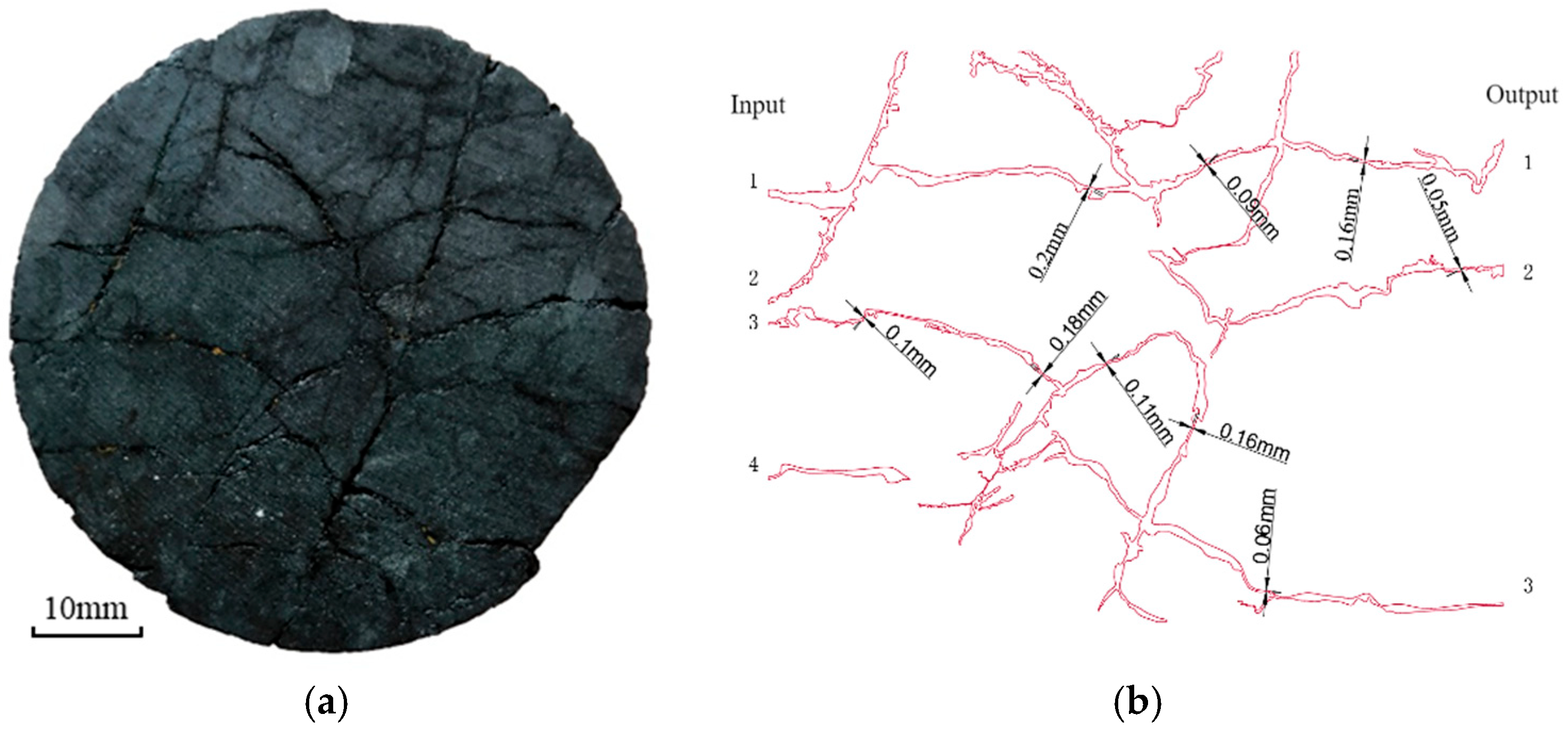
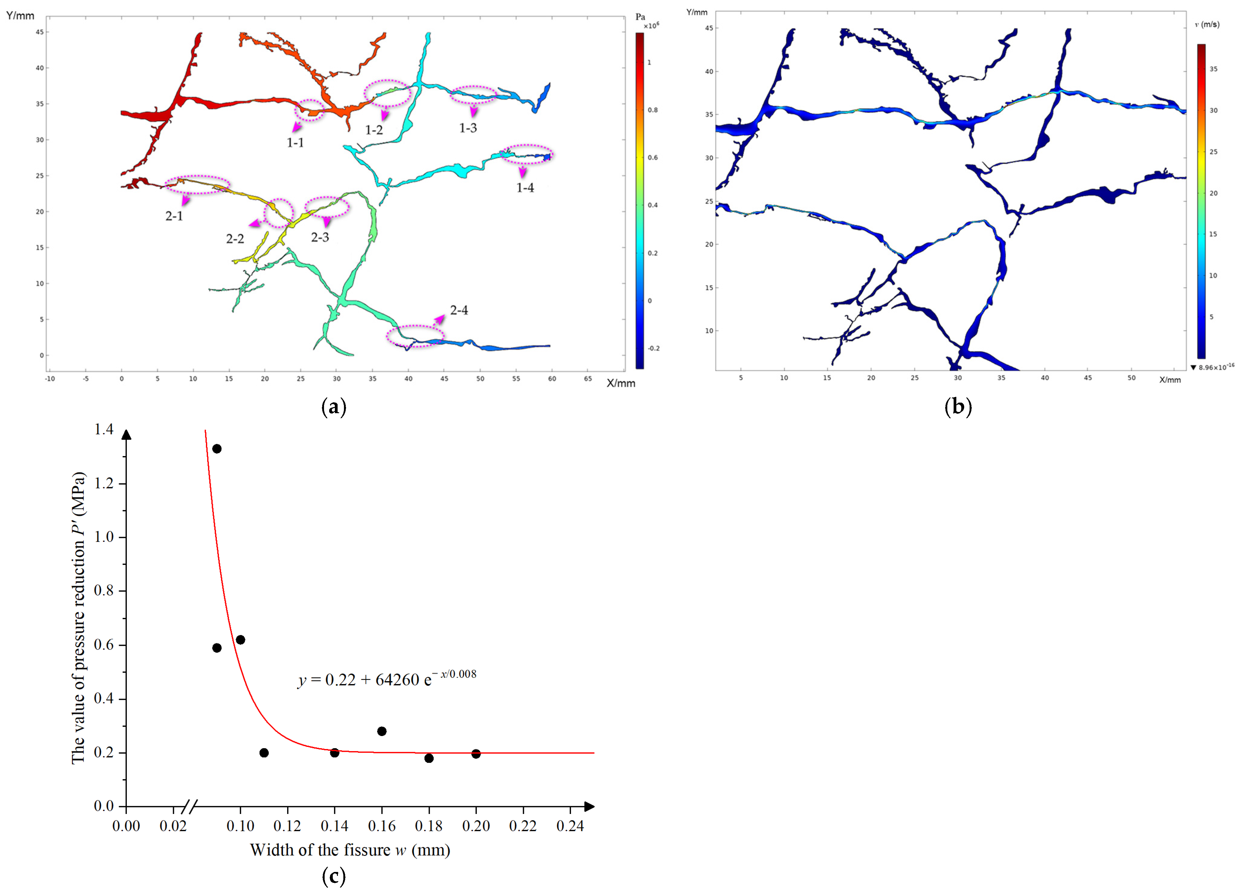
2.3. Method of Simulation of Fissure Seepage

Water inrush in mined-out areas of coal mines is caused by mining activities that induce the expansion and connectivity of pores and fractures within the coal rock, leading to coal rock damage. This ultimately causes the excavation space to connect with the water-filled areas, resulting in water inrush. Due to the difficulty of directly observing the process of coal seam damage and fracture under the coupled effects of seepage and stress during water inrush, we investigate the characteristics of fracture seepage in coal samples through a generalized study of localized fractures. This study uses coal samples containing mesoscopic fractures to build a model (Figure 2) and simulate the flow process, analyzing the changes in flow velocity and pressure within the coal sample fractures.
The geometric dimensions of the model are 60 mm wide and 45 mm high, with the left side serving as the flow input. From top to bottom, the inlets are designated as input 1, input 2, input 3, and input 4, with inlet 4 having no outlet and thus being negligible. The focus is on the fluid conditions flowing through the fractures from the first three inlets to outputs 1, 2, and 3 (Figure 3). To enhance the visualization of the results, the inlet pressure is set at 2 MPa, the outlet pressure at 0 MPa, with the fluid density ρ set at 1000 kg/m3 and dynamic viscosity μ at 0.001 Pa·s.
The model considers the change in the Reynolds number of the fluid as it flows through different parts of the fractures, caused by variations in fracture scale. To describe the distribution of fluid states, a turbulence model is used, with the fluid property equations described as follows:
ρ u u = [ p I + K ] + F ρ u = 0 K = μ + μ T u + ( u ) T ρ u k = [ ( μ + μ T σ k ) k ] + P k ρ ε ρ u ε = [ ( μ + μ T σ ε ) ε ] + C ε 1 ε k P k C ε 2 ρ ε 2 k , ε = e p
where ρ represents the density of the material in kg/m3; u is the seepage velocity of the fluid in m/s; K is hydrodynamic conductivity; I is the unit diagonal matrix; P is the pressure in MPa; ∇ is the differential operator; μ is the dynamic viscosity of the fluid in Pa·s; F is the body force in N/m3; ε is strains; and k is the turbulent kinetic energy in m2/s2.

3. Results and Discussion

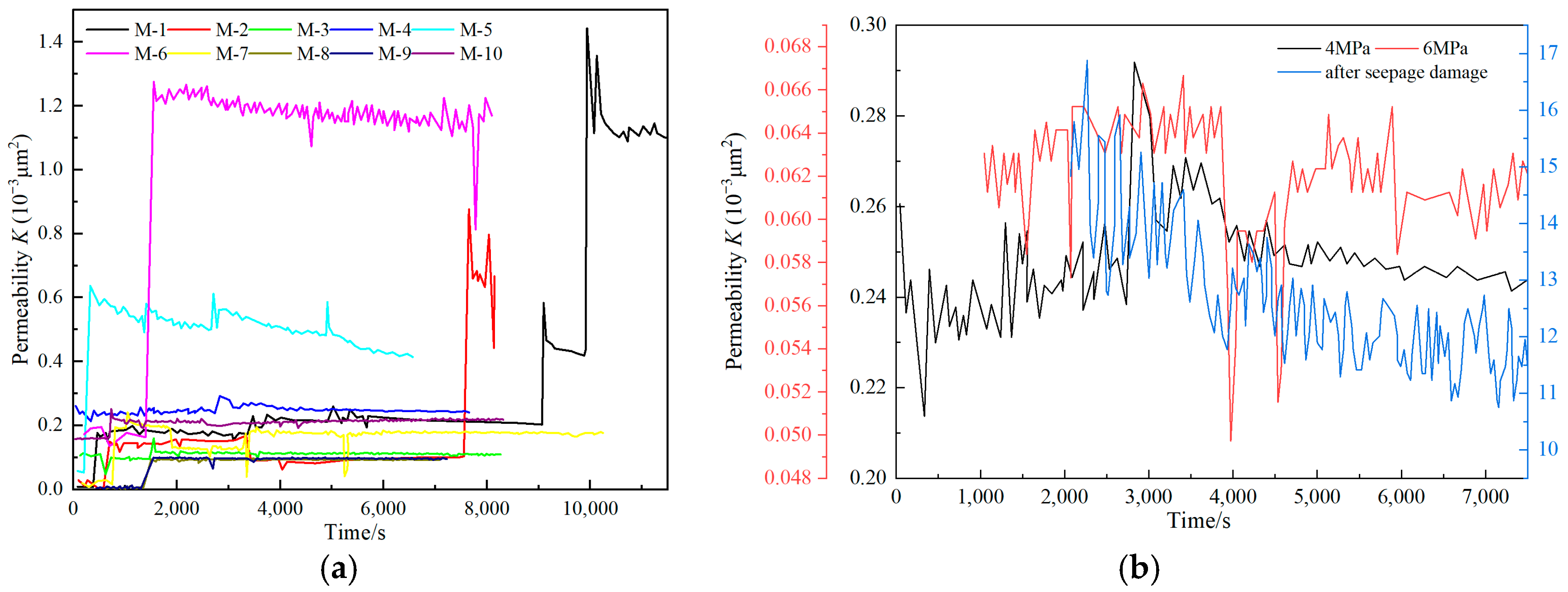
3.1. Test Results of Coal Samples

The experimental investigation into the permeability of coal samples revealed a range from 0.09 × 10⁻³ to 0.24 × 10⁻³ μm2, highlighting considerable variability in permeability, particularly during the saturated seepage stage for certain samples (as detailed in Table 3). This range of permeability values is crucial as it reflects the inherent heterogeneity of the coal samples, which can be attributed to differences in their microstructure, pore distribution, and the presence of natural fractures [17,18,19].
By analyzing the permeability change curves over time, we can discern several key characteristics of the seepage process across different coal samples:
  • Stable Stage and Mutation Stage:
Most coal samples underwent progression from a saturated seepage stage, characterized by relatively consistent fluid flow, to a stable seepage stage, where permeability remained constant or varied minimally. This behavior suggests that the internal pore structure and fractures of the coal samples reached a state of equilibrium under the prevailing experimental conditions. This is also similar to the stress “plateau period” or primary pore and pore density stages mentioned by some scholars when conducting coal sample soaking experiments [19,34], that is, the internal moisture of the coal sample has a certain buffering effect on the deformation of the coal sample, which will slow down the further expansion and damage of cracks or pores in a short period of time after the coal sample is saturated with water, which is what we call the stable stage.
However, certain samples exhibited abrupt changes or fluctuations in permeability before stabilizing, indicating a mutation stage. This stage is particularly important as it signifies a transitional phase where the internal structure of the coal is adjusting to external pressures or fluid flow, leading to sudden changes in permeability. Mainly due to the swelling of the matrix in coal rock by water, the original structure becomes more compact. With the continuous increase in soaking time, the cement is gradually diluted and internal structures are mutually squeezed and destroyed, resulting in increased porosity and ultimately leading to changes in permeability [34]. For example, in samples M-6 and M-9, significant permeability mutations were observed in response to changes in confining pressure (illustrated in Figure 4a). These mutations are likely caused by the dynamic behavior of fractures within the coal, which can either open or close suddenly due to the applied pressure, drastically altering the permeability.
2.
Effect of Confining Pressure:
During the experiments, the fracture structures of several coal samples underwent significant changes, which notably impacted their permeability characteristics. These structural changes primarily manifested in two forms: (1) coal chips and blockages within the seepage channels, and (2) fissure expansion due to mechanical and hydraulic influences.
One of the key phenomena observed was the presence of coal chips and the resulting blockages within the seepage channels of some coal samples. These blockages occurred as fragments of coal, dislodged during the experiments, entered the fluid pathways, obstructing the flow. Consequently, this led to noticeable fluctuations in permeability as the detached coal particles intermittently clogged the flow channels. In samples M-3 and M-5, for example, the permeability curves (Figure 4a) showed significant fluctuations during specific periods. These fluctuations were marked by sudden drops in permeability, followed by gradual recovery as the blockages cleared, either naturally or due to changes in pressure conditions, allowing the coal chips to move through the system. This dynamic interaction between the coal matrix and fluid flow indicates that the integrity of the seepage channels was periodically compromised by the presence of coal chips. The gradual permeability recovery suggests that the blockages were temporary, with the channels exhibiting partial self-restoration, although not to their original state. Additionally, the increase in coal chips observed in the seepage flow provides direct evidence of changes occurring within the fracture structures of the coal samples. As shown in Figure 5, these coal chips support the idea that the fracture network within the coal is not static but is continually modified during the experiments. The generation of coal chips suggests the degradation of the coal matrix, where mechanical stress and hydraulic forces cause fragments to break away and enter the fluid flow, altering the permeability dynamics [17,35].
In addition to coal chip blockages, another significant structural change observed was the expansion and increased connectivity of fissures, particularly under repeated pressurization and the subsequent restoration of confining pressure. This phenomenon was most prominent in sample M-4, where the combination of external forces and hydraulic pressure led to the substantial, progressive modification of the fracture network. In sample M-4, repeated cycles of increasing and restoring confining pressure induced a gradual extension of existing fractures and the formation of new fissures within the coal matrix. Furthermore, the effect of confining pressure on permeability was particularly evident, with higher confining pressures causing a significant reduction in permeability. For instance, sample M-4 exhibited stable permeability at a confining pressure of 4 MPa, but when the pressure was increased to 6 MPa, a marked decline in permeability was observed after 3000 s (Figure 4b). This suggests that under increased external forces, fractures within the coal gradually closed, narrowing the seepage channels and reducing fluid flow. The coal’s plastic deformation under stress compresses pore spaces and fractures, ultimately lowering permeability. This behavior highlights the sensitivity of coal’s permeability to external stress, with important implications for the extraction and management of resources such as coalbed methane [35,36,37].

3.2. Analysis of Permeability Variation Causes

The initial permeability of coal samples is closely related to their internal fracture structures. Coal samples with low initial permeability typically have fewer primary fractures and more intact structures, thus exhibiting better water-blocking ability [34]. During the seepage process, the hydraulic action on the fracture structure caused the detachment of coal chips, which blocked the seepage channels and led to fluctuations in permeability. This phenomenon is notably evident in the experimental results of M-6. And the detachment of coal fragments could obstruct flow channels and cause variability in permeability readings.
In addition, when confining pressure is increased and then restored, the permeability increases, indicating the formation of new fractures under disturbance, leading to enhanced permeability. This finding demonstrated that the application and subsequent reduction of confining pressure could cause pre-existing microfractures to propagate and connect, forming new pathways for fluid flow [34,36,37]. Thus, coal samples with high initial permeability have more primary and mining-induced fractures and poorer structural integrity, resulting in relatively lower water-blocking ability.
Under the combined action of external force and hydraulic pressure, the fractures in coal samples gradually extended and connected, forming macroscopic fractures and resulting in a significant increase in permeability. Therefore, increasing confining pressure causes the internal fractures of coal samples to gradually close, narrowing the seepage channels and thereby reducing permeability. This is particularly evident in the experimental results of M-4, where increased confining pressure led to a significant decrease in permeability due to fracture closure.

3.3. Implications of Fissure Seepage for Water Gushing-Out from Simulation Result

The pressure distribution within the fractures, as simulated and shown in Figure 6a, provides valuable insights into how water flows through these narrow and complex pathways. Pressure variations were examined by selecting eight key points along the fractures, comparing different fracture widths. The data from Table 4 demonstrate a clear trend: narrower fracture widths lead to greater pressure reduction. This finding emphasizes the critical role of fracture geometry in controlling fluid dynamics within fractured rock formations.
When comparing fractures 1-1, 1-2, and 1-3, significant differences in pressure reduction were observed due to varying fracture widths. For instance, water entering fracture 1-1, with an average pressure reduction intensity of 0.196 MPa, experienced a moderate pressure drop, which can be attributed to its relatively larger width. As the water progressed into fracture 1-2, the pressure reduction intensity increased sharply to 1.33 MPa due to the narrower width of the fracture, which constricted the flow path and increased resistance to water movement. In contrast, fracture 1-3 showed a pressure reduction intensity of 0.28 MPa, reflecting a lower reduction due to the already diminished inlet pressure as water moved through successive fractures.
Moreover, the data indicate a strong relationship between fracture width and pressure reduction. For fractures with widths greater than 0.11 mm, the pressure reduction intensity remains relatively low, typically ≤0.28 MPa. However, for fractures narrower than 0.11 mm, the intensity exceeds 0.4 MPa, illustrating the significant impact of microfracture dimensions on pressure dynamics. Fracture 1-1, with a width of 0.09 mm, exhibited a higher pressure reduction intensity than subsequent fractures with narrower widths, driven by the higher initial pressure at its entrance, amplifying the pressure drop as the water passed through this narrow space.
The water flow velocity distribution, shown in Figure 6b, further clarifies the impact of fracture width on fluid dynamics. In areas where the fractures narrowed, flow velocity increased dramatically, reaching localized peaks of up to 30 m/s. This acceleration occurred due to the constriction caused by narrower fractures. However, this effect was not uniform across the fracture network, with overall seepage velocity decreasing significantly as water exited the system. The outlet velocities often dropped to almost 0 m/s, highlighting how narrow microfractures effectively regulate and restrict fluid flow.
The relationship between fracture width and pressure reduction intensity, visualized in Figure 6c, reveals that when fracture widths are less than 0.11 mm, a pronounced reduction in water pressure occurs. This trend, represented by a fitted curve, identifies a critical threshold below which abrupt changes in fracture seepage behavior may be expected. These findings underline the importance of microfracture widths in dictating pressure and flow characteristics in fractured systems.
The results from the simulated pressure distribution and water flow velocity reveal key insights into the effects of fracture width on fluid dynamics in fractured coal formations. Narrower fractures were found to significantly increase both pressure reduction and flow velocity, with microfractures serving as critical bottlenecks that control overall fluid movement. Specifically, fractures narrower than 0.11 mm were associated with heightened pressure reduction, emphasizing their role in dictating fluid resistance and permeability.
The analysis demonstrates that fracture width plays a pivotal role in regulating pressure and flow behavior. Fractures below a critical width of 0.11 mm were particularly impactful, triggering sudden changes in seepage pressure. The narrowing of fractures not only increases local flow velocity but also causes substantial reductions in overall seepage velocity, resulting in nearly stagnant conditions at the fracture outlets.
Based on the analysis results of this study, fracture width, particularly the threshold of 0.11 mm, has become an important reference indicator for assessing the changes in the physical properties of coal pillars in the old mined-out areas due to water infiltration, which may further lead to water hazards. When there are numerous microfractures in coal with widths less than 0.11 mm, fluid entering smaller fractures from larger ones tends to accumulate significant water pressure at the entrance. Initially, this water pressure may provide some support to the small fractures. However, as the duration of water infiltration increases, these microfractures gradually expand and widen, potentially leading to the sudden release of accumulated water pressure, resulting in a significant increase in coal permeability. This abrupt change can easily trigger water hazards in old mined-out areas without any obvious warning signs.

4. Conclusions

In summary, the experimental and numerical analysis of coal sample permeability and fracture dynamics provided significant insights into the complex interplay between fracture width, confining pressure, and fluid flow. The results demonstrated that coal samples exhibit a range of permeability values, influenced by their inherent microstructural characteristics. The study identified distinct stages of permeability behavior, including stable and mutation phases, with abrupt changes often driven by alterations in confining pressure. These fluctuations were closely tied to the dynamic behavior of fractures within the coal, which responded to external forces by either expanding or contracting, thus affecting permeability. Narrower fractures were found to cause greater pressure drops and higher local flow velocities, leading to significant variability in fluid dynamics. The identification of a threshold width becomes more pronounced provides a valuable criterion for predicting sudden changes in fracture seepage behavior.
Therefore, testing the characteristics of microfractures in the coal pillars of old mined-out areas, especially identifying and determining the fracture threshold that may cause a sudden change in permeability, is crucial for prevention. Although coal properties differ significantly across various mining regions, and their response to changes in physical properties due to water infiltration also varies, this study indicates that microfracture size plays a key role in controlling pressure changes and fluid dynamics. Thus, while 0.11 mm is considered a critical threshold in this study, it is not universally applicable as a sole standard. The critical fracture width may vary in different mining regions, and adjustments and evaluations need to be made according to the specific characteristics of the coal. This study emphasizes the key role of microfracture size in controlling pressure dynamics, providing an important reference for assessing and preventing water hazards in coal pillars in old mined-out areas, while also underscoring the necessity for different regions to determine their own critical fracture thresholds.

Author Contributions

Conceptualization, B.L. and C.Z.; methodology, B.L.; software, B.L.; validation, B.L. and C.Z.; formal analysis, C.Z., P.Z. and J.H.; investigation, C.Z., P.Z. and J.H.; resources, B.L.; data curation, B.L.; writing—original draft preparation, B.L. and C.Z.; writing—review and editing, B.L. and C.Z.; visualization, P.Z. and J.H.; supervision, B.L.; funding acquisition, B.L. All authors have read and agreed to the published version of the manuscript.

Funding

This research was funded by the Basic Research Program of Shanxi Province, China, grant number 20210302124438.

Institutional Review Board Statement

Not applicable.

Informed Consent Statement

Not applicable.

Data Availability Statement

The raw data supporting the conclusions of this article will be made available by the authors on request.

Acknowledgments

We would like to thank the Xi Shan Coal Electricity Group Co. for their help and support in on-site sampling and technical exchanges. We thank the editors and reviewers for their time and effort, as well as for their suggestions and comments.

Conflicts of Interest

The authors declare no conflicts of interest.

References

  1. Meng, Z.; Li, G.; Xie, X. A Geological Assessment Method of Floor Water Inrush Risk and Its Application. Eng. Geol. 2012, 143–144, 51–60. [Google Scholar] [CrossRef]
  2. Dai, G.; Xue, X.; Xu, K.; Dong, L.; Niu, C. A GIS-Based Method of Risk Assessment on No.11 Coal-Floor Water Inrush from Ordovician Limestone in Hancheng Mining Area, China. Arab. J. Geosci. 2018, 11, 714. [Google Scholar] [CrossRef]
  3. Li, Y.M. Research on Stability of Overlying Strata and Reasonable Waterproof Coal Pillar with Backfilling Mining in Steep Seam under Water Body. Ph.D. Thesis, China University of Mining and Technology, Xuzhou, China, 2012. [Google Scholar]
  4. Luo, B. Reseach on the Mechanism of Water-conducted Fractures in Rock and Coal Near the Goafs. Ph.D. Thesis, China University of Mining and Technology, Xuzhou, China, 2021. [Google Scholar]
  5. Sun, Q. Analysis of seepage processes within coal rock bodies under pressure water sources. Saf. Coal Mines 2006, 2, 58–59. [Google Scholar]
  6. Li, S.; Fan, C.; Han, J.; Luo, M.; Yang, Z.; Bi, H. A Fully Coupled Thermal-Hydraulic-Mechanical Model with Two-Phase Flow for Coalbed Methane Extraction. J. Nat. Gas Sci. Eng. 2016, 33, 324–336. [Google Scholar] [CrossRef]
  7. Shu, Y.; Sang, S.; Zhou, X.; Zhao, F. A Coupled Hydraulic–Mechanical Model with Two-Phase Flow for Fracturing Development of Undersaturated Coalbed Methane Reservoirs Considering Permeability Velocity-Sensitive Damage. Nat. Resour. Res. 2023, 32, 2053–2076. [Google Scholar] [CrossRef]
  8. Huang, F.; Kang, Y.; You, L.; Li, X.; You, Z. Massive Fines Detachment Induced by Moving Gas-Water Interfaces during Early Stage Two-Phase Flow in Coalbed Methane Reservoirs. Fuel 2018, 222, 193–206. [Google Scholar] [CrossRef]
  9. Du, Z. Study on Theoretics of Hydraulicfracturing in Coal Bed and Its Applications. Ph.D. Thesis, China University of Mining and Technology, Xuzhou, China, 2008. [Google Scholar]
  10. Yao, Q.; Li, Y.; Li, X.; Yu, L.; Zheng, C. Permeation–Strain Characteristics and Damage Constitutive Model of Coal Samples under the Coupling Effect of Seepage and Creep. Int. J. Rock Mech. Min. Sci. 2024, 177, 105729. [Google Scholar] [CrossRef]
  11. Lin, F.; Huang, G.; Jiang, D.; He, Y.; Fan, J. Experimental Study on Coal Permeability and Damage Evolution Under the Seepage-Stress Coupling. Front. Earth Sci. 2022, 10, 847392. [Google Scholar] [CrossRef]
  12. Wen, G.; Yang, S.; Liu, Y.; Wu, W.; Sun, D.; Wang, K. Influence of Water Soaking on Swelling and Microcharacteristics of Coal. Energy Sci. Eng. 2020, 8, 50–60. [Google Scholar] [CrossRef]
  13. Huang, Z.; Zhao, X.; Gao, Y.; Shao, Z.; Zhang, Y.; Liu, X. The Influence of Water Immersion on the Physical and Chemical Structure of Coal. Combust. Sci. Technol. 2022, 194, 1136–1154. [Google Scholar] [CrossRef]
  14. Zhang, Y.; Qi, X.; Zou, J.; Rao, Y.; Chen, L.; Zhang, L.; Ji, Y.; Liang, Z. Effects of Water Immersion on the Pore Structure and Thermodynamic Properties of Coal Gangue. Fuel 2023, 346, 128273. [Google Scholar] [CrossRef]
  15. Lu, Y.; Ye, M.; Ge, Z.; Zhou, Z.; Gong, S.; Wang, Z.; Huang, S.; Guan, Y. Study on the Evolution Mechanism and Compression Effect of Coal Pores Subjected to Water Injection. Energy Fuels 2022, 36, 887–896. [Google Scholar] [CrossRef]
  16. Lu, Y.; Wang, L.; Ge, Z.; Zhou, Z.; Deng, K.; Zuo, S. Fracture and Pore Structure Dynamic Evolution of Coals during Hydraulic Fracturing. Fuel 2020, 259, 116272. [Google Scholar] [CrossRef]
  17. Perera, M.S.A.; Ranjith, P.G.; Peter, M. Effects of Saturation Medium and Pressure on Strength Parameters of Latrobe Valley Brown Coal: Carbon Dioxide, Water and Nitrogen Saturations. Energy 2011, 36, 6941–6947. [Google Scholar] [CrossRef]
  18. Zhou, G.; Wang, C.; Liu, R.; Li, S.; Zhang, Q.; Liu, Z.; Yang, W. Synthesis and Characterization of Water Injection Fracturing Fluid for Wetting and Softening Coal Seam. Int. J. Rock Mech. Min. Sci. 2022, 150, 105024. [Google Scholar] [CrossRef]
  19. Liu, Z.; Wang, G.; Li, J.; Li, H.; Zhao, H.; Shi, H.; Lan, J. Water-Immersion Softening Mechanism of Coal Rock Mass Based on Split Hopkinson Pressure Bar Experiment. Int. J. Coal Sci. Technol. 2022, 9, 61. [Google Scholar] [CrossRef]
  20. Lu, W. Experimental Study on the Influence of Water Accumulation in the Mined-out Space on the Stability of Water Proof Coal and Rock Pillar in Ximing Coalmine. Master’s Thesis, China University of Mining and Technology, Xuzhou, China, 2022. [Google Scholar]
  21. Liu, Q.; Xue, Y.; Ma, D.; Li, Q. Failure Characteristics of the Water-Resisting Coal Pillar under Stress-Seepage Coupling and Determination of Reasonable Coal Pillar Width. Water 2023, 15, 1002. [Google Scholar] [CrossRef]
  22. Chen, D.; Wang, X.; Bai, J.; Li, M. Characteristics of Waterproof Failure and Optimal Width of Narrow Coal Pillars under the Coupled Effects of Mining, Excavation and Seepage. Geomech. Geophys. Geo-Energy Geo-Resour. 2024, 10, 100. [Google Scholar] [CrossRef]
  23. Huang, P.; Zhang, Q.; Xie, J.; Li, J.; Zhang, Q.; Li, M.; Simao, F.C. Multiscale Study on Coal Pillar Strength and Rational Size under Variable Width Working Face. Front. Environ. Sci. 2024, 12, 1338642. [Google Scholar] [CrossRef]
  24. Fan, J.; Li, Z.; Feng, G.; Zhang, H.; Qi, C.; Zhang, J. Failure Analysis of Coal Pillars and Overburden from Underground Water Reservoir under the Mining-Water Invasion Coupling Effect. Eng. Fail. Anal. 2023, 151, 107406. [Google Scholar] [CrossRef]
  25. Jia, W.; Zhou, H.; Xie, S.; Wang, Y.; Hu, X.; Zhang, L. Pore-Pressure and Stress-Coupled Creep Behavior in Deep Coal: Insights from Real-Time NMR Analysis. Int. J. Min. Sci. Technol. 2024, 34, 77–90. [Google Scholar] [CrossRef]
  26. Guo, Z.; Vu, P.N.H.; Hussain, F. A Laboratory Study of the Effect of Creep and Fines Migration on Coal Permeability during Single-Phase Flow. Int. J. Coal Geol. 2018, 200, 61–76. [Google Scholar] [CrossRef]
  27. Fernandez, G.; Moon, J. Excavation-Induced Hydraulic Conductivity Reduction around a Tunnel—Part 1: Guideline for Estimate of Ground Water Inflow Rate. Tunn. Undergr. Space Technol. 2010, 25, 560–566. [Google Scholar] [CrossRef]
  28. Fernandez, G.; Moon, J. Excavation-Induced Hydraulic Conductivity Reduction around a Tunnel—Part 2: Verification of Proposed Method Using Numerical Modeling. Tunn. Undergr. Space Technol. 2010, 25, 567–574. [Google Scholar] [CrossRef]
  29. Rutqvist, J.; Noorishad, J.; Tsang, C.-F.; Stephansson, O. Determination of Fracture Storativity in Hard Rocks Using High-Pressure Injection Testing. Water Resour. Res. 1998, 34, 2551–2560. [Google Scholar] [CrossRef]
  30. Heiland, J. Laboratory Testing of Coupled Hydro-Mechanical Processes during Rock Deformation. Hydrogeol. J. 2003, 11, 122–141. [Google Scholar] [CrossRef]
  31. Chen, Y.-F.; Zhou, J.-Q.; Hu, S.-H.; Hu, R.; Zhou, C.-B. Evaluation of Forchheimer Equation Coefficients for Non-Darcy Flow in Deformable Rough-Walled Fractures. J. Hydrol. 2015, 529, 993–1006. [Google Scholar] [CrossRef]
  32. Nader, J.J. Darcy’s Law and the Differential Equation of Motion. Géotechnique 2009, 59, 551–552. [Google Scholar] [CrossRef]
  33. Simmons, C.T. Henry Darcy (1803–1858): Immortalised by His Scientific Legacy. Hydrogeol. J. 2008, 16, 1023–1038. [Google Scholar] [CrossRef]
  34. Xia, H.; Zhang, H.; Zhang, J. Research on Damage Mechanism and Mechanical Characteristics of Coal Rock under Water Immersion. Sustainability 2023, 15, 13095. [Google Scholar] [CrossRef]
  35. Liu, Y.; Zhao, D.; Li, Y.; Zhang, L. Permeability Evolution of Intact and Fractured Coal during Progressive Deformation Subjected to True Triaxial Stresses. Processes 2023, 11, 2826. [Google Scholar] [CrossRef]
  36. Cao, W.; Lei, Q.; Cai, W. Stress-Dependent Deformation and Permeability of a Fractured Coal Subject to Excavation-Related Loading Paths. Rock Mech. Rock Eng. 2021, 54, 4299–4320. [Google Scholar] [CrossRef]
  37. Wang, S.; Elsworth, D.; Liu, J. Permeability evolution in fractured coal: The roles of fracture geometry and water-content. Int. J. Coal Geol. 2011, 87, 13–25. [Google Scholar] [CrossRef]
Figure 1. Locations for coal rock samples.
Applsci 14 09210 g001
Figure 2. Fracture distribution of coal samples (a) and surface fracture network of coal sample (b).
Applsci 14 09210 g002
Figure 3. Schematic diagram of geometric model of fracture flow in coal sample.
Applsci 14 09210 g003
Figure 4. Curves of permeability over time (a) and influence of perimeter pressure on permeability (b).
Applsci 14 09210 g004
Figure 5. Coal sample after seepage failure (a), the residue of slack on the plug of gripper (b), and slack in water after seepage (c).
Applsci 14 09210 g005
Figure 6. Pressure distribution of fissure fluid (a), velocity distribution map in fissure (b), and relationship between fissure width and the value of pressure reduction (c).
Applsci 14 09210 g006
Table 1. Characteristic parameter table of coal sample to be measured.
Coal Sample NumberDiameter (mm)Length (mm)Mass (g)Volumetric Weight (N/m3)Fissure Development
M-124.7630.1017.2012.32 3 microfractures
M-224.8230.2219.2312.96 1 microfractures
M-324.8230.2419.1912.80 2 microfractures
M-424.7430.0016.8112.32 1 microfractures
M-524.8230.2017.8213.01 One X-shaped microfissure
M-624.7430.1220.2115.02 Multiple microfissures
M-724.8630.1019.9713.18 1 microfractures
M-824.7830.2017.2312.60 1 microfractures
M-924.7230.1219.3812.83 Multiple microfissures
M-1024.8830.2019.2613.01 Multiple microfissures
Table 2. Statistical table of seepage test pressure and injection flow.
Confining Pressure PC (MPa)Axial Compression PA (MPa)Water Injection Flow q (mL/min)
4.04.02.0
Table 3. Permeability of coal sample in saturated seepage stage.
SamplePermeability K (10−3 μm2)SamplePermeability K (10−3 μm2)
M-10.2M-61.2
M-20.15M-70.13
M-30.11M-80.09
M-40.24M-90.10
M-50.5M-100.22
Table 4. The strength of pressure reduction at different crack width positions.
Number1-11-21-31-42-12-22-32-4
Width of the fissure w (mm)0.200.090.160.140.100.180.110.09
The value of pressure reduction p′ (MPa)0.191.330.280.200.620.180.200.59
Disclaimer/Publisher’s Note: The statements, opinions and data contained in all publications are solely those of the individual author(s) and contributor(s) and not of MDPI and/or the editor(s). MDPI and/or the editor(s) disclaim responsibility for any injury to people or property resulting from any ideas, methods, instructions or products referred to in the content.

