Article

Study on the Influence of Casing Surface Morphology on the Plugging Performance of Downhole CO2 Plugging with Sn58Bi

College of Mechanical and Energy Engineering, Beijing University of Technology, Beijing 100124, China
*
Authors to whom correspondence should be addressed.
Appl. Sci. 2024, 14(20), 9249; https://doi.org/10.3390/app14209249
Submission received: 5 September 2024 / Revised: 27 September 2024 / Accepted: 29 September 2024 / Published: 11 October 2024

Abstract

:
Aimed at the problem of gas flurries in carbon dioxide (CO2) geologic sequestration in the wellbore, this paper proposes a sealing method in which the downhole casing is processed with threaded grooves and then plugged with a low-melting-point alloy plug. Based on this method, a small-scale experimental setup was developed for alloy plug molding and gas sealing in this study. Molding and gas sealing experiments with Sn58Bi alloy plugs inside casings with different surface morphologies were carried out. The gas leakage pathway was determined. The microstructure of the interface between the alloy plug and casing was analyzed using an optical microscope. The influence of the inner surface roughness, threaded groove, length-to-diameter ratio, and ambient temperature on the gas sealing performance of the alloy plugs was analyzed. The experimental results show that, with an increase in ambient temperature, the gas sealing performance of the casing increases significantly; when the inner surface of the casing is processed through threaded grooves, the gas sealing performance is better than with smooth hole casing; the gas sealing performance of the alloy plug presents an obvious linear positive correlation with their length-to-diameter ratio. This research provides theoretical support for downhole CO2 plugging using Sn58Bi in the casing.

1. Introduction

With the continued exploitation and large-scale application of fossil fuels such as coal, oil, and natural gas in countries all over the world, the content of greenhouse gases such as CO2 in the atmosphere has been rising, leading to global warming and the frequent occurrence of extreme weather. For this reason, countries around the world are paying more and more attention to how to effectively control greenhouse gas emissions and complete sustainable development [1]. In recent years, the international community has reached a unanimous consensus on CO2 emission reduction, and carbon capture, utilization, and storage (CCUS) is an important means of CO2 emission reduction [2]. Currently, the main methods of CO2 storage include geological storage, oceanic storage, chemical storage, etc. Among them, geological storage aims to inject CO2 into the Earth’s strata so that the CO2 is stored underground in a supercritical state, and this method can complete permanent storage of CO2 and improve the extraction efficiency of crude oil under certain conditions [3]. Ideal CO2 sequestration sites are often located in concentrated oil and gas development blocks, where abandoned wellbores are common, and the risk of CO2 leakage along the abandoned wellbores increases dramatically when the abandoned wellbores penetrate the cap layer. Great plugging performance is the key to complete downhole carbon-sequestration technology; therefore, how to complete great long-term plugging of wellbores is important to CCUS [4].
Currently, cement is the main plugging material used in CO2 geological storage operations, but in most cases, there are leakage channels at the cement plug–casing interface that make it difficult to complete long-term CO2 plugging [3,5]. The main reasons for the generation of leakage channels include (1) cement shrinkage during solidification caused by hydration or phase changes, which destroy the integrity of the wellbore [6]; (2) the acidity of CO2 gas, which can seriously damage the cement plug by hydration of the silicate cement system [7] and cause serious breakage of the seal at the cement plug–casing interface; (3) the cement’s low tensile strength after solidification, which makes it prone to fractures and other defects in the high-pressure environment downhole, reducing the plugging effect.
In order to solve the problem of gas flurries caused by these cementitious materials, Carragher [8] proposed the adoption of low-melting-point alloys to complete downhole plugging. In 2018, Bi-Sn UK [9] proved the feasibility of alloy plugging in 12 wells in Oklahoma and 2 wells in Alaska. Thorstensen [10] used a total of 35 bismuth alloy plugs to seal 30 wells abandoned offshore of Norway and showed experimentally that the seals should last at least 1000 years. In the same year, Zhang [11] conducted experimental tests on the sealing effect of alloy plugs in brine wells and confirmed the feasibility of alloy plugs for brine well plugging. In 2023, Lewaa [12] experimentally verified that alloy plugs have great mechanical pressure-bearing properties and can withstand large axial loads. The alloy plug mainly relies on volume expansion in the solidification process to generate a certain radial force, which brings the inner wall of the casing and the alloy body into close contact to complete the plugging, and its sealing path is the inner wall of the casing and the alloy contact position of the circular surface. However, the alloy plugging smooth hole casing method needs to position a plug with a longer sealing length downhole; therefore, this paper proposes a sealing method in which the downhole casing is processed with threaded grooves and then plugged with a low-melting-point alloy plug. The sealing path of the alloy plug is changed from a round surface to a threaded surface, and the sealing path of the alloy plug’s unit length is increased so that the casing can be completed for long-term sealing by an alloy plug with a shorter sealing length.
In order to verify the feasibility of the method and research the influence of each parameter, in this paper, a small-scale experimental setup was developed for alloy plug molding and gas sealing. The researchers carried out molding and gas sealing experiments with Sn58Bi alloy plugs inside casings of different surface morphologies, analyzed the sealing performance of the alloy plug, determined the gas leakage pathway, and analyzed the microscopic structure of the alloy plug–casing interface using an optical microscope; the effects of the inner surface roughness of the casing and threaded grooves on the gas sealing performance of the alloy plug were analyzed, and the effects of alloy plug sealing length and ambient temperature on the sealing performance of the alloy plug were researched. The research in this study could provide theoretical support for the application of the downhole CO2 plugging method using Sn58Bi in casings.

2. Materials and Methods

2.1. Sn58Bi Alloy Plugging Casing Method

In this study, the low-melting-point alloy used is Sn58Bi alloy, which is a eutectic alloy consisting of 58% Bi and 42% Sn. The properties of this alloy are shown in Table 1.
Sn58Bi alloy has the following advantages [15,16]:
  • Low melting point: Its melting process requires low energy that does not affect the strength of the casing body;
  • Micro-expansion: This alloy expands in volume (similar to water freezing) when it solidifies from the liquid state to the solid state;
  • Corrosion resistance: The alloy is able to resist corrosion, especially H2S and CO2;
  • High density: Due to the high density of the alloy, other impurities in the wellbore float to the top during the melting and solidification process, assisting in forming a pure alloy plug for seal integrity;
  • High mobility in liquid-state alloys is capable of completing seals in tiny gaps and irregular shapes.
This kind of alloy can be formed into a series of alloys with melting points of 138 °C–263 °C based on different alloy ratios [17], which makes it easy to optimize the selection based on the formation temperature.
There is no wettability between the Sn58Bi alloy and the metal casing [15], and the sealing of the alloy plug is completed by the expansion of the alloy, which is caused by its conversion from a liquid to a solid within the downhole casing, as shown in Figure 1.
The alloy plugging smooth hole casing method proposed by Carragher [8] mainly relies on the radial force generated after the alloy solidifies and expands, as shown in Figure 1a, which makes the alloy plug come into close contact with the casing and thus completes the plugging, and the sealing path is the round surface of the inner wall of the casing in contact with the alloy. This paper proposes a sealing method wherein the downhole casing is processed with threaded grooves and then plugged by low-melting-point alloy plug. As shown in Figure 1b, the length of alloy plug in the threaded casing (the inner surface of the casing was turned threads) is similar to the length of alloy plug in the conventional alloy plugging casing method with the same amount of alloy. When the sealing surface changes from a round surface to a threaded surface, the sealing path increases, which might increase the gas sealing performance of the alloy plug.
Compared with cement plugging casing method, the advantages of alloy plugging threaded casing method are as follows:
  • High stability of sealing: Sn58Bi alloy itself has the characteristics of denseness, corrosion resistance, high strength, etc., and the alloy plug formed is able to withstand the interference of most unfavorable factors downhole;
  • Compared with the curing time during the molding process of cement plugs, the alloy plug can complete the sealing function after cooling naturally at the bottom of the well, and the operation time is greatly reduced;
  • After turning threads in the casing, the sealing path per unit sealing length is increased and gas sealing performance is improved, while the threaded structure increases the axial pressure-bearing capacity of the alloy plug.

2.2. Casing Material

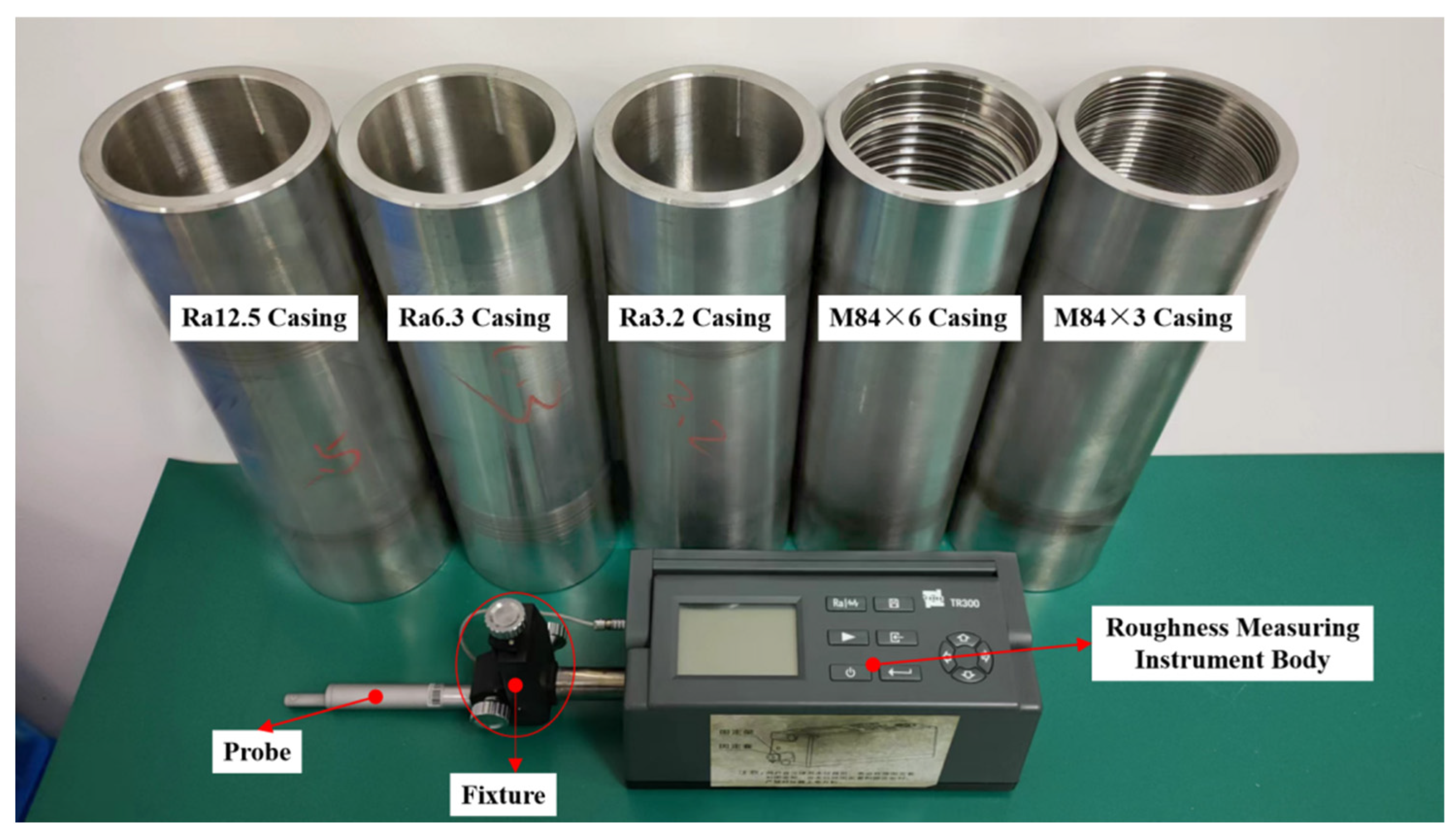
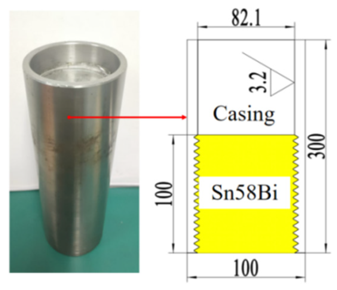
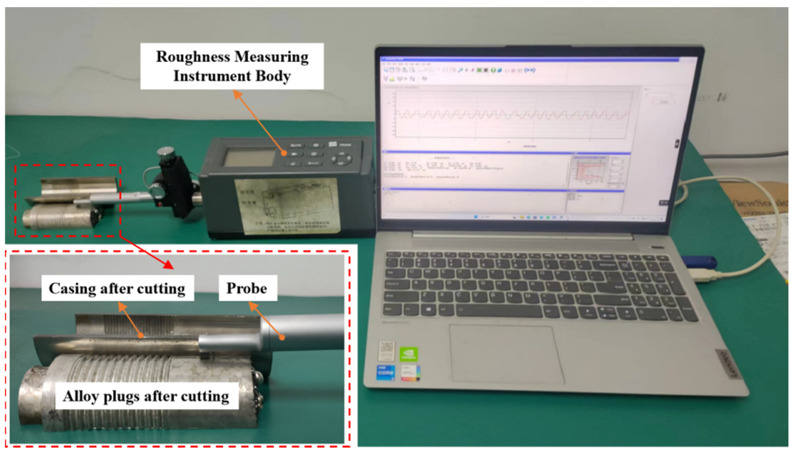
The casing used in the experiment was made of N80, which is a common casing material. The alloy plugs to be tested in the experiment were formed by Sn58Bi alloy in different types of casing. The casing has an outer diameter of 100 mm and an inner diameter of 82.1 mm, as shown in Figure 2. There were three types of casing with different inner roughness used in the experiments, categorized as smooth, medium-roughness, and high-roughness casings; the inner surface of the two smooth casings was processed with threaded grooves of different pitches; and the specific parameters of the casing used in the experiments are shown in Table 2.
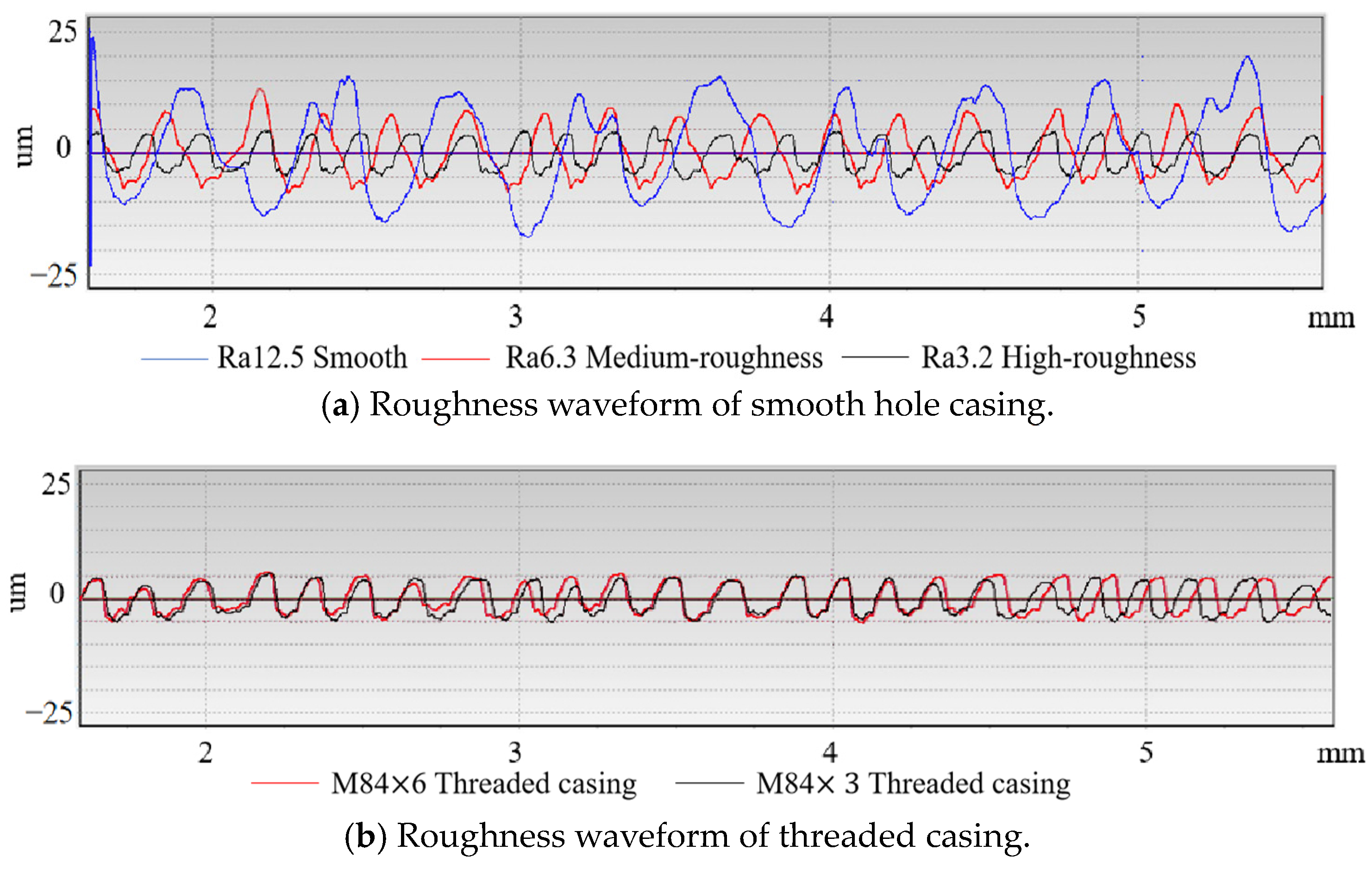
The movable surface roughness measuring instrument was used (shown in Figure 2) to measure the surface roughness of the casing. The surface roughness of the casing was visualized. The range of the instrument is 50 μm, and the stroke length is 5.6 mm. The measurements were conducted on the casing’s inner surface, and the results are shown in Figure 3, which shows that the roughness distribution of each casing is relatively uniform and there is no obvious process defects problems interfering with the experimental results.

2.3. Alloy Plug Sample Molding Setup

In order to study the gas sealing performance of Sn58Bi alloy plug, a small-scale experimental setup was constructed for alloy plug molding in this paper, as shown in Figure 4, which adopted the heating method of externally heating the metal casing with a heating ring to melt the alloy inside the casing.
The steps of the alloy plug molding experiment are as follows:
  • Install a high-temperature-resistant rubber plug at the bottom of the casing to prevent the molten state alloy from leaking out from under the casing;
  • Calculate the weight of alloy required for the corresponding length of alloy plug and place the weight of alloy in the alloy casing;
  • Place the casing with alloy fragments in the heating unit;
  • Turn on the temperature control box, set the heating temperature at 250 °C, and heat for 2 h to ensure that the alloy is fully molten;
  • Close the heating setup. The alloy plug is allowed to stand for 6 h so that the alloy plug cools to room temperature;
  • Remove the casing with the alloy plug sample and pull out the rubber plug.
The partially formed alloy plugs are shown in Figure 5.

2.4. Gas Sealing Performance Test Setup

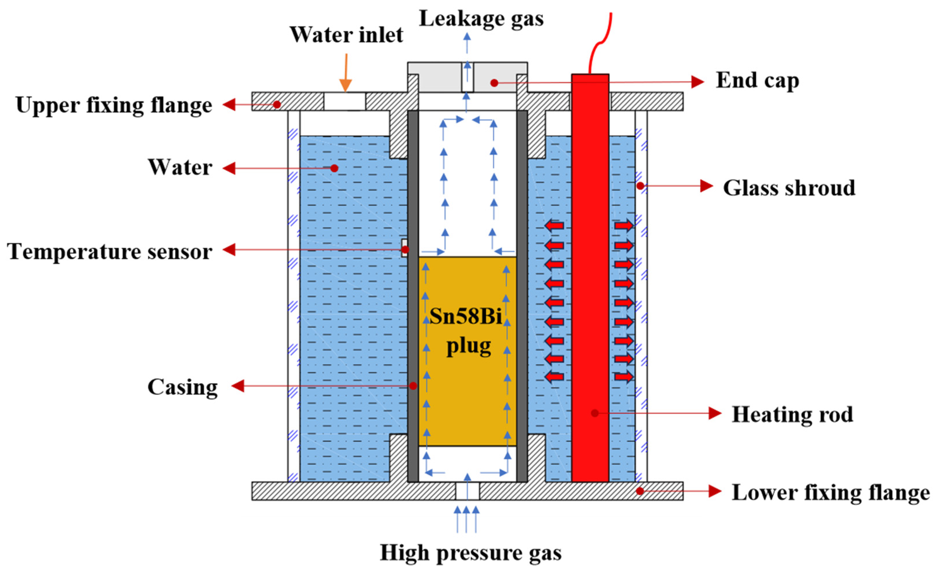
Gas sealing performance is one of the important indexes used for evaluating the sealing effect of downhole alloy plug, and better gas sealing performance can prevent the residual gas at the bottom of the well from breaking through the alloy plug and polluting the surface environment. In order to study the gas sealing performance of Sn58Bi alloy plug, a small-scale experimental setup was constructed for gas sealing performance test in this study, as shown in Figure 6. The experimental setup mainly consists of high-pressure air pump, alloy plug samples, and support parts.
The air pump used in the experiment can provide air pressure up to 40 MPa. In order to simulate the actual downhole environment, the high-pressure gas enters the container through the air inlet at the bottom of the test setup, and the air outlet in the upper part of the setup is connected to the air pressure sensor. If the gas breaks through the alloy plug–casing interface, the air pressure above the alloy plug in the casing will increase, and the sensor’s reading will change; the sealing between the casing and the setup is completed by the high-temperature-resistant sealing ring, which ensures that the gas will not leak out from the connection between the casing and the setup during the experiment and interfere with the experiment.
The entire setup is divided into the casing area and heating area; the area between the casing and the glass shroud is the heating area, as shown in Figure 7. The heating method adopts heating rod with a constant temperature heating function for water bath heating. There are two holes turned on the upper fixing flange, one for water intake and the other for placing the heating rod containing a thermostat. The heating rods are connected to the power supply and the thermostat to change the ambient temperature during the test of the gas sealing performance of the alloy plug.

3. Experiments and Processes

3.1. Gas Sealing Performance Test

After ensuring that all the experimental setups were ready, the air pump was first opened for a short period of time for ventilation. Observations could be made through the casing and flange connection to check for the presence of bubbles in the water, testing whether there was any leakage in the setup.
After the sealing performance test of setup was completed, the casing with alloy plug sample was placed in the setup. The heating rod was activated to raise the water temperature to the required temperature, insulation was carried out, and the insulation time was set to 2 h to allow heat transfer from the casing to the alloy plug. Then, the gas sealing was completed test. Expanding air inside the casing during heating process might interfere with the experiment. Therefore, the air pressure sensor was installed at the end cap on the top of the setup after 1 h of heat preservation.
The air pump was opened to increase the air pressure under the alloy plug, which produced a differential pressure across the alloy plug. The differential pressure was gradually increased until the reading of air pressure sensor changed. Pressurizing was then stopped, and monitoring was continued for 2 h, until the pressure readings were stable. The difference of indication between the sensor and the air pump at this moment was recorded as the air pressure difference when the alloy plug failed. Under each condition, a group of alloy plug samples was tested at least three times to exclude the interference of accidental factors in the experimental process.

3.2. Analysis of Gas Leakage Sources and Surface Microstructure

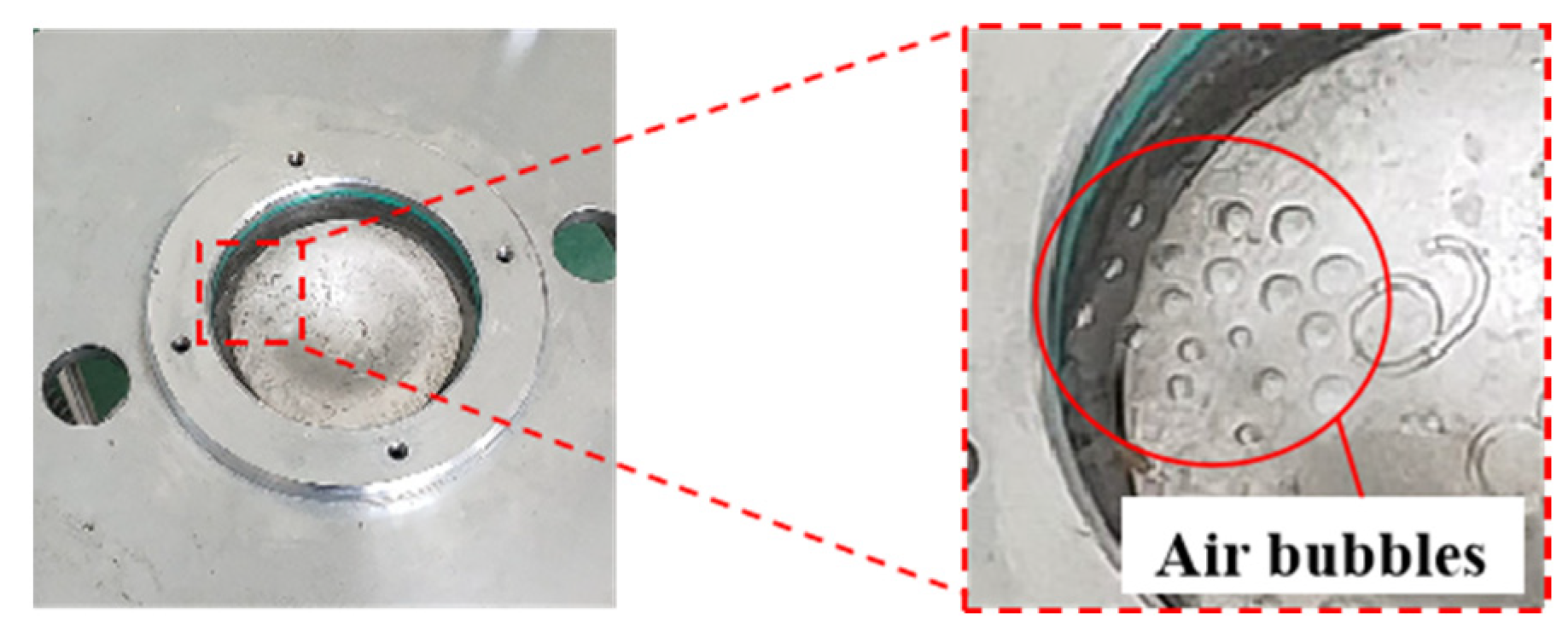
After completing the gas sealing performance test, the end cap at the top of the setup was opened, and an appropriate amount of water was added above the alloy in the experimental sample, as shown in Figure 8. At the bottom side of the plug, pressurization was carried out until bubbles were generated on the water surface. It could be clearly observed that the bubbles all came from the circumference of the alloy plug, which indicated that there was a micro-annular gap at the interface between the alloy and the casing, which formed a flow path for the passage of the gas. The absence of bubbles on the round surface of the alloy plug indicates that the experimental alloy plug did not generate a continuous path for fluid passage internally during the molding process.
The alloy plug samples were wire-cut, scanned, and analyzed using an optical microscope at several sampling points of the alloy plug samples, and the results are shown in Figure 9a. The 100 mm alloy plug had parts with a large gap, which was due to the fact that the upper part of the alloy plug fails to fill the surface of the threaded groove fully during the process of the alloy solidifying and expanding, while the lower part of the alloy plug fills the surface of the threaded groove fully due to the influence of the gravity of the alloy plug itself. As a result, the gap between the lower alloy plug and the casing was small and uniform. As shown in Figure 9b, there was a small and uniform gap between the alloy plug and the casing in the 150 mm alloy plug. This was due to the pressure generated by the alloy 50 mm above the threaded area, so the lower part of the alloy would fill the surface of the threaded groove fully during solidification and expansion, which was in contrast to the larger gap in the 100 mm alloy plug, indicating that the weight of the alloy itself could affect the molding process of the alloy plug.
The alloy plug was separated from the casing in the cut alloy plug sample, as shown in Figure 10. And the surface of the alloy plug and casing was measured for roughness. The results of the measurements are shown in Figure 11.
The leakage pathway in the casing–alloy interface is also due to the poor engagement of microstructures on the contact surfaces, which results in micro-annular channels. Figure 11b indicates the poor surface engagement area, where the surface roughness of the alloy plug was low and the surface roughness of the casing at the corresponding position was high. Therefore, more gaps between the surfaces of the alloy plug and casing at this location were generated, which was the main concentration area of the micro-annular gap. Meanwhile, Figure 11c is the better surface engagement area, where the peaks and valleys on the micro-surface of the alloy plug and the corresponding micro-surface of casing formed a better engagement, and the number of micro-annular gaps generated in this area was relatively small.

4. Experimental Results

By testing the gas sealing performance of each casing sample under different conditions, the gas breakthrough pressure values for gas sealing performance failure under different conditions of each casing sample were obtained, and all the experimental results were summarized and plotted.

4.1. Influence of Ambient Temperature and Threaded Groove on the Gas Sealing Performance of Alloy Plug

4.1.1. The Influence of Ambient Temperature on Gas Sealing Performance

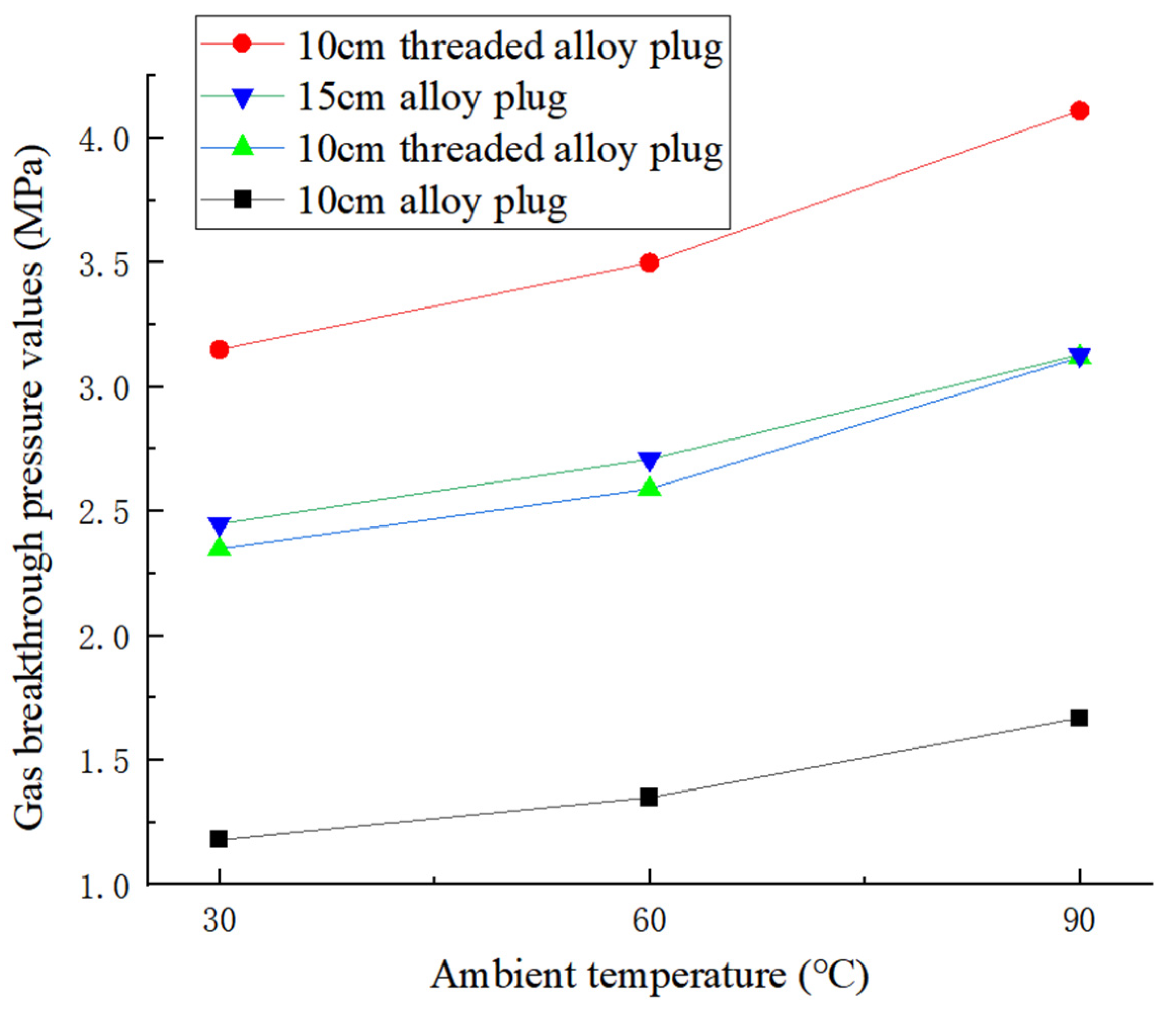
When the ambient temperature at which the samples in the experiment were located was raised from 30 °C to 60 °C, respectively, the gas breakthrough pressure values at the time of gas sealing performance failure of all alloy plug samples increased by about 10% on average, and when the ambient temperature was raised from 60 °C to 90 °C, the gas breakthrough pressure values increased by about 15% on average, as shown in Figure 12. This indicates that as the temperature increases, the expansion of the alloy plug is greater than the casing bore, and the alloy plug generates greater radial force, which in turn increases the gas sealing performance of the alloy plug. This trend is more pronounced when the temperature exceeds 60 °C.

4.1.2. The Influence of Threaded Groove on Gas Sealing Performance

Comparing the smooth hole casing samples, the gas sealing performance of the alloy plug sample with M84 × 6 threaded grooves on the inner surface increased by 1.18 MPa on average, while the gas sealing performance of the smooth casing sample with M84 × 3 threaded grooves on the inner surface increased by 1.89 MPa on average, as shown in Figure 12.
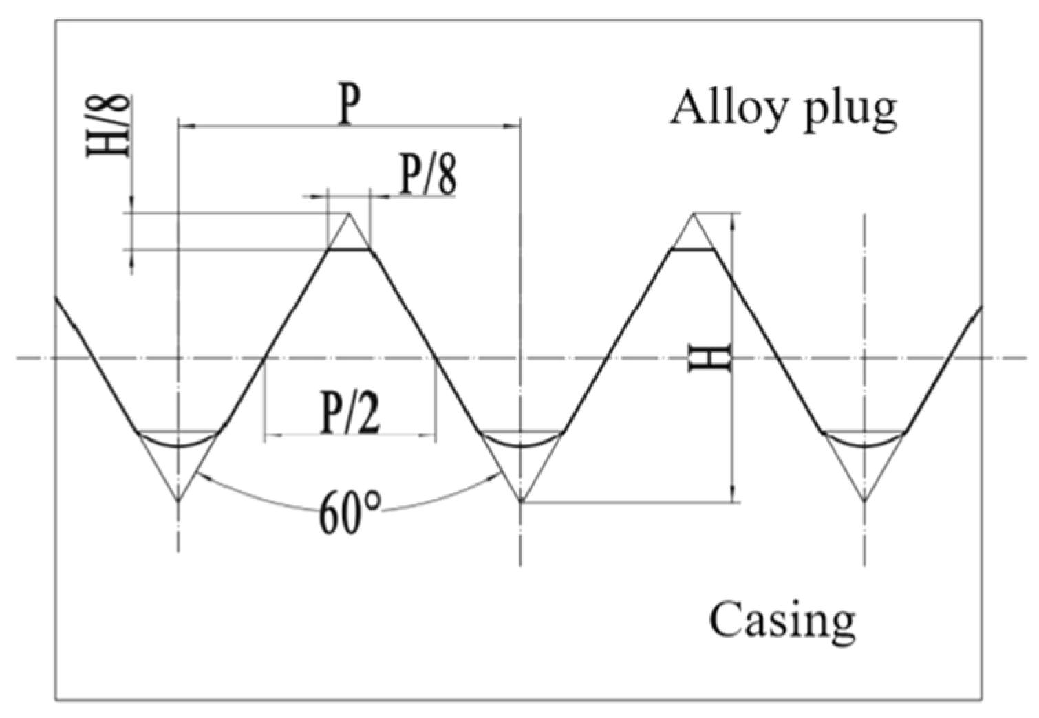
The flow path was formed by the contact between the alloy and the casing. And the flow path theoretically increased when the inner surface of the smooth hole casing was processed through threaded grooves, as shown in Figure 13. Assuming that the total length of the path on the axial surface of the alloy casing is   L M , the relationship between the total length of the path and the length of the thread is as follows due to the regularity of the thread itself [18]:
L M = L 0 P L p
In Equation (1), L 0 is the length of the threaded area, mm; P is the pitch, mm; and L p is the path length of the single thread, mm.
Since the threaded groove turned on the inner surface of the casing is a normal threaded groove, the following formula for calculating the single threaded path length can be deduced from the design criteria for normal threads [18]:
L p = P 8 + 1 1 4 1 8 P · s e c θ 2 + 180 ° θ 360 ° · 2 π · P 8 s i n θ
In Equation (2), θ is the normal pitch angle, θ = 60 ° .
The above formula   L M 1.526   L 0 can be simplified to obtain the path length of a standard ordinary thread. From this formula, it can be concluded that for the ordinary threaded casing designed according to the same standard, its path length will not change because of the change of pitch, and its path length is only related to the thread length.
In summary, after the 100 mm threaded groove is turned on the inner surface of the casing, it can be seen that the effective plugging length of the alloy plug increases by 52.6 mm relative to the actual plugging length. So, the gas sealing performance of the 100 mm threaded casing alloy plug sample should be close to that of the 150 mm smooth hole casing alloy plug. The increase in the gas sealing performance of the alloy plug with a large pitch is close to its theoretical value. But the increase in the gas sealing performance of the alloy plug with a small pitch exceeds its theoretical value. This indicates that the decrease in pitch can also improve the gas sealing performance of the alloy plug.

4.1.3. The Influence of Length-to-Diameter Ratio and Roughness on Gas Sealing

Performance of Alloy Plug

The gas sealing performance of alloy plugs in smooth casings, medium-roughness casing, and high-roughness casing of the same plugging length under the same test conditions did not show a significant difference, as shown in Figure 14.
In order to research the effect of the length-to-diameter ratio on the gas sealing performance of the alloy plug, gas sealing tests on different length-to-diameter ratios of alloy plugs at the same ambient temperature were conducted. The results are shown in Figure 14. The results show that the gas sealing performance of the alloy plugs in the smooth hole casing shows an obvious linear growth relationship with the increase in the plugging length. And the gas sealing performance of alloy plugs in threaded casing increases with the increase in the length-to-diameter ratio, and the growth trend is consistent.

5. Conclusions

This paper proposes a sealing method wherein the downhole casing is processed with threaded grooves and then plugged by a low-melting-point alloy plug. In this paper, the effect of surface roughness and threaded groove inside the casing on the gas sealing performance of alloy plugs was analyzed through experiments. And the effect of ambient temperature and length-to-diameter ratio on the gas sealing performance of alloy plugs was researched, which provided theoretical support for the application of the method of CCUS using Sn58Bi inside the casing. We obtained the following conclusions:
(1)
The sealing performance of the alloy plug is relatively affected by the ambient temperature. With the increase in ambient temperature, the radial stress inside the alloy plug–casing interface rises, the alloy combines more tightly with the inner surface of the casing, and the gas sealing performance of the alloy plug appears to be significantly increased.
(2)
The threaded groove on the inner surface of the casing has a significant effect on the gas sealing performance of the alloy plug. Under the condition of the same length-to-diameter ratio of the alloy plugs, the alloy plugs of the threaded casing have a significant increase in gas sealing performance due to the increase in the area of the alloy–casing interface. As the pitch decreases, the degree of gas flow path zigzagging increases, and the gas sealing performance of the alloy plug increases.
(3)
The gas sealing performance of alloy plugs showed an obvious linear positive correlation with their length-to-diameter ratio. The gas sealing performance of alloy plugs is less affected by the roughness of the inner surface of the casing. Relying only on the radial force generated by the micro-expansion during the molding process of the alloy plug, the alloy is not sufficient to fully fill the micron-sized grooves.
(4)
When the casing was processed through internal threaded grooves, the threaded grooves should be designed at the lower section position of the target area. The gravity force generated by the alloy above the threaded grooves can further increase the degree of filling of the molten alloy with the threaded portion, and this design method can further improve the gas sealing performance of the threaded alloy plug.

Author Contributions

C.Z.: Conceptualization, Data Curation, Formal Analysis, Investigation, Methodology, Formal Analysis, Project Administration. T.C.: Visualization, Writing—Original Draft, Writing—Review and Editing, Data Curation. W.W.: Resources, Software, Supervision, Writing—Review and Editing. G.L.: Project Administration, Validation, Funding Acquisition. All authors have read and agreed to the published version of the manuscript.

Funding

This research was funded by the Natural Science Foundation of China, contract No. U23B2081.

Institutional Review Board Statement

Not applicable.

Informed Consent Statement

Not applicable.

Data Availability Statement

The original contributions presented in the study are included in the article, further inquiries can be directed to the corresponding authors.

Acknowledgments

The authors would like to thank the Beijing University of Technology and the Natural Science Foundation of China for their support.

Conflicts of Interest

The authors declare no conflicts of interest.

Nomenclature

σ z Axial stress at the end of the plug (MPa).
θ The normal pitch angle.
P The pitch (mm).
L p The path length of the single thread (mm).
L 0 The length of the threaded area (mm).
L M The total length of the path on the axial surface of the alloy casing (mm).
ccusCarbon Capture, Utilization, and Storage.

References

  1. Li, H.F.; Wang, Q. Study on utilization and geological storage of CO2 in CCUS. Mod. Chem. Ind. 2022, 42, 86–90+95. [Google Scholar] [CrossRef]
  2. Liu, F.; Sheng, Z.; Li, J.; Yan, S.; Zhu, R. Estimation of Carbon Dioxide Storage Capacity of Depleted Gas Reservoirs in X Sag. Offshore Oil 2023, 43, 13–17. [Google Scholar] [CrossRef]
  3. Liu, Z.; Gao, M.; Zhang, X.; Liang, Y.; Guo, Y.; Liu, W.; Bao, J. CCUS and CO2 injection field application in abroad and China: Status and progress. Geoenergy Sci. Eng. 2023, 229, 212011. [Google Scholar] [CrossRef]
  4. Wang, D.; Li, J.; Liu, P.; Liu, X.; Lu, W.; Lian, Z. Simulation study of sealing integrity in abandoned wells within CO2 sequestration block. Drill. Fluid Complet. Fluid 2023, 40, 384–390. [Google Scholar] [CrossRef]
  5. Saasen, A.; Wold, S.; Ribesen, B.T.; Tran, T.N.; Huse, A.; Rygg, V.; Grannes, I.; Svindland, A. Permanent abandonment of a North sea well using unconsolidated well plugging material. SPE Drill. Complet. 2011, 26, 371–375. [Google Scholar] [CrossRef]
  6. Reddy, B.R.; Xu, Y.; Ravi, K.; Gray, D.; Pattillo, P.D. Cement-Shrinkage Measurement in Oilwell Cementing—A Comparative Study of Laboratory Methods and Procedures. SPE Drill. Complet. 2009, 24, 104–114. [Google Scholar] [CrossRef]
  7. Gong, P.; Fu, H.; He, D.; Wu, Y.; Mei, K.; Zhang, C.; He, X.; Liu, T.; Li, S.; Cheng, X. Novel material to enhance the integrity of CCUS cement sheath: Exploration and application of calcium aluminate cement. Gas Sci. Eng. 2024, 124, 205247. [Google Scholar] [CrossRef]
  8. Carragher, P.; Fulks, J. A New Look at Sealing with Bismuth and Thermite. In Proceedings of the SPE Annual Technical Conference and Exhibition, Dallas, TX, USA, 24–26 September 2018. [Google Scholar] [CrossRef]
  9. Carragher, P.; Fulks, J. Rigless Abandonment with Bismuth and Thermite. In Proceedings of the SPE Symposium: Decommissioning and Abandonment, Kuala Lumpur, Malaysia, 3–4 December 2018. [Google Scholar] [CrossRef]
  10. Thorstensen, E.; Vadset, K.; Straume, M.K.; Delabroy, L.; Abdelal, G.; Carragher, P.; Fulks, J.; Mason, D.L. Bismuth Plugs Used to Cap All Wells During the Final Phase of the Valhall DP Abandonment Campaign, Offshore Norway. In Proceedings of the OTC Offshore Technology Conference, Houston, TX, USA, 2–5 May 2022. [Google Scholar] [CrossRef]
  11. Zhang, H.; Ramakrishnan, T.S.; Elias, Q.K.; Perez, A., Jr. Evaluation of Bismuth-Tin Alloy for Well Plug and Abandonment. SPE Prod. Oper. 2020, 35, 111–124. [Google Scholar] [CrossRef]
  12. Lewaa, H.; Elahifar, B.; Sangesland, S. The sealing behavior of bismuth-based metal plugs. In Proceedings of the ASME 2023 42nd International Conference on Ocean, Offshore and Arctic Engineering OMAE2023, Melbourne, Australia, 11–16 June 2023. [Google Scholar] [CrossRef]
  13. Liang, B.; Hu, P.; Nie, Y.; Feng, G.; Zhou, J.; Bai, Y.; Niu, G.; Niu, W.; Zhou, Y. Experimental Study on the Influence of Temperature and Loading Rate on the Mechanical Properties of Sn-58Bi Alloy. Funct. Mater. 2021, 52, 1145–1155. [Google Scholar] [CrossRef]
  14. Zhang, H.; Ramakrishnan, T.S.; Elkady, Y.M.; Feng, Y.; Elias, Q.K. Comparative Evaluation of Bismuth-Silver and Bismuth-Tin Alloys for Plug and Abandonment. SPE Drill. Complet. 2021, 36, 368–382. [Google Scholar] [CrossRef]
  15. Abdelal, G.F.; Robotham, A.; Carragher, P. Numerical simulation of a patent technology for sealing of deep-sea oil wells using nonlinear finite element method. J. Pet. Sci. Eng. 2015, 133, 192–200. [Google Scholar] [CrossRef]
  16. Schuppert, A.; Polotzek, K.; Schmitt, J.; Busse, R.; Karschau, J.; Karagiannidis, C. A Full Laboratory Study on the Physical and Mechanical Properties of a Bismuth Plug. In Proceedings of the IADC/SPE International Drilling Conference and Exhibition, Stavanger, Norway, 7–9 March 2023. [Google Scholar] [CrossRef]
  17. Chen, X. Study on the Microstructure and Performance of Sn-Bi Based Solder. Ph.D. Thesis, Southeast University, Nanjing, China, 2017. Available online: https://kns.cnki.net/kcms2/article/abstract?v=KqXyGY4RJv0myydx0WA2mZoh-9SKB4apI9tsFEcdzMl0Vt4MBMbTyfo_yrtZfV-5x2xDewj7341fpY2PG-ZZpPu4Dq8n8YqoB0fYmsPPPTOpGMdflX9w0YHpxBHTiEw0bKhWpZ0leylQc5eiZSQfoKtAa-QE5hXcXNgzQFTX9n40IcYlfNRmwJrbJ3CSZFxD&uniplatform=NZKPT&language=CHS (accessed on 28 September 2024).
  18. Li, X.B. Threads and Their Couplings; China Planning Press: Beijing, China, 2004. [Google Scholar]
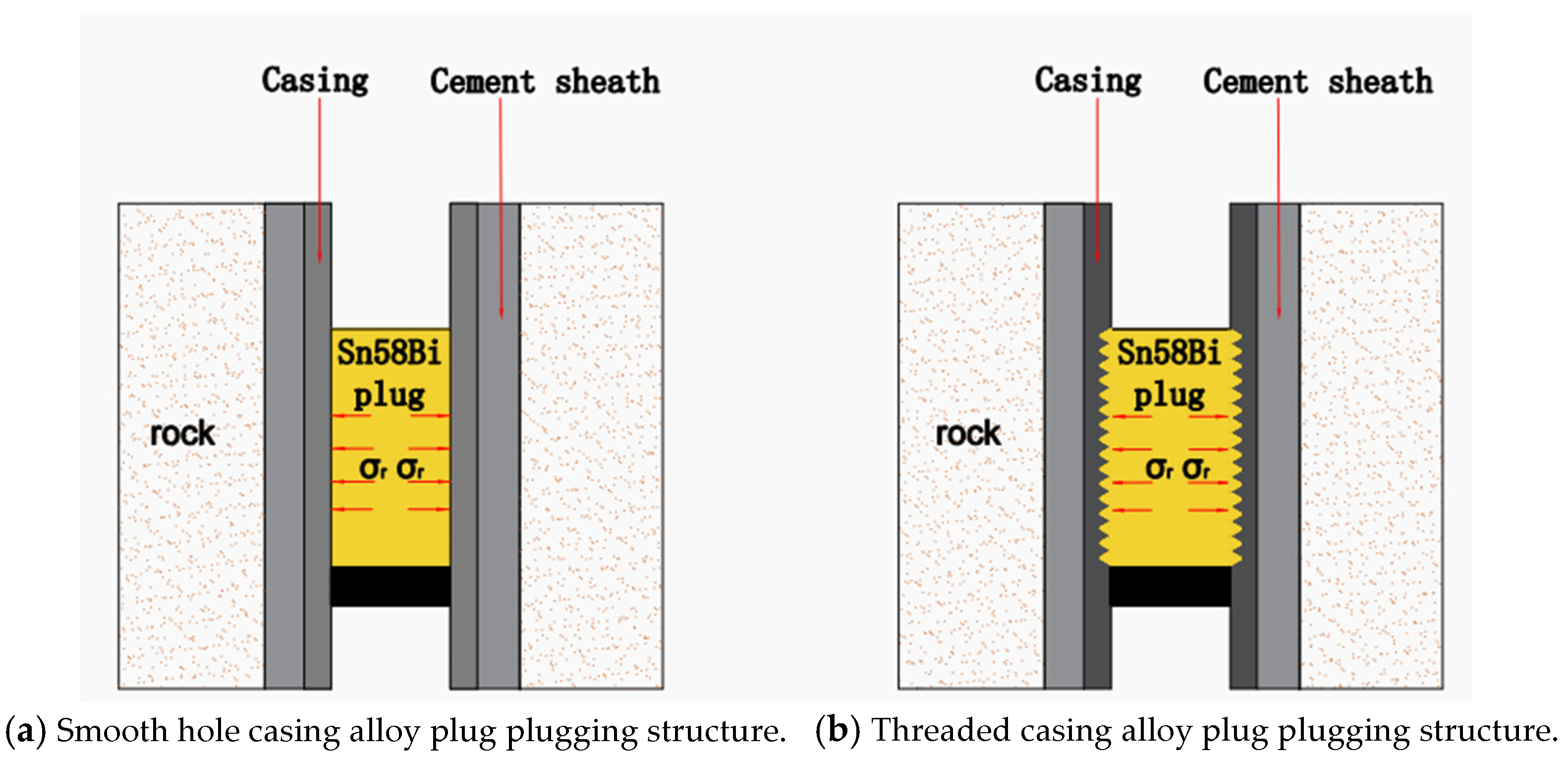
Figure 1. Schematic diagram of downhole alloy plug and casing structure.
Applsci 14 09249 g001
Figure 2. Experimental casing and surface roughness measuring instrument TR300.
Applsci 14 09249 g002
Figure 3. Waveforms of internal surface roughness of five different types of casing.
Applsci 14 09249 g003
Figure 4. Physical and schematic diagrams of alloy plug molding experiments.
Applsci 14 09249 g004
Figure 5. Schematic diagram of molded 100 mm alloy plug samples with internal structure.
Applsci 14 09249 g005
Figure 6. General diagram of gas seal test experiment.
Applsci 14 09249 g006
Figure 7. Structure of the gas sealing performance test setup.
Applsci 14 09249 g007
Figure 8. Observations of alloy plug gas leakage sources.
Applsci 14 09249 g008
Figure 9. Optical microscope observations of threaded casing alloy plug samples with different plugging lengths.
Applsci 14 09249 g009
Figure 10. Schematic diagram of roughness measurement of wire-cut alloy plug sample.
Applsci 14 09249 g010
Figure 11. Roughness waveform of alloy plug sample after wire cutting.
Applsci 14 09249 g011
Figure 12. Gas sealing performance of threaded tube alloy plugs at different ambient temperature conditions.
Applsci 14 09249 g012
Figure 13. Schematic diagram of the path of the alloy plug–casing interface.
Applsci 14 09249 g013
Figure 14. Variation of gas sealing performance of casing alloy plugs with different roughness at 30 °C with increasing length-to-diameter ratio.
Applsci 14 09249 g014
Table 1. The properties of Sn58Bi alloys [13,14].
PropertiesMelting Point (°C)Surface Tension at 155 °C (mPa·s)Thermal Expansion Coefficient (°C−1)Volume Change
(from Liquid to Solid)
Density at
21 °C (g/cm3)
Value1384381.5 × 10−7+0.77%8.72
Table 2. Parameters of the casing used in the experiment.
Casing TypeRoughnessNominal Diameter
(mm)
Pitch of Spiral
(mm)
Thread Length
(mm)
Smooth casingRa3.2---
Medium-roughness casingRa6.3---
High-roughness casingRa12.5---
Threaded casingRa3.2843100
Threaded casingRa3.2846100
Disclaimer/Publisher’s Note: The statements, opinions and data contained in all publications are solely those of the individual author(s) and contributor(s) and not of MDPI and/or the editor(s). MDPI and/or the editor(s) disclaim responsibility for any injury to people or property resulting from any ideas, methods, instructions or products referred to in the content.