Article

A Bi-Objective Optimization Strategy of a Distribution Network Including a Distributed Energy System Using Stepper Search

1
School of Electrical and Control Engineering, North China University of Technology, Shijingshan District, Beijing 100144, China
2
Shandong Electric Power Company Haiyang Power Supply Company, Haiyang 265100, China
3
Distribution Technology Center, China Electric Power Research Institute, Haidian District, Beijing 100192, China
*
Author to whom correspondence should be addressed.
Appl. Sci. 2024, 14(20), 9480; https://doi.org/10.3390/app14209480
Submission received: 26 August 2024 / Revised: 11 October 2024 / Accepted: 14 October 2024 / Published: 17 October 2024

Abstract

:
The optimal scheduling of DES is to solve a multi-objective optimization problem (MOP) with complex constraints. However, the potential contradiction between multiple optimization objectives leads to the diversity of feasible solutions, which has a serious impact on the selection of optimal scheduling strategies. Therefore, a stepper search optimization (SSO) method has been proposed for a bi-objective optimization problem (BiOP). Firstly, a constrained single-objective optimization problem (CSiOP) has been established to transform a BiOP and describe an accurate pareto front curve. Then, based on the characteristics of pareto front, the rate of the pareto front is analyzed by the SSO, and the best recommended solution of the BiOP is obtained. Finally, in the IEEE 33 with a DES simulation, by comparing other methods, the SSO method can better control the bi-objective optimization results to be 1–2.5 times as much as the optimal result under each single optimization objective and avoid the imbalance between the two optimization objectives. Additionally, the optimization speed of the SSO method is more than 10 times faster than that of the non-dominated sorting genetic algorithm (NSGA). Further, the SSO method will provide a novel idea for solving MOP.

1. Introduction

In modern power systems, power generation systems and power consumption units with different characteristics have entered the power grid on a large scale, which puts forward higher requirements for the power balance and stable operation of the power grid [1]. In addition, under the premise of ensuring the stable operation of power supply, transmission and consumption, the optimal scheduling of a distributed energy system (DES) needs to take into account multiple objectives such as its economy and application performance [2,3], but there are often contradictions between these objectives, which results in a complex and difficult optimization process of scheduling strategies [4]. Therefore, how to balance the conflicts between multiple optimization objectives and form a reasonable optimal scheduling strategy is a key issue that restricts the further application of the distributed energy system.

1.1. Literature Review

The optimal scheduling problem of a DES is a typical multi-objective optimization problem (MOP) with constraints, characterized by the optimal control of various operating indexes under the constraints of the actual operating boundary of the system. Regarding the solution of the MOP, some experts from various countries have carried out a large number of studies [5,6,7]. In [8], a non-dominated sorting genetic algorithm (NSGA) is proposed to achieve the optimization of operating costs, labor efficiency and the penalty cost of pollutant gas emission in an integrated park scenario, obtaining an effective non-dominated solution set. Reference [9], after applying an NSGA to obtain the set of non-dominated solutions, proposes to utilize an approximate ideal solution sorting method to obtain scheduling instructions including wind farm (WF), photovoltaic station (PV), battery energy storage system (BESS) and load. Similarly, reference [10] evaluates the optimal capacity allocation scheme of an energy storage system (ESS) from two aspects of balancing the reliability and economy of the power grid by using the method of approximate ideal solution sorting. Reference [11] combines the improved artificial bee colony (ABC) algorithm with the entropy weight method to recommend an optimal allocation scheme for the energy storage system. Reference [12] uses the genetic algorithm (GA) for a multi-objective optimization of the three parameters in combined cycle power plants to determine and recommend optimal values. The characteristic of these methods is to leverage the global optimization ability of swarm intelligence optimization algorithms and, after obtaining numerous non-dominated solutions, use evaluation methods to recommend the final result. The disadvantage of this approach is that non-dominated solutions tend to be limited and few in number, while recommended solutions are directly affected by different evaluation methods.
Another way to solve an MOP is to combine multiple optimization objectives into a joint optimization objective, transforming it into a single-objective optimization problem (SiOP), of which one of the most common ways is to combine multiple optimization objective functions using summation [13,14]. For example, in the economic optimization of electric power, reference [15] equates the power loss to an operating cost and then sums it with the economy of other operating units in the system to form an SiOP. Reference [16] transforms the aging damage of the charging and discharging power process of the BESS into the operating cost of the BESS, accomplishing the union of multiple optimization objectives. References [17,18] equate the amount of discarded new energy as an economic loss for electricity applications, transforming the problem of new energy consumption into an optimization problem for economic objectives. Similarly, in references [19,20], an economic benefit of the reserve power from the power generation unit has been established to decide the operation status of the power grid and achieve the optimization of scheduling strategies for multiple types of energy. Other than converting various optimization objectives into the economic indicators mentioned above, some studies have achieved the reasonable addition of multiple optimization objectives by eliminating the physical meaning of each optimization objective function or allocating weights [21,22]. For example, references [23,24] combine multiple optimization objective functions through a weight allocation method, but the subjective weight values defined by users are easy to cause a lack of objectivity. By analyzing the indicators from the application scenarios, references [25,26] have assigned the objective function weight and completed the MOP transformation based on the analytic hierarchy process and fuzzy theory, respectively. Although the above method can simply and effectively transform the MOP into a constrained single-objective optimization problem (CSiOP), there is a certain deviation in the economic equivalent accuracy of the optimization objective. Additionally, the way of the weight allocation has a great influence on the optimization results, and the current objective weight allocation method is not perfect enough.
A summary of the above studies is listed in Table 1. Several comments are concerned. (1) In a MOP, a solution set for multi-objective optimization problems can be obtained by non-dominated swarm intelligence optimization, but selecting a recommended solution is difficult. There are few studies exploring the pareto frontier morphology. (2) Few studies implement or explore the pareto frontier morphology. (3) The method of transforming a MOP into a CSiOP has been extensively studied, but there is often a lack of discussion on the effectiveness of the transformation approach.

1.2. Contributions and Paper Organization

Therefore, in the MOP exhibited by the optimal scheduling of a distributed energy system, there are two key issues that need to be solved urgently. One is how to effectively obtain a pareto front or a non-dominated solution set for multiple optimization objectives, and the other is how to obtain a reasonable and unique recommended solution in the non-dominated solution set. To solve the above problems, a bi-objective optimization method is proposed based on stepper search optimization (SSO) from the perspective of pareto front form and the changing rate. This has provided an effective and recommended solution based on the transformation and the search of the bi-objective optimization problem (BiOP). The main contributions of this paper are summarized as follows.
(1)
The SSO method has transformed a BiOP into a CSiOP by changing the boundary conditions. It can effectively describe the pareto front of the BiOP, which helps to solve the problem of how to choose the recommended solution on the pareto front.
(2)
For the first time, the SSO method adopts stepper search on the pareto front to form the best-recommended solution of a BiOP based on the change rate of each non-dominated solution, with a novel approach being provided for selecting the recommended solution of a BiOP.
The organization of the manuscript is as follows. In the first section, the mathematical model of a DES is established, including the constraints of the operation process and two optimization objective functions. Then, the problems in the process of bi-objective optimization are analyzed, and the analysis process and implementation flow of the SSO method are shown. In the third section, based on the simulation example of IEEE 33 defined by the Institute of Electrical and Electronics Engineers (IEEE), the SSO method is compared and discussed with other methods. Finally, in the fourth section, the relevant conclusions and future research directions of this paper are given.

2. Mathematical Model of Distribution Network

2.1. The Operation Constraints of Distribution Network

Figure 1 shows a DES under an IEEE 33 distribution network including two photovoltaic power stations, two wind power generation stations, distributed generation (DG) and a BESS. It can be seen that there are multiple energy units scattered throughout the IEEE 33 distribution network. The distributed photovoltaic and wind-power generation stations provide green energy for the DES, while DG and ESS are used to ensure the energy balance and economic of the DES. In the application of the DES, certain operation constraints should be guaranteed, including the interactions of power, current and voltage among power nodes in the system, which conform to some basic physical laws such as energy conservation and node voltage equations [27]. These constraints for operation can be roughly divided into two categories, equality constraints and inequality constraints.
Firstly, in the operation process of the DES mentioned above, the equation constraints satisfied are the power-balance equation as shown in Equation (1). At time t, PDG,i(t), PESS,i(t) and PNew,i(t) respectively represent the active power of the DG, ESS and new energy station on the i-th power node. Additionally, QDG,i(t) and QESS,i(t) are the reactive power of the DG and ESS. Similarly, the branch current and active and reactive power have been described as Ii,j(t), Pi,j(t) and Qi,j(t), respectively.
P DG , i t + P ESS , i t + P New , i t P LOAD , i t = j = 1 N b P i , j t j = 1 N b I i , j t R i , j Q DG , i t + Q ESS , i t Q LOAD , i t = j = 1 N b Q i , j t j = 1 N b I i , j t X i , j
where PLOAD,i(t) and QLOAD,i(t) are the active and reactive power of the load. Ri,j and Xi,j are the resistance and reactance between the j-th and the i-th power node. The number of power nodes is Nb.
Then, Ohm’s law equation for each node in the power grid is considered as shown in Equation (2). Ui(t) is the voltage of the i-th power node.
U i t = U j t + I i , j t × R i , j 2 + X i , j 2 2 × P i , j t × R i , j Q i , j t × X i , j
Meanwhile, to balance the energy of the ESS during each typical day, Equation (3) represents the relationship between the energy state of the ESS and the charging and discharging power. At time t, the state of energy (SOE), the charge and discharge active power of the ESS on the i-th power node are CSOE,i(t), P ESS_c , i (t) and P ESS_d , i (t). In a typical day, the starting and ending SOEs of the ESS are CSOE,i(0) and CSOE,i(T).
C SOE , i t + Δ t = C SOE , i t P ESS _ d , i t / η d , i + P ESS _ c , i t × η c , i × Δ t × 100 / S ESS , i N
where, on the i-th power node, the initial SOE, rated power, rated capacity and charging and discharging efficiency of the ESS have been described as C SOE , i init P ESS , i N , S ESS , i N , ηc,i and ηd,i.
Equation (4) shows the energy balance relationship and initial state of charge in each typical day. The starting and ending SOEs of the ESS are CSOE,i(0) and CSOE,i(T).
C SOE , i 0 = C SOE , i T = C SOE , i init
The energy storage output power has been defined by Expression (5).
P ESS , i t = P ESS _ d , i t + P ESS _ c , i t
In addition to meeting the above equation constraints, the actual operation of the distributed energy system needs to meet some inequality constraints [28,29]. Firstly, the actual power must be less than or equal to its rated power for DG as shown in Inequality (6). The maximum and minimum active power of the i-th DG are P DG , i min and P DG , i max , respectively. Then, Q DG , i min and Q DG , i max are the maximum and minimum active power.
P DG , i min P DG , i t P DG , i max Q DG , i min Q DG , i t Q DG , i max
Similarly, the Inequality (7) represents that the actual power is less than or equal to its rated power for ESS, and the SOE range of the i-th ESS is [ C SOE , i L , C SOE , i D ]. At time t, the binary variables indicating the charging and discharging statuses of the i-th ESS have been defined by u i c (t) and u i d (t). They have limited the ability of the ESS to charge and discharge energy at the same time.
0 P ESS _ d , i t u i d t × P ESS , i N u i c t × P ESS , i N t P ESS _ c , i t 0 u i c t + u i d t 1 u i c t = 0 o r 1 u i d t = 0 o r 1 C SOE , i L C SOE , i t C SOE , i U
In terms of new energy generation station, the output power must be less than or equal to the maximum power that can be output from the new energy field station at the current moment as shown in Inequality (8). The maximum active power of the i-th new energy generation station has been described as P New , i ref (t).
0 P New , i t P New , i ref t
Meanwhile, considering the requirements of power grid operation, it is necessary to limit the voltage of power grid nodes and branch currents, as shown in Inequality (9) where the maximum value of the node voltage and the branch current have been defined as Umax and Imax, respectively. The minimum value of the node voltage is Umin.
U min U i t U max 0 I i , j t I max
In addition to the above common inequality constraints, the distributed power supply and energy storage system can output both active and reactive power, and the actual output of active and reactive power shows a quadratic inequality relationship with the rated power of DG and ESS, as shown in Inequality (10) where the rated power of the DG and ESS on the i-th power node are S DG , i N and P ESS , i N , respectively. ||·||2 represents the 2-norm of the vector.
P DG , i t Q DG , i t 2 S DG , i N P ESS , i t Q ESS , i t 2 P ESS , i N
The last class of inequality constraints derives from a relaxation process for nonlinear equality constraints, such as the i-th node power balance equation P2i,j(t) + Q2i,j(t) = Ii,j(t) × Ui(t). This type of constraint exhibits the nonlinearity of the multiplication between the variables Ii,j(t) and Ui(t), and this equation will be relaxed as a quadratic inequality form shown in Inequality (11).
2 × P i , j t 2 × Q i , j t I i , j t U i t 2 I i , j t + U i t
The following can be seen from the above constraints: (1) The coupling relationship between the components of a DES is significant, and the output of each subsystem will have a direct impact on the operating range of other subsystems. (2) The actual operation of a DES contains a large number of equations, inequalities and quadratic constraints, and the actual operating boundaries of the system are relatively complex. (3) There are many discrete variables of type 0–1, such as u i c and u i d , and continuous variables in the constraints forming a mixed variable optimization problem. The continuous variables have included PDG,i, PESS,i, PNew,i, QDG,i, QESS,i, Ii,j, Pi,j, Qi,j, Ui, CSOE,i, P ESS_c , i and P ESS_d , i .

2.2. The Objective Function of Distribution Network

Section 2.1 shows the operational constraints of the DES, and this section will establish the optimization objective function of the DES. There are many elements in a DES, and a variety of different optimization objectives are established from the perspectives of grid performance and economy, such as grid loss, node voltage deviation, new energy utilization rate, system operating cost and so on. However, the SSO method in this paper is more friendly for the BiOP. Therefore, this paper takes the two optimization objectives of grid loss and system operating cost as examples to carry out the subsequent analysis. It should be noted that these two objective functions are only listed for the purpose of illustrating the methodology of this paper, which does not mean that the SSO method is limited to optimizing the following functions.
(1)
To reduce the power line loss of the DES, the first optimization objective function J1 is established, as shown in Expression (12), and is a key index that effects the transmission efficiency of the power grid.
min J 1 = 1 2 t = 1 T i = 1 N b j = 1 N b i i , j 2 t × R i , j 2 + X i , j 2
(2)
To reduce the operating costs of the DES, the second optimization objective function J2 is established including the cost of DG, ESS and the new energy generation station, as shown in Expression (13), where SDG,i, S ESS , i and S New , i respectively represent the electricity consumption of the i-th DG, ESS and new energy during time period Δt. S DG , i = P DG , I × Δt, S ESS , i = P ESS , I × Δt and S New , i = P New , I × Δt. In this paper, Δt = 1 h. Then, where k1,I, k2,I and k3,i respectively represent the cost coefficient of DG [30,31], ¥/kWh2, ¥/kWh, ¥. Significantly, k1,i represents the cost coefficient of the square of the active power of DG. Therefore, the unit of coefficient k1,i is ¥/kWh2. The levelized cost coefficient of the ESS and the new energy generation station have been defined as k4,i and k5,i, ¥/kWh.
min J 2 = t = 1 T i = 1 N b k 1 , i S DG , i 2 t + k 2 , i S DG , i t + k 3 , i + k 4 , i S ESS , i t + k 5 , i S New , i t
The following can be seen from the above optimization objectives: (1) The physical dimensions of the two optimization objectives are different, so it is difficult to directly compare and analyze the importance between them, and it is not convenient to transform them into a single optimization objective by adding weights. (2) The two optimization objectives are used to evaluate the two aspects of the operation of the DES and do not have dominance, which means that the two optimization objective functions are equivalent in the distributed energy system. (3) Both objective functions exhibit quadratic form, which implies that the optimization and control of the DES is a multi-objective quadratic planning problem.

3. The Problem and Solution of the BiOP

3.1. The Problem of the BiOP

The first section shows that the optimal control problem of the DES can be described as a bi-objective quadratic programming problem with a large number of complex constraints. This mathematical optimization problem can be described as Expressions (14) and (15), where X = [x1, x2, …, xm] is a vector composed of optimization variables xi, i = 1, 2, …, m, while f1(X) and f2(X) respectively represent two optimization objective functions, gk(X) represents the k-th inequality constraint, hl(X) represents the l-th equality constraint and x i lb and x i ub respectively represent the lower and upper bounds of the optimization variable xi.
minimize X F X = f 1 X , f 2 X
Subject to g k X 0 , k = 1 , 2 , , K h l X 0 , l = 1 , 2 , , L x i lb x i x i ub , i = 1 , 2 , , m
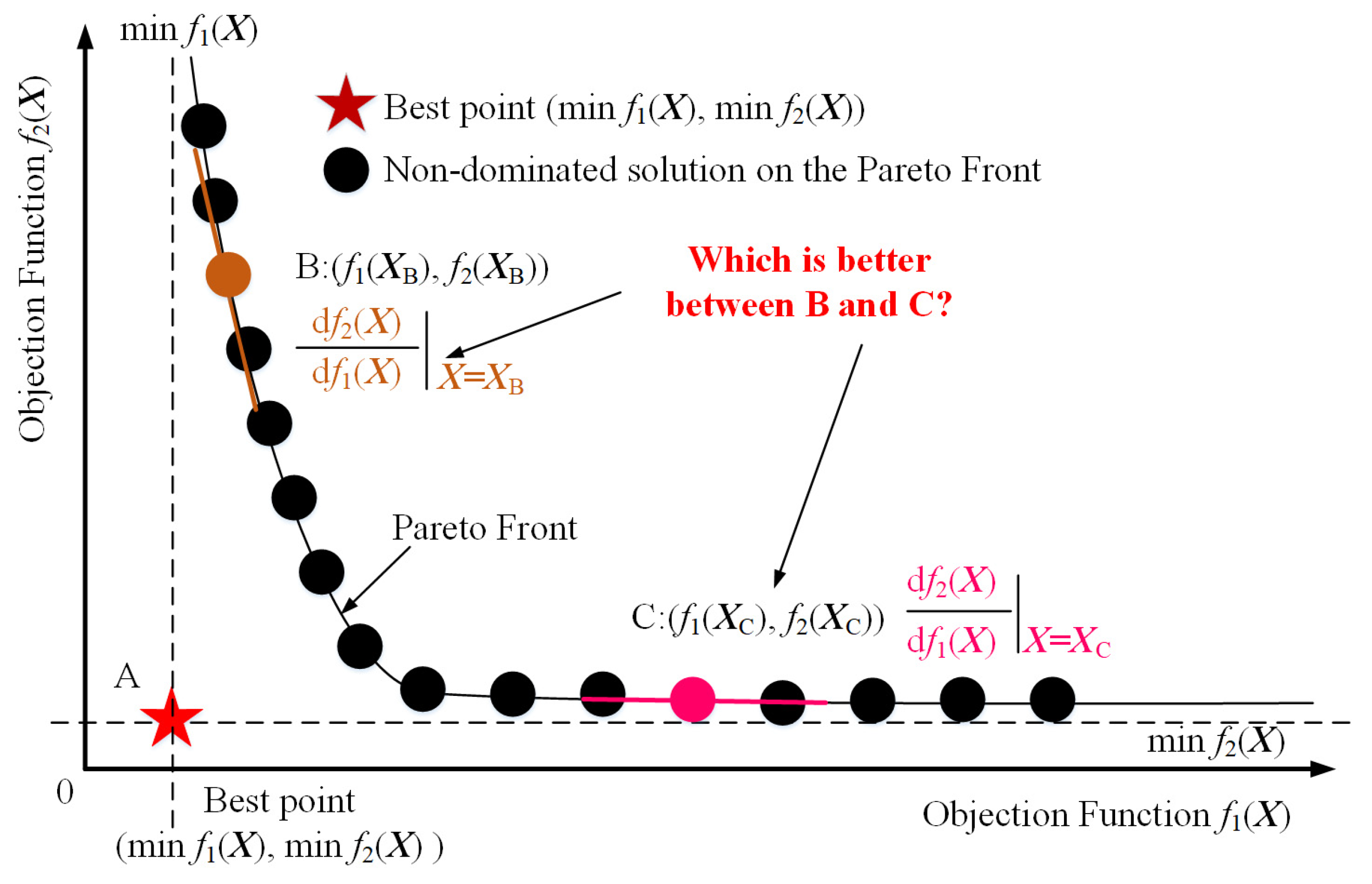
In a MOP, there is generally no solution to ensure that both optimization objectives are the most global optimal. The way to solve such optimization problems is to use the pareto optimization method to obtain a series of non-dominated solutions, and there is no definite dominance relationship between different optimization solutions rather than a global optimal solution. Figure 2 shows the results of analyzing pareto optimality using two optimization objectives as examples.
From Figure 2, it can be observed that if each objective is independently optimized, a global optimum can be obtained. The points marked by these global optimum values are defined as the optimal points in the multi-objective function space, such as point A in the figure. However, this optimal point is not achievable in multi-objective optimization problems. Pareto optimization is used to obtain a series of non-dominated solutions that form a convex surface in the space of multi-objective functions, which is the pareto front. Obviously, it is difficult to choose the most reasonable solution among many non-dominated solutions on the pareto front. However, it is worth thinking about in this paper that non-dominated solutions on the pareto front, such as points B and C, show great differences in their slopes df1(X)/df1(X)|X = XB or XC. In the neighborhood of point B, when f1(X) changes slightly, f2(X) will change dramatically. In the neighborhood of point C, on the contrary, when f1(X) changes greatly, f2(X) hardly changes. It is from this phenomenon that this paper carries out a study from the perspective of the degree of the change of the two optimization objective functions and proposes a bi-objective optimization method based on stepper search to complete the problem of selecting the non-dominated solutions on the pareto front.
Based on the above analysis, it can be seen that the method proposed in this paper needs to address the following two issues. (1) How to define the change in the slope of the pareto front. (2) How to find the point with the largest slope change. It is very unfortunate that pareto front parsing expressions cannot be built in the currently available methods, and the above problems can only be solved by means of numerical analysis. Therefore, in the SSO method, the most crucial part is to transform the description form of the BiOP, and the transformed optimization problem is described as shown in Expression (16).
minimize J X = r 2 | r 1 = c Subject to g k X 0 , k = 1 , 2 , , K h l X 0 , l = 1 , 2 , , L x i lb x i x i ub , i = 1 , 2 , , m f 1 X | min f 1 X | r 1 + min f 1 X f 2 X | min f 2 X | r 2 + min f 2 X
Expression (16) has introduced two optimization variables r1 and r2, which respectively represent the deviation margins between the two optimization objectives and their respective optimal values, and transforms the optimization problem described in Expression (14) into a constraint inequality. The optimization goal J(X) = r2|r1 = c means that the problem of minimum optimization deviation margin r2 is solved under the condition of r1 = c, where c represents a constant value that can be changed. Obviously, the optimization result of Expression (16) will converge to min(J1(X)) when the parameter c→0, while the optimization result of Expression (16) will converge to min(J2(X)) when the parameter c→∞. According to the optimization model described in Expression (16), when the parameter c changes from 0 to ∞, the pareto front of the dual optimization objectives described in Expressions (14) and (15) can be formed.

3.2. A Bi-Objective Optimization Method Based on SSO

According to the mathematical model described in Expression (14), this paper has proposed a SSO method for solving the BiOP. Figure 3 shows the stepper search process of the SSO method. Suppose the current search point is a, whose coordinates are obtained by using the single-objective optimization model described in the interior-point method optimization Expression (14) under the condition r1 = c, that is, point a = min(r2|r1 = c).
Modifying the value of r1 in the direction of the objective function f1(X) with a step size Δc, r1= r1 + Δc, it can be seen that the point a will move to the point c, min(r2|r1 = c + Δc). At this point, if the absolute value of the change in the direction of the objective function f2(X) is greater than or equal to min(f2(X)) × Δc, which means that the change in the optimization objective function f2(X) is greater under the change in the objective function f1(X), then the point c will be the starting point of the next search. If the absolute value of the change in the direction of the objective function f2(X) is less than min(f2(X)) × Δc, then this means that the change in the optimization objective function f2(X) is less than the change in the objective function f1(X), and the search step should be narrowed down (the dichotomy can be utilized to change Δc), that is, r1 = r1 + 0.5 × Δc. Additionally, the SiOP described in Expression (14) is optimized once again by using the interior point method, and point a will move to min(r2|r1 = c + 0.5 × Δc) at point b. Again, compare the amount of change in the optimization objective functions f1(X) and f2(X). By continuously completing the above process, when the deviation value of the variation of the optimization objective functions f1(X) and f2(X) is small or reaches the set maximum number of iterative searches, the search process will be stopped, and the result of the last search will be the final optimization result. Based on the stepper search approach depicted in Figure 3, the pseudo-code of the SSO algorithm has been listed in Algorithm 1.
Algorithm 1 Pseudo code of the SSO method.
Input: In the DES described in this article, the BiOP has been shown in mathematical relation (1)~(13), and the mathematical model for transforming the BiOP of the DES is shown in Expression (16). The initial step parameter Δc and the deadline of stepper search are defined. The deadline of the stepper search is the maximum number of iterations Nmax and stop threshold λ. Assuming that the iteration N is 0,
  • Optimize two single optimization objective functions independently. The minimum value of each optimization objective is min(J1(X)) and min(J2(X)), respectively;
  • r 1 N ←Δc optimize Expression (16), and min( r 2 N | r 1 N ) is obtained.
  • Calculate J 1 N (X) and J 2 N (X) under the above r 1 N and r 2 N condition,
  • While N < Nmax
  • r 1 N + 1 r 1 N + Δc optimize Expression (16), and min( r 2 N + 1 | r 1 N + 1 ) is obtained.
  • Calculate J 1 N + 1 (X) and J 2 N + 1 (X) under the above r 1 N + 1 and r 2 N + 1 condition;
  • if abs(| J 1 N + 1 (X) − J 1 N (X)|/|min(J1(X))| − | J 2 N + 1 (X) − J 2 N (X)|/|min(J2(X))|) ≤ λ or N > Nmax
  • break;
  • else
  • if | J 1 N + 1 (X) − J 1 N (X)|/|min(J1(X))| ≤ | J 2 N + 1 (X) − J 2 N (X)|/|min(J2(X))|
  • Δc ← Δc;
  • NN + 1;
  • else
  • NN;
  • Δc←Δc/2;
  • end
  • end
  • end
  • Output: ( J 1 N (X), J 2 N (X)) and X under the r 1 N and r 2 N condition.

4. Case and Discussion

4.1. Case Condition

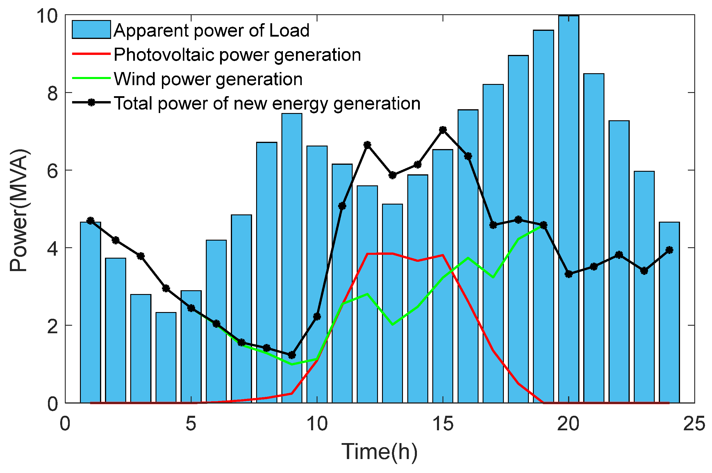
To analyze and validate the SSO methodology, this paper has carried out the analysis based on the DES in the IEEE 33 distribution network as shown in Figure 1. And the lithium-ion battery energy storage system has been adopted as the BESS in this paper. Table 2 has represented the case parameters and condition of the power grid, DG, photovoltaic power station, wind power station and BESS. The computational environment of this example is Matlab 2020a under Win10 system, the computer memory is 32 G, the CPU is Intel Core i7, the main frequency is 2.3 GHz and the number of cores is 16. Figure 4 shows the power curves of the power load and photovoltaic and wind power stations in a typical day system. The time interval Δt = 1 h, and the typical day T = 24 h.
In Table 2 and Figure 4, it can be seen that the apparent power of the load is less than 10 MVA, and the total rated power of new energy stations is greater than 10 MVA. Additionally, the apparent power of the load is much greater than the actual maximum output power of the new energy stations at 5–11 h and 16–24 h, respectively. It means that there is an imbalance between power supply and consumption in the distribution network system and a reasonable control of BESS and DG is necessary.
Meanwhile, this paper compares the SSO method with other common multi-objective optimization methods. Method 1 is an equal-weight summation method, method 2 is a Euclidean distance minimization method, and the optimization objective functions are shown in Expressions (17) and (18), respectively. In addition, the constraint conditions for method 1 are shown in Expression (15), and the constraint conditions for method 2 are shown in Expression (16). Further, as the method 3, the traditional NSGA method combined with TOPSIS [9] has been used for a comparison of the proposed methods. The maximum iterative number is 30, and the number of individuals is 20 in the population.
minimize J X = J 1 X min J 1 X + J 2 X min J 2 X
minimize J X = r 1 2 + r 2 2

4.2. Result Analysis

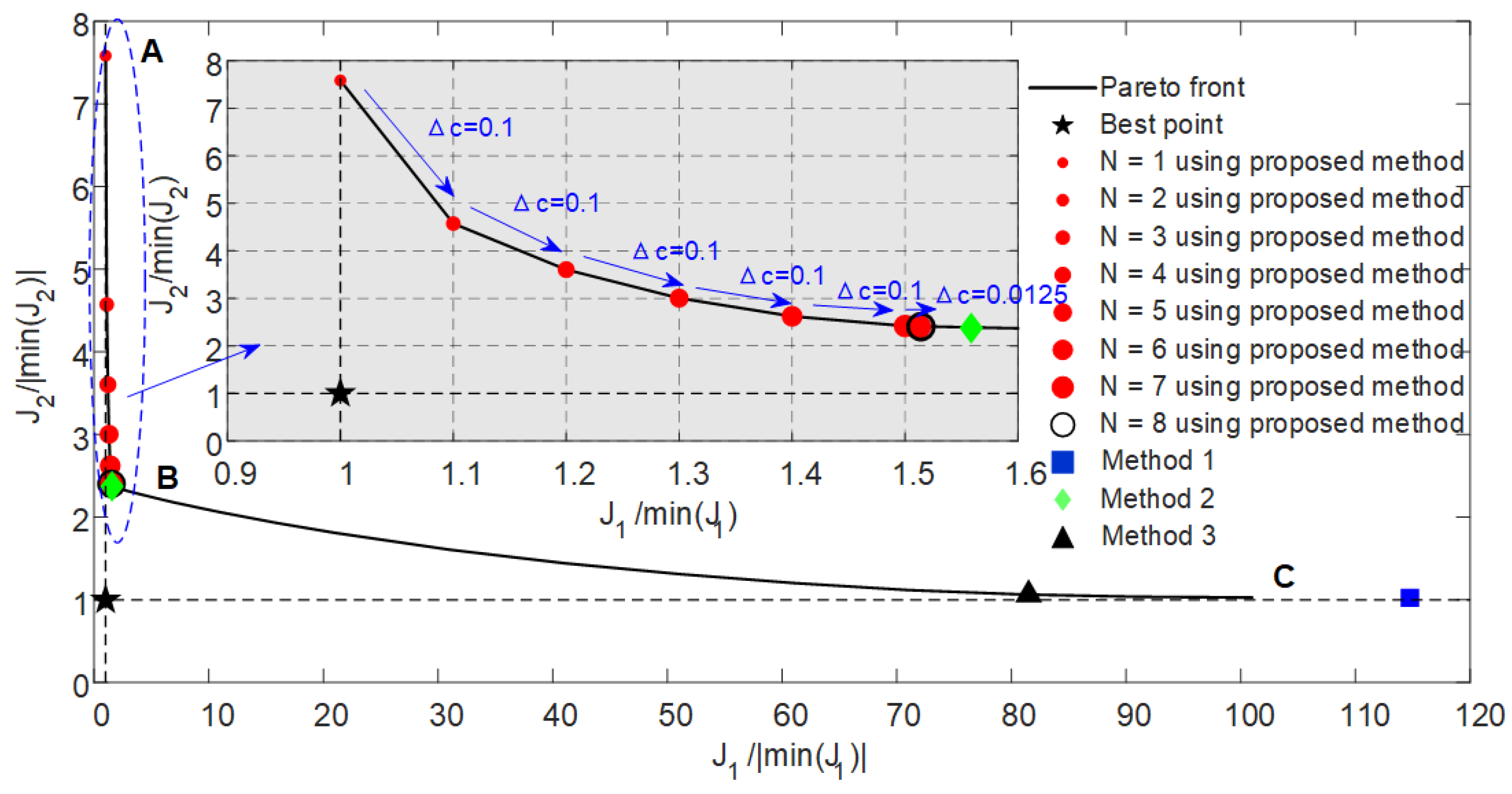
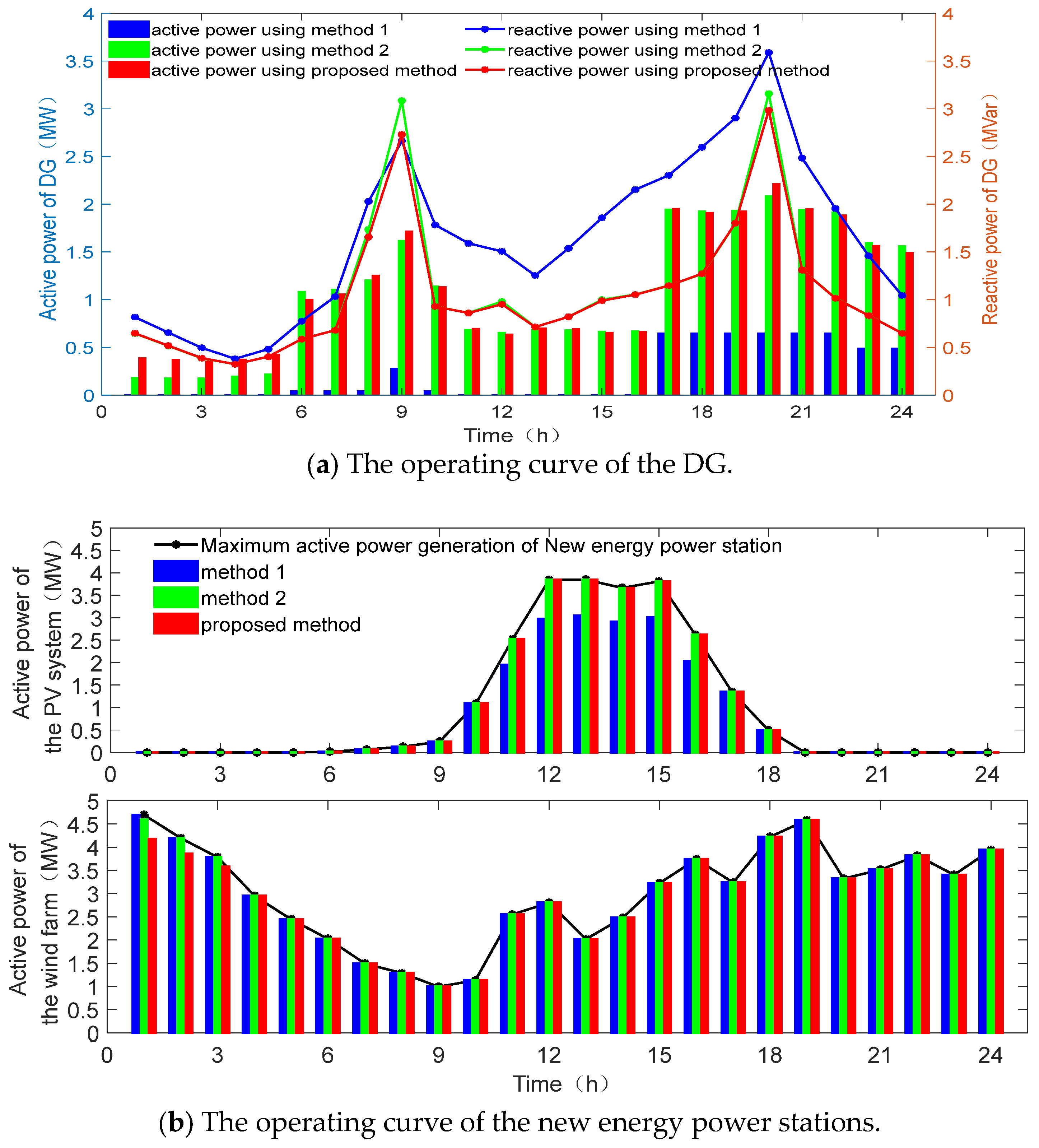
With the above simulation parameters, a single objective optimization is performed based on the two objective functions of the DES mathematical model described in Section 1 to obtain the minimum values min(J1) = 0.0294 and min(J2) = 11,584.32. Table 3 demonstrates the comparison of the two objective function values under optimization with a single objective, method 1, method 2, and the SSO method. Figure 5 shows the optimization results under three different methods and the stepper search process of the SSO method. Figure 6 shows the differences of the optimization scheduling results between three different methods from four perspectives: distributed power, new energy generation power stations, energy storage system and grid node voltage.
Table 3 presents the following: (1) Optimizing with a single objective guarantees that the results obtained will be optimal for that metric, but the other metric will be so far from the optimal position that it will not be possible to balance the two optimization objectives, and the results obtained will be very poor. (2) Compared to single-objective optimization, the optimization result obtained by using method 1 and 3 increases only by 0.0248 and 0.0637 in the J2/min(J2) direction but decreases by 25.9617 and 59.2115 in the J1/min(J1) direction, respectively. It means that the optimization result is better than the single-objective optimization approach in terms of the whole system but still exhibits poorer performance in the J1/min(J1) direction. (3) Compared to method 1, although method 2 and the SSO method decrease by 1.3508 and 1.3799, respectively, in the J2/min(J2) direction, they increase by 113.1911 and 113.2356, respectively, in the J1/min(J1) direction, improving approximately 80 times. It means that the scheduling strategies based on these two methods will be more conducive to the overall performance of the system. (4) Compared to method 2, the SSO method decreases by 0.0291 in the J2/min(J2) direction and increases by 0.0445 in the J1/min(J1) direction. Although this numerical change is small, it achieves approximately 1.5 times the benefit, which means that the SSO method is slightly better than method 2. (5) In terms of solving time, the proposed method is superior to method 3 and reduces the solution time by more than 10 times, but it is inferior to other methods. The reason for the above results is that the proposed method and method 3 have iterative processes, and there are more iterations required in method 3.
Figure 5 shows the distribution characteristics of different methods on the pareto front and the stepper search process of the SSO method in the coordinate system composed of (J1/|min(J1)|, J2/|min(J2)|). From the figure, it can be observed that (1) the two optimization objectives show significant contradiction, that is, as the value of one optimization objective decreases, the value of the other optimization objective increases. (2) In the coordinate system composed of (J1/|min(J1)|, J2/|min(J2)|), the pareto front shows two parts with significant slope differences, namely, the AB section and BC section. In the AB section, as J1 slowly increases, J2 rapidly decreases, which means that by alleviating the requirements for target J1, greater benefits can be obtained on target J2. On the other hand, in the BC section, as J1 increases significantly, J2 slowly decreases, which means that the substantial reduction of the requirements for the target J1 has limited improvement in the direction of the target J2. Therefore, the optimization results of method 1 and 3 are located in the BC section and are far from point B, which is bad for the whole system. Meanwhile, the search results of both method 2 and the SSO method are close to point B, the point of the slope mutation of the pareto front, which means that the results of these two methods are better for the overall system. (3) The search process of the SSO method takes Δc = 0.1 as the step, and, after updating five times, it gradually decreases for three times, resulting in Δc = 0.0125, and then abs(J1/|min(J1)| − J2/|min(J2)|) < λ is searched. This implies that the stepper search method proposed in this paper is effective and can search for the recommended solution quickly.
From the operating curves of the DG presented in Figure 6a, the curves of method 2 and the SSO method are basically the same, and the trend of the output power during a typical day is basically consistent with the load power demand, whereas in method 1, in order to significantly reduce power loss (optimization objective J1), the distributed power supply continuously outputs a large amount of reactive power and reduces the active power output. From the comparison of the operating curves from PV and wind power generation system shown in Figure 6b, the actual power of wind power generation has been well consumed based on the three scheduling strategies, but there is a phenomenon of photovoltaic power abandonment in the application of method 1, which is concentrated in the peak of PV power generation and the low valley of load power consumption between 12~15 h. Additionally, it can be seen that method 2 and the SSO method are better than method 1. Figure 6c shows the output active power curve and energy state of the BESS. Between 0:00 and 6:00, the BESS takes the initiative to charge and dissipate the wind power generation that is larger than the load demand. Between 6:00 and 11:00, the load active power is greater than the maximum output power of the new energy, and the BESS discharges to support the load power demand. Between 11:00 and 16:00, due to more photovoltaic power generation, the new energy generation is greater than the load demand, and the BESS is reasonably charged again, ready to cope with the next decline in photovoltaic power generation caused by the difference between the load power and the new energy power supply. The BESS has solved the power balance problem and ensured the economic operation of the DES. Figure 6d shows the voltage curves of each node from the power grid at different times under different optimization methods. It can be seen that compared with method 1, the voltage of each node from the power grid is close to 1.21 (the square of 110% of the reference voltage) in the whole time period under method 2 and the SSO method, thus reducing the line current and power loss.

4.3. Discussion

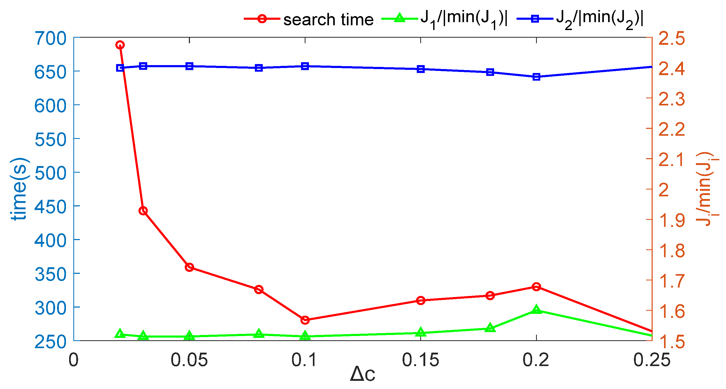
Firstly, this section discusses the influence of the step parameter Δc of the SSO method on the search stability and speed. Table 4 shows the calculation time and optimization target value of the SSO method under the step parameter Δc, and Figure 7 shows the change process of the corresponding curve.
Table 4 and Figure 7 show that (1) with the decrease in step parameter Δc, the solution time of the SSO method increases; especially when Δc ≤ 0.03, the solution time almost doubles. However, when the step parameter Δc is large, Δc ∈ [0.08,2.5], the solution time of the SSO method fluctuates in a small range between 250~350 s. (2) With the decrease in step parameter Δc, the fluctuation ranges of J1/min(J1) and J2/min(J2) are 1.51~1.60 and 2.37~2.40, respectively. This means that the accuracy of the SSO method is insensitive to the step parameter Δc. Therefore, in the SSO method, a larger step size can be selected for calculation by selecting the step parameter Δc.
Then, to verify the applicability of the SSO method, this section establishes two optimization objectives J3 and J4 from the aspects of node voltage and new energy station in the DES, which are defined as shown in Expressions (19) and (20). At time t, the i-th node voltage and the power have been defined as Vi(t) and PNew,i(t), respectively. The duration of the typical day and the number of grid nodes have been set to T and Nb. The voltage reference value is Vbase.
min J 3 = max t = 1 T max i = 1 N b abs V i 2 t / V base 2 1
min J 4 = t = 1 T i = 1 N b P New , i t
Table 5 represents the comparison results under the dual objectives of (J1, J3) with single-objective optimization, methods 1, 2 and 3 and the SSO method, respectively. Figure 8 shows the optimization results under four different methods and the stepper search process of the SSO method.
In Table 5, comparing the results of single-objective optimization, methods 1 and 2 and the SSO method can effectively balance the contradiction between the two objectives, but method 3 is not. Method 3 focuses more on the objective function J1, resulting in an excessive loss of J3. Obviously, it is not good. Compared to the other methods, using the best results of each objective function as a baseline, methods 1 and 2 decrease by 0.4879 and 0.5170 in the J1/|min(J1)| direction and improve by 0.5731 and 0.5448 in the J3/|min(J3)| direction. Then, the SSO method reduces 0.5031 in the J1/min(J1) direction and enhances 0.5581 in the J3/|min(J3)| direction. Apparently, the SSO method is more balanced. In addition, the solving time of the proposed method is superior to method 3 and reduces the solution time by about 30 times, but it is inferior to the other methods. This phenomenon and its causes are consistent with Table 3.
Figure 8 has represented the distribution characteristics of the different methods on the pareto front and the stepper search process of the SSO method under the coordinate system consisting of (J1/|min(J1)|, J3/|min(J3)|) and (J1/|min(J1)|, J4/|min(J4)|), respectively. With the first optimization objective value decreasing, the second optimization objective value rises. Further, the pareto front exhibits two components with significant differences in the slope. However, the slope changes exhibited by the pareto front are different, which means that if the above multiple objectives are comprehensively considered to form a multi-objective optimization problem, the slope changes in different objective function directions will be different.
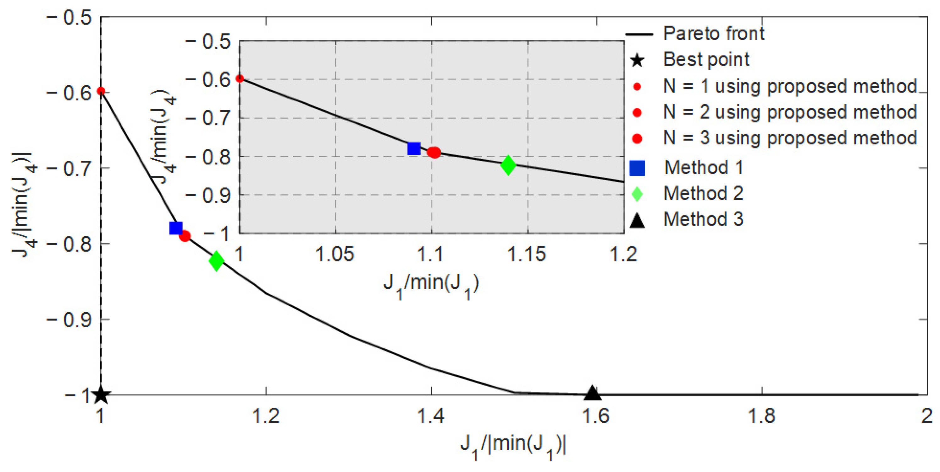
Table 6 and Figure 9 exhibit the comparison results under the dual objectives of (J1, J4) with single-objective optimization, methods 1, 2 and 3 and the SSO method, respectively.
In Table 6, the optimization results from methods 1, 2 and 3 and the SSO method have achieved effective balance in two objective function directions. It is different from Table 6. However, the results of the solving time are the same. Methods 1, 2 and 3 decrease by 0.0906, 0.13982 and 0.5947 in the J1/|min(J1)| direction and improve by 0.2205, 0.1772 and 0 in the J4/min(J4) direction. Then, the SSO method reduces 0.1016 in the J1/|min(J1)| direction and enhances 0.21 in the J4/|min(J4)| direction. The above results show that the SSO method can find equitable recommended solutions more consistently than other methods.
Compared to Figure 5 and Figure 8, the pareto front curve in Figure 9 has more stages of slope variation. The optimization results of method 3 differ significantly from other methods and is almost equivalent to the results of the single optimization objective J4. It has caused an imbalance between the two optimization objectives’ functions. Then, the result of method 1 is at the intersection of two slopes. It means that the changes in the two optimization objective functions will vary. Combining the values of Table 6, it can be seen that the optimization effect of the SSO method is better. Additionally, based on the results in Figure 5, Figure 8 and Figure 9, it can be seen that the SSO method can be applied to different forms of pareto front format. The adaptability of the method is good.

5. Conclusions

In the optimization scheduling of the DES, the SSO method has been proposed. By transforming a BiOP into a CSiOP, the pareto front of the BiOP is accurately depicted, and, according to the changing characteristics of the pareto front, the stepper search method is introduced to solve the problem of the difficulty of choosing among many feasible solutions in the MOP, obtaining a more reasonable and unique recommended solution and effectively balancing the contradiction between two optimization objectives. Furthermore, the SSO method has fewer parameters, and the parameters have less impact on the accuracy of the optimization results. The method is also highly stable. Additionally, when facing different bi-objective optimization problems, the SSO method can search for excellent recommended solutions and show good adaptability to bi-objective optimization problems.
At present, the limitation of this study is that the proposed method can only be applied to bi-objective optimization problems. Therefore, expanding the application of the SSO method to more optimization objective problems is the focus of future research. In addition, the diversity of pareto frontier morphology changes will be the core link of subsequent research.

Author Contributions

Conceptualization, S.M.; Methodology, S.M.; Validation, Z.M. and G.S.; Formal analysis, Z.M. and Y.C.; Writing—original draft, Z.M.; Writing—review & editing, S.M., Y.C. and G.S.; Visualization, Y.C.; Funding acquisition, G.S. All authors have read and agreed to the published version of the manuscript.

Funding

This work was supported in part by the Beijing Nova Program (Z211100002121081).

Institutional Review Board Statement

Not applicable.

Informed Consent Statement

Not applicable.

Data Availability Statement

The data used to support the findings of this study are available from the corresponding author upon request.

Conflicts of Interest

Author Yilin Cui was employed by the company Shandong Electric Power Company Haiyang Power Supply Company. The remaining authors declare that the research was conducted in the absence of any commercial or financial relationships that could be construed as a potential conflict of interest.

References

  1. Li, Q.; Wang, J.; Chen, J.; Ding, T.; Gu, C. A hierarchical multi-area capacity planning model considering configuration ratios of renewable energy and energy storage systems with multi-area coordination. IET Gener. Transm. Distrib. 2023, 17, 3658–3677. [Google Scholar] [CrossRef]
  2. Zeng, L.; Xu, J.; Wang, Y.; Liu, Y.; Tang, J.; Wen, M.; Chen, Z. Day-ahead interval scheduling strategy of power systems based on improved adaptive diffusion kernel density estimation. Electr. Power Energy Syst. 2023, 147, 108850. [Google Scholar] [CrossRef]
  3. Zuo, H.; Teng, Y.; Cheng, S.; Sun, P.; Chen, Z. Distributed multi-energy storage cooperative optimization control method for power grid voltage stability enhancement. Electr. Power Syst. Res. 2023, 216, 109012. [Google Scholar] [CrossRef]
  4. Ahmadi, B.; Ceylan, O.; Ozdemir, A.; Fotuhi-Firuzabad, M. A multi-objective framework for distributed energy resources planning and storage management. Appl. Energy 2022, 314, 118887. [Google Scholar] [CrossRef]
  5. Cheng, T.; Chen, M.; Wang, Y.; Li, B.; Hassan, M.A.; Chen, T.; Xu, R. Adaptive Robust Method for Dynamic Economic Emission Dispatch Incorporating Renewable Energy and Energy Storage. Complexity 2018, 2018, 2517987. [Google Scholar] [CrossRef]
  6. Di, H.; Xin, Y.; Lin, G.; Zhang, C.; Chen, H. Interval economic dispatch of multi-objective cooperative game considering wind power and energy storage connected to power grid. Control Theory Appl. 2021, 38, 1061–1070. [Google Scholar]
  7. Sandgani, M.R.; Sirouspour, S. Coordinated Optimal Dispatch of Energy Storage in a Network of Grid-connected Microgrids. IEEE Trans. Sustain. Energy 2017, 8, 1166–1176. [Google Scholar] [CrossRef]
  8. Wu, X.; Liao, B.; Su, Y.; Li, S. Multi-objective and multi-algorithm operation optimization of integrated energy system considering ground source energy and solar energy. Int. J. Electr. Power Energy Syst. 2023, 144, 108529. [Google Scholar] [CrossRef]
  9. Liu, Z.; Xiao, Z.; Wu, Y.; Hou, H.; Xu, T.; Zhang, Q.; Xie, C. Integrated optimal dispatching strategy considering power generation and consumption interaction. IEEE Access 2021, 9, 1338–1349. [Google Scholar] [CrossRef]
  10. Ma, S.; Wu, Y.; Li, J.; Hou, X.; Li, D. Optimal economic planning method of energy storage system to improve grid reliability. Acta Energiae Solaris Sin. 2024, 45, 251–262. [Google Scholar]
  11. Jiang, W.; Chen, Z. Optimization of microgrid energy storage system capacity based on improved artifical bee colony algorithm. J. Shanghai Univ. Electr. Power 2021, 37, 415–421+427. [Google Scholar]
  12. Mishra, A.; Arora, B.B.; Arora, A. Multi-Objective Optimization of an Inlet Air-Cooled Combined Cycle Power Plant. J. Therm. Sci. Eng. Appl. Trans. ASME 2023, 15, 071005. [Google Scholar] [CrossRef]
  13. Liu, Y.; Liu, Q.; Guan, H.; Li, X.; Bi, D.; Guo, Y.; Sun, H. Optimization Strategy of Configuration and Scheduling for User-Side Energy Storage. Electronics 2021, 11, 120. [Google Scholar] [CrossRef]
  14. Sun, J.; Li, Z.; Li, J.; Wu, G.; Xia, Y. Hybrid power system with adaptive adjustment of weight coefficients multi-objective model predictive control. Int. J. Electr. Power Energy Syst. 2023, 153, 109296. [Google Scholar] [CrossRef]
  15. Li, L.; Liu, P.; Li, Z.; Wang, X. A multi-objective optimization approach for selection of energy storage systems. Comput. Chem. Eng. 2018, 115, 213–225. [Google Scholar] [CrossRef]
  16. Terlouw, T.; Gabrielli, P.; AlSkaif, T.; Bauer, C.; McKenna, R.; Mazzotti, M. Optimal economic and environmental design of multi-energy systems. Appl. Energy 2023, 347, 121374. [Google Scholar] [CrossRef]
  17. Fan, W.; Tan, Q.; Zhang, A.; Ju, L.; Wang, Y.; Yin, Z.; Li, X. A Bi-level optimization model of integrated energy system considering wind power uncertainty. Renew. Energy 2023, 202, 973–991. [Google Scholar] [CrossRef]
  18. Pourghaderi, N.; Fotuhi-Firuzabad, M.; Moeini-Aghtaie, M.; Kabirifar, M.; Lehtonen, M. Optimal energy and flexibility self-scheduling of a technical virtual power plant under uncertainty: A two-stage adaptive robust approach. IET Gener. Transm. Distrib. 2023, 17, 3828–3847. [Google Scholar] [CrossRef]
  19. Qiu, Y.; Li, Q.; Ai, Y.; Chen, W.; Benbouzid, M.; Liu, S.; Gao, F. Two-stage distributionally robust optimization-based coordinated scheduling of integrated energy system with electricity-hydrogen hybrid energy storage. Prot. Control Mod. Power Syst. 2023, 8, 33. [Google Scholar] [CrossRef]
  20. Luo, Y.; Gao, Y.; Fan, D. Real-time demand response strategy base on price and incentive considering multi-energy in smart grid: A bi-level optimization method. Int. J. Electr. Power Energy Syst. 2023, 153, 109354. [Google Scholar] [CrossRef]
  21. Zhang, Y.; Zhong, K.; Deng, W.; Cheng, R.; Chen, M.; An, Y.; Tang, Y. An optimal scheduling of renewable energy in flexible interconnected distribution networks considering extreme scenarios. IET Renew. Power Gener. 2023, 17, 2531–2541. [Google Scholar] [CrossRef]
  22. Yang, H.; Wu, J.; Du, X. Thermo-economic analysis and multi-objective optimization of solar aided pumped thermal electricity storage system. J. Energy Storage 2023, 70, 107994. [Google Scholar] [CrossRef]
  23. Zhao, J.; Ju, L.; Luo, W.; Zhao, J. Reactive voltage control model and method considering partitioned dynamic reactive power reserve. Electr. Power Autom. Equip. 2015, 35, 100–105. [Google Scholar]
  24. Sagawa, D.; Tanaka, K. Machine Learning-Based Estimation of COP and Multi-Objective Optimization of Operation Strategy for Heat Source Considering Electricity Cost and On-Site Consumption of Renewable Energy. Energies 2023, 16, 4893. [Google Scholar] [CrossRef]
  25. Zhong, Y.; Huang, M.; Ye, C. Multi-objective optimization of microgrid operation based on dynamic dispatch of battery energy storage system. Electr. Power Autom. Equip. 2014, 34, 114–121. [Google Scholar]
  26. Liao, X.; Qian, B.; Jiang, Z.; Fu, B.; He, H. Integrated Energy Station Optimal Dispatching Using a Novel Many-Objective Optimization Algorithm Based on Multiple Update Strategies. Energies 2023, 16, 5216. [Google Scholar] [CrossRef]
  27. Ma, S.; Wu, Y.; Li, J.; Xiong, J.; Zeng, W. Research on optimal configuration of centralized battery energy storage for multiple service objectives. High Volt. Appar. 2023, 59, 75–86. [Google Scholar]
  28. Ma, G.; Li, J.; Zhang, X.P. Energy Storage Capacity Optimization for Improving the Autonomy of Grid-Connected Microgrid. IEEE Trans. Smart Grid 2023, 14, 2921–2933. [Google Scholar] [CrossRef]
  29. Chen, Y.; Feng, L.; Li, X.; Zoghi, M.; Javaherdeh, K. Exergy-economic analysis and multi-objective optimization of a multi-generation system based on efficient waste heat recovery of combined wind turbine and compressed CO2 energy storage system. Sustain. Cities Soc. 2023, 96, 104714. [Google Scholar] [CrossRef]
  30. Ma, S.; Wu, Y.; Jiang, Y.; Li, Y.; Sha, G. Research on two-stage optimization control method for energy storage systems based on multi service attribute utility evaluation. J. Energy Storage 2024, 46, 3041–3060. [Google Scholar] [CrossRef]
  31. Lu, M.; Guan, J.; Wu, H.; Chen, H.; Gu, W.; Wu, Y.; Ling, C.; Zhang, L. Day-ahead optimal dispatching of multi-source power system. Renew. Energy 2022, 183, 435–446. [Google Scholar] [CrossRef]
Figure 1. The DES under the IEEE 33 distribution network.
Applsci 14 09480 g001
Figure 2. Block diagram for describing a bi-objective optimization problem.
Applsci 14 09480 g002
Figure 3. Schematic diagram of the SSO method.
Applsci 14 09480 g003
Figure 4. Electricity generation and consumption curve from new energy stations and load under typical day.
Applsci 14 09480 g004
Figure 5. The distribution of optimization results (J1/|min(J1)|, J2/|min(J2)|) from the different methods at the pareto front.
Applsci 14 09480 g005
Figure 6. Comparison results of operational performance of different distribution network methods.
Applsci 14 09480 g006aApplsci 14 09480 g006b
Figure 7. Search time and optimization results under different parameter Δc using the SSO method.
Applsci 14 09480 g007
Figure 8. The distribution of optimization results (J1/|min(J1)|, J3/|min(J3)|) at the pareto front.
Applsci 14 09480 g008
Figure 9. The distribution of optimization results (J1/|min(J1)|, J4/|min(J4)|) at the pareto front.
Applsci 14 09480 g009
Table 1. Relevant research review.
ReferenceSystem ComponentsGridNumber of Objective FunctionsMethodology
DGWFPVBESSOther
[5] 2PSO-TLBO
[6] 2ECA + TOPSIS
[8] 3MO-NSGA-II
[10] 3MC + TOPSIS
[11] 3EW + ABC
[13] 11Weighted summation
[14] 3MPC + adaptive weight
[16] 2Weighted summation
[17] 2B-L optimization model
[19] 3TSDRO
[21] 3Multi-OPF model
[26] 3MOMUS
Table 2. Parameters and conditions.
Case ParameterNumerical ValueCase ParameterNumerical Value
Capacity of power grid10 MVARated power of DG10 MVA
Nominal voltage12.66 kVCost coefficient k1 of DG40,000 ¥/kWh2
The voltage range±10%Cost coefficient k2 of DG650 ¥/kWh
The maximum branch current456 ACost coefficient k3 of DG8 ¥
Charge/discharge efficiency of BESS95%, 92%Rated power of photovoltaic at #6 node4 MW
SOE range of BESS90%, 10%Rated power of photovoltaic at #13 node2 MW
Initial SOE of BESS50%Levelized cost of photovoltaic0.293 ¥/kWh
Rated power of BESS3.3 MWRated power of wind farm at #22 node 3 MW
Rated capacity of BESS13.2 MWhRated power of wind farm at #22 node2 MW
Levelized cost of BESS0.574 ¥/kWhLevelized cost of wind farm0.3 ¥/kWh
Initial stepper parameter Δc0.1The stop threshold λ1 × 10⁻⁴
Table 3. J1 and J2 values under different methods.
min J1min J2Method 1Method 2Method 3SSO Method
J1/|min(J1)|1140.7114114.74971.558681.49991.5141
J2/|min(J2)|7.783611.02482.37561.06372.4047
Computing time18.44 s18.67 s21.94 s26.22 s3907.16 s280.44 s
Table 4. Optimization results under different parameters Δc using the SSO method.
Δc0.020.030.050.080.10.150.180.20.25
Search time688.67442.67358.85325.88280.44309.58316.85330.09263.99
J1/|min(J1)|1.521.511.511.521.511.531.541.601.52
J2/|min(J2)|2.402.402.402.402.402.402.382.372.40
Table 5. J1 and J3 values under different methods.
min J1min J3Method 1Method 2Method 3SSO Method
J1/|(min(J1)|165.93541.48791.51701.01611.5031
J3/|min(J3)|78.769011.57311.544871.43811.5581
Computing time18.44 s18.61 s17.34 s21.42 s7715.89 s263.52 s
Table 6. J1 and J4 values under different methods.
min J1min J4Method 1Method 2Method 3SSO Method
J1/|(min(J1)|149.50091.09061.13981.59471.1016
J4/|min(J4))|−0.5872−1−0.7795−0.8228−1.0000−0.7900
Computing time18.44 s14.03 s11.96 s13.15 s2251.62 s109.45 s
Disclaimer/Publisher’s Note: The statements, opinions and data contained in all publications are solely those of the individual author(s) and contributor(s) and not of MDPI and/or the editor(s). MDPI and/or the editor(s) disclaim responsibility for any injury to people or property resulting from any ideas, methods, instructions or products referred to in the content.