Article

Design and Stability Analysis of Six-Degree-of-Freedom Hydro-Pneumatic Spring Wheel-Leg

1
Shanxi Key Laboratory of High-End Equipment Reliability Technology, North University of China, Taiyuan 030051, China
2
School of Electrical and Control Engineering, North University of China, Taiyuan 030051, China
3
State Key Laboratory of Dynamic Measurement Technology, North University of China, Taiyuan 030051, China
*
Author to whom correspondence should be addressed.
Appl. Sci. 2024, 14(21), 9815; https://doi.org/10.3390/app14219815
Submission received: 10 August 2024 / Revised: 11 October 2024 / Accepted: 22 October 2024 / Published: 27 October 2024
(This article belongs to the Section Transportation and Future Mobility)

Abstract

:
Traditional hydro-pneumatic spring suspensions are limited to a single vertical degree of freedom, which cannot accommodate the significant technological changes introduced by the new in-wheel motor drive mode. Integrating the motor into the vehicle’s hub creates a direct motor drive mode, replacing the traditional engine–transmission–drive shaft configuration. Together with the dual in-wheel motor wheelset structure, this setup can achieve both drive and differential steering functions. In this study, we designed a six-arm suspension wheel-leg device based on hydro-pneumatic springs, and its structural composition and functional characteristics are presented herein. The external single-chamber hydro-pneumatic springs used in the six-arm structure suspension were analyzed and mathematically modeled, and the nonlinear characteristic curves of the springs were derived. To overcome the instability caused by inconsistent extension lengths of the hydro-pneumatic springs during horizontal steering, the spring correction force, horizontal rotational torque, consistency, and stiffness of the six-degree-of-freedom hydro-pneumatic spring wheel-leg device were analyzed. Finally, with the auxiliary action of tension springs, the rotational torque of the hydro-pneumatic springs and the tension resistance torque of the tension spring counterbalanced each other, keeping the resultant torque on the wheelset at approximately 0 N∙m. The results suggest that the proposed device has excellent self-stabilizing performance and meets the requirements for straight-line driving and differential steering applications. This device provides a new approach for the drive mode and suspension design of the dual in-wheel motor wheelset.

1. Introduction

The suspension is a key component of a vehicle. It not only connects the chassis and wheels but also transmits forces and torques between them. Road excitations are transmitted to the suspension through the wheels. Then, the suspension absorbs shocks and filters vibrations, ensuring vehicle ride comfort and reducing damage to vehicle components due to excessive vibrations [1]. A hydro-pneumatic suspension is a special suspension that combines elastic elements and dampers into a single unit. It uses inert gas inside an accumulator as the elastic medium and hydraulic oil as the transmission medium for damping [2,3]. This system has excellent nonlinear damping characteristics and strong environmental adaptability. Thus, it is widely used in heavy-duty vehicles operating under complex conditions [4,5,6,7]. In-wheel motor technology integrates the motor into the wheel hub of the vehicle. It replaces the traditional engine–transmission–drive shaft configuration and achieves a distributed electric drive [8]. This not only simplifies the vehicle structure but also provides greater design flexibility for the body structure and functional layout. Although the in-wheel motor drive mode has many advantages in the structure and design, it also causes changes in the distribution of vehicle mass, especially a significant increase in unsprung mass. It also caused significant changes in the vertical dynamic characteristics of the vehicle [9]. Moreover, the introduction of in-wheel motors alters the chassis structure and lateral dimensions of the vehicle, significantly changing its lateral and longitudinal dynamics. These changes impose new design requirements on the chassis suspension systems of in-wheel motor vehicles [10,11,12].
Many researchers have explored this topic. For instance, the author of [13] established an objective function for evaluating vehicle ride comfort by analyzing the configuration of electric wheel suspension. By optimizing the suspension stiffness and damping coefficients between the in-wheel motor and the vehicle body, and between the motor and the wheels, to improve the smoothness of the vehicle. The authors of [14] established an 11-degree-of-freedom dynamic model to study the dynamic impact of electromagnetic vibrations of a reducer-free in-wheel motor on the vertical and longitudinal dynamics of electric vehicles. The results indicate that electromagnetic vibrations negatively affected the vehicle’s vertical and longitudinal dynamics under all conditions. The authors of [15] proposed a controllable suspension to address the increased unsprung mass of in-wheel motor vehicles. The optimal design control strategy was adopted, and a sliding mode controller was designed to effectively suppress vehicle vibration. The authors of [16] developed an imbalance radial force equation for in-wheel motors and an electromechanical coupling model for electromagnetic active suspension. By optimizing the suspension control parameters, the negative effects of vehicle vibration can be effectively suppressed. The authors of [17] designed an active suspension dynamic vibration absorber for wheel-side drive systems. It adopts a finite frequency H state feedback control strategy, which achieves good ride comfort and reduces the dynamic loads on the in-wheel motor bearings. Considering the impact of motor electromagnetic excitation on vehicle dynamics, the authors of [18] established a dynamic model of the in-wheel motor suspension system. Obtained the optimal parameters of the active suspension system by using a particle swarm optimization algorithm. To address the issue of reduced ride comfort in in-wheel motor-driven vehicles due to the increased unsprung mass, the authors of [19] designed a suspension configuration that adds a damper to the steering knuckles of the vehicle. By establishing a mathematical model of the system and optimizing the parameters of the vibration absorber, the problem of vertical negative effects in automobiles has been significantly improved. The authors of [20] designed a suspension configuration that elastically connects the in-wheel motor to the wheel support shaft using rubber bushings. By establishing a dynamic model of the in-wheel motor suspension with actuators, the smoothness of vehicle driving and tire grounding have been improved. The authors of [21] designed a suspension configuration with an in-wheel motor electric wheel featuring a motor stator suspension by establishing a vehicle dynamics model of the damper and optimizing the stiffness and damping coefficients of the rubber bushings in the damper system with the objective function being the acceleration response values of the motor stator and vehicle center of mass. The authors of [22] analyzed the structure and vertical vibration characteristics of in-wheel motor electric vehicles and designed a vibration damping mechanism to transfer the motor stator mass to the sprung mass, thereby reducing vertical vibrations during vehicle operation.
The above literature review indicates that current research has mainly addressed the vertical vibration issues of in-wheel motor-driven vehicles. Various in-wheel motor suspension system configurations were designed, system parameters were optimized through intelligent algorithms or parameter optimization models, and the enhancement of ride comfort of vehicles was evaluated to verify the advantages of the designed configurations over the traditional configuration with regard to vertical vibration. In the present study, given the significant technological changes introduced by the in-wheel motor drive mode—particularly the dual in-wheel motor wheelset unit—we designed a new six-arm hydro-pneumatic spring suspension structure. It expands the single degree of freedom to six degrees of freedom, effectively resisting impact forces and torques from different directions. Therefore, it has high flexibility and good applicability. Combined with four tension springs, the suspension has strong self-stabilizing property within a certain range. The suspension and dual in-wheel motor wheelset unit are combined into an independent wheel-leg system, which not only has flexible driving functions, but also has the nonlinear damping characteristics of hydro-pneumatic springs. It can meet the application needs of different vehicles in various working environments.
The structure of this article is arranged as follows: Section 1 introduces the characteristics of hydro-pneumatic springs and the significant technological changes brought about by in-wheel motor technology, which puts forward new design requirements for the configuration of in-wheel motor vehicle suspension systems. Section 2 explains the structural composition and functional characteristics of the designed suspension. Section 3 introduces the structure and working principle of the external single-chamber hydro-pneumatic spring; derives the mathematical formulas of the damping valve, accumulator, pipeline, and hydro-pneumatic spring; and establishes the simulation models of the hydro-pneumatic spring in Matlab/Simulink (R2018b). Section 4 studies the instability problem of hydro-pneumatic suspension in horizontal steering and obtains the relationship between torque and rotation angle. Section 5 summarizes the completed work in this article and points out the potential application of the hydro-pneumatic suspension.

2. Dual In-Wheel Motor Wheel-Leg

2.1. Dual In-Wheel Motor Wheelset Unit

The wheelset unit consists of two in-wheel motors, as shown in Figure 1. In contrast to traditional vehicles that rely on mechanisms such as tie rods for steering, the wheelset unit utilizes dual-motor speed synchronization control technology [23], which controls steering through the differential speed between the two wheels. Therefore, the wheelset unit forms an independent driving unit with steering functionality, simplifying the vehicle structure.

2.2. Design of Six-Arm Hydro-Pneumatic Spring Suspension

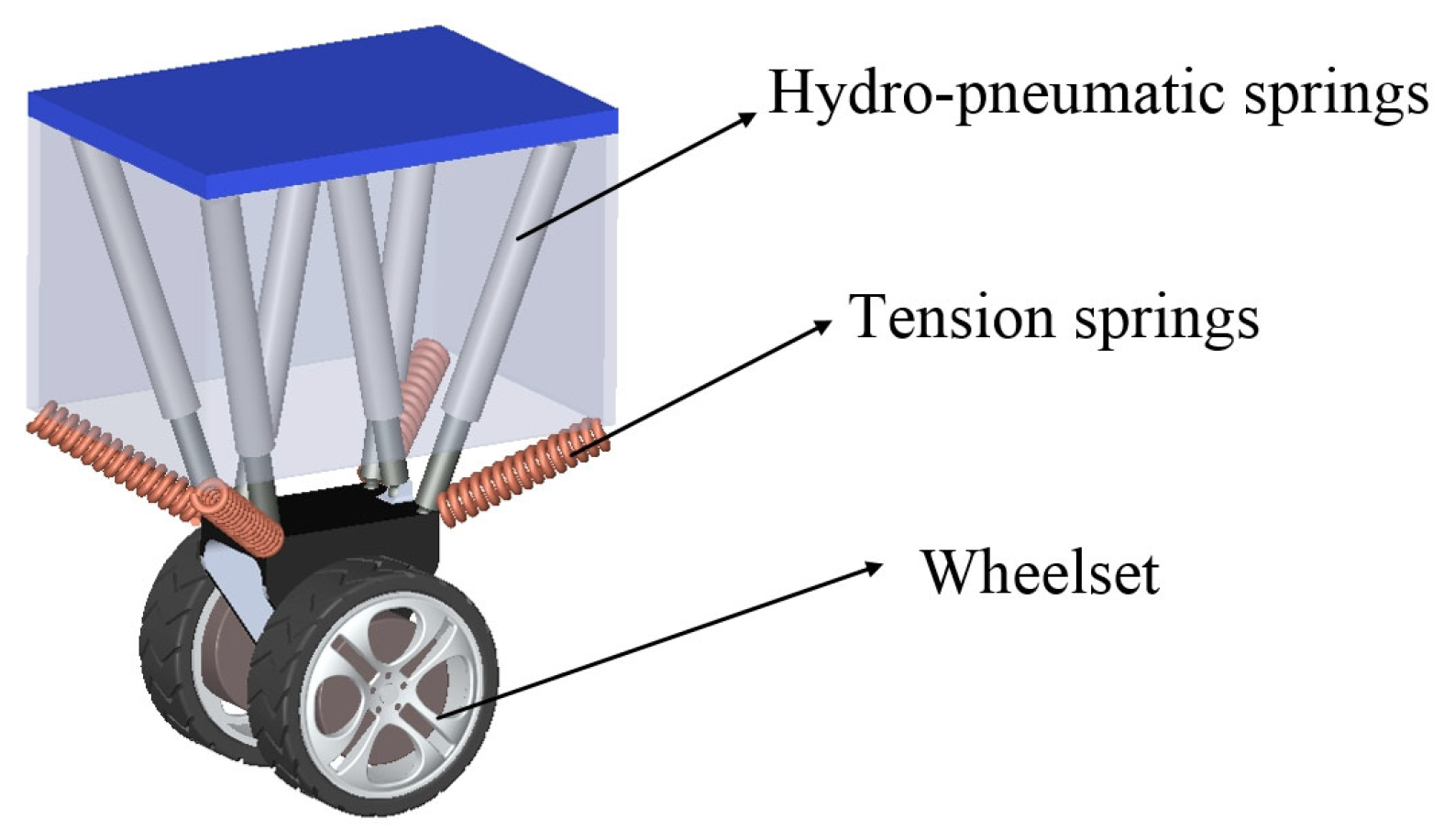
The dual in-wheel motor wheelset unit imposes new requirements on suspension design, and the suspension should have the characteristics of modularization [24]. It requires the suspension unit to withstand loads from all directions. Traditional suspensions only have the ability to withstand vertical loads, and longitudinal and lateral loads rely on the rigidity of the chassis or load-bearing body to resist impact. The suspension designed in this study includes six hydro-pneumatic springs and four tension springs. This six-degree-of-freedom suspension can bear loads from multiple directions, enhancing the maneuverability and flexibility of the wheelset unit. Under the action of tension springs, the suspension not only effectively mitigates the instability of differential steering but also equivalently reduces the unsprung mass, increasing the suspension response speed. In addition, tension springs assist in resisting lateral and longitudinal loads. The dual in-wheel motor wheelset and the six-arm hydro-pneumatic spring suspension together form the dual in-wheel motor wheel-leg system, as shown in Figure 2.

2.3. Functional Characteristics

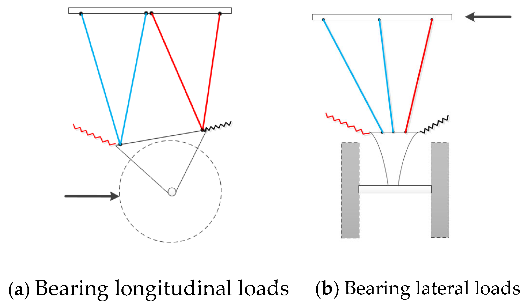
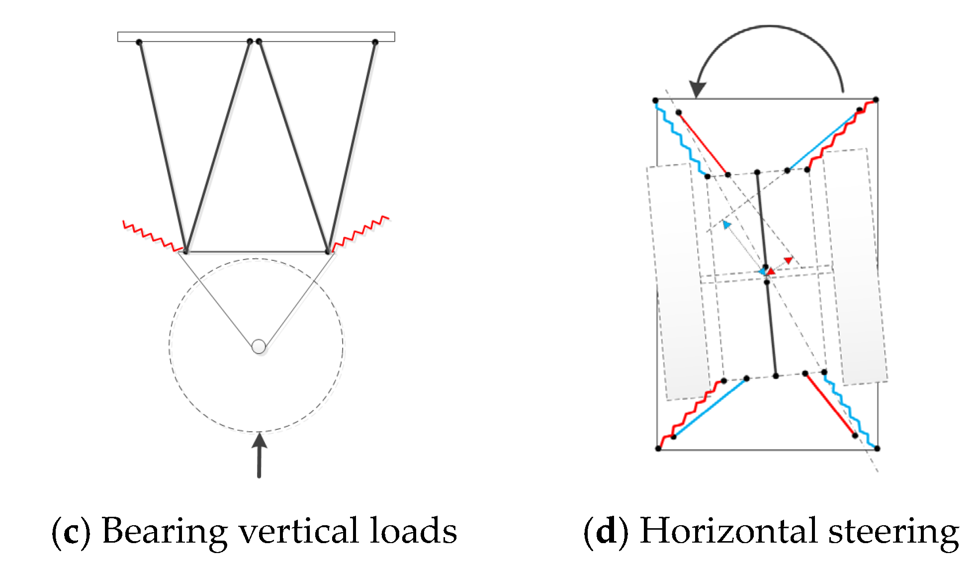
(1) Bearing longitudinal loads: During braking and acceleration, longitudinal loads are resisted by the corresponding hydro-pneumatic springs and tension springs. The impacts are dissipated through damping holes, as shown in Figure 3a. The blue line represents the extended state of the hydro-pneumatic spring, and the red line represents the compressed state of the hydro-pneumatic spring. The red wavy line represents the extended state of the tension spring, and the black/blue wavy line represents the compressed state of the tension spring.
(2) Bearing lateral loads: During turning and side-slipping, lateral loads are resisted by the corresponding hydro-pneumatic springs and tension springs. The impacts are dissipated through damping holes, as shown in Figure 3b.
(3) Bearing vertical loads: In the case of uneven road surfaces, vertical loads are quickly responded to by the hydro-pneumatic springs and tension springs, as shown in Figure 3c.
(4) Horizontal steering: During differential steering of the wheelset, the torque generated by the hydro-pneumatic springs is counteracted by the correction force of the tension springs, providing resistance to disturbance torques, as shown in Figure 3d.
According to the qualitative analysis above, the six-arm hydro-pneumatic spring suspension, aided by tension springs, can withstand loads from various directions. While tension springs offer the advantage of reducing the unsprung mass and improving the suspension response under vertical loads, the instability issues during steering require further quantitative study.

3. Theoretical Analysis of Hydro-Pneumatic Spring

3.1. External Single-Chamber Hydro-Pneumatic Springs

The proposed six-arm structure hydro-pneumatic suspension employs single-chamber hydro-pneumatic springs. Each spring is mainly composed of a hydraulic cylinder, a piston rod, a damping valve system, and an accumulator, as shown in Figure 4. This configuration is characterized by a simple structure and compact size [25]. When the piston rod moves upward, the piston pushes the hydraulic fluid from the cylinder through the damping valve system into the accumulator. Then, the inert gas in the accumulator chamber is compressed, increasing the elastic force of the hydro-pneumatic spring. This process is known as the compression stroke. As the fluid enters the accumulator, the pressure in the hydraulic cylinder decreases while the pressure in the gas chamber increases, causing the fluid to return from the accumulator to the hydraulic cylinder. When the fluid passes through the damping valve system, only the constant-flow damping holes are functional. The damping force during this process, which is known as the rebound stroke, exceeds that during the compression stroke.

3.2. Mathematical Derivation of Hydro-Pneumatic Spring

3.2.1. Force of Hydro-Pneumatic Spring

When the suspension is at the static equilibrium position, the force of the suspension equals the gravitational force of the sprung mass:
P S = m g ,
where P represents the equivalent pressure of the hydraulic fluid in the cylinder, S represents the equivalent area of the piston, and m represents the sprung mass.
Assuming that the displacement of the piston rod is x and the frictional force between the piston and the inner wall of the hydraulic cylinder is f, the force exerted by the hydro-pneumatic spring during suspension vibration is given as
F = P 1 S p f s i g n ( x ˙ ) ,
where P1 represents the pressure of the hydraulic fluid in the hydro-pneumatic spring cylinder, Sp represents the equivalent area of the hydro-pneumatic spring piston, and s i g n ( x ˙ ) is the sign function.

3.2.2. Mathematical Model of Damping Valve

During the operation of the hydro-pneumatic spring, the hydraulic fluid passes through the damping valve system. Assuming that the pressure of the fluid after passing through the damping valve system is P2, during the compression stroke, the fluid flows through the damping holes and the check valve. According to the thin-walled orifice theory [26], we have
P 2 P 1 = 1 2 ρ Q C d ( S c + S d ) 2 s i g n ( x ˙ ) .
During the rebound stroke, the fluid flows through the constant-flow damping holes without passing through the check damping holes, which is expressed as
P 2 P 1 = 1 2 ρ Q C d S c 2 s i g n ( x ˙ ) ,
where P1 represents the pressure of the fluid in the piston cylinder, P2 represents the pressure of the fluid after passing through the damping holes, ρ represents the density of the fluid, Cd is the flow coefficient of the constant-flow damping holes and check damping holes, Q represents the volume flow rate of the fluid, Sc represents the equivalent area of the constant-flow damping holes, Sd represents the equivalent area of the check damping holes, Sp represents the equivalent area of the piston, and x ˙ represents the relative velocity between the piston and the hydraulic cylinder.

3.2.3. Mathematical Model of Pipeline

After passing through the damping valve system, the hydraulic fluid enters the accumulator through the pipeline, where there is pressure loss. The pressure loss mainly depends on factors such as the internal diameter, length of the pipeline, and flow rate of the fluid. Assuming that the pressure of the fluid after passing through the pipeline is P3, according to the fluid flow theory for long slender pipelines [27], we have
P 3 P 2 = λ ρ l 2 D l x ˙ 2 s i g n ( x ˙ ) .
where λ represents the resistance coefficient along the path, l represents the length of the pipeline, and Dl represents the diameter of the pipeline. The calculation method for the resistance coefficient along the path λ is as follows [28]:
λ = 75 R e R e 2320 0.0025 R e 1 3 2320 < R e 4000 0.3164 R e 0.25 4000 < R e 10 5 0.0032 + 0.221 R e 0.237 10 5 < R e 10 6
where Re represents the Reynolds number, and its calculation formula is
R e = D l v μ
where v represents the average flow velocity of the oil in the pipeline, and μ represents the viscosity of the oil.

3.2.4. Mathematical Model of Accumulator

The gas used in the accumulator is nitrogen, which has physical properties similar to an ideal gas [29]. Therefore, the ideal gas state equation is used to simplify the model. Assuming that the hydro-pneumatic spring’s motion in the accumulator is adiabatic, we have
P g c V c γ = P 1 V 1 γ ,
where Pgc and P1 represent the initial and current gas pressures in the accumulator, respectively, and Vc and V1 represent the initial and current gas volumes in the accumulator, respectively.

3.2.5. Mathematical Model of Hydro-Pneumatic Spring

To simplify the mathematical model of the hydro-pneumatic spring, the following assumptions are made: (1) The effective sealing of all parts of the hydro-pneumatic spring is assumed, with no leakage in any components or connecting pipelines. (2) The hydraulic fluid inside the hydro-pneumatic spring is considered to be pure fluid, neglecting its compressibility. (3) Pressure losses along the length and local pressure losses in all components of the hydro-pneumatic spring are neglected. (4) The impact of temperature changes on the hydro-pneumatic spring during operation is neglected. (5) Owing to the excellent lubricating effect of the hydraulic fluid in the cylinder, frictional forces are extremely small, and their impact on the output force of the hydro-pneumatic spring is neglected.
According to the structure of the hydro-pneumatic spring, with the piston inner diameter denoted as D, the accumulator inner diameter denoted as d, the equivalent area of the piston denoted as Sp, the equivalent area of the accumulator denoted as Sg, and the initial height of the gas in the accumulator denoted as hc when the piston rod is displaced by x, the volume changes in the hydraulic cylinder and accumulator are equal. In this case, the floating piston displacement can be expressed as
Δ x = D 2 d 2 x .
From Equation (6), the following can be obtained:
P = P g c 1 ( 1 D 2 x d 2 h a ) γ .
From this, the elastic force Fk of the hydro-pneumatic spring can be expressed as
F k = P S g = P g c S g ( 1 D 2 x d 2 h a ) γ .
By taking the derivative of the elastic force Fk, the stiffness coefficient K of the hydro-pneumatic spring can be expressed as
K = d F k d x = D 2 P g c S g γ d 2 h c ( 1 D 2 x d 2 h a ) γ + 1 .
The damping force of the hydro-pneumatic spring generated by the hydraulic fluid passing through the constant-flow damping holes and the check damping holes in the damping valve system can be expressed as
F c = 1 2 ρ S p x ˙ S p C d ( S c + S d 1 + s i g n ( x ˙ ) 2 ) 2 s i g n ( x ˙ ) .
Thus, the damping of the hydro-pneumatic spring can be expressed as
C = d F c d x = S c 3 ρ x ˙ C d 2 S c + S d 1 + s i g n ( x ˙ ) 2 2 s i g n ( x ˙ ) .
The output force of the hydro-pneumatic spring, which is the resultant force of the elastic force and the damping force, can be expressed as
F = F k + F c .

3.3. Simulation and Analysis of Hydro-Pneumatic Springs

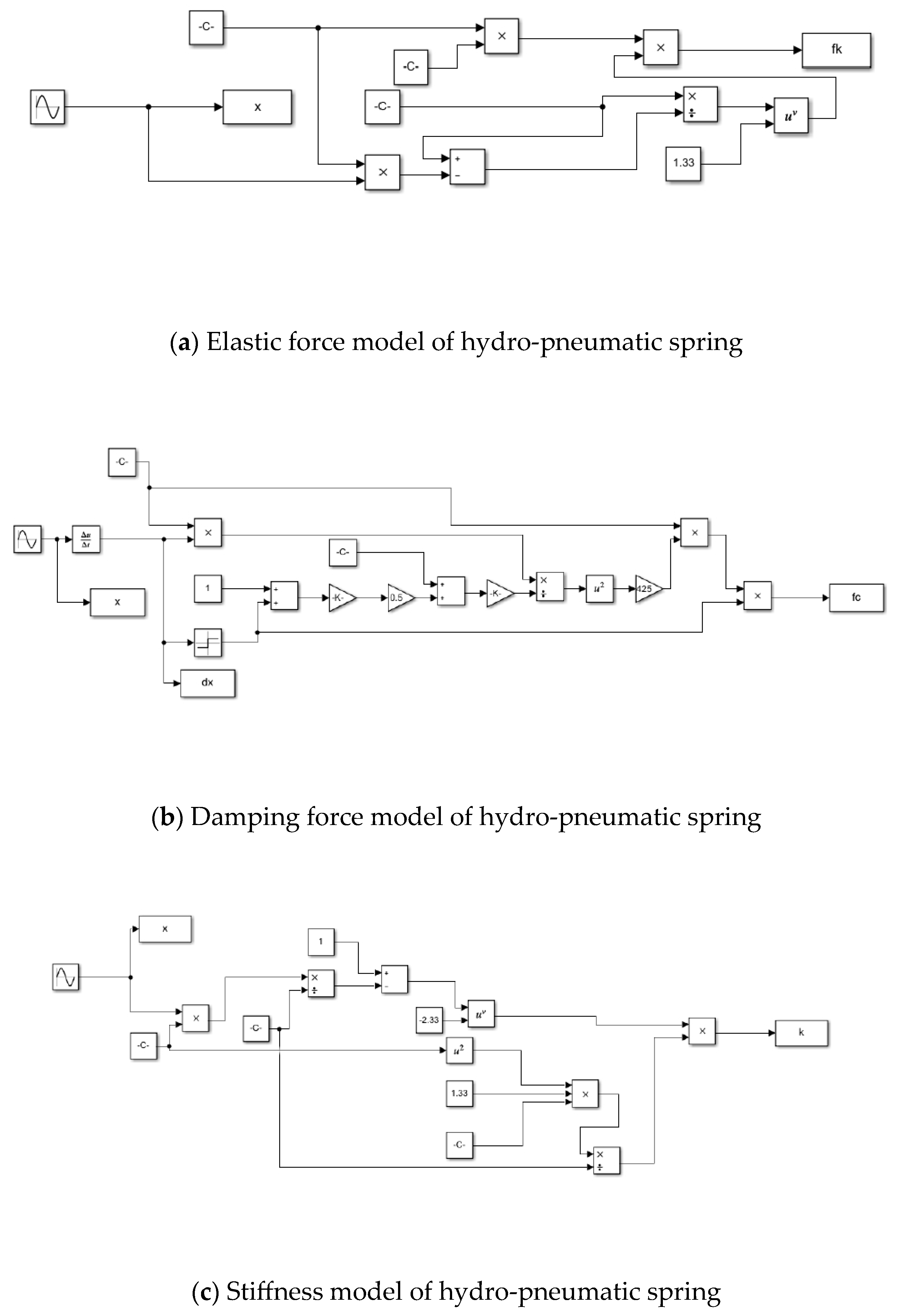
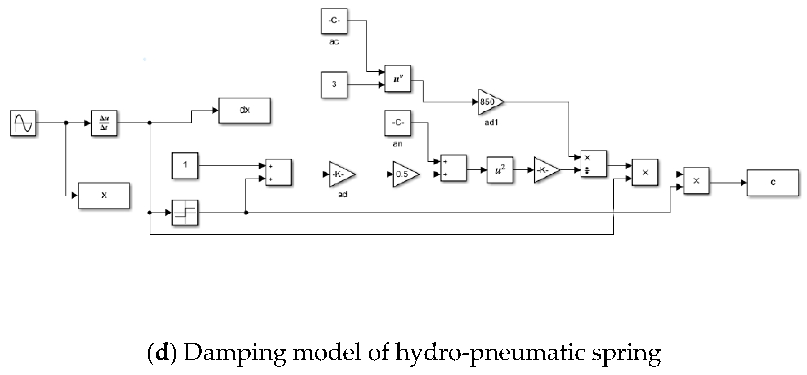
The specific parameters of hydro-pneumatic springs [30] are presented in Table 1. According to the above derivations and analyses, mathematical expressions for various important parameters of the hydro-pneumatic springs were obtained. The mathematical models of the hydro-pneumatic springs were built in MATLAB/Simulink R2018b (as shown in Figure 5) for simulation and analysis.
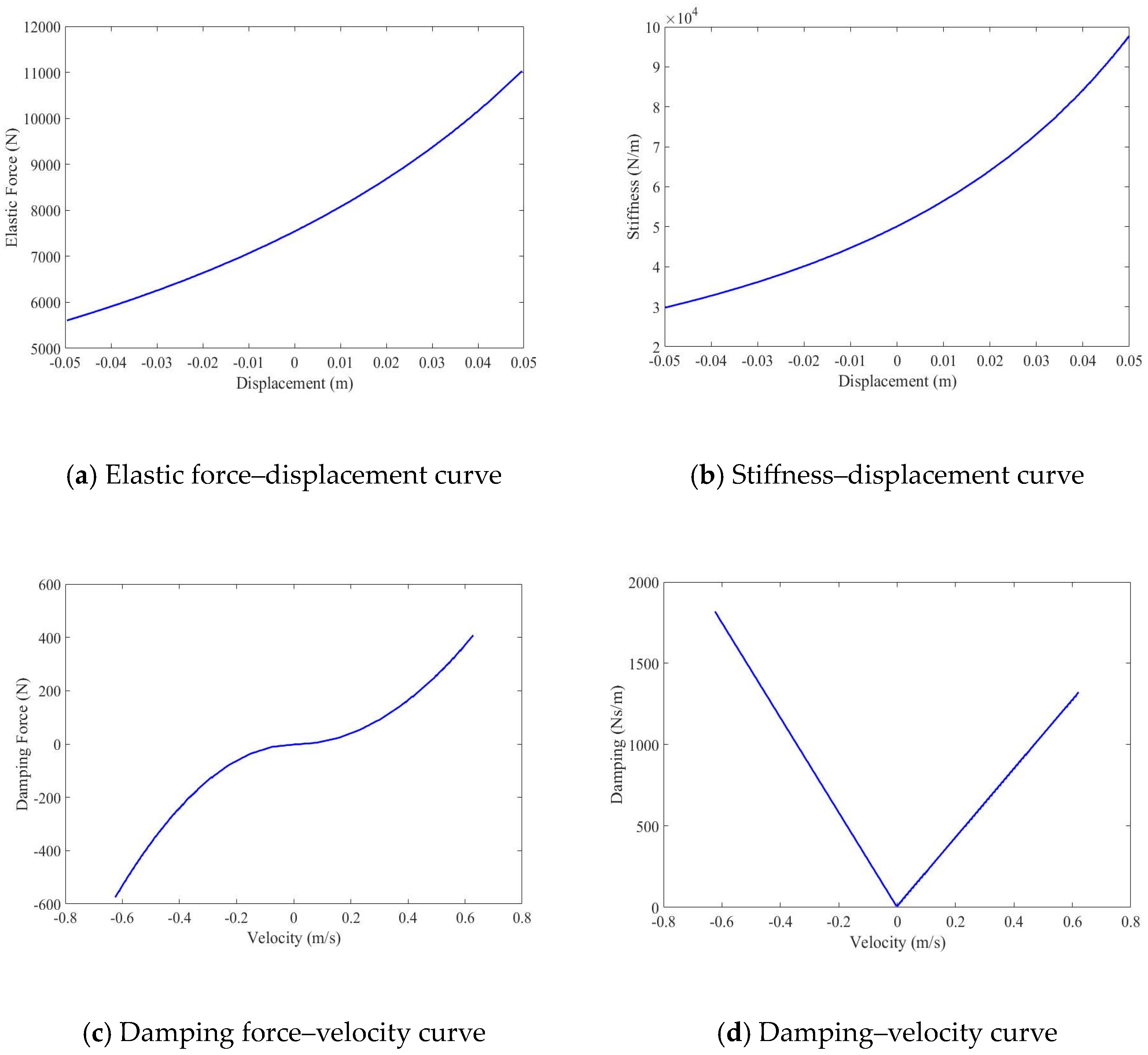
A sinusoidal excitation signal was used as the input excitation for the hydro-pneumatic spring’s stroke in the simulation, and the characteristic curves of the hydro-pneumatic spring were obtained, as shown in Figure 6. In Figure 6a,b, the elastic force and stiffness of the hydro-pneumatic spring exhibit significant nonlinear characteristics. As the piston was compressed continuously, the elastic force and stiffness of the hydro-pneumatic spring increased at an accelerating rate. The above phenomenon manifests in the suspension as follows: When the vehicle is driving on a smooth, flat road, the relative displacement of the piston rod of the hydro-pneumatic spring is small, resulting in a low stiffness. When the vehicle is driving on rough, uneven terrain, the relative displacement of the piston rod is large, leading to a sharp increase in stiffness [32]. The variable stiffness characteristics exhibited by the hydro-pneumatic spring under these two different road conditions ensure that the vehicle can maintain a high driving speed in a changing driving environment. They also demonstrate their significant advantages in regulating vehicle suspension systems. Figure 6c indicates that during the compression stroke, both the check damping holes and the constant-flow damping holes were functional. The damping coefficient of the hydro-pneumatic spring is relatively small, exhibiting a smaller damping force of the hydro-pneumatic spring. During the rebound stroke, the check damping holes closed, leaving only the constant-flow damping holes functional. At this point, the damping coefficient of the hydro-pneumatic spring was high. It indicates a strong damping force that attenuated oscillations and provided vibration damping and cushioning effects. In Figure 6d, it can be seen that the damping of the hydro-pneumatic spring varies linearly with speed. It increases with speed and undergoes a turning point at a speed of 0 m/s. Both the through hole and one-way hole of the compression stroke can pass oil, while the oil of the recovery stroke is only allowed to pass through the through hole. The slope of the damping of the pressure recovery stroke relative to the velocity change is greater than the slope of the compression stroke, which attenuates the oscillation generated during the operation of the hydro-pneumatic spring.
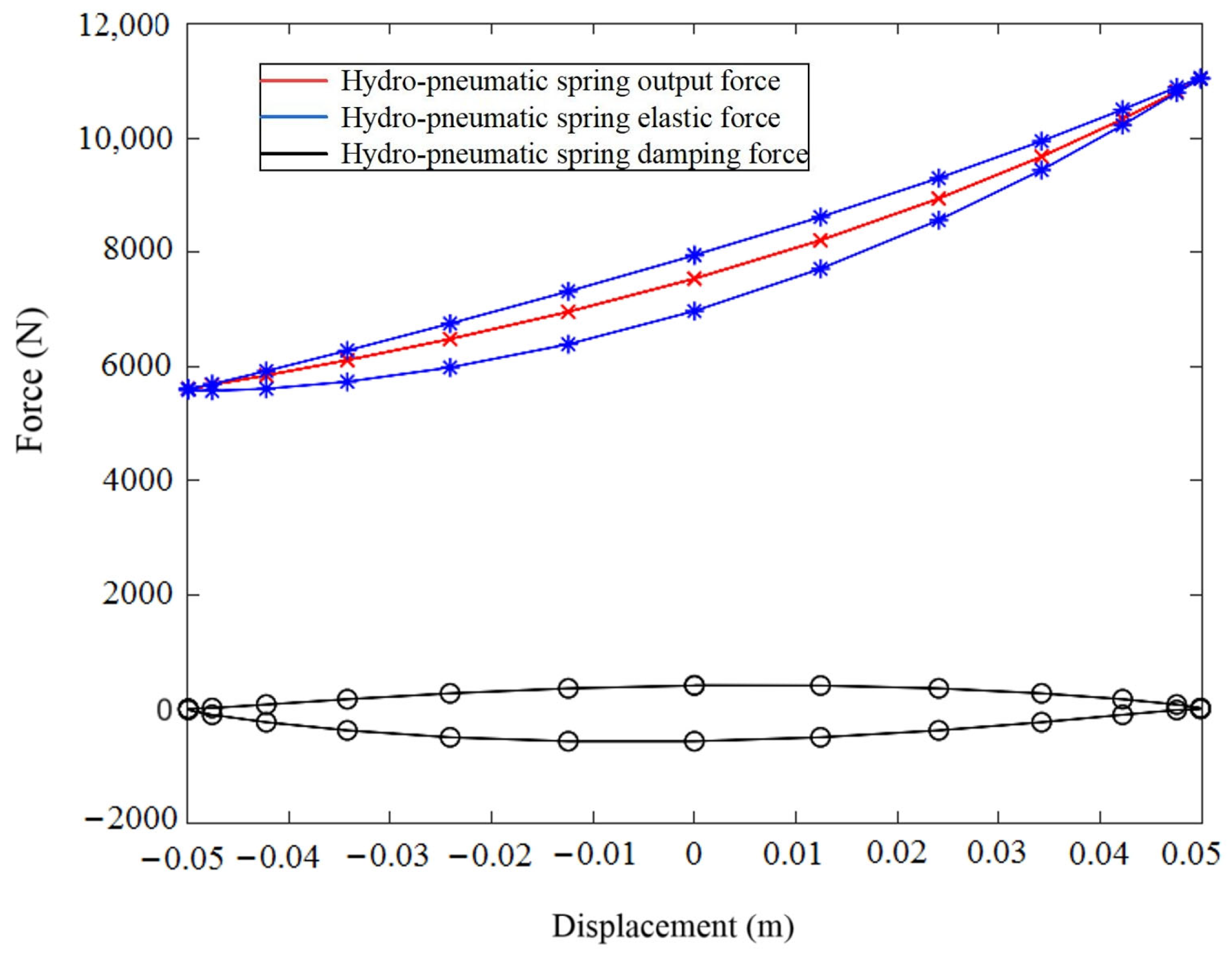
The output force of the hydro-pneumatic spring is the resultant force of the elastic force and the damping force, as shown in Figure 7. After the hydro-pneumatic spring moved for one cycle, the damping force curve formed a closed ellipsis. The area enclosed by the damping force curve represents the energy consumed by the hydro-pneumatic spring. Because the elastic force does not perform external work, the area enclosed by the output force curve of the hydro-pneumatic spring is equal to the area enclosed by the damping force curve. This nonlinear characteristic of the hydro-pneumatic spring ensures the ride comfort and operational stability of the vehicle.

4. Analysis of Horizontal Rotational Stability

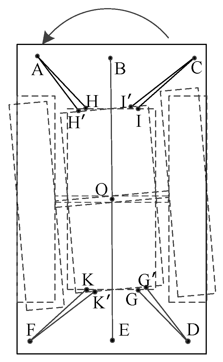
During the horizontal rotation of the six-arm structure hydro-pneumatic spring suspension, the degree of extension and contraction of the six-arm hydro-pneumatic spring varies. They generate rotational torque, which affects the stability of the suspension system. Thus, it is necessary to analyze the force conditions under the action of tension springs. Figure 8 illustrates the spring movement during the horizontal rotation of the suspension. Points A, B, C, D, E, and F denote the positions where the upper ends of the hydro-pneumatic springs connect to the vehicle body via ball joints. Points H, I, G, and K represent the positions where the lower ends connect to the wheelset via ball joints. Point O is the center of horizontal rotation. After rotation, H’, I’, G’, and K’ indicate the new positions of the ball joints at the lower ends of the hydro-pneumatic springs at the four corners.

4.1. Displacement Load Variation of Hydro-Pneumatic Springs

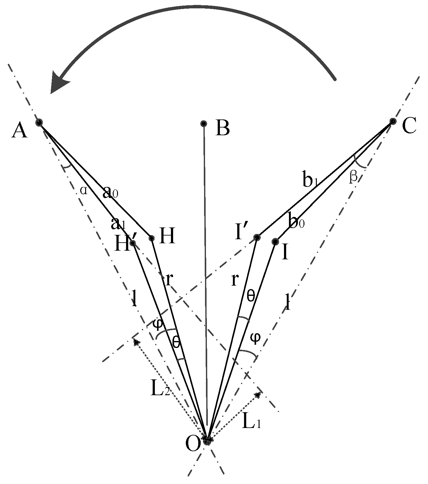
Assuming a counterclockwise direction is positive, it can be inferred from the structural characteristics of the suspension system that during horizontal rotation, the displacement loads of the hydro-pneumatic springs are symmetrically distributed about the upper and lower sections. Therefore, only the displacement load variations of the upper three hydro-pneumatic springs need to be analyzed. As shown in Figure 9, during rotation, the middle hydro-pneumatic spring (OB) does not generate rotational torque to affect the suspension stability. The two hydro-pneumatic springs on the left and right do generate such torque. Suppose that the wheelset rotates counterclockwise by an angle θ, where hc represents the vertical distance between the upper and lower ball joints of the hydro-pneumatic spring, s0 represents the initial length of the hydro-pneumatic spring, rc represents the distance from the lower ball joint to the center of rotation, and lc represents the horizontal projection distance from the upper ball joint to the center of rotation.

4.1.1. Displacement Load Variation of Left Hydro-Pneumatic Spring

At the static equilibrium position, the horizontal distance between the upper and lower ball joints of the left hydro-pneumatic spring is given as
a 0 = s 0 2 h c 2 .
The angle between the line connecting the lower ball joint and the center of rotation and the line connecting the upper ball joint and the center of rotation at the static equilibrium position is given as
φ = arcos l c 2 + r c 2 a 0 2 2 l c r c .
After rotation by an angle θ, the horizontal projection length of the hydro-pneumatic spring is given as
a 1 = l c 2 + r c 2 2 l c r c c o s φ θ .
Thus, the changed length of the hydro-pneumatic spring is given as
s 1 = a 1 2 + h c 2 .
The rotational lever arm corresponding to the left hydro-pneumatic spring is given as
α = arcos l c 2 + a 1 2 r c 2 2 l c a 1 L 1 = l c s i n α .
According to Equation (18), the load on the left hydro-pneumatic spring after rotation by an angle θ is given as
F 1 = P A 0 S A 1 s 0 s 1 D 2 h 0 d 2 n .
Thus, the unstable rotational torque provided by the left hydro-pneumatic spring is given as
N 1 = F 1 L 1 a 1 s 1 .

4.1.2. Displacement Load Variation of Right Hydro-Pneumatic Spring

At the static equilibrium position, the horizontal distance between the upper and lower ball joints of the right hydro-pneumatic spring is given as
b 0 = s 0 2 h c 2 .
The angle between the line connecting the lower ball joint and the center of rotation and the line connecting the upper ball joint and the center of rotation at the static equilibrium position is given as
φ = arcos l c 2 + r c 2 b 0 2 2 l c r c .
After rotation by an angle θ, the horizontal projection length of the hydro-pneumatic spring is given as
b 1 = l c 2 + r c 2 2 l c r c c o s φ + θ .
Thus, the changed length of the hydro-pneumatic spring is given as
s 2 = b 1 2 + h c 2 .
The rotational lever arm corresponding to the right hydro-pneumatic spring is given as
β = arcos l c 2 + b 1 2 r c 2 2 l c b 1 L 2 = l c sin β .
According to Equation (25), the load on the left hydro-pneumatic spring after rotation by an angle θ is expressed as
F 2 = P A 0 S A 1 s 0 s 2 D 2 h 0 d 2 n .
Thus, the unstable rotational torque provided by the left hydro-pneumatic spring is given as
N 2 = F 2 L 2 b 1 s 2 .
Summarizing the above equations, with the variation of the horizontal rotation angle θ, the unstable rotational torque is given as
N y = 2 N 1 + N 2 = 2 F 1 L 1 a 1 s 1 + F 2 L 2 b 1 s 2 = 2 L 1 P A 0 S A a 1 s 1 1 l c 2 + r c 2 2 l c r c c o s φ θ + h c 2 s 0 D 2 h 0 d 2 n + 2 L 2 P A 0 S A b 1 s 2 1 l c 2 + r c 2 2 l c r c c o s φ + θ + h c 2 s 0 D 2 h 0 d 2 n .
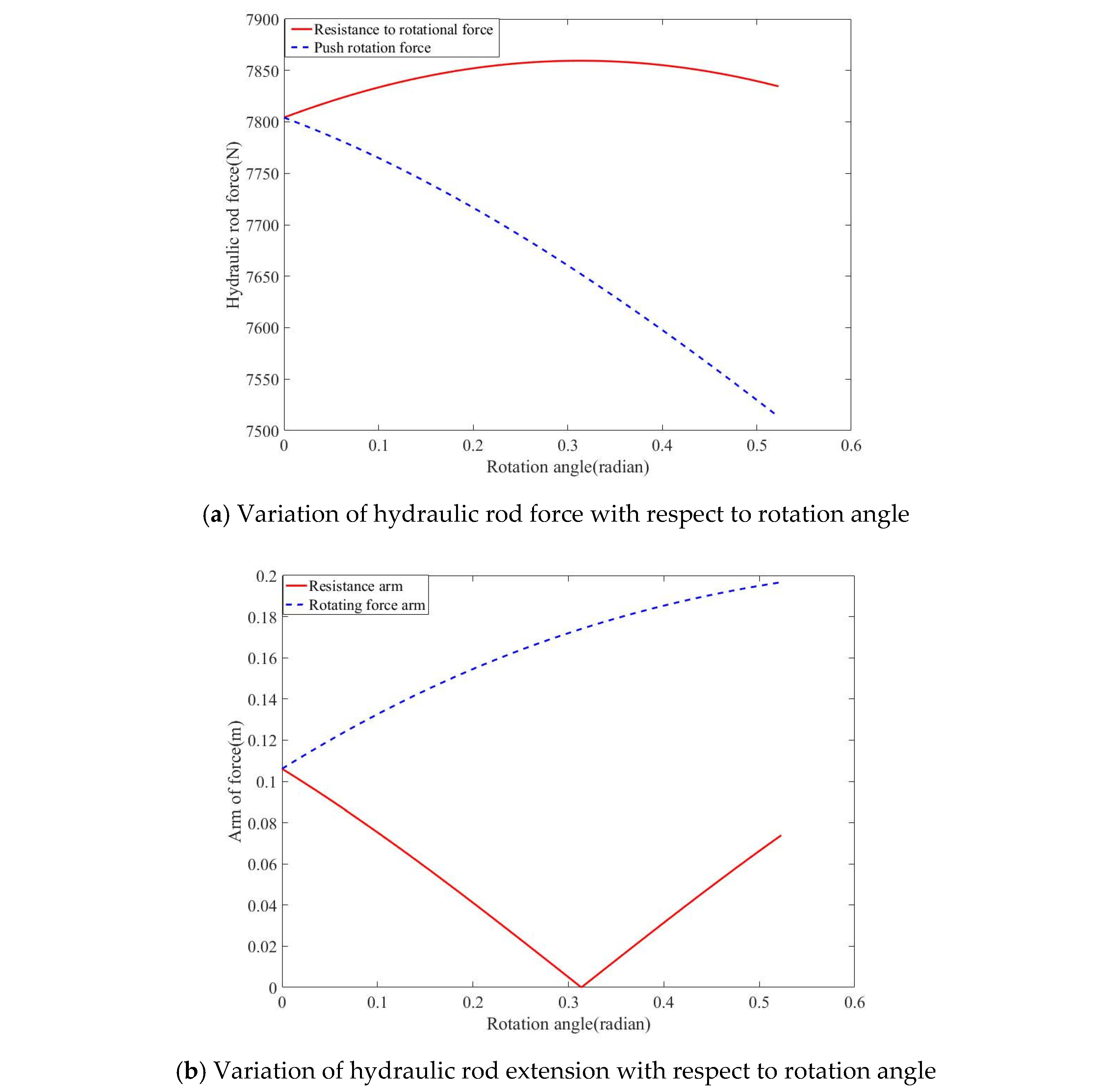
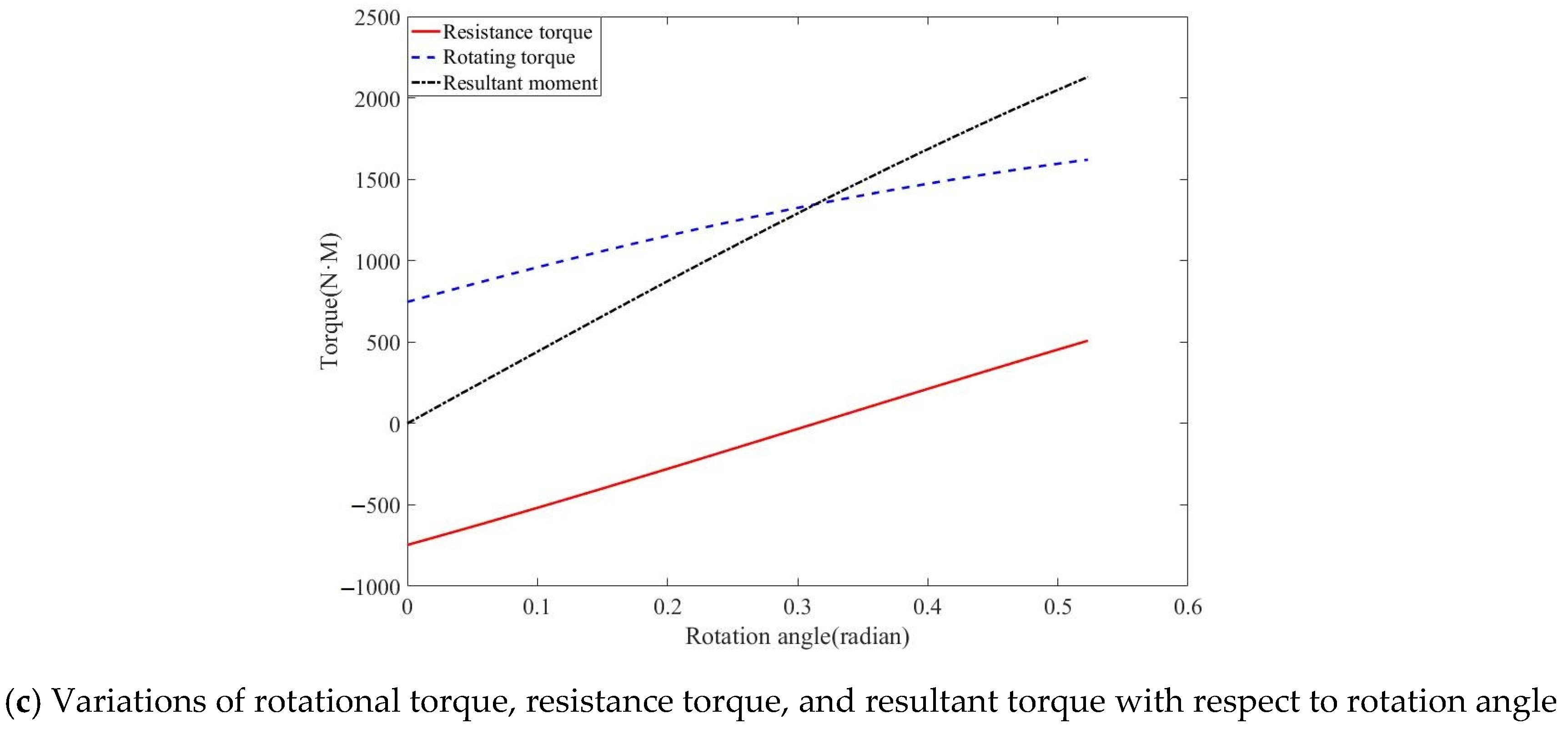
The initial parameters from Table 2 were input into the model, and the resulting curve of hydraulic rod force versus the rotation angle is shown in Figure 10a. The curve of the hydraulic rod extension versus the rotation angle is shown in Figure 10b. The curves of the rotational torque, resistance torque, and resultant torque versus the rotation angle are presented in Figure 10c.
As indicated in Figure 10, in the absence of the spring’s action, the hydro-pneumatic springs of the six-arm structure varied with horizontal rotation. After deviating from the initial position, during counterclockwise rotation, the rotational lever arm of the left hydro-pneumatic spring decreased but the elastic force increased more rapidly. This was due to the nonlinear stiffness characteristics of the hydro-pneumatic springs. Ultimately, within a certain range, there existed a resisting torque during counterclockwise rotation. It indicates that the six-arm hydro-pneumatic spring structure had a strong self-stabilizing property.

4.2. Analysis of Spring Correction Force

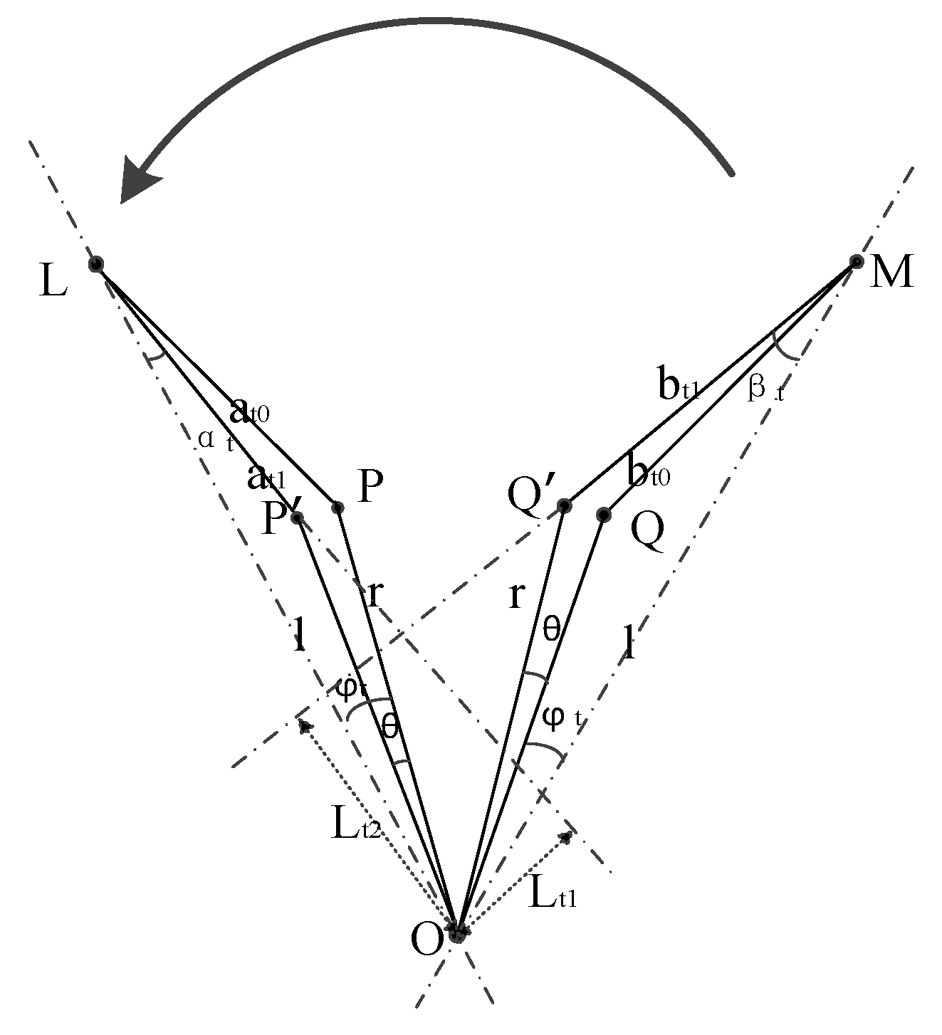
As shown in Figure 11, the fixed ends of the four tension springs are mounted below the vehicle body, perpendicular to the upper ball joints of the four hydro-pneumatic springs. The movable ends are attached to the fixed lower ball joints of the hydro-pneumatic springs. Therefore, the horizontal projection force analysis diagram of the springs is consistent with Figure 7. However, the initial length and vertical distance between the upper and lower ends of the springs differ from those of the hydro-pneumatic springs. The initial length of the springs is denoted as st, and the vertical distance between the upper and lower ends is denoted as ht.
The stiffness of the springs is calculated using the following formula:
k = G d 1 4 8 D 2 3 n 1 ,
where G represents the shear modulus of the spring material, d1 represents the wire diameter, D2 represents the mean diameter of the spring, and n1 represents the number of active coils.

4.2.1. Displacement and Tensile Force Variations of Left Tension Spring

At the static equilibrium position, the horizontal distance between the upper and lower fixed ends of the left tension spring is
a t 0 = s t 2 h t 2 .
The angle between the line connecting the lower fixed end of the tension spring to the center of rotation and the line connecting the upper fixed end to the center of rotation at the static equilibrium position is given as
φ t = arcos l c 2 + r c 2 a t 0 2 2 l c r c .
After rotation by an angle θ, the horizontal projection length of the tension spring is given as
a t 1 = l c 2 + r c 2 2 l c r c c o s φ θ .
The new length of the tension spring is given as
s t 1 = a t 1 2 + h t 2 .
The rotational lever arm corresponding to the left tension spring is given as
α t = arcos l c 2 + a t 1 2 r c 2 2 l c a t 1 L t 1 = l c sin α t
By combining the above equations, the tensile force of the left tension spring after rotation by an angle θ is expressed as
F t 1 = k s t s t 1 = k l c 2 + r c 2 2 l c r c c o s φ θ + h t 2 .
Thus, the unstable rotational torque provided by the left tension spring is given as
N t 1 = F t 1 L t 1 a t 1 s t 1 .

4.2.2. Displacement and Tensile Force Variations of Right Tension Spring

At the static equilibrium position, the horizontal distance between the upper and lower fixed ends of the right tension spring is given as
b t 0 = s t 2 h t 2 .
The angle between the line connecting the lower fixed end of the right tension spring to the center of rotation and the line connecting the upper fixed end to the center of rotation at the static equilibrium position is given as
φ t = arcos l c 2 + r c 2 b t 0 2 2 l c r c .
After rotation by an angle θ, the horizontal projection length of the right tension spring is
b t 1 = l c 2 + r c 2 2 l c r c cos φ + θ .
The new length of the right tension spring is given as
s t 2 = b t 1 2 + h t 2 .
The rotational lever arm corresponding to the right tension spring is given as
β t = arcos l c 2 + b t 1 2 r c 2 2 l c b t 1 L t 2 = l c sin β t .
By combining the above equations, the tensile force of the right tension spring after rotation by an angle θ is expressed as
F t 2 = k s t s t 2 = k l c 2 + r c 2 2 l c r c c o s φ + θ + h t 2 .
Thus, the corrective rotational torque provided by the right tension spring is given as
N t 2 = F t 2 L t 2 b t 1 s t 2 .
Summarizing the above equations, with the variation of the horizontal rotation angle θ, the spring correction torque is given as
N t = 2 N t 1 + N t 2 = 2 F t 1 L t 1 a t 1 s t 1 F t 2 L t 2 b t 1 s t 2 .

4.3. Analysis of Horizontal Rotational Torque of Wheelset

In the six-arm hydro-pneumatic spring suspension structure supplemented with tension springs, the final rotational torque acting on the wheelset is given as
N = N y + N t = 2 N 1 + N 2 + 2 N t 1 + N t 2 = 2 L 1 P A 0 S A a 1 s 1 1 l c 2 + r c 2 2 l c r c cos φ θ + h c 2 s 0 D 2 h 0 d 2 n + 2 L 2 P A 0 S A b 1 s 2 1 l c 2 + r c 2 2 l c r c cos φ + θ + h c 2 s 0 D 2 h 0 d 2 n + 2 k l c 2 + r c 2 2 l c r c c o s φ θ + h t 2 2 k l c 2 + r c 2 2 l c r c c o s φ + θ + h t 2
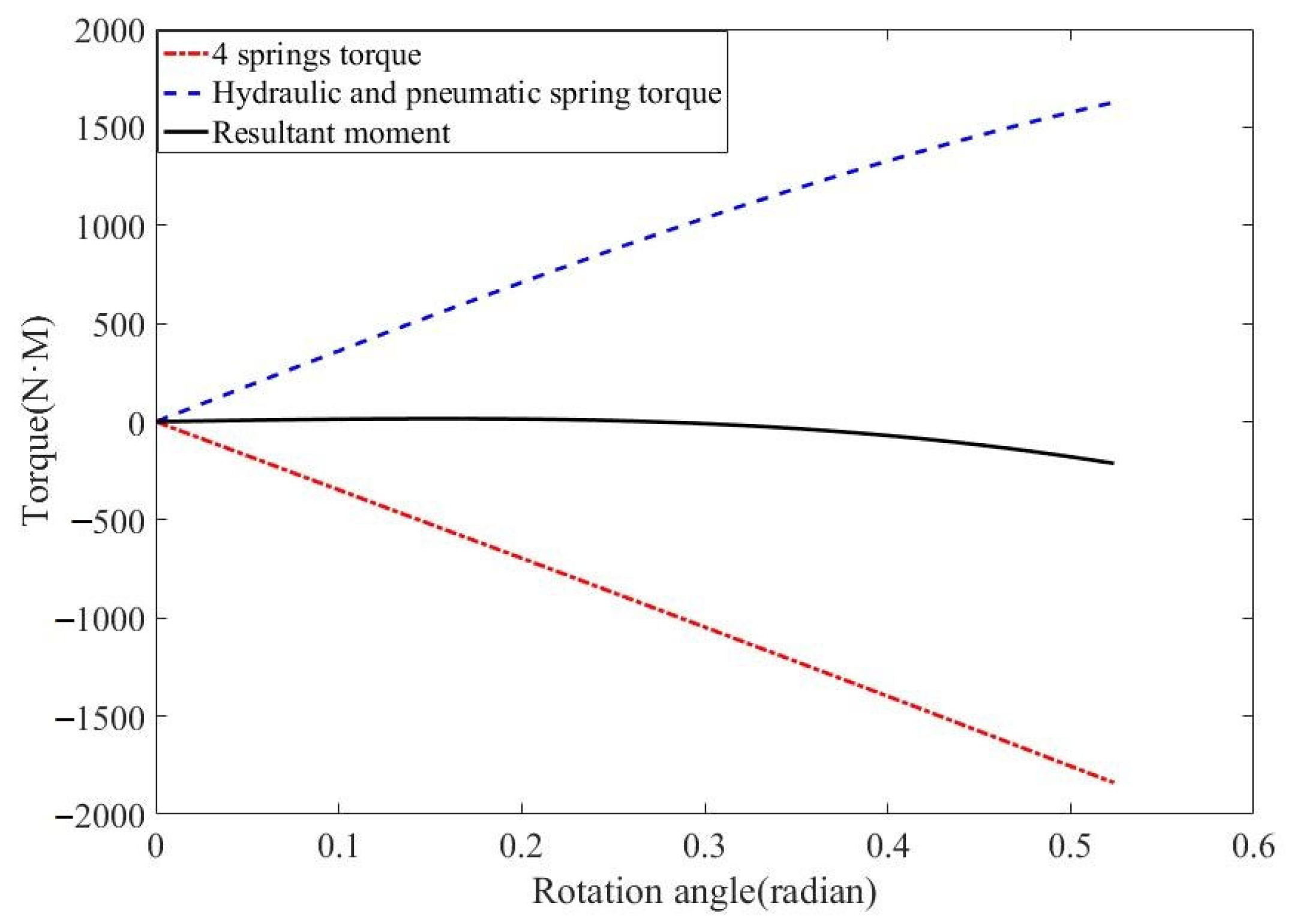
The parameters of the tension springs are presented in Table 3. By substituting these parameters into the model, the variations of the hydro-pneumatic springs’ rotational torque, tension resistance torque, and resultant torque with respect to the rotation angle were obtained, as shown in Figure 12. The results indicate that during the horizontal rotation of the six-arm hydro-pneumatic spring suspension, the hydro-pneumatic springs will generate rotational torque due to different degrees of expansion and contraction. However, under the action of the tension spring resisting torque, the resultant torque on the wheelset is basically maintained at 0 N·m.

4.4. Analysis of Spring Consistency and Stiffness Calibration

Manufacturing processes may introduce errors in the wire diameter, outer diameter, and material stress of the springs, leading to stiffness errors and inconsistency among multiple springs. Such inconsistency causes the correction performance of the six-arm wheelset suspension device to deviate from theoretical calculations. To minimize the inconsistency, an adjustment mechanism was designed at the spring and suspension interface for systematic calibration. In addition, the nonzero correction torque caused by the spring inconsistency was dynamically compensated by using the torque generated by the different frictional forces between the left and right wheels and the ground surface.
An adjustable mechanism was installed at the connection between the springs and the modular wheel-leg stator to fine-tune the initial length of the springs, aligning their stiffness as closely as possible with the theoretical values.
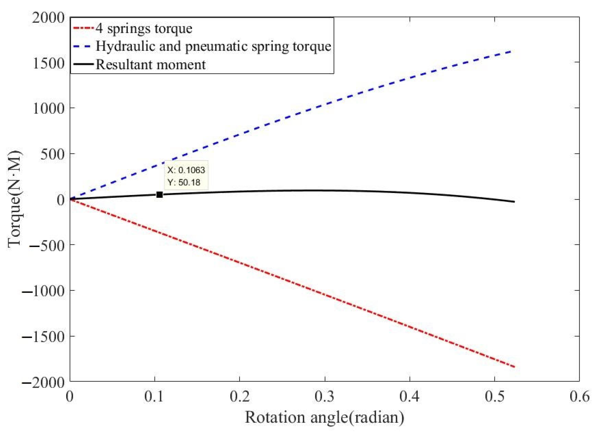
Using a spring stiffness error of ±5% as the maximum error for simulation calculations, when two sets of springs along the diagonal were set at +5% and –5%, the maximum correction torque error was determined. The simulation results are shown in Figure 13. With a spring stiffness error of ±5%, the spring correction torque generated a resistance/assistance rotational torque of approximately ±50 N·m. For the dual in-wheel motor wheelset drive mode, the dynamic adjustment of the left and right wheels can feasibly and practically compensate for torque errors smaller than 50 N·m.

5. Conclusions

Given the continuous development of new drive modes, a dual in-wheel motor wheel-leg drive mode is proposed. A six-arm suspension device based on hydro-pneumatic springs was designed for this drive mode. First, a static analysis was conducted, revealing that during wheelset steering (horizontal rotation), the suspension structure had strong self-stabilizing properties within a certain range, owing to the nonlinear stiffness characteristics of the hydro-pneumatic springs. However, the rotational lever arm of the hydro-pneumatic springs that promote rotation increased and the rotational lever arm of those that hinder rotation decreased. The load force of the hydro-pneumatic springs that impede rotation increased exponentially, which ultimately ensured stability. Finally, with the auxiliary action of tension springs, the rotational torque of the hydro-pneumatic springs and the tension resistance torque of the tension springs counterbalanced each other. The resultant moment of the wheelset unit is basically maintained at 0 N∙m. Considering the inconsistency issues in spring manufacturing, an adjustment mechanism was employed to calibrate the springs. The calibration kept the stiffness error within ±5%, yielding a maximum torque error of approximately 50 N·m. By relying on the dynamic adjustment of the wheelset differential, ideal stability and steering conditions can be achieved despite the spring inconsistency. The dual in-wheel motor wheel-leg drive unit designed in this article can be applied in the next generation of wheeled combat vehicles in the future. It will bring a brand new interior space layout scheme for vehicles.

Author Contributions

Conceptualization, Z.W. and B.J.; methodology, Z.W. and B.J.; software, C.S.; validation, C.S., Z.X. and Y.J.; formal analysis, B.J.; investigation, Z.W.; resources, H.Z.; data curation, C.S. and Z.X.; writing—original draft preparation, Z.W.; writing—review and editing, Z.W.; visualization, B.J.; supervision, Z.W.; project administration, H.Z.; funding acquisition, Z.W. All authors have read and agreed to the published version of the manuscript.

Funding

This research was funded by the Fund for Guiding the Transformation of Scientific and Technological Achievements of Shanxi Province, grant number 2021104021301061, by the Fund for Fundamental Research Program of Shanxi Province, grant number 202203021221106, and by the Research Fund of Shanxi Key Laboratory of High-end Equipment Reliability Technology, grant number 446110103.

Institutional Review Board Statement

Not applicable.

Informed Consent Statement

Not applicable.

Data Availability Statement

The data presented in this study are available on request from the corresponding author. The data are not publicly available due to privacy.

Conflicts of Interest

The authors declare no conflicts of interest.

References

  1. Chen, J. Automobile Construction; China Machine Press: Beijing, China, 2011. [Google Scholar]
  2. Wolfgang, B. Hydropneumatic Suspension Systems; Springer: Berlin/Heidelberg, Germany, 2022. [Google Scholar]
  3. Wu, Z.; Jiao, B.; Sun, C.; Zhang, Y.; Zhao, H. Design and Optimization of Hydropneumatic Suspension Simulation Test Bench with Electro-Hydraulic Proportional Control. Machines 2023, 11, 907. [Google Scholar] [CrossRef]
  4. Sohail, A.; Liu, C. Study on the vibration isolation characteristics of an anti-resonant hydropneumatic suspension. J. Eng. 2019, 13, 208–210. [Google Scholar] [CrossRef]
  5. Solomon, U.; Padmanabhan, C. Hydro-gas suspension system for a tracked vehicle: Modeling and analysis. J. Terramech. 2011, 48, 125–137. [Google Scholar] [CrossRef]
  6. Qin, B.; Zeng, R.; Li, X.; Yang, J. Design and performance analysis of the hydropneumatic suspension system for a novel road-rail vehicle. Appl. Sci. 2021, 11, 2221. [Google Scholar] [CrossRef]
  7. Zhang, Z.; Cao, S.; Ruan, C. Statistical linearization analysis of a hydropneumatic suspension system with nonlinearity. IEEE Access 2018, 6, 73760–73773. [Google Scholar] [CrossRef]
  8. Zhao, Z.; Gu, L.; Wu, J.; Zhang, X.; Yang, H. An Integrated Vibration Elimination System with Mechanical-Electrical-Magnetic Coupling Effects for In-Wheel-Motor-Driven Electric Vehicles. Electronics 2023, 12, 1117. [Google Scholar] [CrossRef]
  9. Shi, T. Suspension and Steering System Design and Performance Matching for In-wheel Motor Electric Vehicle. PhD Thesis, Jilin University, Jilin, China, 2015. [Google Scholar]
  10. Chen, L.; Dong, H.; Li, L. A new type suspension design suitable for an in-wheel motor driving syetem. J. Vib. Shock. 2015, 34, 174–180. [Google Scholar]
  11. Zhang, D.; Cao, Q.; Xu, L. Comparative Study on the Configuration of Two Wheel Motor Suspension Systems. Mach. Tool Hydraul. 2022, 50, 29–35. [Google Scholar]
  12. Cao, Q.; Xu, L.; Yi, X. Research on a Kind of Suspension Structure for In-wheel Motor and its performance of Vibration Suppression. Comput. Simul. 2021, 38, 94–98. [Google Scholar]
  13. Ma, Y.; Deng, Z.; Xie, D. Analysis and optimization of in-wheel motor suspension configuration. J. Cent. South Univ. (Sci. Technol.) 2014, 45, 3008–3014. [Google Scholar]
  14. Tan, D.; Lu, C. The Influence of the Magnetic Force Generated by the In-Wheel Motor on the Vertical and Lateral Coupling Dynamics of Electric Vehicles. IEEE Trans. Veh. Technol. 2015, 65, 4655–4668. [Google Scholar] [CrossRef]
  15. Yao, J.; Ding, S.; Li, Z.; Taheri, S.; Zhang, Z. Composite Control and Co-Simulation in In-Wheel Motor Electric Vehicle Suspension. Open Autom. Control. Syst. J. 2015, 7, 996–1001. [Google Scholar] [CrossRef]
  16. Li, Z.; Zheng, L.; Hu, Y.; Li, Y. Negative vibration effects of in-wheel motor electric vehicles and the method for suppressing them. J. Chongqing Univ. 2019, 42, 20–29. [Google Scholar]
  17. Wang, R.; Jing, H.; Yan, F.; Karimi, H.R.; Chen, N. Optimization and finite-frequency H control of active suspensions in in-wheelmotor driven electric ground vehicles. J. Frankl. Inst. 2015, 352, 468–484. [Google Scholar] [CrossRef]
  18. Li, Z.; Zheng, L.; Ren, Y.; Li, Y.; Xiong, Z. Multi-objective optimization of active suspension system in electric vehicle with in-wheel-motor against the negative electromechanical coupling effects. Mech. Syst. Signal Process. 2019, 116, 545–565. [Google Scholar] [CrossRef]
  19. Liang, R.; Yu, Z.; Ning, G. Restraint of negative effection vertical vibration of wheel rim driven motor vehicle based on shake absorption principle. J. Mach. Des. 2008, 25, 28–30. [Google Scholar]
  20. Wang, R.; Yu, F.; Shao, K.; Meng, X.; Ding, R.; Chen, L. Design and performance analysis of electromagnetic suspension based on in-wheel motor car. Trans. Chin. Soc. Agri-Cult. Mach. 2018, 49, 382–389. [Google Scholar]
  21. Han, Y.; Li, G.; Wang, Q.; Chen, T. Ride comfort of a new in-wheel motor driving electric vehicle based on the negative effect of vertical vibration. Sci. Technol. Eng. 2019, 19, 363–369. [Google Scholar]
  22. Zhao, Y.; Zhang, J.; Han, X. Design and study on the dynamic-damper mechanism for an in-wheel motor individual drive electric vehicle. Mech. Sci. Technol. Aerosp. Eng. 2008, 27, 395–398. [Google Scholar]
  23. Yang, D.; Jia, S.; Liang, D.; Feng, S. Coordinated Control Strategy Under Synchronous Condition of Permanent Magnet Brushless Hub Motor Wheelset System. Proc. CSEE 2024, 44, 2418–2428. [Google Scholar]
  24. Feng, W.; Wu, Z.; Jiao, B.; Ma, T. Analysis of six arm wheelset suspension based on hydro pneumatic spring. J. Ordnance Equip. Eng. 2022, 43, 260–267. [Google Scholar]
  25. Wang, H.; Jiang, C.; Liu, Q. Modeling and simulation analysis of working characteristics of single chamber hydro pneumatic spring. Comput. Simul. 2016, 33, 197–200+227. [Google Scholar]
  26. Zhang, D. A Study on Ride Comfort of Dump Truck’s Hydro-Pneumatic Suspension. Master’s Thesis, Jiangsu University, Zhenjiang, China, 2016. [Google Scholar]
  27. Cai, X.; Gu, Z.; Li, W.; Liang, X.; Peng, G. Hydro-pneumatic suspension parameters dynamical optimization design based on ride comfort. Mod. Manuf. Eng. 2011, 6, 53–57. [Google Scholar]
  28. Fan, B.; Mao, M.; Cai, W.; Chen, Y.; Du, F. Damping Characteristics Analysis of Hydro-Pneumatic Spring Damping Valve for Armored Vehicle. J. Ordnance Equip. Eng. 2021, 42, 1–7. [Google Scholar] [CrossRef]
  29. Wang, Y.; Wei, B.; Yang, Y. Establishment and verification of real gas polytropic index model for hydropneumatic suspension bladder accumulator. J. Agric. Eng. 2019, 35, 10–16. [Google Scholar]
  30. Wang, Y. Design, Simulation and Analysis of a Vehicle Hydro-Pneumatic Spring. Master’s Thesis, Changchun University of Science and Technology, Changchun, China, 2014. [Google Scholar]
  31. Wang, D. Determination of the Gas Polytropic Exponent in the Charge Proscess of the Energy Accumulator. Chin. Hydraul. Pneum. 2007, 9, 77–79. [Google Scholar]
  32. Feng, W. Design and Analysis of Wheel Set Suspension with Six-Arm Structure Based on Hydro Pneumatic Spring. Master’s Thesis, North University of China, Taiyuan, China, 2022. [Google Scholar]
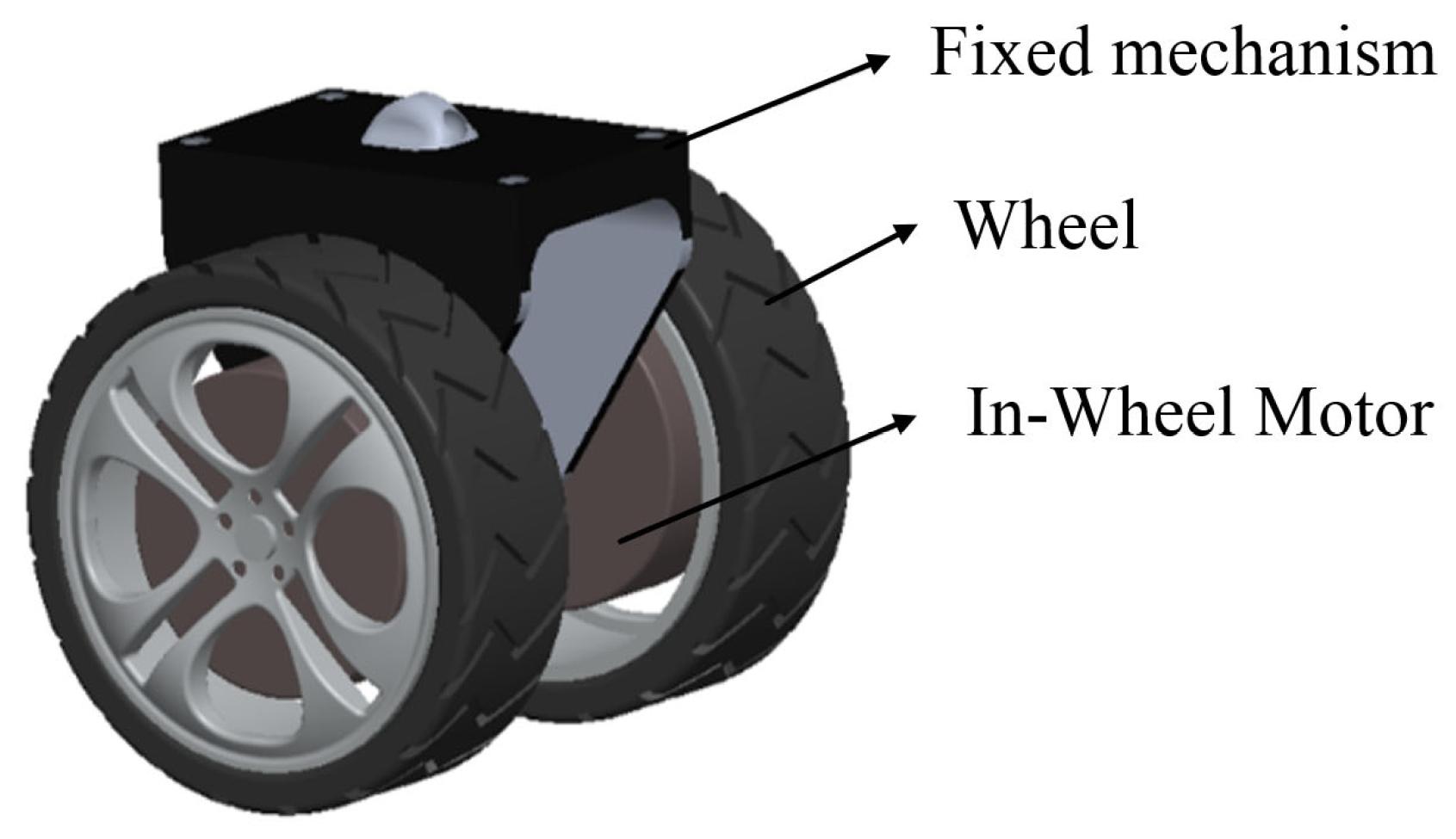
Figure 1. Dual in-wheel motor wheelset unit.
Applsci 14 09815 g001
Figure 2. Dual in-wheel motor wheel-leg system.
Applsci 14 09815 g002
Figure 3. Force analysis of the wheel-leg system under different load directions.
Applsci 14 09815 g003aApplsci 14 09815 g003b
Figure 4. Structure of the external single-chamber hydro-pneumatic spring.
Applsci 14 09815 g004
Figure 5. Simulation models of hydro-pneumatic springs.
Applsci 14 09815 g005aApplsci 14 09815 g005b
Figure 6. Characteristic curves of hydro-pneumatic springs.
Applsci 14 09815 g006
Figure 7. Output force curves of hydro-pneumatic springs.
Applsci 14 09815 g007
Figure 8. Schematic of horizontal rotation.
Applsci 14 09815 g008
Figure 9. Simplified model of horizontal rotation for the upper three hydro-pneumatic springs.
Applsci 14 09815 g009
Figure 10. Hydraulic rod force, displacement, and torque curves.
Applsci 14 09815 g010aApplsci 14 09815 g010b
Figure 11. Horizontal projection force analysis diagram of the springs.
Applsci 14 09815 g011
Figure 12. Variation curves of the hydro-pneumatic springs’ rotational torque, tension resistance torque, and resultant torque with respect to the rotation angle.
Applsci 14 09815 g012
Figure 13. Variation curves of torques with respect to the rotation angle under spring inconsistency.
Applsci 14 09815 g013
Table 1. Main parameters of the electro-hydraulic proportional hydraulic loading system.
NameValueNameValue
Hydraulic fluid density ρ/(kg/m3)850Diameter of check valve hole dd/(m)0.003
Initial pressure of gas in accumulator Pgc/(MPa)6Cross-sectional diameter of pipeline Dp/(m)0.012
Initial height of gas in accumulator ha/(m)0.2Pipeline length l/(m)0.2
Inner diameter of accumulator d/(m)0.04Flow coefficient Cd0.61
Inner diameter of piston D/(kg/m3)40Gas polytropic index γ [31]1.33
Diameter of damping hole dc/(m)0.005
Table 2. Initial suspension parameters.
NameValue
Initial length of hydro-pneumatic spring s0/mm800
Vertical distance between upper and lower ball joints of hydro-pneumatic spring hc/mm560
Distance from lower ball joint to rotation center rc/mm290
Horizontal projection distance from upper ball joint to rotation center lc/mm470
Table 3. Parameters of tension springs.
NameValue
Shear modulus of materials G/GPa79
Wire diameter d1/mm10
Mean diameter of the spring D2/mm54
Number of active coils30
Disclaimer/Publisher’s Note: The statements, opinions and data contained in all publications are solely those of the individual author(s) and contributor(s) and not of MDPI and/or the editor(s). MDPI and/or the editor(s) disclaim responsibility for any injury to people or property resulting from any ideas, methods, instructions or products referred to in the content.