Abstract
The investigation of new composite materials possessing low weight but not at the expense of their mechanical performance is of great interest in terms of reducing energy consumption in many industrial applications. This study is focused on the nanomechanical characterization of high-density polyethylene (HDPE)-based composite specimens modified with equal loadings of graphene nanoplatelets (GNPs) and/or multiwall carbon nanotubes (MWCNTs). Quasi-static nanoindentation analysis revealed the impact of the carbon nanofillers on the receiving of nanocomposites with higher nanohardness and reduced modulus of elasticity, reaching values of 0.146 GPa and 3.57 GPa, respectively. The role of the indentation size effect in elastic polymer matrix was assessed by applying three distinct peak forces. Nanoscratch experiments depicted the tribological behavior of the composite samples and inferred the influence of the carbon nanofillers on the values of the coefficient of friction (COF). It seems that the incorporation of 4 wt% GNPs in the polymer structure improves the scratch resistance of the material, resulting in a higher value of the exerted lateral force and therefore leading to the detection of a higher coefficient of friction at scratch of 0.401. A considerable pile-up response of the scratched polymer specimens was observed by means of in-situ SPM imaging of the tested surface sample area. The sway of the carbon nanoparticles on the composite pile-up behavior and the effect of the pile-up on the measured friction coefficients have been explored.
1. Introduction
Recently, the use of polymer-based nanocomposites in the research activities of the scientific community all over the world is widespread because of the common striving to produce a new class of high-quality multifunctional materials that would be able to replace the conventional ones [1]. High-density polyethylene (HDPE) is one of the promising semi-crystalline thermoplastic polymers in the field, standing out with its notable physical and mechanical properties [2,3,4,5]. Though some aspects of its nanomechanical characterization have already been referred [6], the detailed study of important nanosurface properties as indentation size effect, nanohardness, and reduced modulus of elasticity, as well as the nanoscratch behavior of HDPE-based composite materials, has yet to be done. The inclusion of inorganic nanofillers with high mechanical strength in thermoplastic polymer die has been investigated in terms of enhancement of the nanocomposite mechanical parameters by applying depth-sensing indentation technique [7] and, thereafter, an attempt to correlate the mechanical properties with the structural characterization of the composite material has been reported [8]. The resulting modified polymer samples have shown improved values of hardness and modulus of elasticity, but there has to be noted that these studies are constrained mainly over the quasi-static and dynamic nanoindentation behavior of HDPE-based specimens. Using a polyethylene matrix offers many advantages, such as low-cost processing and low energy consumption, that make it favorable for different applications, especially in electronic packaging [9] due to the matching of good mechanical and thermal properties [10,11]. In the last few years, graphene nanoplatelets and carbon nanotubes have rather barely been applied as carbon nanofillers in HDPE matrix in spite of their potentially positive effect on the nanocomposite mechanical, thermal, and electrical performance. However, Sahu et al. [6] have made a nanomechanical examination of carbon nanocomposite samples with hybrid structure based on HDPE and produced using the injection-molding method. Though the authors have picked a low level of nanofiller loading of 0.1 wt%, they established a significant increase of the hardness at the hybrid composite sample combining GNPs and nanodiamonds in the polymer die. In addition to the inclusion in nanocomposite systems, HDPE has also been subjected to nanomechanical testing as a part of incompatible polymer blends [12]. As outcome, there has been suggested a correlation between the interfacial and mechanical properties of the polymer mixture. The sophisticated hierarchical structure of high-density polyethylene, consisting of both crystalline and amorphous phases [13], has an impact on its nanomechanical surface behavior that could be modified in positive sense by adding carbon nanoparticles as reinforcement. Rez et al. [14] observed an increment in nanohardness and elastic modulus of about 10% as a result of the addition of MWCNTs in HDPE die. In general, up to now, the nanoindentation research on HDPE-based materials has been predominantly centered on nanocomposites incorporated with carbon nanotubes [15] or nitride types of nanofillers [7,16], and to find a study dealing with a hybrid carbon structure in a polyethylene matrix is rather a rareness.
In the present article, it was made an attempt to explore the elastic–plastic response of polymer nanocomposite samples by applying a quasi-static nanoindentation method with setting of three separate peak forces in the trapezoid load function. For achieve a better understanding of the wear properties of the new material, it was performed an experimental approach consisting of estimation of COF through nanoscratch testing of the specimens’ surface. Assessment of the pile-up formed by the lateral displacement of the indenter disclosed the impact of the carbon nanofillers on the mechanical behavior of the composite materials. Thermal and electrical measurements have been added to shape more complete characterization of the nanocomposite properties.
2. Materials and Methods
2.1. Materials
The output polymer material—HDPE N100-20—was purchased as a powder from Rowalit, Switzerland. According to the manufacturer, the polymer density is 0.956 g/cm3, and the thickness of the polymer particles has to be up to 80 μm. MWCNTs (NC7000) were bought from Nanocyl, Belgium, while TNGNPs (Graphene Nanoplatelets, TimesNano, Chengdu, China) were provided by TimesNano, China. The technical characteristics of the carbon nanofillers are presented in Table 1.
2.2. Preparation of Nanocomposite Specimens
Novel innovative approach was applied in the manufacturing of the HDPE-based nanocomposite materials. First step in preparing of new nanocomposites was the use of a wrapping method with respect to the polymer particles by mixing them with the carbon nanofiller in a ball mill for two hours at a spin velocity of 70 turnovers/min. The polymer powder and the carbon nanoparticles were dried in advance in a vacuum dryer at 80 °C for 4 h in order to remove the adsorbed humidity from the output materials and allow better polymer–nanofiller interaction during the wrapping process. That way there have been obtained two masterbatches in shape of powder having 4 wt% GNPs and 4 wt% MWCNTs, respectively, in a HDPE matrix. As a second step in the production setup, the monofiller composite materials were subjected to melt blending in the barrel of a corotational twin screw extruder (Thermo Scientific, Waltham, MA, USA) that enabled the production of homogeneous nanocomposites as filaments. Additionally, a hybrid bifiller composition comprising 2 wt% GNPs and 2 wt% MWCNTs incorporated in HDPE die was produced by using the already-prepared monofiller compounds. The extrusion processing of the three nanocomposites was conducted in eight temperature zones by setting the screw speed in a manner allowing to acquire a filament with a diameter of 1.75 mm that could be employed for future 3D-printing applications. All nanomechanical experiments were performed over a flat surface of hot-pressed at 160 °C round shaped samples with a thickness of ~2 mm and a diameter of 25 mm. Two monofiller concentrations of 4 wt% GNPs and MWCNTs incorporated in a HDPE matrix and one bifiller hybrid composition consisting of 2 wt% GNPs and 2 wt% MWCNTs in a polymer die were selected for nanomechanical, thermal, and electrical investigations including the neat HDPE taken as a reference.

Table 1.
Technical data of the employed carbon nanomaterials.
Table 1.
Technical data of the employed carbon nanomaterials.
| Carbon Nanofiller | Diameter | Length | Purity | Aspect Ratio | Average Thickness | Specific Surface Area (SSA) | Volume Resistivity |
|---|---|---|---|---|---|---|---|
| MWCNTs (NC7000) | 9.5 nm (OD) | 1.5 μm | 90% | 150 | − | 250–300 m2/g | 10−4 Ω.cm |
| TNGNPs | 5−10 μm | − | 99.5% | 500 | 4–20 nm | − | 4 × 10⁻⁴ Ω.cm |
2.3. Instrumental Methods
Quasi-static nanoindentation and nanoscratch measurements were perpetrated on Hysitron TI 980 instrument (Bruker, Billerica, MN, USA) by using a 2D transducer assembly (both normal and lateral force) equipped with a Berkovich probe. A typical radius of curvature for a standard Berkovich indenter would be approximately 150 nm. Three distinct maximum loads of 100 μN, 1000 μN, and 10,000 μN were selected in the nanoindentation study of the composite samples seeking to confirm the conjecture of presence of indentation size effect as a function of the elastic deformation and indentation depth [17,18]. The viscoelastic polymer nature of the materials required to add a hold segment in the setting of trapezoid load function and to establish a loading and an unloading rate of 200 μN/s. The load was maintained for 2 s in the hold segment at every indentation peak force aiming to reduce the creep effect. Nanoscratch experiments were carried out at constant load scratch function consisting of nine segments by applying peak force of 1000 μN and total scratch length of 10 μm. The coefficient of friction was extracted from the segment of interest, where the peak load is being kept constant for 15 s, matching with the substantial move of the probe into the composite surface, as already reported in a previous paper on nanomechanical characterization of polymer surfaces [19]. A test procedure of tip-to-optic calibration helping to select an experimental area with satisfactory surface roughness was performed prior to every one single nanoscratch. Evaluation of both the average surface roughness and the residual side pile-up formed past a groove has been made by analysis of in-situ SPM image of nanoscratched sample surface area using the TriboView 5.9 instrumental software.
The thermal conductivity of the composites was measured by using an LFA 467 HyperFlash (Netzsch, Selb, Germany). The samples were prepared by pressing them into a mold with a diameter of 25 mm and a thickness of 2 mm. Using thermal diffusivity values (α), density (ρ), and specific heat capacity (Cp), the thermal conductivity (λ) values were calculated according to the following Equation (1):
λ = α·ρ·Cp.
LFA and the reference sample were used to determine the specific heat capacity. In order to evaluate the influence of temperature on the thermal conductivity of the composites, the measurements were carried out at the following temperatures: 25, 50, and 75 degrees.
A thermal imaging camera (TIM106S, Micro–Epsilon, Ortenburg, Germany) was used to monitor the temperature of the specimens during the electrical measurements. A hotplate stirrer was employed to heat the samples. The temperature was increased from 20 °C to 100 °C with a step of 10 °C. For value validation purposes, every measurement was repeated at least three times. The electrical resistance was determined by an oscilloscope (LCR Bridge HM8118, HAMEG Instruments, Mainhausen, Germany) with 0.5 s of acquisition time for 5 min.
The morphology of the HDPE-based nanocomposites was observed by a scanning electron microscope (SEM, SH 4000M, Hirox, Oradell, NJ, USA). Hot-pressed samples were first immersed in liquid nitrogen, then cut to uncover the inner layers of the cross-section surface, and finally coated with gold (layer thickness: ~200 Å) using a sputter coater (Q150RS plus, Quorum, Washington, DC, USA) to make them conductive. To receive better imaging of the nanofiller dispersion in the HDPE matrix, a chemical etching procedure was conducted as an alternative sample preparation method prior to SEM analysis. It consisted of sinking the specimens in a solution of 2 wt% potassium permanganate (KMnO4) dissolved in a 1:1 v/v of H3PO4:H2SO4 for a definite period of 5 h [20].
3. Results and Discussion
3.1. Quasi-Static Nanoindentation
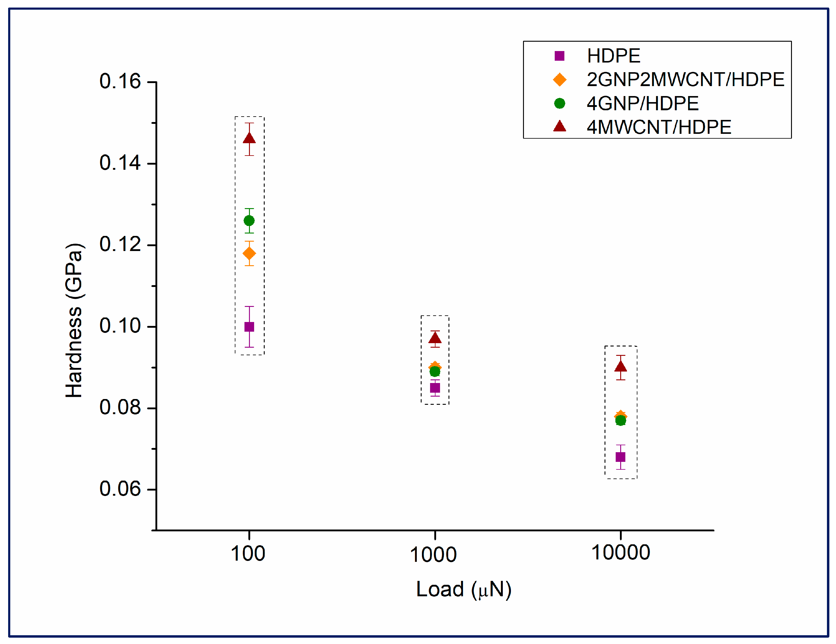
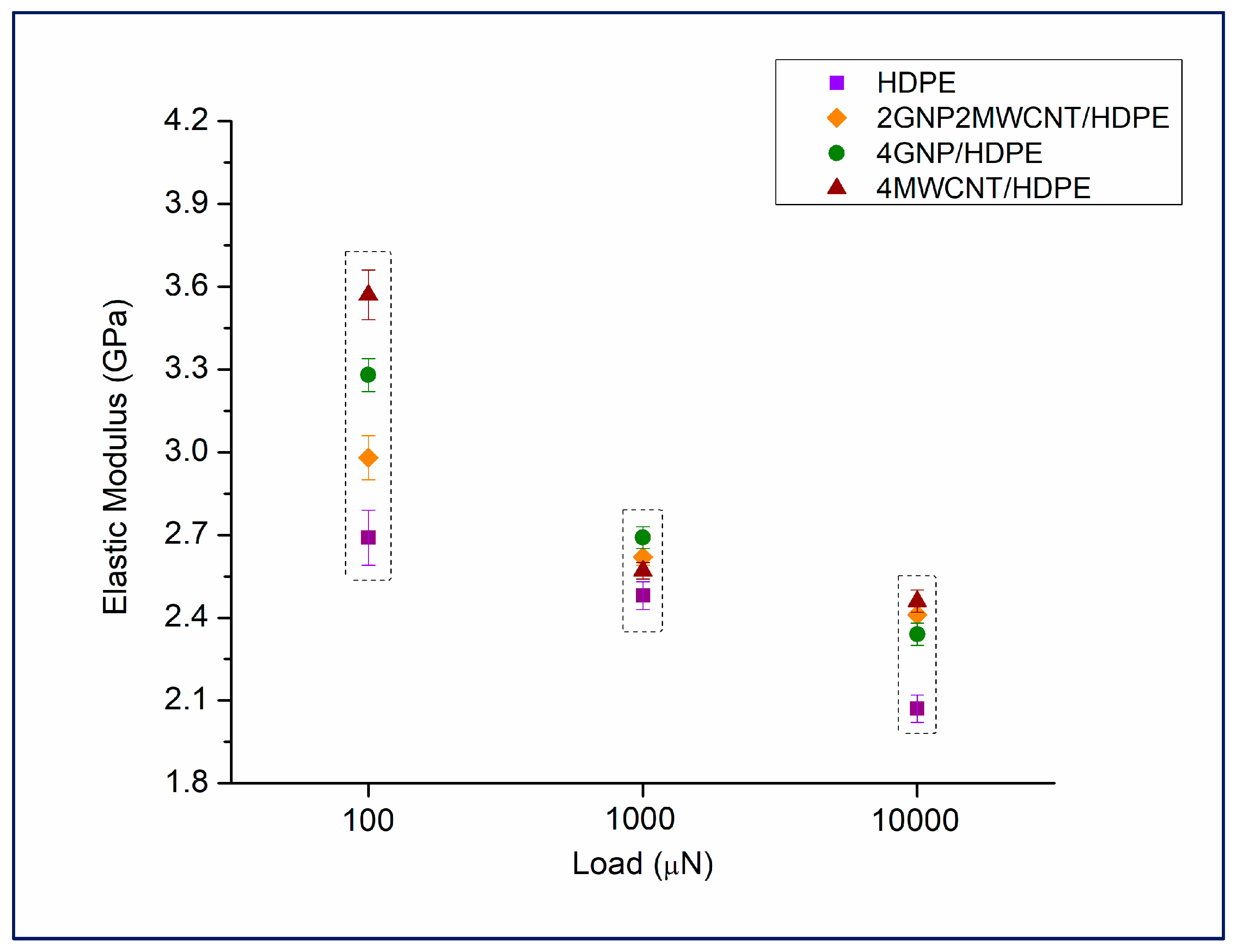
The mathematical calculations of the received experimental data were performed by the aid of the instrumental software as their essence rests on the analysis of the unloading part of the indentation load vs. indentation depth curve by using the Oliver and Pharr method [21], thoroughly depicted in a preceding article [22]. The nanoindentation experiments have shown better mechanical properties as nanohardness and reduced modulus of elasticity of the composite samples compared to the pure HDPE, regardless of the exerted peak load (see Figure 1 and Figure 2). Each one symbol in the figures is a mean value corresponding to successful completion of at least 49 indentations laid down in the experimental grid. The standard deviation of the measured parameters has been added in the graph, though the presented average values are based on indentation curves picked up from optically selected surface areas with high flatness, as confirmed by the in-situ SPM imaging (see Figure 3). Moreover, the estimation of the test data was made after careful removal of the wrong nanoindentation curves impeding the precise formulation of the results. No matter of the applied peak force, the composite filled with MWCNTs demonstrated best nanohardness, while the values of the neat HDPE were at the bottom. These results suggest good dispersion of the carbon nanotubes in the polymer matrix, leading to improved mechanical behavior. Similar finding has been reported in another article dealing with HDPE-based materials reinforced with a relatively low content of carbon nanofillers [6]. A glance into the dependence of nanocomposite mechanical parameters on the indentation load, plotted in Figure 1 and Figure 2, prompts for a presence of size effects that become more noticeable when going deeper in the polymer material [23] reaching to the elastic zone, where these effects, being elastic in nature, are mostly set down by the complex molecular structure of the semi-crystalline polyethylene matrix [24].
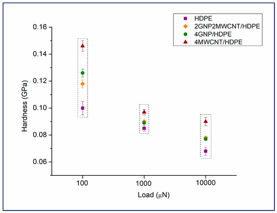
Figure 1.
Nanohardness of the nanocomposite samples, including pure HDPE as a reference, measured at three different peak loads—100 μN, 1000 μN, and 10,000 μN.
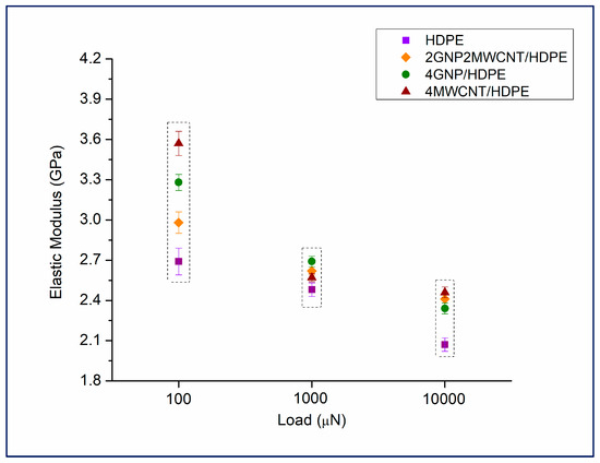
Figure 2.
Reduced modulus of elasticity of the nanocomposite samples, including pure HDPE as a reference, measured at three different peak loads—100 μN, 1000 μN, and 10,000 μN.
As expected, an increase in contact depth with increment of the applied indentation force was observed as regards all tested nanocomposite samples (Table 2). Except the fact that the penetration of the probe is higher in the pure HDPE at every exerted maximum load, the impact of the carbon nanofillers on the composites’ mechanical response is more distinguishable when the peak force is set to 100 μN by receiving values that are more sensible to the plastic behavior of the materials coming from the top layer of the samples. The effect of the hybrid nanocomposite structure on the determined mechanical parameters is more visible at peak loads of 1000 μN and 10,000 μN, though in most of the experimental data, the bifiller composition has fainter nanomechanical behavior than the polymer composite filled with 4 wt% MWCNTs. This could be due to several factors as worst nanoparticles distribution in the specimen 2wt%GNP2wt%MWCNT/HDPE and the superior role of carbon nanotubes with respect to the input of higher hardness in the composite matrix [25].

Table 2.
Average contact depth in the nanocomposite surface as a function of nanoindentation peak load.
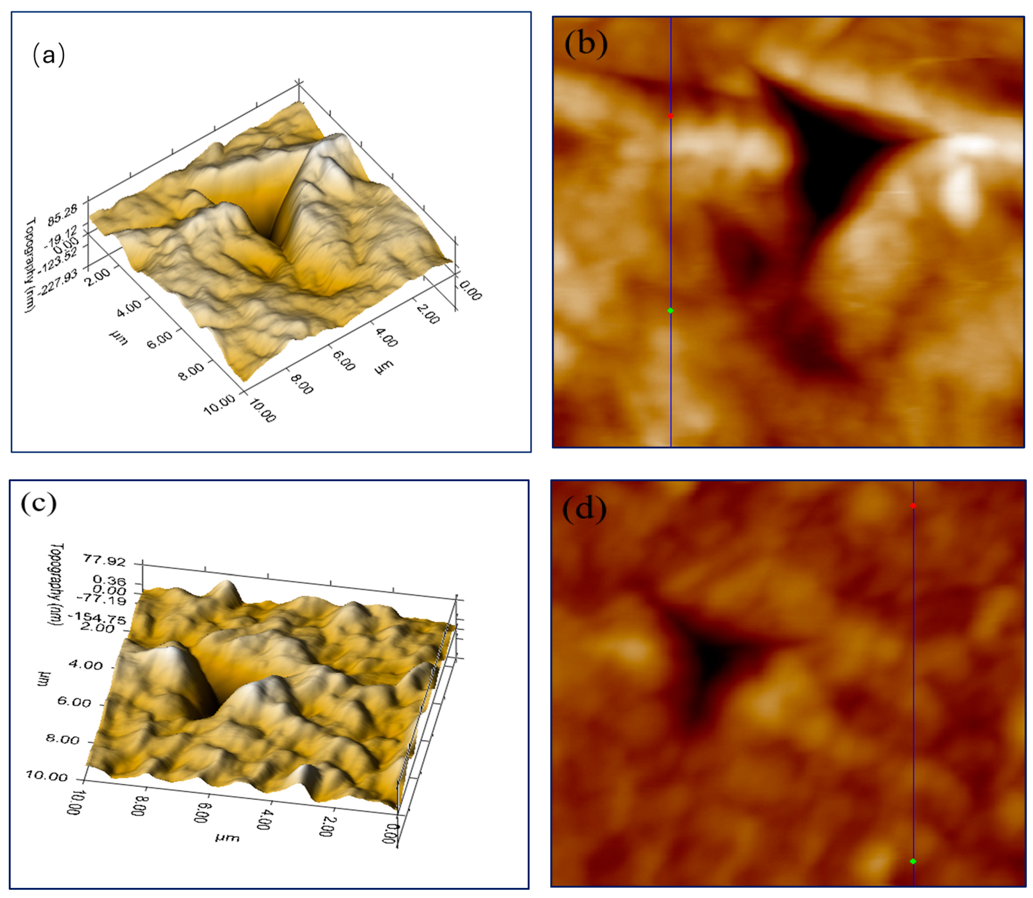
Regardless the contrasting contact depths at 10,000 μN the calculated mechanical parameters are in relatively tight range meaning that there is a presence of more combined elastic-plastic deformation influencing the measurement of hardness and reduced modulus of elasticity. 3D plots of nanoindentation imprints of the composite specimen modified with 4wt% carbon nanotubes and the neat polymer sample were made by in-situ SPM imaging over a surface area of 10 μm × 10 μm. The scans have been done forthwith after the performance of the relevant indentation test and are indicative of mended surface morphology of the monofiller nanocomposite concerning the in–plane recovery at the modified HDPE-based material (see Figure 3). The measured residual penetration depth in the HDPE is 228 nm against 155 nm for the nanocomposite sample. Bearing in mind the experimental values of the contact depths (see Table 2), it can be inferred that the composite structure containing MWCNTs exhibits more expressed elastic behavior. There has to be noted the identical degree of average surface roughness of both samples–14.2 nm for the pure HDPE and 11.3 nm for the nanocomposite 4wt%MWCNT/HDPE, defined by the plotted blue lines in the topography forward SPM images (see Figure 3b,d). Therefore, any negative impact of potential rough surface engendering doubt over the impeccability of the nanoindentation data can be excluded. The nanoindentation pile–up which is formed above the bulk surface of both samples and is more distinct over the pure polymer could be due to the elastic-plastic nature of the region around the tip under load [26]. That difference in the pile–up characteristics between the nanocomposite material and the polymer means that the tailored with carbon nanoparticles HDPE matrix may act on the mechanism of plastic deformation. Wear behavior, as a key property of each one nanocomposite, could be investigated by means of the plasticity index [16], which is an important parameter in the descrying of material lifetime. Extraction of plasticity index from the relevant load-displacement data imposes a subtraction of the creep segment when using the compliance method referring to viscoelastic–plastic material [27]. Calculation of the plasticity index (ψ) of a solid body according the equation, proposed in the paper in question, showed an enhancement in wear resistance of the nanocomposite samples. The values were obtained by taking the ratio between the mathematical area below the indentation loading–unloading curve (corresponding to the plastic work done during the test) and the sum of that area added to the mathematical area situated under the unloading curve referring to the viscoelastic recovery of the material. As expected, the highest reduction in the plasticity index compared to the neat polymer was found for the composition 4wt%MWCNT/HDPE—0.63 against 0.68. The other two polymer-based compositions—4wt%GNP/HDPE and 2wt%GNP2wt%MWCNT/HDPE—were determined to have plasticity indexes of 0.66 and 0.65, respectively.
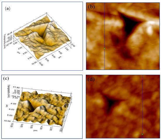
Figure 3.
3D plots of indentation imprints on the surface of neat HDPE (a) and 4wt%MWCNT/HDPE nanocomposite sample (c) as well as topography forward images of the same indentation surface areas (b) and (d) made by in-situ SPM imaging, including estimation of average surface roughness.
Figure 3.
3D plots of indentation imprints on the surface of neat HDPE (a) and 4wt%MWCNT/HDPE nanocomposite sample (c) as well as topography forward images of the same indentation surface areas (b) and (d) made by in-situ SPM imaging, including estimation of average surface roughness.
The relative vicinity of the ψ values could be explained by the high loading rate of 10,000 μN leading to higher penetration depth and therefore to more expressed elastic–plastic response of the composite material that is partially depending on the interaction polymer chains − nanofiller in the nanocomposite structure [28]. On the other hand, the H/E ratio of hardness to elastic modulus is a manner to comprehend the wear rate of a composite sample, as it has to be greater when compared for instance to neat polymer in order to indicate an increased stress required to bring surface deformation [29]. Indentation contact with harder materials possessing enhanced creep resistance should lead to higher H/E values [30], as established for the sample 4wt%MWCNT/HDPE (see Table 3).

Table 3.
Hardness-vs.-elasticity ratio of the polymer compositions as a function of nanoindentation peak load.
Beholding the estimated H/E ratios, it becomes evident that the nanocomposite specimen exhibiting the highest rate of wear at every set indentation peak force is the HDPE material incorporating with 4 wt% MWCNTs. It means not only good plastic behavior coming from the top layer of the sample but also better elastic properties as the probe is going deeper in the composite material when 10,000 μN indentation peak load is applied.
3.2. Nanoscratch Testing
The accent in the implementation of the nanoscratch surface testing of the nanocomposite specimens fell on an accurate calculation of the coefficient of friction taken by the linear part of the curve depicting the friction as correlation between the enclosed by the indenter lateral and normal forces in function of experimental time. Another main objective was the consideration of the amount of pile-up along the scratch groove that can be dependent on the type or combination of carbon nanofillers used as reinforcing material in the composite structure [31]. In general, the formation of side and rear pile-up of material is predetermined by extrinsic parameters as the radius and shape of a Berkovich indenter [32] without ignoring the impact of the interface features in the nanocomposite structure. The amount of surface deformation during nanoscratching depends on the intrinsic mechanical and physical parameters of the material and, as in our case, on the thermoplastic nature of the polymer die [33]. The essential mechanical data obtained from nanoscratch testing, encompassing COF values, magnitude of lateral pile-up, and average surface roughness, can be seen in Table 4.

Table 4.
Coefficient of friction (COF), height of lateral pile-up, and average surface roughness of the composite specimens estimated from nanoscratch mechanical data.
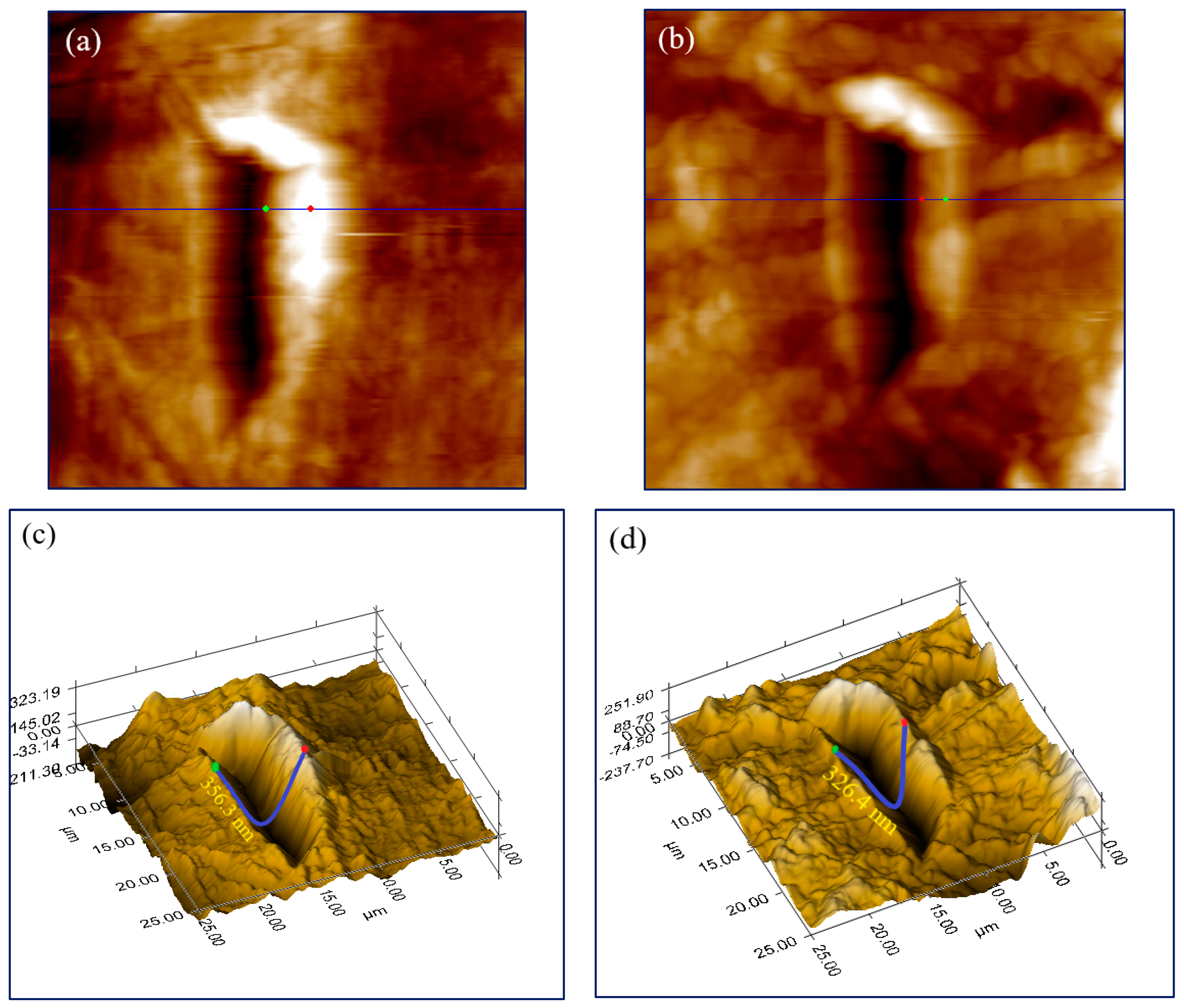
In-situ SPM imaging was used to illustrate the effect of GNPs and MWCNTs in the nanocomposite architecture on the height of material pile-up as a nanomechanical surface peculiarity affecting the study of the samples’ friction behavior (Figure 4a,b). Apparently, the presence of carbon nanotubes in the HDPE matrices of the nanocomposites leads to a lower height of pile-up that can be due to the better elastic and wear resistance properties of these two compositions, as already demonstrated by the nanoindentation analysis. Most significant scratch resilience at a 1000 μN constant load function was ascertained as regards the bifiller composite sample, whose lowest degree of side pile-up means shallowest residual penetration depth (see the 3D plots of scratch grooves in Figure 4c,d). The blue lines denote the loop of the indenter notch measuring the vertical distance of percolation, which was found to be 30 nm shorter with respect to the bifiller hybrid sample in contrast to the neat HDPE. For, the distinguishable elastic behavior of that material could be assigned to the hybrid nanocomposite structure of well-dispersed and interacting carbon nanofillers. On the other hand, the highest coefficient of friction has been calculated with respect to the monofiller nanocomposite containing 4 wt% graphene nanoplatelets—0.401.
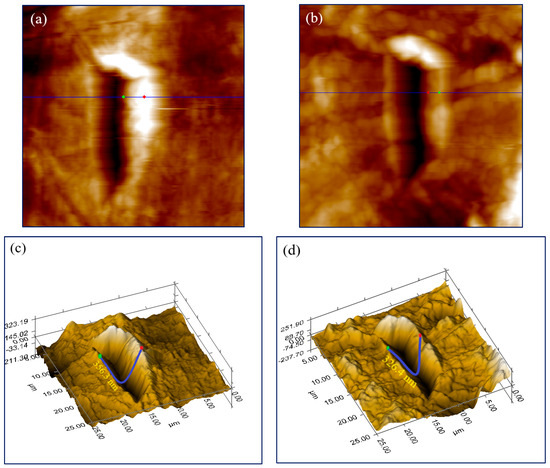
Figure 4.
In-situ SPM topography forward and 3D plot imaging of nanoscratch grooves over the surface of pure HDPE (pictures (a,c)) and over a hybrid composition of 2wt%GNP2wt%MWCNT/HDPE (pictures (b,d)).
This value could signify good scratch resistance as it means a significant stress rendered against the motion of the indenter on the sample surface [29], whereas the mean COFs of the other two nanocomposite materials are due to the registering of lower lateral force. However, it has to be mentioned that along with the high lateral force, there was detected a larger height of side pile-up of 221.1 nm. Therefore, the deeper displacement of the probe pushing away higher quantity of material could be as well a token of lesser scratch hardness of that composition which, bearing in mind the high density of the polymer matrix, will hamper the indenter to move forward when got into the nanocomposite. Another factor influencing the smooth conducting of a successful nanoscratch test is undoubtedly the average surface roughness of the composite samples [34]. It should be pointed out that the monofiller specimen incorporated with 4 wt% MWCNTs has a slightly higher surface roughness of 29.6 nm against 18.4 nm of the hybrid compound 2wt%GNP2wt%MWCNT/HDPE. This finding can partially explain the shift in the height of the measured pile-up on the scratched surface areas of these two nanocomposite samples showing similar friction properties anyway. The distance between the red and the green dots in Figure 4a,b is indicative of the precise measurement of the composite pile-up.
3.3. Thermal Conductivity Measurements
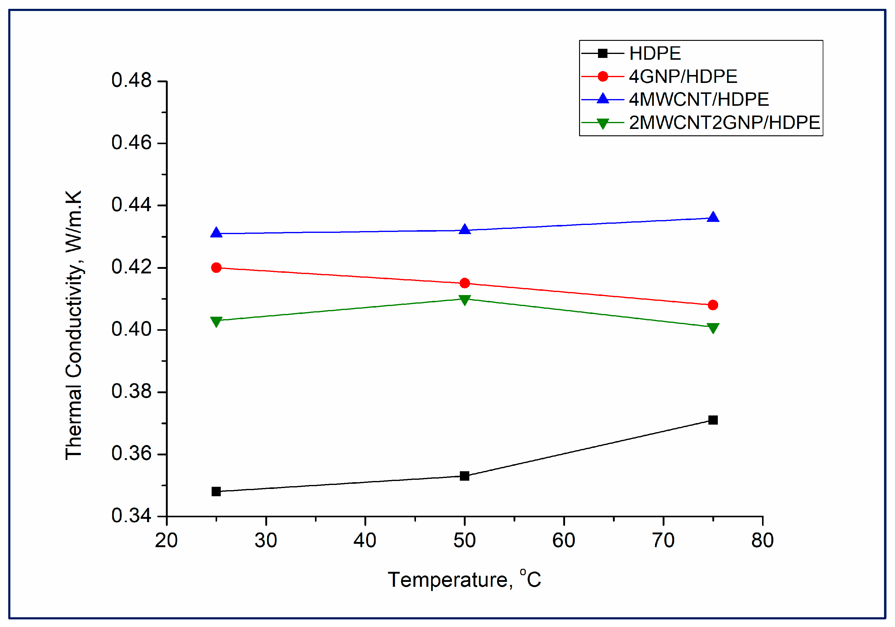
Polymers are usually characterized by very low thermal conductivity (0.1–0.5 W/m.K), which is strongly affected by the complex polymer morphology, crystallinity, molecular orientation, etc. [35]. Enhancing the thermal conductivity of polymers is important for many applications, and it has recently become a strategic research topic. The graphene-based polymer composites are expected to provide superior thermal conductivity due to the exceptional thermal properties of graphene, which are among the highest of any known material [36]. As anticipated, the addition of GNPs and MWCNTs significantly increased the polymer matrix’s thermal conductivity at all set temperatures. It can be seen that the highest thermal conductivity in the nanocomposite range was shown by the compound 4wt%MWCNT/HDPE, and the lowest was exhibited by the hybrid-polymer-based sample 2wt%GNP2wt%MWCNT/HDPE (see Figure 5).
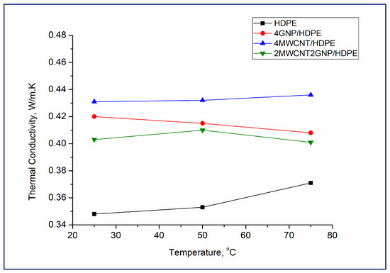
Figure 5.
Thermal conductivity of the composite materials as a function of the testing temperatures.
Generally, the thermal conductivity of a composite material is influenced by several factors, including the intrinsic thermal conductivity of the components, their volume fraction, and the dispersion and alignment of the fillers within the polymer die. These studies state that carbon fillers with a platelet shape are superior to those with other morphologies because of their huge contact area, which allows for considerably tighter contact between neighboring platelets and hence less phonon dispersion [37], but as mentioned above, in this case, the MWCNTs-containing composite has better thermal conductivity than the one reinforced with GNPs. A possible explanation for this phenomenon could be the more uniform dispersion of MWCNTs in the HDPE matrix compared to that of the GNPs, which own the tendency to stack in aggregates. This alleged better dispersion not only enhances the thermal conduction path in the composite, leading to higher thermal conductivity, but also supports the already-discussed superior nanomechanical properties of the sample 4wt%MWCNT/HDPE. Along with the dispersion, the alignment of GNPs and MWCNTs within the polymer matrix, the physical interactions at the interface polymer chain–carbon nanoparticles, and the presence of defects or functional groups in the carbon nanofillers’ structure would altogether affect the thermal conductivity. Furthermore, Kotsilkova et al. [38] discovered that the electrical conductivity of PLA-based composites reinforced with MWCNTs is greater than these ones loaded with GNPs, which under definite conditions, may increase the thermal conductivity of polymer composites via electron transfer, notwithstanding its minor contribution compared to the phonon scattering.
It was also found that over the investigated temperature range, the thermal conductivity of the composites did not undergo any significant change, except for 4wt%GNP/HDPE that displayed a slight lowering trend in thermal conductivity upon increasing temperature. This distinct behavior is probably related to the thermal expansion of the composites leading to variations in the capacity for thermal conductivity. When the temperature goes up, materials typically expand, which can disrupt the conductive pathways and reduce the thermal conductivity. However, the thermal expansion of the samples is small within the temperature range of 25–75 degrees Celsius, so the effect on thermal conductivity is negligible. Moreover, the thermal vibrations of atoms and molecules in these materials are not strong enough to modify their structures keeping a stable phonon scattering mechanisms in the nanocomposite architecture.
3.4. Nanocomposite Electrical Properties
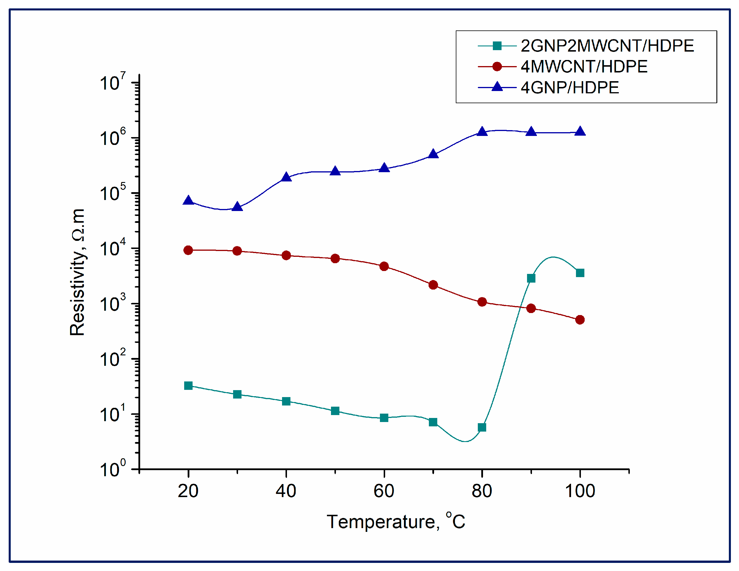
It has been observed that the composite sample with a 4 wt% GNP content as well as the hybrid nanocomposite 2wt%GNP2wt%MWCNT/HDPE exhibit a positive temperature coefficient (see Figure 6). It should be noted that the bifiller composite shows a percolation above 80 degrees, whereafter the resistance rises sharply. The reason of this leap in resistivity can be the joint work of the GNPs and MWCNTs in the hybrid material, establishing a more effective conductive network in the polymer matrix. The graphene particles, with their flat, plate-like structures, provide a large surface area for the conductive network, while the carbon nanotubes, with their tubular structures, provide the necessary interconnections between the graphene nanoplatelets. This combination results in an interconnected conductive network that is more sensitive to the thermal expansion of the HDPE matrix. Compared to the bifiller composite, the composition 4wt%GNP/HDPE demonstrated a smooth increase in resistance as well as higher electrical resistivity due to the not-well-established conductive network. In contrast, at the nanocomposite 4wt%MWCNT/HDPE, MWCNTs are the primary conductive particles, and their structures allow them to form a more interconnected conductive network in the polymer die, which is more stable and was not affected by thermal expansion; therefore, its resistivity hardly changes in the studied temperature range.
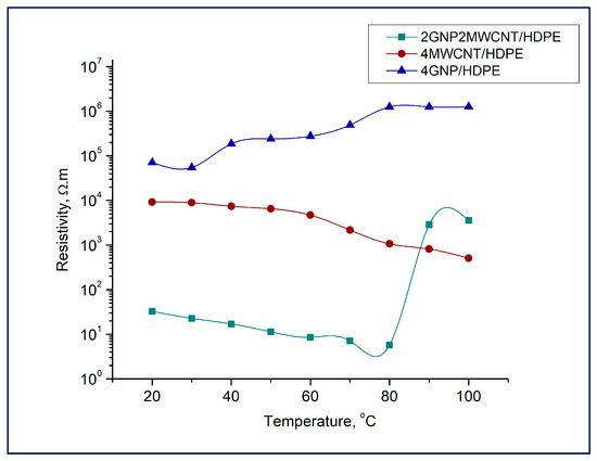
Figure 6.
Resistivity measurements of the nanocomposite structures in the temperature range of 20–100 °C.
3.5. Scanning Electron Microscopy Analysis
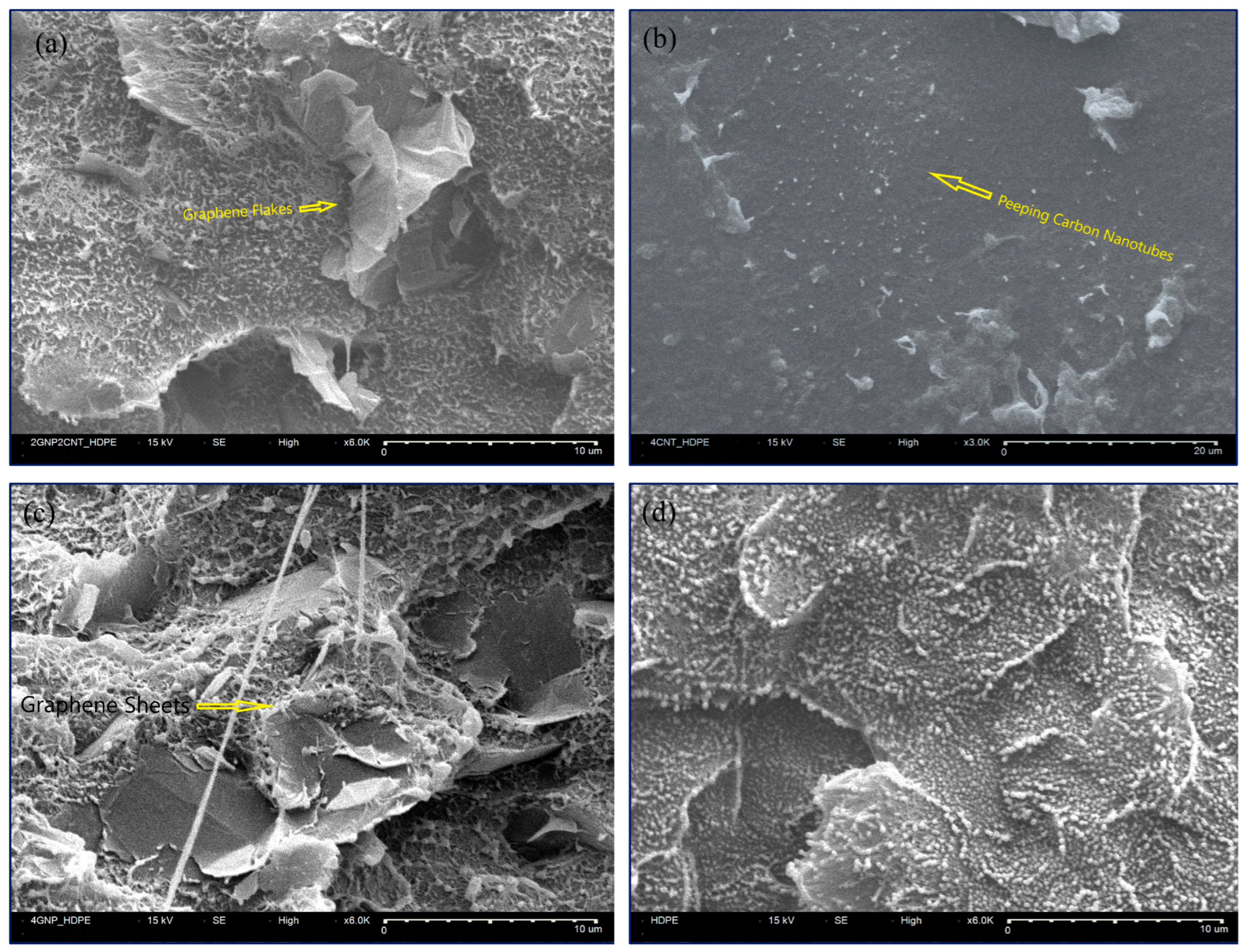
The presence and uniform distribution of the carbon nanofillers disposed in the HDPE matrix have been disclosed by applying the scanning electron microscopy instrumental technique. SEM images of the pristine GNPs and MWCNTs verified their high-quality morphological parameters (see Figures S1 and S2). Two types of nanocomposite sample pretreatment, including cross-sectional breaking under liquid nitrogen or acid-etching procedure [20], were tested because of the specifics of the crystalline spherulite morphology of HDPE hindering the readily disclosure of the carbon nanoparticles. Distinguishable graphene flakes popping out from the composite matrix (Figure 7a) or laying down over its cross-sectional surface (Figure 7c) were observed by SEM imaging using a secondary electron detector. The scans have been performed right after the cutting of the samples made in liquid nitrogen in order to avoid the impending polymer relaxation that would not allow the visualization of the carbon nanofillers. A heap of well-dispersed carbon nanotubes can be seen on the surface of the etched monofiller nanocomposite sample 4wt%MWCNT/HDPE (Figure 7b), explaining its already-established excellent nanomechanical and thermal properties. A comparison between that SEM micrograph and the SEM image of the neat polymer, which has not experienced acid etching (Figure 7d), discloses the adequacy of this type of sample pretreatment, leading to the removal of the upper spherulite layer and uncovering of the carbon nanotubes in the composite structure (see Figure 7b).
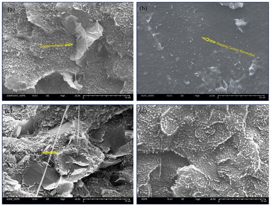
Figure 7.
SEM micrographs of the following specimens: 2wt%GNP2wt%MWCNT/HDPE (a), 4wt%MWCNT/HDPE (b), 4wt%GNP/HDPE (c), and the pure HDPE as a reference (d).
4. Conclusions
Looking up the input of graphene nanoplatelets and carbon nanotubes in the nanomechanical behavior of HDPE-based composite materials led to an inference that the reinforcing effect of MWCNTs is superior compared to the GNPs, surpassing even the hybrid combination of both carbon nanofillers. However, the scratch resistance of the bifiller composition being defined by the quantity of lateral pile-up and the relatively low break-in of the indenter on the material surface is indicative for best friction behavior. As approved by the SEM analysis, the fine carbon nanotube distribution in the polymer matrix could be the factor that braces the high mechanical performance of the specimen possessing 4 wt% MWCNTs with its excellent thermal conductivity at all testing temperatures. The investigation of the indentation size effect on the nanomechanical parameters of the composite samples unveiled that at shallower penetration there is a more noticeable plastic response of the materials. When going deeper into the nanocomposite sample surface, the combined elastic–plastic zone is being reached, which can be the reason of receiving closer mechanical data for nanohardness and reduced modulus of elasticity. There has been also ascertained that both carbon nanofillers have a positive impact on the wear resistance of the new composite materials. Overall, it has to be noted that the implementation of novel two steps in the nanocomposite preparation strategy was a good approach, resulting in the elaboration of new materials having nanomechanical, thermal, and electric properties exceeding the output HDPE matrix.
Supplementary Materials
The following supporting information can be downloaded at https://www.mdpi.com/article/10.3390/app14219961/s1. Figure S1: SEM image of pristine GNPs; Figure S2: SEM image of pristine MWCNTs.
Author Contributions
Conceptualization, T.B.; methodology, V.A.; validation, T.B., V.G. and J.I.A.-T.; investigation, T.B., V.G. and J.I.A.-T.; resources, E.I. and R.K.; data curation, T.B. and V.G.; writing—original draft preparation, T.B. and V.G.; writing—review and editing, E.I. and D.M.H.; visualization, T.B.; supervision, R.K.; project administration, E.I. and D.M.H.; funding acquisition, E.I. All authors have read and agreed to the published version of the manuscript.
Funding
This research was funded by the European Union’s Horizon 2020–MSCA–RISE–871163–ReACTIVE Too Project. The current study has also received funding by the Bulgarian National Science Fund under the project KP-06-H77/4-2023.
Data Availability Statement
All raw data that are in the fundamental of the results presented in this study can be provided by the corresponding author on request.
Conflicts of Interest
Authors Todor Batakliev, Evgeni Ivanov and Vladimir Georgiev were employed by the company NanoTech Lab Ltd. The remaining authors declare that the research was conducted in the absence of any commercial or financial relationships that could be construed as a potential conflict of interest.
References
- Kumar, A.; Sharma, K.; Dixit, A.R. Carbon nanotube- and graphene-reinforced multiphase polymeric composites: Review on their properties and applications. J. Mater. Sci. 2020, 55, 2682–2724. [Google Scholar] [CrossRef]
- Mohan, S.; Olley, R.H.; Vaughan, A.S.; Mitchell, G.R. Evaluating Scales of Structures. In Controlling the Morphology of Polymers; Mitchell, G., Tojeira, A., Eds.; Springer: Cham, Switzerland, 2016; pp. 29–67. [Google Scholar]
- Hossain, M.I.; Chowdhury, M.A.; Mahamud, S.; Saha, R.K.; Zahid, M.S.; Ferdous, J.; Hossain, N.; Mobarak, M.H. Electro-mechanical analysis of nanostructured polymer matrix composite materials for 3D printing using machine learning. Chem. Eng. J. Adv. 2024, 19, 100626. [Google Scholar] [CrossRef]
- Desnoes, E.; Deshaies, P.; Bideau, B.; Rubiano, J. Thermoformed products from high-density polyethylene and Softwood kraft pulp. Nord. Pulp. Pap. Res. J. 2024, 39, 339–348. [Google Scholar] [CrossRef]
- Kadhim, B.J.; Mahdi, A.H.; Al-Mutairi, N.H. Mechanical and Thermal Properties of PP/HDPE Blends Reinforced with ZnO Nanoparticles for Industrial Applications. Int. J. Nanoelectron. Mater. 2024, 17, 479–486. [Google Scholar] [CrossRef]
- Sahu, S.K.; Badgayan, N.D.; Samanta, S.; Rama Sreekanth, P.S. Quasistatic and dynamic nanomechanical properties of HDPE reinforced with 0/1/2 dimensional carbon nanofillers based hybrid nanocomposite using nanoindentation. Mat. Chem. Phys. 2018, 203, 173–184. [Google Scholar] [CrossRef]
- Rajeshwari, P.; Rao, V.V.; Dey, T.K. Depth-Sensing Indentation and Nano-Dynamic Mechanical Properties of Aluminum Nitride Nanoparticles Reinforced High Density Poly-Ethylene Nanocomposites. Polym. Compos. 2017, 40, 240–254. [Google Scholar] [CrossRef]
- Rajeshwari, P.; Dey, T.K. Novel HDPE nanocomposites containing aluminum nitride (nano) particles: Micro-structural and nano-mechanical properties correlation. Mat. Chem. Phys. 2017, 190, 175–186. [Google Scholar] [CrossRef]
- Rajeshwari, P. Kinetic analysis of the non-isothermal degradation of high density polyethylene filled with multi-wall carbon nanotubes. J. Therm. Anal. Calorim. 2016, 123, 1523–1544. [Google Scholar] [CrossRef]
- Mohammadi, M.; Ziaie, F.; Majdabadi, A.; Akhavan, A.; Shafaei, M. Improvement of mechanical and thermal properties of high energy electron beam irradiated HDPE/hydroxyapatite nano-composite. Radiat. Phys. Chem. 2017, 130, 229–235. [Google Scholar] [CrossRef]
- Bajwa, D.S.; Chanda, S.; Ryan, C.; Bajwa, S.G.; Stark, N.; Matteson, K. Graphene quantum dots/cellulose nanocrystal inclusion complex for enhancing the physical and thermal properties of HDPE polymer matrix. Carbohydr. Polym. Technol. Appl. 2024, 7, 100450. [Google Scholar] [CrossRef]
- Li, H.-X.; Russell, T.P.; Wang, D. Nanomechanical and Chemical Mapping of the Structure and Interfacial Properties in Immiscible Ternary Polymer Systems. Chin. J. Polym. Sci. 2021, 39, 651–658. [Google Scholar] [CrossRef]
- Hosoya, R.; Morita, H.; Nakajima, K. Analysis of Nanomechanical Properties of Polyethylene Using Molecular Dynamics Simulation. Macromolecules 2020, 53, 6163–6172. [Google Scholar] [CrossRef]
- Al Rez, M.F.; Alothman, O.Y.; Fouad, H.; Mahmood, A.; Alfotawi, R.; Ansari, S.G.; Fouad, M.; Hashem, M.; Al-Jassir, F.F. Stromal Cells Attachment, Proliferation and Nano-Mechanical Behavior of High Density Polyethylene/Carbon Nanotubes/Nanoclay as Artificial Hip and Knee Joint Bearing Material. Nanosci. Nanotechnol. Lett. 2016, 8, 846–852. [Google Scholar] [CrossRef]
- Sreekanth, P.S.R.; Kanagaraj, S. Assessment of bulk and surface properties of medical grade UHMWPE based nanocomposites using Nanoindentation and microtensile testing. J. Mech. Behav. Biomed. 2013, 18, 140–151. [Google Scholar] [CrossRef] [PubMed]
- Badgayan, N.D.; Samanta, S.; Sahu, S.K.; Siva, S.B.V.; Sadasivuni, K.K.; Sahu, D.; Sreekanth, P.S.R. Tribological behaviour of 1D and 2D nanofiller based high density polyethylene hybrid nanocomposites: A run-in and steady state phase analysis. Wear 2017, 376–377, 1379–1390. [Google Scholar] [CrossRef]
- Han, C.-S. Influence of the molecular structure on indentation size effect in polymers. Mater. Sci. Eng. A 2010, 527, 619–624. [Google Scholar] [CrossRef]
- Han, C.S.; Sanei, S.H.R.; Alisafaei, F. On the origin of indentation size effects and depth dependent mechanical properties of elastic polymers. J. Polym. Eng. 2016, 36, 103–111. [Google Scholar] [CrossRef]
- Batakliev, T.; Ivanov, E.; Angelov, V.; Spinelli, G.; Kotsilkova, R. Advanced Nanomechanical Characterization of Biopolymer Films Containing GNPs and MWCNTs in Hybrid Composite Structure. Nanomaterials 2022, 12, 709. [Google Scholar] [CrossRef]
- Tantry, S.; Anantharaman, D.; Thimmappa, B.H.S.; Kamalakaran, R. Studying banded spherulites in HDPE by electron microscopy. Polym. Test. 2020, 89, 106631. [Google Scholar] [CrossRef]
- Oliver, W.C.; Pharr, G.M. An Improved Technique for Determining Hardness and Elastic Modulus Using Load and Displacement Sensing Indentation Experiments. J. Mater. Res. 1992, 7, 1564–1583. [Google Scholar] [CrossRef]
- Batakliev, T.; Georgiev, V.; Angelov, V.; Ivanov, E.; Kalupgian, C.; Muñoz, P.A.R.; Fechine, G.J.M.; Andrade, R.J.E.; Kotsilkova, R. Synergistic Effect of Graphene Nanoplatelets and Multiwall Carbon Nanotubes Incorporated in PLA Matrix: Nanoindentation of Composites with Improved Mechanical Properties. J. Mater. Eng. Perform. 2021, 30, 3822–3830. [Google Scholar] [CrossRef]
- Alisafaei, F.; Han, C.-S.; Lakhera, N. Characterization of indentation size effects in epoxy. Polym. Test. 2014, 40, 70–78. [Google Scholar] [CrossRef]
- Peng, C.; Zeng, F. Modeling the indentation size effects of polymers, based on couple stress elasticity and shear transformation plasticity. Arch. Appl. Mech. 2022, 92, 3661–3681. [Google Scholar] [CrossRef]
- Badgayan, N.D.; Sahu, S.K.; Samanta, S.; Sreekanth, P.S.R. An insight into mechanical properties of polymer nanocomposites reinforced with multidimensional filler system: A state of art review. Mater. Today Proc. 2020, 24, 422–431. [Google Scholar] [CrossRef]
- Mallikarjunachari, G.; Ghosh, P. Analysis of strength and response of polymer nano thin film interfaces applying nanoindentation and nanoscratch techniques. Polymer 2016, 90, 53–66. [Google Scholar] [CrossRef]
- Briscoe, B.J.; Fiori, L.; Pelillo, E. Nano-indentation of polymeric surfaces. J. Phys. D Appl. Phys. 1998, 31, 2395–2405. [Google Scholar] [CrossRef]
- Shen, L.; Phang, I.Y.; Liu, T.; Zeng, K. Nanoindentation and morphological studies on nylon 66/organoclay nanocomposites. II. Effect of strain rate. Polymer 2004, 45, 8221–8229. [Google Scholar] [CrossRef]
- Tserpes, K.I.; Chanteli, A.; Pantelakis, S.; Koumoulos, E.P.; Charitidis, C.A. Mechanical and nanomechanical properties of MWCNT/PP nanocomposite. Frat. Ed Integrità Strutt. 2018, 12, 73–83. [Google Scholar] [CrossRef]
- Koumoulos, E.P.; Jagadale, P.; Lorenzi, A.; Tagliaferro, A.; Charitidis, C.A. Evaluation of surface properties of epoxy-nanodiamonds composites. Compos. B Eng. 2015, 80, 27–36. [Google Scholar] [CrossRef]
- Shokrieh, M.M.; Hosseinkhani, M.R.; Naimi-Jamal, M.R.; Tourani, H. Nanoindentation and Nanoscratch Investigations on Graphene—Based Nanocomposites. Polym. Test. 2013, 32, 45–51. [Google Scholar] [CrossRef]
- Gibson, R.F. A review of recent research on nanoindentation of polymer composites and their constituents. Compos. Sci. Technol. 2014, 105, 51–65. [Google Scholar] [CrossRef]
- Mallikarjunachari, G.; Ghosh, P. Pile-up response of polymer thin films to static and dynamic loading. Thin Solid Films 2019, 677, 1–12. [Google Scholar] [CrossRef]
- Wang, Z.; Gu, P.; Zhang, H.; Zhang, Z.; Wu, X. Indenter geometrical effects on sub-micro/nano indentation and scratch behaviors of polymeric surfaces. Mech. Adv. Mater. Struct. 2016, 23, 291–300. [Google Scholar] [CrossRef]
- Li, A.; Zhang, C.; Zhang, Y.F. Thermal conductivity of graphene-polymer composites: Mechanisms, properties, and applications. Polymers 2017, 9, 437. [Google Scholar] [CrossRef]
- Balandin, A. Thermal properties of graphene and nanostructured carbon materials. Nature Mater. 2011, 10, 569–581. [Google Scholar] [CrossRef]
- Tarani, E.; Terzopoulou, Z.; Bikiaris, D.N.; Kyratsi, T.; Chrissafis, K.; Vourlias, G. Thermal conductivity and degradation behavior of HDPE/graphene nanocomposites. J. Therm. Anal. Calorim. 2017, 129, 1715–1726. [Google Scholar] [CrossRef]
- Kotsilkova, R.; Ivanov, E.; Georgiev, V.; Ivanova, R.; Menseidov, D.; Batakliev, T.; Angelov, V.; Xia, H.; Chen, Y.; Bychanok, D.; et al. Essential Nanostructure Parameters to Govern Reinforcement and Functionality of Poly(lactic) Acid Nanocomposites with Graphene and Carbon Nanotubes for 3D Printing Application. Polymers 2020, 12, 1208. [Google Scholar] [CrossRef]
Disclaimer/Publisher’s Note: The statements, opinions and data contained in all publications are solely those of the individual author(s) and contributor(s) and not of MDPI and/or the editor(s). MDPI and/or the editor(s) disclaim responsibility for any injury to people or property resulting from any ideas, methods, instructions or products referred to in the content. |
© 2024 by the authors. Licensee MDPI, Basel, Switzerland. This article is an open access article distributed under the terms and conditions of the Creative Commons Attribution (CC BY) license (https://creativecommons.org/licenses/by/4.0/).

