Abstract
In electromechanical systems, backlash in gear trains can lead to a degradation in control performance. We propose a drive–anti-drive mechanism to address this issue. It consists of two DC motors that operate in opposite directions. One motor acts as the drive, while the other serves as the anti-drive to compensate for the backlash. This work focuses on switching between the drive and anti-drive motors, controlled by a switched-mode PID controller. Simulation results on an inverted pendulum demonstrate that the proposed scheme effectively compensates for backlash, improving position accuracy and control. This switched controller approach enhances the performance of electromechanical systems, particularly where gear backlash poses challenges to closed-loop performance.
1. Introduction
In electromechanical system positional analysis, backlash is an undesired problem. Understanding the root causes and implementing effective mitigation techniques significantly reduce the negative impacts of backlash on positional stability, resulting in more accurate and reliable positional control systems. This problem can arise in any mechanical system that incorrectly couples the driving gear and the driven gear. This issue eventually results in positional errors, as noted by [1,2,3]. Therefore, it is essential to reduce the impact of backlash in these systems.
It is critical to identify its parameters in order to avoid backlash. This common problem is a popular area of research. In recent years, researchers have developed a multitude of approaches and models to identify backlash parameters and have implemented numerous compensatory techniques to overcome this nonlinearity. Using the proper switching function and its complements, the first analytical description of backlash was presented in [4]. The asymmetric backlash system’s equation partitions the backlash parameters, allowing it to approach their estimate as a quasi-linear issue. However, it can be approached incrementally by estimating internal variables. Karim et al. [5] presented a simplified rack and pinion model, which was used to avoid a convoluted approach for parameter estimation.
A control-based method successfully mitigated the detrimental effects of friction and backlash by using a reduced rack and pinion arrangement and measuring the current acceleration of the drive. But gears are prone to deterioration. As a result of gear wear, backlash qualities frequently change. In order to successfully adjust for backlash, it is crucial to keep track of how the backlash parameters change over time. Based on this discovery, dynamic models for backlash in gears with time-varying behavior were introduced in past works [6,7].
In 2019, Yi et al. [6] introduced a novel nonlinear dynamic model for spur gears. This model considers several factors such as pressure angle variation with time, gear backlash behaviors, gear gravitational effects, geometrical imbalance in mass, and excitations. A study by Park (2020) [7] looked at how spur gears move and react by starting with the gears in the backlash and using meshes that change over time and with bearing stiffness.
Hysteresis nonlinearities were described by a set of differential equations by Huo 2019 [8]. Yamada [9] used the load-side encoder’s information to achieve high precision; the method accounted for backlash by using a precise joint-control method. The load-side encoder information effectively compensated for the backlash effect in a feed-forward manner.
Dead zone linearity has been extensively used by the researchers for defining the backlash [10,11,12]. The accuracy and performance of servo tracking are improved if the estimation of dead zones is done correctly, as done in [11,12]. To deal with backlash, a predictive control strategy was applied in [13] for an electric power train system with backlash. To overcome the immeasurable system states, the researchers used a switched Kalman filter. Rostiti [14] presented a novel backlash compensator for automotive drivetrains, realized via real-time model predictive control. Since predictive control strategies need to perform calculations over and over, different adaptive control methods for backlash compensation were also created by [15,16,17,18,19,20,21].
An adaptive robust controller was designed without using the inverse backlash model developed by Abher et al. [20] for robot manipulators with unknown backlash in robot joint gears. The fact that the controller did not use the inverse backlash method made it less complex. Wei et al. (2018) created a boundary controller for a flexible robotic manipulator to handle the system’s backlash [21]. Wang et al. [22] devised an adaptive technique for compensating for backlash in a solid-ducted rocket, utilizing touch-state observation. The strategy successfully reduced the duration of the transition and minimized the hysteresis effects on the control system.
Guofa et al. [23] devised a method to estimate vibration torque as well as system states. A designed extended-state observer used those estimated parameters to obtain feed-back and feed-forward signals.
Sun et al. [24] also came up with a new way to fix servo systems that have backlash. It is called variable gain-switching accurate differential observer-based compensation control for servo systems with backlash. The variable gain technique was devised to accurately predict the unknown system states and adjust for the influence of backlash based on the mathematical model of switching backlash torque. The estimation was conducted using the Kalman filter, taking into account the backlash as a parameter and incorporating it as a state in the dynamics. The backlash was estimated using local measurements of the DFIG system.
Sven et al. [25] used dual-motor drives to compensate for backlash. One of the drives acted like a rotational spring to close the gap between the gears. Thus, it is responsible for eliminating backlash. Two degrees of freedom backlash-free mechanisms have been established by using the drive–anti-drive mechanism through cooperative control by Haider et al. [26].
Contributions
This study proposes a drive–anti-drive control strategy to compensate for gear backlash using two unidirectional drives. Unlike traditional methods requiring extensive mathematical modeling, our approach uses a hybrid switched PID controller to mitigate backlash effectively. The inverted pendulum, a common benchmark for simulating real-life problems like spacecraft dynamics, as in [27], is used to demonstrate this method.
By employing three PID controllers and a dynamic switching strategy, the system selects the appropriate control input based on the mode, driving both the drive and anti-drive motors. Quantitative evaluations show significant improvements in performance metrics, such as root mean square error (RMSE), rise time, settling time, and overshoot, compared to single-drive systems.
The organization of paper is as follows.
Section 2 introduces the drive–anti-drive mechanism, while Section 3 delves into the switched control strategy within this mechanism. Section 4 provides a comparative performance analysis between a single-drive system and the drive–anti-drive mechanism. Additionally, it includes simulation results for an inverted pendulum using a switched PID controller for the drive–anti-drive mechanism and a PID controller without the anti-drive feature. Finally, Section 5 offers discussions and conclusions regarding the switched-mode PID controller used for backlash compensation.
2. Mathematical Model of a Drive–Anti-Drive System
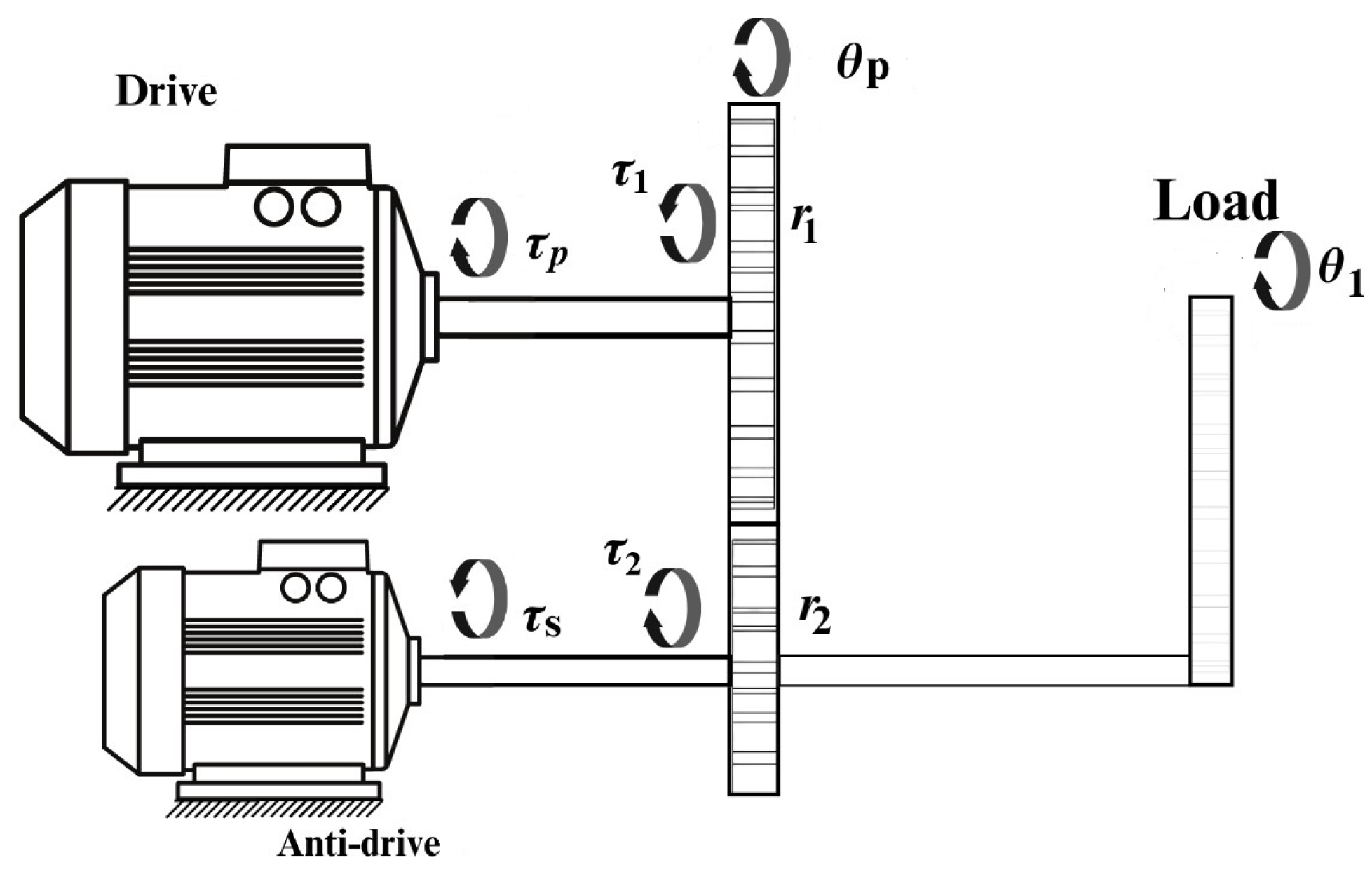
Backlash-free mechanisms ensure smooth running of any manipulator based mechanisms. In this paper, we propose a drive–anti-drive mechanism to compensate for the backlash. The drive–anti-drive mechanism utilizes two drives by applying torques in the opposite directions. Therefore, the controllers are designed to track the reference trajectories for various robotic applications. This mechanism works on the principle of applying torque in the opposite direction to ensure mesh in the gear trains remain intact. Whenever, the drive undergoes change in a direction, anti-drive provides the torque in the opposite direction to compensate for the backlash. The whole assembly is shown in Figure 1.

Figure 1.
Inverted pendulum driven by the drive–anti-drive mechanism.
The inverted pendulum is driven by dual drives; one of the generated torques in an inverted pendulum occurs under the action of gravity, pulling it downwards. The angular position and angular velocity of the pendulum are taken as state variables. The inverted pendulum is driven by two drives that work in switching modes: they will turn on either the drive or anti-drive. The dynamics of the pendulum are given by
The resultant torque on the drive shaft is equal to the difference between the two torques. We can write the dynamics of the drive shaft as follows:
where and are the angular position and angular velocity of the drive motor, respectively.
The driving gear is designated as gear 1, whose angular displacement is given as . The driven gear is designated as gear 2, whose angular position is given as . Their operating pitch radii are given as and , respectively. The gears are operated in three modes. When the driving gear moves with a slight displacement of rotation and two gears lose contact, then the gears are in backlash. When the driving and driven gears maintain perfect contact, the contact is established. In the contact mode, gears are modeled as a spring and damper system. When two gears come into contact, their teeth engage with each other. During this engagement, the impact forces result in relative motion and contact between the teeth. Therefore, it is modeled as a collision. The spring component represents the stiffness of the material of the gear teeth. When the teeth come into contact and experience an impact force, they deform slightly, analogously to compressing a spring. The stiffness coefficient is denoted as . The larger the stiffness, the lesser the deformation of the spring. The damper component represents the damping action that dissipates energy due to the impact, subjecting to how energy is dissipated when compressing a spring with a shock absorber attached. The damping coefficient, denoted as , is proportional to the relative velocity between the gear teeth. This means that, the faster the relative motion between the teeth, the greater the damping force opposing that motion. By modeling the gear teeth interaction during impact as a spring–mass–damper system, designers can better understand and predict the behavior of gear systems in real systems during collisions and improve their designs for efficiency and durability. Impact torques are described for the three modes as positive, negative, and backlash modes, as defined by [28]. Here, refers to the positive contact of gears, refers to backlash mode, and refers to the negative contact of gears.
Here, and .
The gear ratio is given by and B is the backlash in the system.
The electrical network of the drive–anti-drive system is given in Figure 2, where and are the armature resistance, inductance, supply voltage, and current, respectively, through the anti-drive electric circuit. and are the armature resistance, inductance, supply voltage, and current through the drive, respectively. Armature currents of both drives and anti-drives are also taken as state variables in the model. The applied voltages for both drive and anti-drive are taken as the inputs to the system.
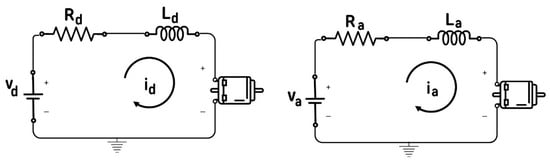
Figure 2.
Electrical network of the drive.
The electrical model of the drive is given by
The torque of the motor is directly proportional to the current; therefore,
The electrical network of the anti-drive is represented below:
The state vector of the entire system is
The output of the system is given below:
The inputs of the system are the voltages of the drive and anti-drive. Therefore, the input vector of the system is given by
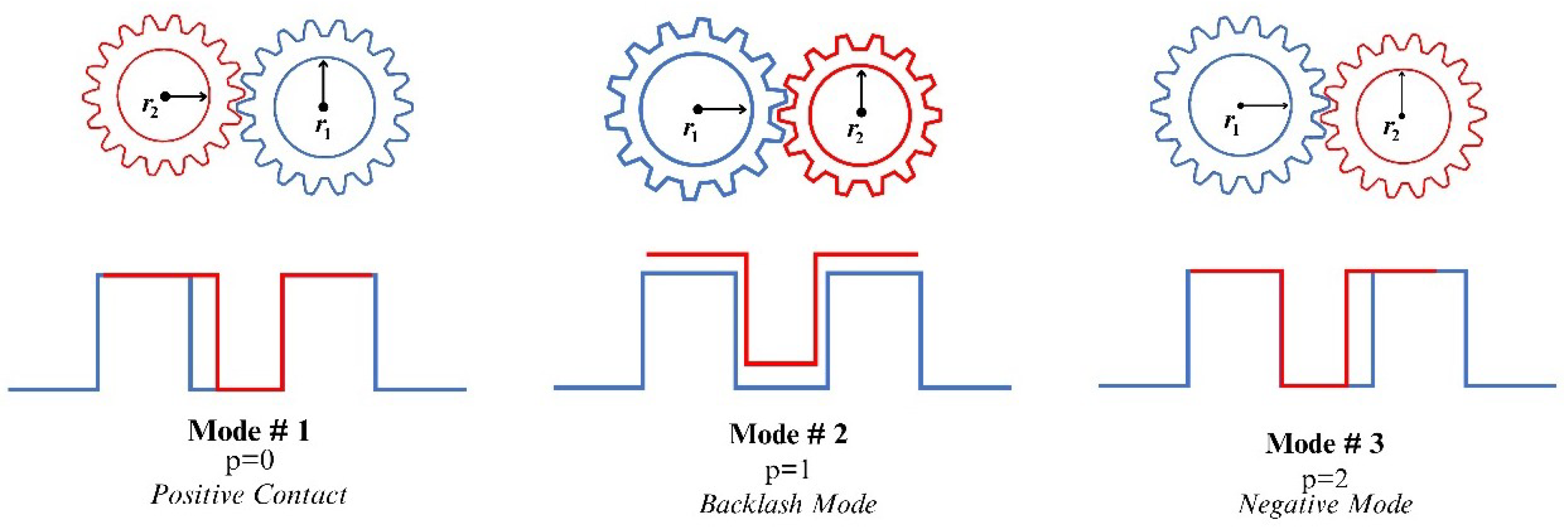
The switching algorithm switches to the appropriate controller, depending upon the current mode of the system. Position of gears for varying p are depicted in the Figure 3.
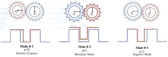
Figure 3.
Three modes of gears.
The dynamics of the system are modeled using the following hybrid model:
For , the system dynamics are given by the following equations:
For , the system dynamics are given by the following equations:
For , the system dynamics are given by the following equations:
The equilibrium points are evaluated for the nonlinear system as a solution to . The equilibrium points of the system are calculated to be , where n is a natural number. For each mode p, the nonlinear dynamics are linearized around the equilibrium point at the origin. It is assumed that the angular displacement of the pendulum is small enough to approximate the angular displacement of the pendulum, such that ; the linearized system dynamics are described below:
where
and
The hybrid controller works in three modes, where represents positive contact, represents the backlash mode, and represents negative contact. These three modes define the dynamics and contact principles of the geared mechanism.
3. Controller Design
Switching between PID controllers has been designed for the hybrid model, where the dynamics of the system change whenever the contact between gears changes. Three separate PID controllers are designed here. Whenever the drive undergoes changes in its direction, the backlash mode is activated. One PID controller is tuned for positive contact and the second is tuned for negative contact. Switching controllers allows the system to become operational under the desired operating conditions.
The method described in this section for the compensation of backlash operates the controller in these modes. However, switching modes are dependent on the monitoring of the angular position of pendulum, as explained in the algorithm defined in Algorithm 1.
Depending on the evaluation of this condition, it assigns a value to the output variable p. The explanation of the logical conditions is given below.
The controller has been assigned a reference trajectory against which it compares the angular position of the inverted pendulum. This comparison generates an error signal. The error signal is then utilized to adjust the parameter values of , , and , . This compensation aims to effectively eliminate backlash within the vibratory system.
Here, y is the output of the controller and is the reference trajectory. The generated error signal is subsequently fed into the controller to prompt the desired response. Three distinct controllers are employed to mitigate the backlash. The selection of the appropriate controller relies on the value of parameter p.
| Algorithm 1 Switched-Mode Controller |
|
A switched-mode PID controller is used to regulate the dynamics of the inverted pendulum. This controller effectively adjusts the voltages for both drive and anti-drive mechanisms, which are subsequently applied to the inverted pendulum system. The activation of the switched-mode PID controller in Algorithm 2, is dependent on the computed value of parameter ‘p’, derived through a dedicated Algorithm 1. In the context of designing control systems, step responses for three separate controllers have been defined and developed. Each controller utilizes a PID (Proportional–Integral–Derivative) control scheme, tailored with a specific design focus. The design focus, in this case, emphasizes the use of reference trajectory tracking as a primary feature. The drive and anti-drive controllers are defined as and . Three separate PID controllers and PID selections are defined as . For , the drive will take the values from controller 0 and the anti-drive will stay off. When the system enters backlash mode, controller 0 will give the input to the drive and controller 1 will give its input to the anti-drive. For p = 2, the drive is driven by controller 2.
To achieve this, the controllers were tuned with a phase margin set to 80 degrees. This choice of phase margin is indicative of a robust control system design, ensuring stability and performance margins within the control loop.
| Algorithm 2 p Mode selection for drive and anti-drive |
|
The PID controllers were developed using MATLAB R2022’s pidtune function, which automates the tuning process based on specified design criteria. In this scenario, the design focus parameter was crucial in guiding the tuning process towards optimizing the controllers for the accurate tracking of reference trajectories. Design Focus parameters were displayed in Table 1.

Table 1.
PID controller parameters.
By setting the phase margin to 80 degrees, the controllers were tailored to exhibit robust stability characteristics while also meeting the requirements for precise reference trajectory tracking. This balance between stability and performance is essential for ensuring effective control system operation in real-world applications.
Furthermore, useful information of cross over frequency and phase margins of each individual controller is depicted in Table 2.
Table 2.
PID controller information parameters.
For validating the results, the proposed mathematical model was implemented on the geared drives. The Parameters of Dual drives (which includes Drive and AntiDrive), primary and secondary gears used for simulation of the case in hand are being mentioned in Table 3 and Table 4 respectively.
Table 3.
DC motor parameters.
Table 4.
Driving and driven gears.
Figure 4 depicts the overall control system of the inverted pendulum. The pendulum is assumed to be rigid and has uniformly distributed mass. External disturbances (e.g., wind, vibrations) are ignored or assumed to be negligible. Each controller calculates the voltages for the drive and anti-drive, which are then used to apply forces to the pendulum in order to counteract any backlash. Each controller is responsible for stabilizing or controlling a specific aspect of the pendulum’s motion in the desired mode. PID controller tuning methods aim to adjust the controller parameters to achieve the desired crossover frequency and phase margin, ensuring the stability and performance of the closed-loop control system.
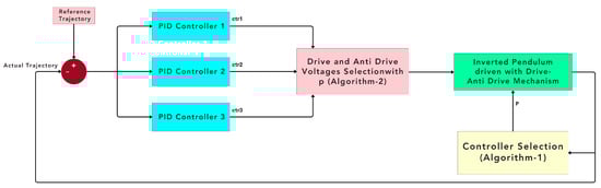
Figure 4.
Schematic diagram of the drive–anti-drive system.
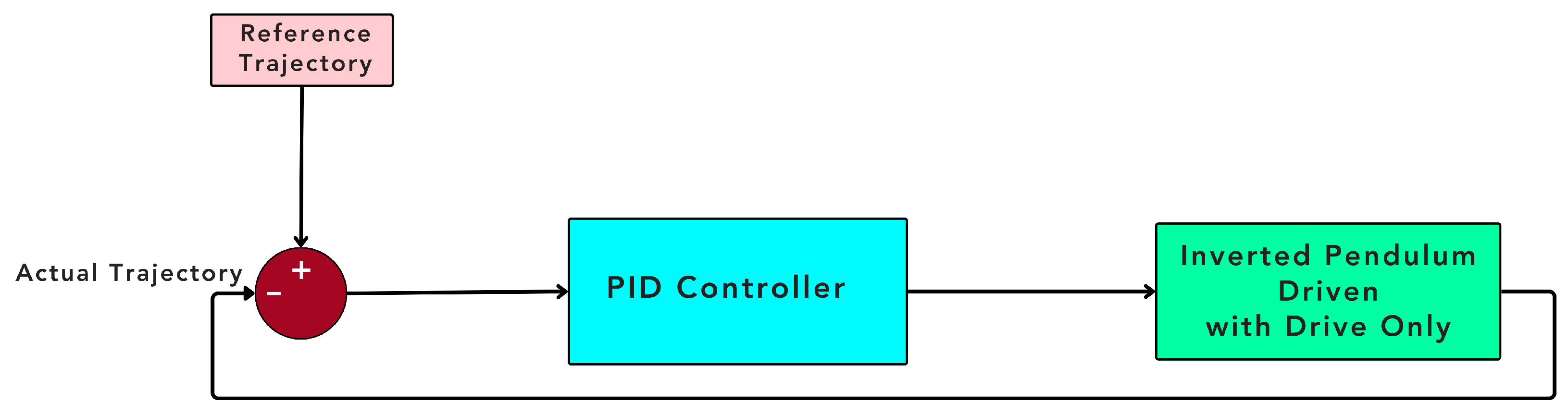
This system operates in a closed-loop mode, where feedback from sensors measuring the position of the pendulum is used to adjust the control voltages and maintain stability. The schematic diagrams of the control loops for the drive–anti-drive system and the single-drive system are shown in Figure 4 and Figure 5, respectively. The power ratio of the anti-drive to the drive is empirically calculated to be 3.4 for the case at hand.

Figure 5.
Schematic diagram of the single drive.
4. Results
A thorough comparison between the switched drive–anti-drive controller and the conventional system without anti-drive draws important conclusions. The target tracking of the inverted pendulum in the presence of known backlash was performed with a drive–anti-drive controller and also with only a conventional drive. The performance of the system was gauged by performance metrics that included the comparison of root mean square error, overshoots, peak time, and settling time.
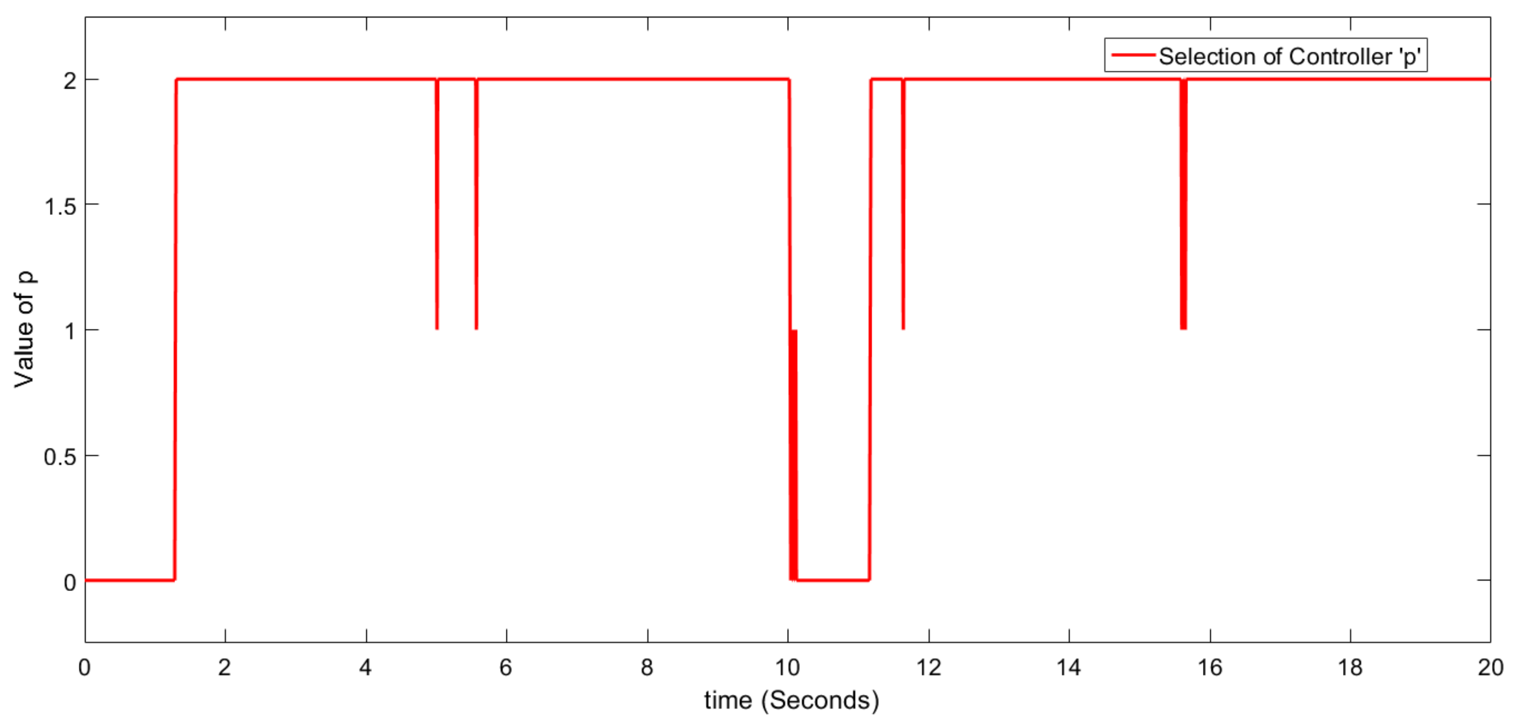
The switched-mode controller dynamically adjusts the assigned controller based on the value of p. It continuously monitors the pendulum states and responds to directional changes accordingly, as illustrated in Figure 6.
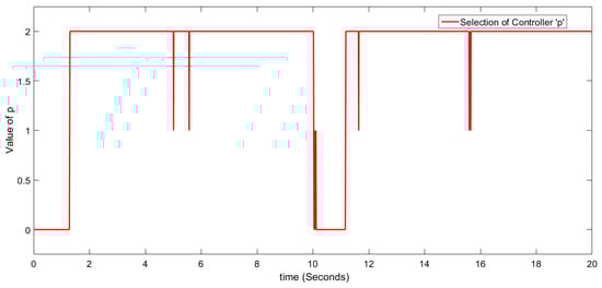
Figure 6.
Selection of the controller.
Here, three cases are used to discuss the performance of the system.
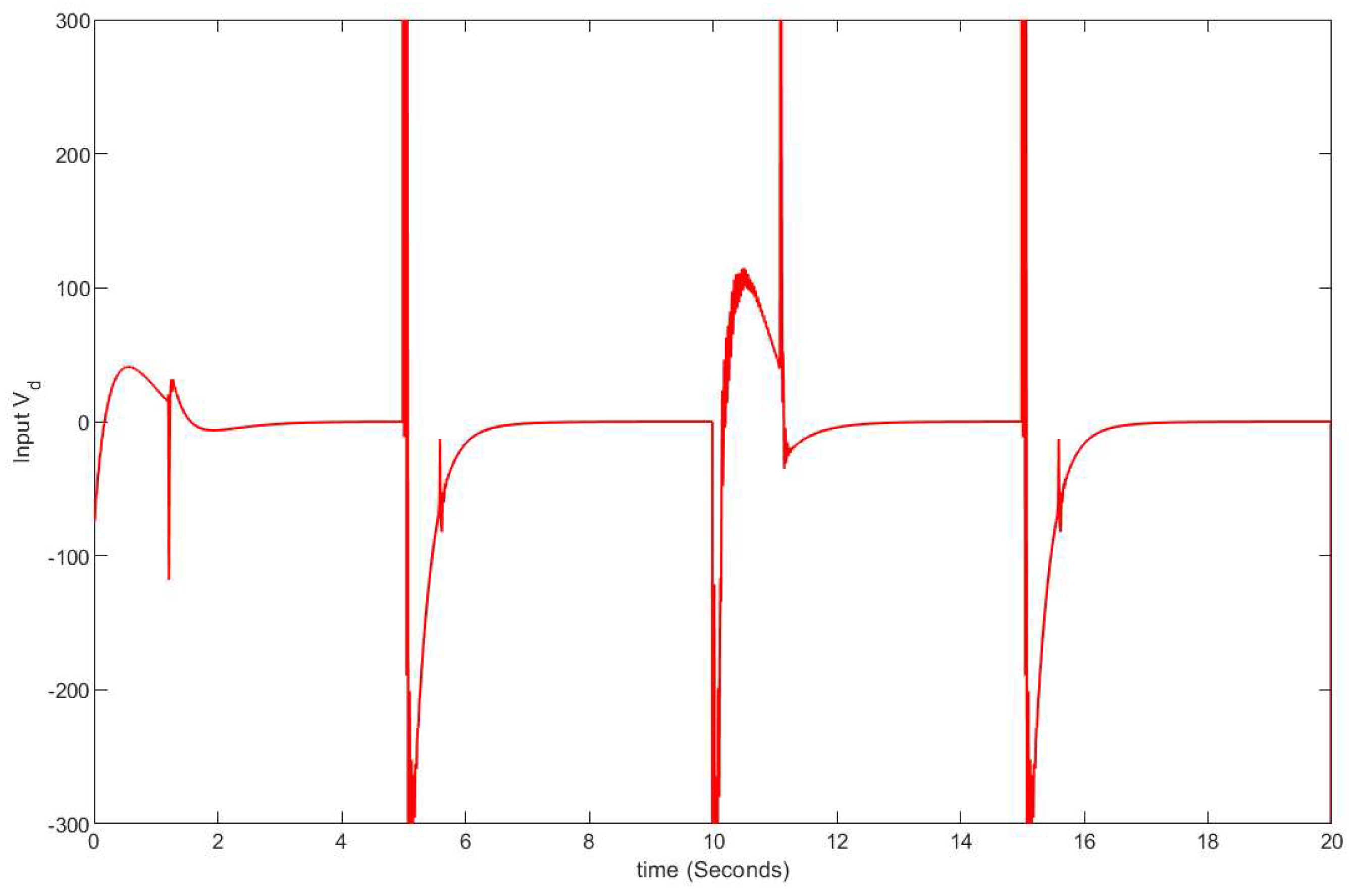
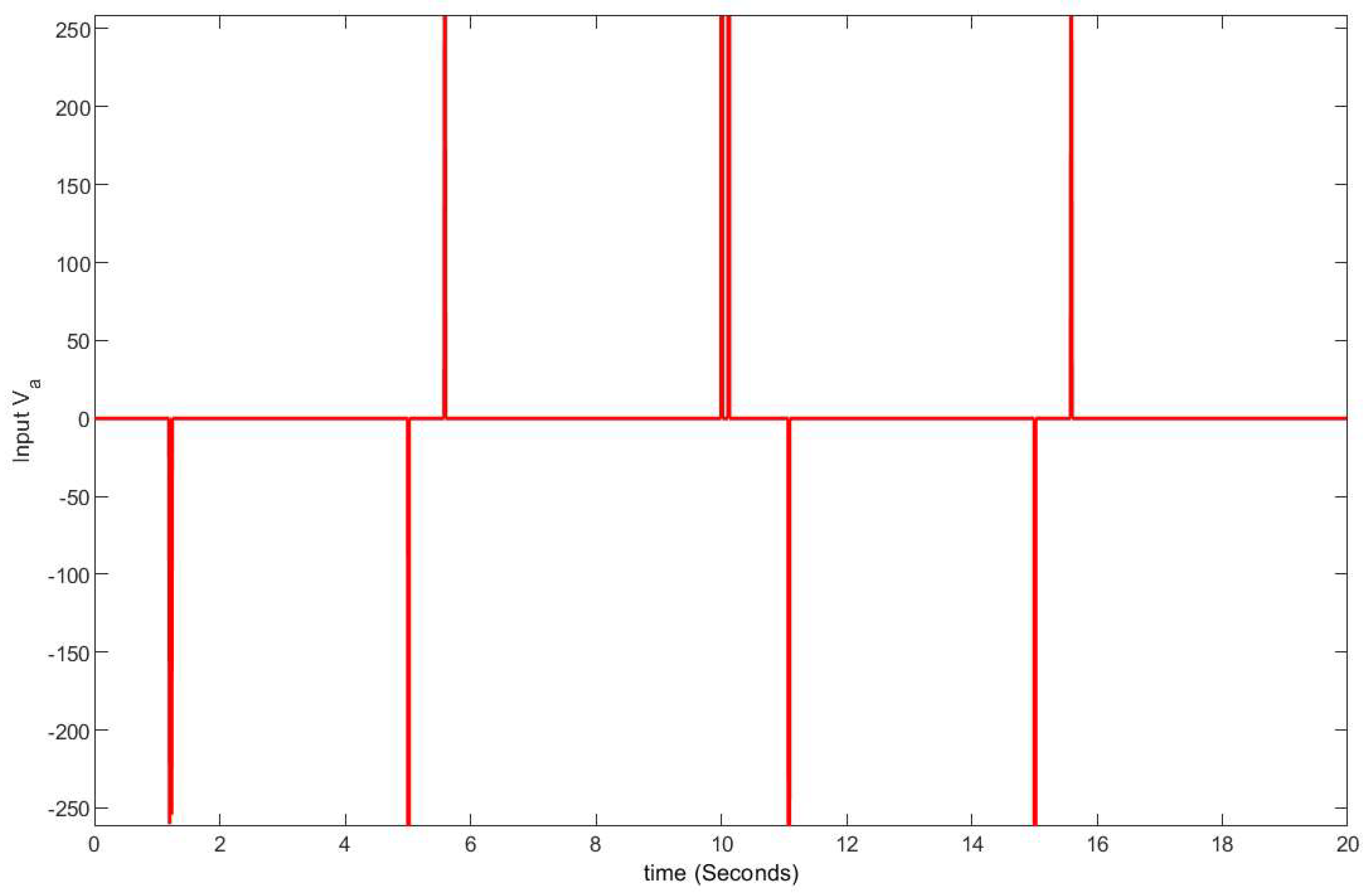
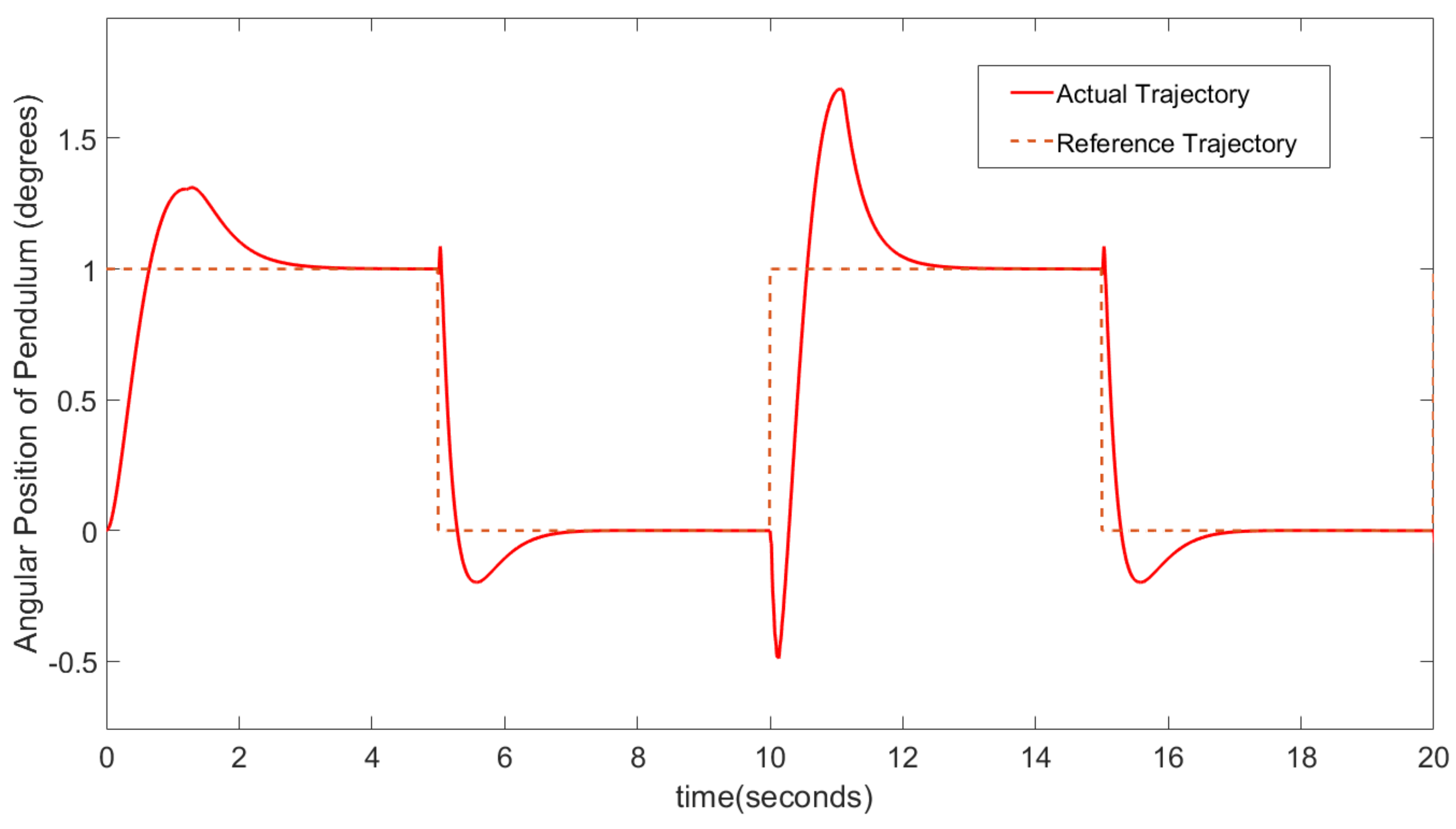
When , only the drive is used to track the reference trajectory. Controller 0 drives the driven motor. The control effort by the drive in a switched-mode controller is seen in Figure 7. Anti-drive is not active at that time. We can observe that, when the system changes direction at s, p progresses to 1. When , the anti-drive motor is actuated to compensate for backlash, which can be seen from the control effort made by the anti-drive, as shown in Figure 8. The scheme of transitions between the controllers is explained in Algorithm 1.The drive–anti-drive controller exhibits good performance in accurately tracking the reference trajectory, as shown in Figure 9. This switching controller has helped the system in achieving lower rise and settling times. The decrease in overshoot highlights the system’s improved stability, as it exhibits less oscillation around the target value in Figure 9.
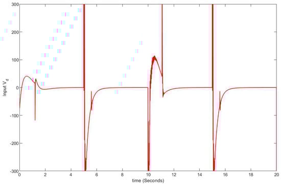
Figure 7.
Control effort by the drive in a switched-mode controller.
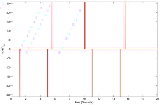
Figure 8.
Control effort by the anti-drive in a switched-mode controller.
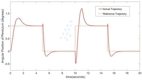
Figure 9.
Tracking output with drive–anti-drive.
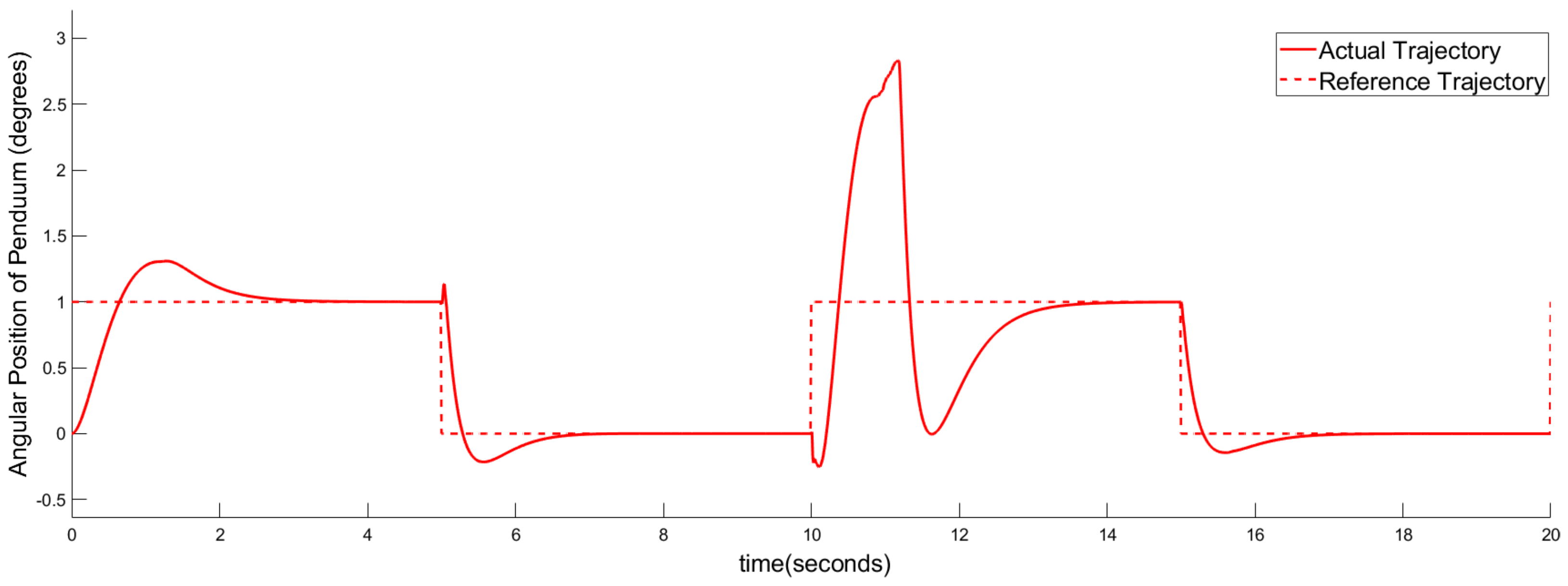
The analysis reveals a notable increase in overshoot when the system operates solely with drive control, especially during transitions into backlash mode, as depicted in Figure 10.
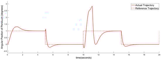
Figure 10.
Tracking output with drive only.
The performances of switched-mode drive–anti-drive and of drive-only are further gauged by root mean square error (RMSE), which is a robust measure of tracking accuracy. Mathematically, if y is the actual angular position of the pendulum, is the reference trajectory value, and n is the number of observations, the RMSE is given by
where represents the set of output samples from the numerical simulation. The RMSE deviation for tracking error with a single controller was determined to be 0.3591. However, with the implementation of the drive–anti-drive controller, the RMSE deviation for tracking error reduced to 0.28. This reduction in RMSE signifies a substantial enhancement in performance.
In essence, the presence of the switched drive–anti-drive controller significantly enhances the system’s ability to handle backlash-induced overshoots and effectively track the reference trajectory in lesser settling time, as shown in Table 5, thereby improving its overall performance compared to systems lacking such compensation mechanisms.
Table 5.
Performance metric comparison of the drive–anti-drive vs. drive-only systems.
These enhancements suggest that implementing the anti-drive mechanism results in a more agile and reliable drive system.
5. Discussions
The switched-mode drive–anti-drive’s improved performance is particularly beneficial in practical applications where quick response times and stability are critical, such as in precision manufacturing, robotics, and automated control systems [28,29]. By optimizing these performance aspects, the drive–anti-drive system can lead to higher productivity, reduced wear and tear on components, and more consistent operational outcomes. It showed superior stability and faster response times, efficiently returning the pendulum to its upright position, even under significant disturbances. However, this came at the cost of higher control effort, indicating more frequent and intense adjustments in the controller. In contrast, the single drive configuration demonstrated lower control effort, which could be advantageous for energy efficiency. However, it showed instability under higher disturbance scenarios and a slower response time in returning the pendulum to its upright position as discussed in the scenario when load is driven with single drive as shown in Figure 10.
This comparative analysis highlights that the drive–anti-drive configuration is ideal for scenarios requiring high precision and stability.
6. Conclusions
In this paper, we propose a drive–anti-drive control strategy together with a switched-mode controller to mitigate the adverse effects of backlash in a real-world application, i.e., an inverted pendulum. This approach demonstrates marked improvement in closed-loop tracking performance over the traditional single-drive control strategy. The proposed control strategy to mitigate backlash effects involves using a drive motor and an anti-drive motor. Three PID controllers were designed, and a switching strategy to select the appropriate control input depending on the mode was devised to actuate the drive and anti-drive motors. The performance of the closed-loop system, quantified by the root mean square error (RMSE), shows a significant enhancement in performance compared to the one using only a single drive. Future work will extend this approach for scenarios where the backlash parameters are (partially) unknown.
Author Contributions
Conceptualization, A.A.A., U.S.K. and A.U.A.; methodology, A.A.A., U.S.K. and A.U.A.; software, A.A.A., U.S.K. and A.U.A.; validation, A.A.A., U.S.K. and A.U.A.; formal analysis, A.A.A., U.S.K. and A.U.A.; investigation, A.A.A., U.S.K. and A.U.A.; writing—A.A.A.; draft preparation, A.A.A.; writing—review and editing, A.A.A., U.S.K., A.U.A. and A.H.; visualization, A.A.A., U.S.K. and A.U.A.; supervision, U.S.K. and A.H.; project administration, U.S.K. and A.H. All authors have read and agreed to the published version of the manuscript.
Funding
This research received no external funding.
Institutional Review Board Statement
Not applicable.
Informed Consent Statement
Not applicable.
Data Availability Statement
Conflicts of Interest
The authors declare no conflicts of interest.
Abbreviations
The following abbreviations are used in this manuscript:
| Torque produced by the primary and secondary motors, respectively | |
| Reaction torques produced by the the first and second gear | |
| Radius of gear 1 and gear 2, respectively | |
| Angular position of the inverted pendulum by the primary motor | |
| Angular velocity of the inverted pendulum by the primary motor | |
| l | Length of the inverted pendulum |
| Moment of inertia of the primary motor and secondary motor, respectively | |
| K | Material rigidity |
| C | Damping coefficient |
| Armature resistance of the drive and anti-drive, respectively | |
| Inductance of the drive and anti-drive, respectively | |
| Current of the drive and anti-drive, respectively | |
| Voltage applied to the drive and anti-drive, respectively | |
| Output of controllers 1, 2, and 3, respectively | |
| Drive and anti-drive controlled voltages |
References
- Bai, E.W. Identification of linear systems with hard input nonlinearities of known structure. IFAC Proc. Vol. 2002, 35, 97–102. [Google Scholar] [CrossRef]
- Barreiro, A.; Baños, A. Input-output stability of systems with backlash. Automatica 2006, 42, 1017–1024. [Google Scholar] [CrossRef]
- Hägglund, T. Automatic on-line estimation of backlash in control loops. J. Process Control 2007, 17, 489–499. [Google Scholar] [CrossRef]
- Vörös, J. Modeling and identification of systems with backlash. Automatica 2010, 46, 369–374. [Google Scholar] [CrossRef]
- Karim, A.; Lindner, P.; Verl, A. Control-based compensation of friction and backlash within rack-and-pinion drives. Prod. Eng. 2018, 12, 589–596. [Google Scholar] [CrossRef]
- Yi, Y.; Huang, K.; Xiong, Y.; Sang, M. Nonlinear dynamic modelling and analysis for a spur gear system with time-varying pressure angle and gear backlash. Mech. Syst. Signal Process. 2019, 132, 18–34. [Google Scholar] [CrossRef]
- Park, C.I. Dynamic behavior of the spur gear system with time varying stiffness by gear positions in the backlash. J. Mech. Sci. Technol. 2020, 34, 565–572. [Google Scholar] [CrossRef]
- Huo, X.; Ma, L.; Zhao, X.; Niu, B.; Zong, G. Observer-based adaptive fuzzy tracking control of MIMO switched nonlinear systems preceded by unknown backlash-like hysteresis. Inf. Sci. 2019, 490, 369–386. [Google Scholar] [CrossRef]
- Yamada, S.; Fujimoto, H. Precise joint torque control method for two-inertia system with backlash using load-side encoder. IEEJ J. Ind. Appl. 2019, 8, 75–83. [Google Scholar] [CrossRef]
- Zhao, H.; Wang, C. A new adaptive control of dual-motor driving servo system with backlash nonlinearity. Sādhanā 2018, 43, 155. [Google Scholar] [CrossRef]
- Ma, L.; Huo, X.; Zhao, X.; Niu, B.; Zong, G. Adaptive neural control for switched nonlinear systems with unknown backlash-like hysteresis and output dead-zone. Neurocomputing 2019, 357, 203–214. [Google Scholar] [CrossRef]
- Papageorgiou, D.; Blanke, M.; Niemann, H.H.; Richter, J.H. Robust Backlash Estimation for Industrial Drive-Train Systems—Theory and Validation. IEEE Trans. Control Syst. Technol. 2018, 27, 1847–1861. [Google Scholar] [CrossRef]
- Formentini, A.; Oliveri, A.; Marchesoni, M.; Storace, M. A Switched Predictive Controller for an Electrical Powertrain System with Backlash. IEEE Trans. Power Electron. 2016, 32, 4036–4047. [Google Scholar] [CrossRef]
- Rostiti, C.; Liu, Y.; Canova, M.; Stockar, S.; Chen, G.; Dourra, H.; Prucka, M. A Backlash Compensator for Drivability Improvement Via Real-Time Model Predictive Control. J. Dyn. Syst. Meas. Control. Trans. 2018, 140, 104501. [Google Scholar] [CrossRef]
- Liu, Y.J.; Tong, S. Adaptive fuzzy control for a class of nonlinear discrete-time systems with backlash. IEEE Trans. Fuzzy Syst. 2013, 22, 1359–1365. [Google Scholar] [CrossRef]
- Lai, G.; Liu, Z.; Zhang, Y.; Chen, C.L.P. Adaptive Fuzzy Tracking Control of Nonlinear Systems with Asymmetric Actuator Backlash Based on a New Smooth Inverse. IEEE Trans. Cybern. 2015, 46, 1250–1262. [Google Scholar] [CrossRef] [PubMed]
- Li, Y.; Tong, S. Adaptive Fuzzy Output-Feedback Stabilization Control for a Class of Switched Nonstrict-Feedback Nonlinear Systems. IEEE Trans. Cybern. 2016, 47, 1007–1016. [Google Scholar] [CrossRef] [PubMed]
- Lai, G.; Liu, Z.; Zhang, Y.; Chen, C.L.; Xie, S. Adaptive Inversion-Based Fuzzy Compensation Control of Uncertain Pure-Feedback Systems with Asymmetric Actuator Backlash. IEEE Trans. Fuzzy Syst. 2016, 25, 141–155. [Google Scholar] [CrossRef]
- Wu, J.; Li, J.; Chen, W. Practical adaptive fuzzy tracking control for a class of perturbed nonlinear systems with backlash nonlinearity. Inf. Sci. 2017, 420, 517–531. [Google Scholar] [CrossRef]
- Abhari, S.A.; Hashemzadeh, F.; Baradarannia, M.; Kharrati, H. An adaptive robust control scheme for robot manipulators with unknown backlash nonlinearity in gears. Trans. Inst. Meas. Control 2018, 41, 2789–2802. [Google Scholar] [CrossRef]
- He, W.; He, X.; Zou, M.; Li, H. PDE Model-Based Boundary Control Design for a Flexible Robotic Manipulator with Input Backlash. IEEE Trans. Control Syst. Technol. 2018, 27, 790–797. [Google Scholar] [CrossRef]
- Wang, A.; Zeng, Q.; Ma, L.; Wang, H. Adaptive Backlash Compensation Method Based on Touch State Observation for a Solid Ducted Rocket. Int. J. Aerosp. Eng. 2020, 2020, 6698158. [Google Scholar] [CrossRef]
- Sun, G.; Zhao, J.; Chen, Q. Observer-based compensation control of servo systems with backlash. Asian J. Control 2021, 23, 499–512. [Google Scholar] [CrossRef]
- Sun, G.; Xu, Y.; Wang, Y.; Wang, G. Variable gain switching exact differential observer-based compensation control for servo system with backlash. IET Control Theory Appl. 2021, 15, 1789–1803. [Google Scholar] [CrossRef]
- Robertz, S.G.; Halt, L.; Kelkar, S.; Nilsson, K.; Robertsson, A.; Schär, D.; Schiffer, J. Precise robot motions using dual motor control. In Proceedings of the 2010 IEEE International Conference on Robotics and Automation, Anchorage, AK, USA, 3–7 May 2010; pp. 5613–5620. [Google Scholar] [CrossRef]
- Haider, Z.; Habib, F.; Mukhtar, M.H.; Munawar, K. Design, Control and Implementation of 2-DOF Motion Tracking Platform using Drive-Anti Drive Mechanism for Compensation of Backlash. In Proceedings of the 2007 International Workshop on Robotic and Sensors Environments, Ottawa, ON, Canada, 12–13 October 2007; pp. 1–6. [Google Scholar] [CrossRef]
- Silik, Y.; Yaman, U. Control of Rotary Inverted Pendulum by Using On–Off Type of Cold Gas Thrusters. Actuators 2020, 9, 95. [Google Scholar] [CrossRef]
- Yang, J.H.; Fu, L.C. Nonlinear Adaptive Control for Manipulator System with Gear Backlash. In Proceedings of the 35th IEEE Conference on Decision and Control, Kobe, Japan, 13 December 1996. [Google Scholar]
- Sigron, P.; Aschwanden, I.; Bambach, M. Compensation of Geometric, Backlash, and Thermal Drift Errors Using a Universal Industrial Robot Model. IEEE Trans. Autom. Sci. Eng. 2023, 1–13. [Google Scholar] [CrossRef]


Disclaimer/Publisher’s Note: The statements, opinions and data contained in all publications are solely those of the individual author(s) and contributor(s) and not of MDPI and/or the editor(s). MDPI and/or the editor(s) disclaim responsibility for any injury to people or property resulting from any ideas, methods, instructions or products referred to in the content. |
© 2024 by the authors. Licensee MDPI, Basel, Switzerland. This article is an open access article distributed under the terms and conditions of the Creative Commons Attribution (CC BY) license (https://creativecommons.org/licenses/by/4.0/).