Article

An Attempt to Establish a Mathematical Model for an Unconventional Worm Gear with Bearings

1
Mechanical Systems Engineering Department, Faculty of Industrial Engineering, Robotics and Production Management, Technical University of Cluj-Napoca, 28 Memorandumului Street, 400114 Cluj-Napoca, Romania
2
Computer Department, Technical University of Cluj-Napoca, 28 Memorandumului Street, 400114 Cluj-Napoca, Romania
3
Materials Science and Engineering Department, Faculty of Materials and Environmental Engineering, Technical University of Cluj-Napoca, 28 Memorandumului Street, 400114 Cluj-Napoca, Romania
*
Authors to whom correspondence should be addressed.
Appl. Sci. 2024, 14(23), 10833; https://doi.org/10.3390/app142310833
Submission received: 14 October 2024 / Revised: 15 November 2024 / Accepted: 20 November 2024 / Published: 22 November 2024
(This article belongs to the Special Issue Machine Tools, Advanced Manufacturing and Precision Manufacturing)

Abstract

:
The aim of this paper is to develop a mathematical model for an unconventional worm gear consisting of a globoid worm and a worm wheel where the teeth are bearings. Using rolling elements such the teeth of the worm wheel (ball bearings) transforms the sliding friction to rolling friction during the process of worm gear meshing, improving power. The geometry of the component elements of the gear is analyzed in correlation with its kinematics. After the creation of the mathematical model, it is validated both analytically (through complex graphic representations) and experimentally (by creating, for a particular case, the 3D model and the concrete physical model (prototype) of the gear through 3D printing).

1. Introduction

To fulfill the increasing demands for a high gear transmission ratio using a single stage (up to 80) with compact gear dimensions, high load-carrying capacity, and smoothness in operation, etc.—needed for lifting-and-shifting machines in the aerospace industry and modern manufacturing processes—various worm drive types are used. These space-saving gearings, depending on the external surface shape of the worm and wheel, can be cylindrical (with a cylindrical worm known as a single-enveloping worm being the most commonly used [1]); globoid, known as the TA or Hindley worm drive or double-enveloping worm (DEW) (in this case, either the worm is globoid [2] or both the worm and wheel are globoid); or special (where the worm has a conical shape, called a spiroid [1], and the other element is a face-type gear) [3].
Until now, worm drives have been the subject of many researchers’ studies. In the technical literature, there are significant publications about mathematical modeling methods, various surface analyses, research regarding new types of worm gears, and manufacturing processes.
A summary of the development phases of these worm gearings is presented in [4]. Litvin and Fuentes [5] described a study on the theory of gearing. Ninacs, Cristea, and Haragâș [6] presented a detailed kinematic and functional analysis of a double-envelope worm gear. Practical design aspects are detailed [7]. Zhao, Huai, and Zhang [8] proposed a new meshing theory for a globoid worm gear considering some modifications regarding the following parameters: center distance, transmitting ratio, and the height of the cutter frame. Xu, Qin, and Shi [9] suggested new research on worm gear drives based on the practical manufacturing process known as the direct digital modeling method (DDMM). They presented a detailed discussion on the misalignment errors and contact deformations in the contact zone and concluded that the proposed design solution is characterized by reduced misalignment and transmission errors. Polowniak, Sobolak, and Marciniec [10] created an algorithm for generating the helix of a double-enveloping worm gear. They generated CAD models, which were used for FEM analysis to manufacture real prototypes employing additive manufacturing processes. Zhao and Zang [11] presented a study regarding the curvature analysis for the helicoidal surface of a modified TA worm. However, the author of this study did not investigate the meshing process. A meshing theory for the TA worm gearing is described [12]. The performance of the studied worm gear set is considerably favorable over the other types of conical worm drive. A discussion about a new type of spiroid gear set is detailed [12]. Regarding the manufacturing process, the following studies were conducted. Andrianto, Wu, and Arifin [13] developed a new method for machining double-enveloping worms (DEWs). Firstly, they carried out a virtual simulation of the cutting process, followed by an experimental test of a worm gear set. In their research, Rui et al. [14] presented a land surface cutting Hob’s design for increasing the machining tool’s service life. Lei et al. [15] proposed a five-axis tool path for worm gear flank milling. This machining process is then compared to the conventional end milling processes. The method studied offers high process efficiency and surface quality. Dong et al. [16] described a method of rough turning for the toroidal worm that permits higher-efficiency manufacturing. Chen Y. et al. [17] introduced a new type of worm drive consisting of a planar internal gear and a crown worm. The components were machined and then the obtained prototype was assembled and subject to a running test, in which the efficiency and the oil temperature were checked.
Double-enveloping worm drives, as previously mentioned, have applications in various domains considering their advantages (as compared to the other worm gear types) such as higher efficiency (because of more favorable functioning conditions [10]), smoothness, and silence in operation, high load capacity due to a higher contact ratio, etc. However, this type of worm gear is sensitive to tolerance, needs accurate alignment, and is characterized by high wear and a tendency to seize [1]. Another significant aspect is the backlash, which has a major impact on smooth operation and over-transmission errors.
To overcome these disadvantages of the globoid worm gear drive, a new roller enveloping toroidal worm gear was proposed. This design solution consists of a worm wheel in which the teeth are replaced with deep groove ball bearings. Using rolling elements turns the sliding friction into rolling friction during the process of worm gear meshing, which eliminates the backlash [18] (when they are used custom-designed bearings) and conducts higher gear efficiency. In [18], Deng et al. investigated a new single-roller enveloping hourglass worm gear. They proposed a design to eliminate the backlash in mating gear transmission. A parametric study was conducted to analyze the influence of some design variables, i.e., the center distance, roller radius, transmission ratio, and radius of the base circle over the gear set characteristics. An analysis of the dynamic behavior of these gears was carried out in [19,20,21]. The 3D-generated CAD model was then compared with the calculated one. A very good match was found. Another interesting study about these new gearings is described in [9]. It presented a methodology for thermal power calculation.
What we pursue as a priority in this paper is to obtain a general mathematical model of the non-conventional worm gear with bearings that is clear, coherent, demonstrable, and easy to apply for particular situations, an essential aspect for the realization of both 3D and physical models. The objective of the paper is to reduce the friction force in the worm-roller gear using the rolling force of the bearing (tooth) on the surface of a helical worm. In this paper, a mathematical model of a double-deep groove ball-bearing enveloping worm gear drive is presented. A total of 36 bearings were used (each new worm wheel tooth was composed of two bearings), replacing the worm wheel teeth. Here, a mathematical model is first formulated, followed by graphical validation of the globoid helix. The Wolfram 14.1, online version [22] program was utilized to generate globoid helices.

2. Materials and Methods

The “classic” globoid worm gear (Figure 1) consists of a globoid worm and a similar globoid worm wheel [4]. The globoid worm is one in which the helix coils around a toroidal reference surface. Kinematic and functional analyzes of this type of gear are carried out in works [1,10,13,16,23,24,25]. Constructive design aspects are presented in [4]. The materials used include hardened steels (generally case-hardening steels) for the worm and an anti-friction material (tin bronze or aluminum, nodular graphite cast iron or gray) for the worm wheel.
The advantages of this gear include its quiet operation, high degree of coverage, and high bearing capacity (smaller gauge at the same power to be transmitted).
The main disadvantage is that of frictional losses (due to the sliding friction between the worm turn and the worm gear teeth). As the friction is intense, there is a significant release of heat and, implicitly, the transmission efficiency will be reduced.
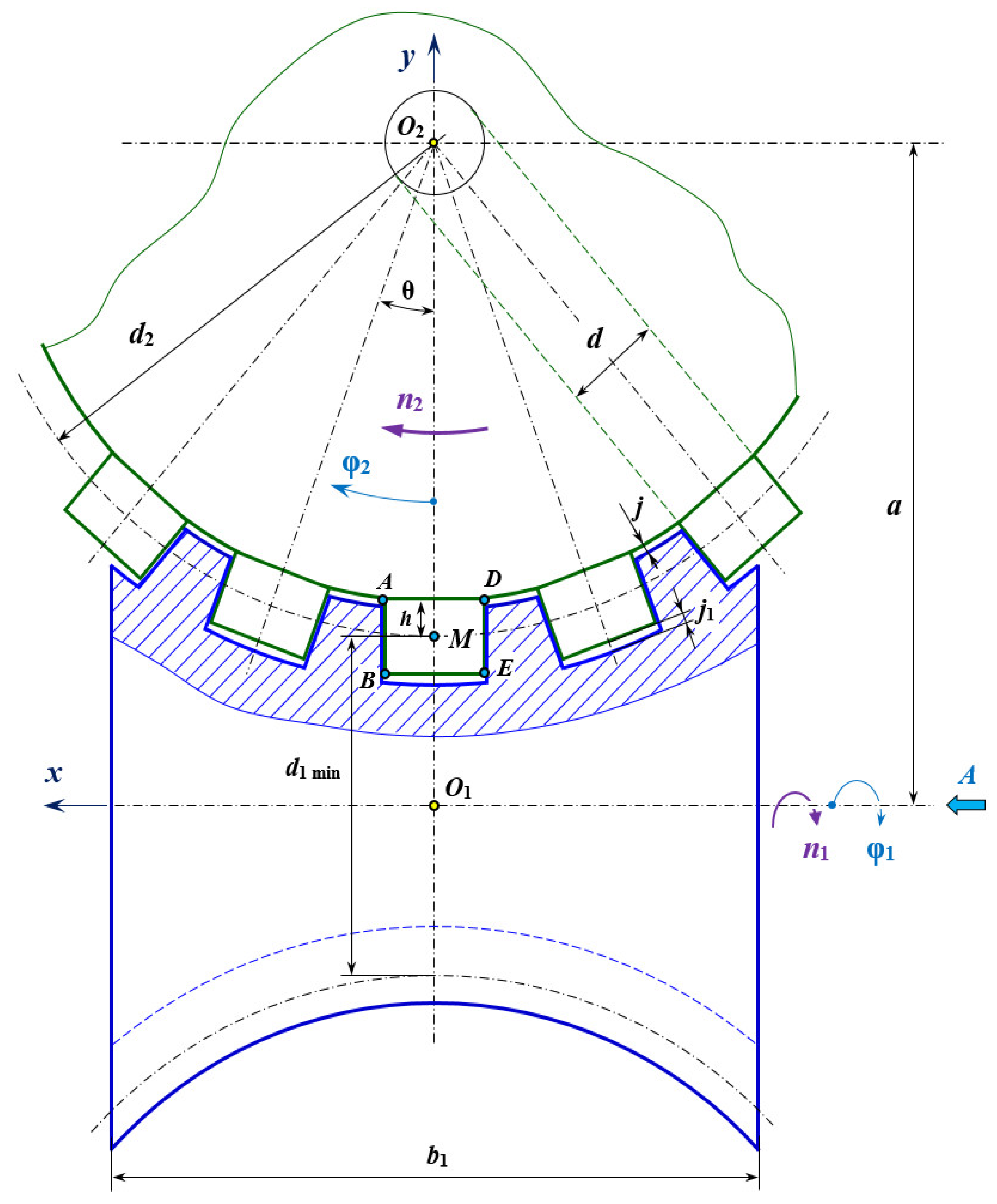
Another disadvantage is that of positioning accuracy because there is quite a large interplay (denoted j in Figure 1) between the elements in contact.
To reduce the effects of these disadvantages, several variants of “unconventional” gears have been proposed in which the sliding friction is replaced by rolling friction (the rolling friction coefficient is about ten times lower than the sliding friction coefficient). Also, the play in the gear can be precisely controlled; even pre-tensioning can be achieved.
Such a construction is the worm gear with bearings (Figure 2), which is the subject of study in this paper.
In this gear, the shape of the worm does not change, but the driven wheel will have radial bearings instead of teeth. The contact between the worm coil and the bearings is a linear contact (Hertz contact theory). The bearings will rotate around their own axis during operation. By changing the pitch of the spiral of the auger, the contact between its flanks and the bearings will be in different directions (Figure 2), which leads to the cancellation of the play between the elements of the gear components.
Various studies on specific aspects of this gear can be found in works [2,3,4,5,6,18,19,26,27,28,29,30,31,32,33,34,35,36,37,38,39,40,41]. In these articles, theoretical and experimental research, 3D modeling, finite element analysis, and research on concrete physical models are presented.
The mathematical model of this type of gear, however, is treated in a cursory manner. Rather, the defining equations seem to be obtained after the model generation and not the other way around, as would normally be the case.

2.1. Geometry of the Unconventional Worm Gear with Bearings, Kinematic Analysis, and Mathematical Model Formulation

The main geometric elements of the gear are shown in Figure 3. In the axial section, the flanks of the spiral of the worm are rectilinear and tangent to the profiling circle (with the center in O2 and diameter d, equal to the outer diameter of the bearing), which is concentric with the worm wheel. The inclination of the helix profile will be equal to the angular pitch θ between the rollers of the worm wheel.
Consider point M positioned in the center of the roller (bearing) and points A, B, D and E at its ends. The displacement of the lines AB and DE in the O1xvz system (related to the worm gear) results in the generation of the flanks of the spiral (Figure 3).
The equations of point M related to the worm wheel (system O1xyz) are:
{ x = d 2 2 sin φ 2 y = ( a d 2 2 ) + d 2 2 ( 1 cos φ 2 ) z = 0 { x = d 2 2 sin φ 2 y = a d 2 2 cos φ 2 z = 0
Relative to the driven wheel, the trajectory of point M is an arc of a circle. The position equations of point M related to the worm (system O1xyz) are:
{ x = d 2 2 sin φ 2 y = [ ( a d 2 2 ) + d 2 2 ( 1 cos φ 2 ) ] cos φ 1 z = [ ( a d 2 2 ) + d 2 2 ( 1 cos φ 2 ) ] sin φ 1 { x = d 2 2 sin φ 2 y = ( a d 2 2 cos φ 2 ) cos φ 1 z = ( a d 2 2 cos φ 2 ) sin φ 1
where
  • d2 is the worm wheel pitch diameter, mm;
  • a represents the center distance, mm;
  • φ1 is the angle of the position for the worm wheel, ° (degrees);
  • φ2 is the angle of the position for the worm wheel, ° (degrees).
φ 1 = u 12 φ 2
where
  • u12 represents the gear ratio
u 12 = z 2 z 1 = n 1 n 2
where
  • z 2 is the worm wheel number of radial ball bearings, i.e., the number of teeth (in a classic worm gearing);
  • z 1 represents the thread number of the worm;
  • n 1 and n 2 represent the rotational speed of the worm and wheel, respectively.
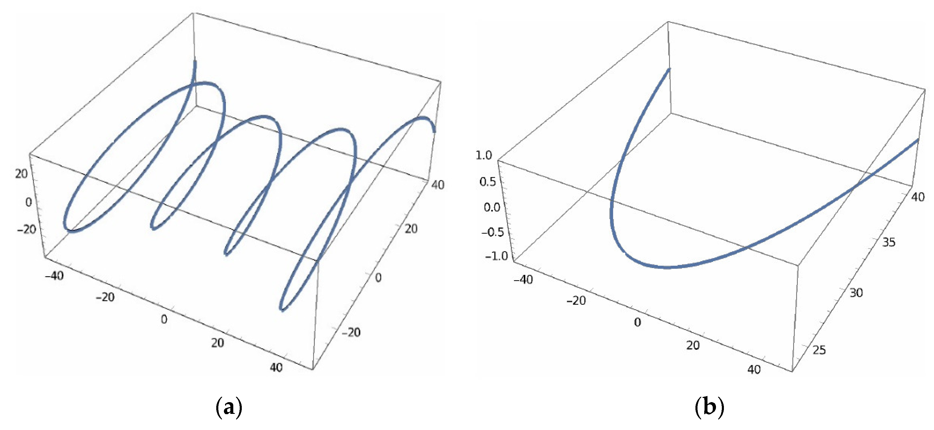
Relative to the worm, the trajectory of the M point is a helix wound on a toroidal surface (an inner circular torus).
Starting from Equation (2) of point M, the position equations of characteristic points A, B, D, and E (related to the coordinate system O1xyz) are shown:
Equations of point A (system O1xyz) are as follows:
{ x = d 2 cos φ 2 + ( d 2 2 h ) sin φ 2 y = [ a + d 2 sin φ 2 ( d 2 2 h ) cos φ 2 ] cos φ 1 z = [ a + d 2 sin φ 2 ( d 2 2 h ) cos φ 2 ] sin φ 1
where
  • d is the outer diameter of the bearing.
h = B r 2
where
  • B r is the bearing width.
Equations of point B (system O1xyz) are as follows:
{ x = d 2 cos φ 2 + ( d 2 2 + h ) sin φ 2 y = [ a + d 2 sin φ 2 ( d 2 2 + h ) cos φ 2 ] cos φ 1 z = [ a + d 2 sin φ 2 ( d 2 2 + h ) cos φ 2 ] sin φ 1
The parametric equations of the line AB (O1xyz system) are as follows:
{ x cos φ 2 cos φ 1 + y sin φ 2 [ a sin φ 2 + d 2 ] cos φ 1 = 0 y sin φ 1 + z cos φ 1 = 0
For point D, the equations are:
{ x = d 2 cos φ 2 + ( d 2 2 h ) sin φ 2 y = [ a d 2 sin φ 2 ( d 2 2 h ) cos φ 2 ] cos φ 1 z = [ a d 2 sin φ 2 ( d 2 2 h ) cos φ 2 ] sin φ 1
For point E, the equations are:
{ x = d 2 cos φ 2 + ( d 2 2 + h ) sin φ 2 y = [ a d 2 sin φ 2 ( d 2 2 + h ) cos φ 2 ] cos φ 1 z = [ a d 2 sin φ 2 ( d 2 2 + h ) cos φ 2 ] sin φ 1
The parametric equations of the line DE (O1xyz system) are as follows:
{ x cos φ 2 cos φ 1 + y sin φ 2 [ a sin φ 2 d 2 ] cos φ 1 = 0 y sin φ 1 + z cos φ 1 = 0
The surfaces described by lines AB and DE in the O1xyz system (parametric Equations (8) and (11)) materialize the surfaces of the flanks of the spiral of the worm (as will be explained in the next subsection).
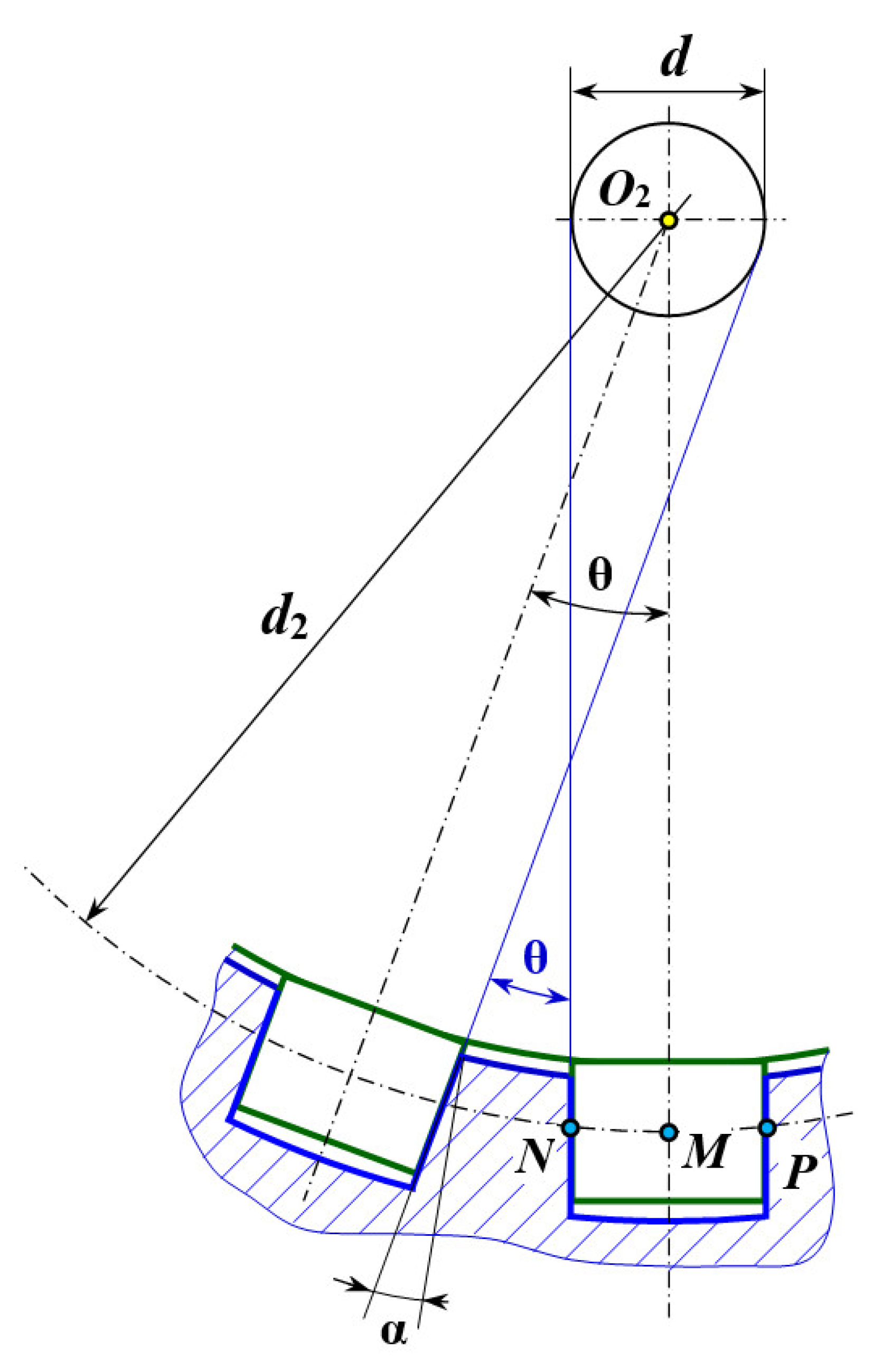
The profile of the worm’s spiral in its axial plane will be linear. The inclination of the profile of the spiral will be equal to the angular pitch θ between the driven wheel rollers (Figure 4).
θ = 2 π z 2   [ rad ]
The inclination of the flank of the worm is as follows:
α = θ 2   [ rad ]
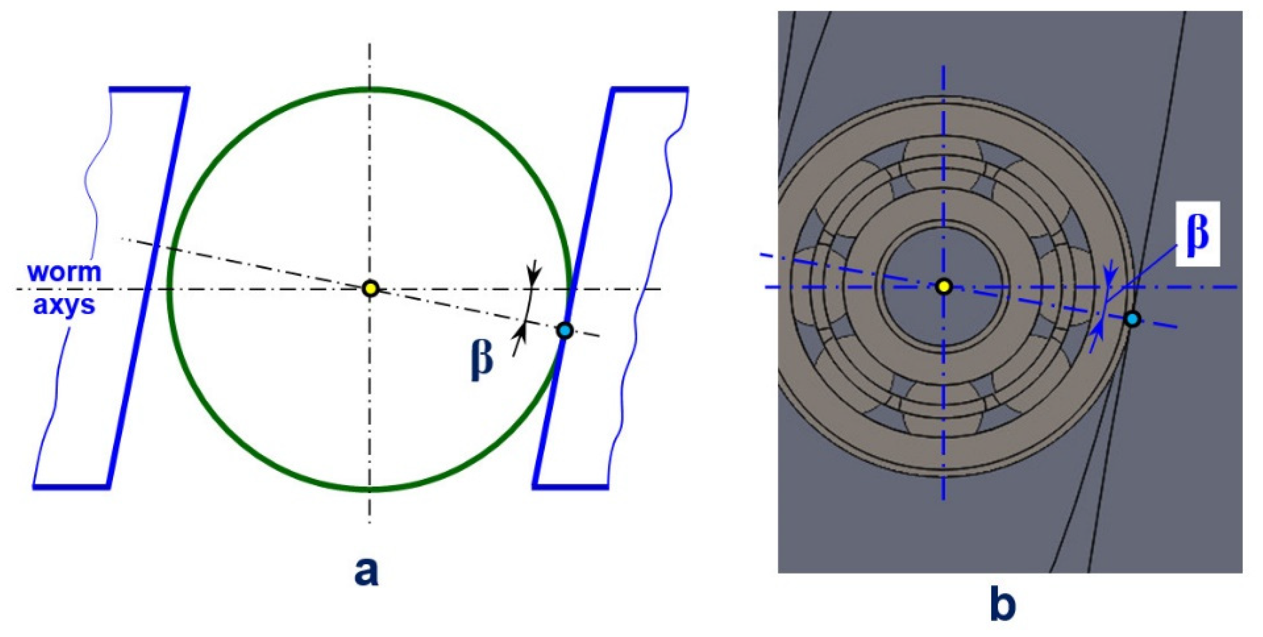
The contact between the flank of the auger spiral and the rollers (bearings) is shown in Figure 5. The plane in which the point of contact is located makes an angle β, equal to the angle of inclination of the spiral helix on the splitting diameter, with the frontal median plane of the wheel (which also contains the axis of the auger). This angle is variable with a maximum value for d1min and smaller values towards the ends.
In the axial section of the worm, the distance between the flanks is:
d s = d cos β
This must be taken into account when machining the worm. Thus, the diameter of the machining tool (finger cutter) must be larger than ds calculated with the minimum value of β.
The angle β can be calculated from the velocity plane (Figure 6).
tan β = v 2 v 1 β = arctan ( v 2 v 1 )
where
  • v2 is the peripheral speed of the driven wheel (constant).
  • v1 is the peripheral speed of the worm (variable).
v 1 = π d 1 n 1 60 1000   [ m / s ]
v 2 = π d 2 n 2 60 1000   [ m / s ]
Substituting relations (16) and (17) into relation (15) and taking into account relation (4) gives:
β = arctan ( d 2 u 12 d 1 )
The worm splitting diameter d1 is variable, its minimum value being d1min.
d 1 = d 1 min + d 2 ( 1 cos φ 2 )
d 1 min = 2 a d 2
Finally:
β = arctan [ d 2 u 12 ( 2 a d 2 cos φ 2 ) ]
Rolling speed of the bearings (rollers):
v r = v 1 cos β   [ m / s ]
Speed of the bearings (rollers):
n r = 60000 v r π d   [ rpm ]
The common point of the rolling surfaces is the common normal line, where the displacement occurs in a perpendicular tangent plane. The bearings move in the direction of the tangent of the reference helix line, which means that the generatrix of the bearing is in contact with the helicoid surface in front of the axis section of the worm. The contact generatrix of the bearing is a straight line that skews from the worm axis, so they are not coplanar.

2.2. Analytic Validation of the 3D Model

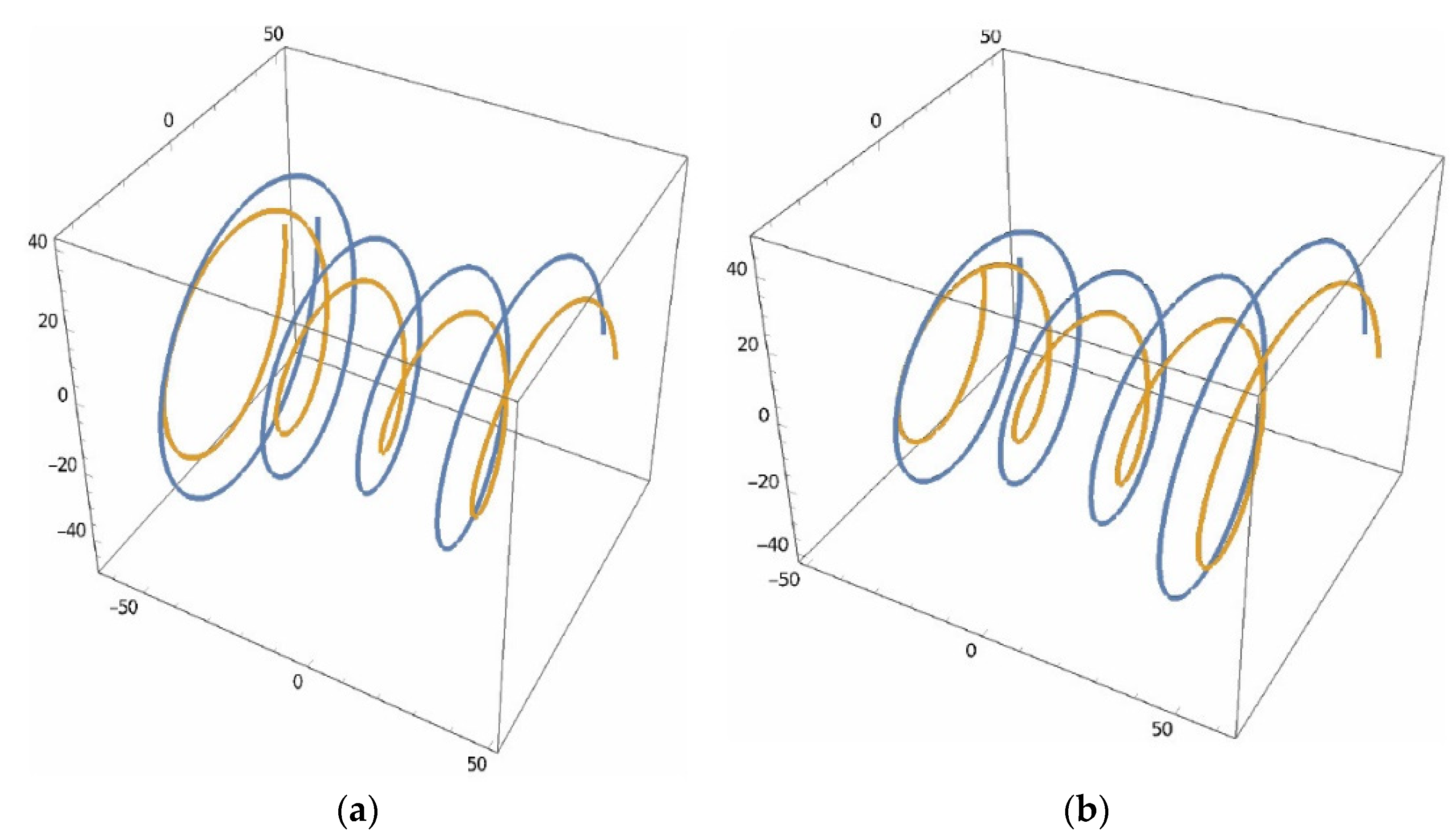
For the graphic representation of the previously determined equations, a particular case was considered, for which the following values were selected: a = 100 mm; d2 = 154 mm; φ2 = −40 … +40°; z1 = 1; z2 = 18; d = 16 mm; Br = 10 mm. The Wolfram [20] program was used to plot the graphs and validate the above equations. The obtained results are presented in Figure 7, Figure 8, Figure 9, Figure 10 and Figure 11.
The trajectory of point M relative to the worm (O1xyz system) is obviously a helix wound on a toroidal surface and relative to the driven wheel is an arc of a circle (which appears distorted due to perspective) (Figure 5).
The graphs of points A, B, D, and E follow the same pattern, with the gap due to the positioning of the points in relation to point M. The fact that their trajectories are correct is confirmed by the practical realization of the 3D model of the worm (Figure 6).
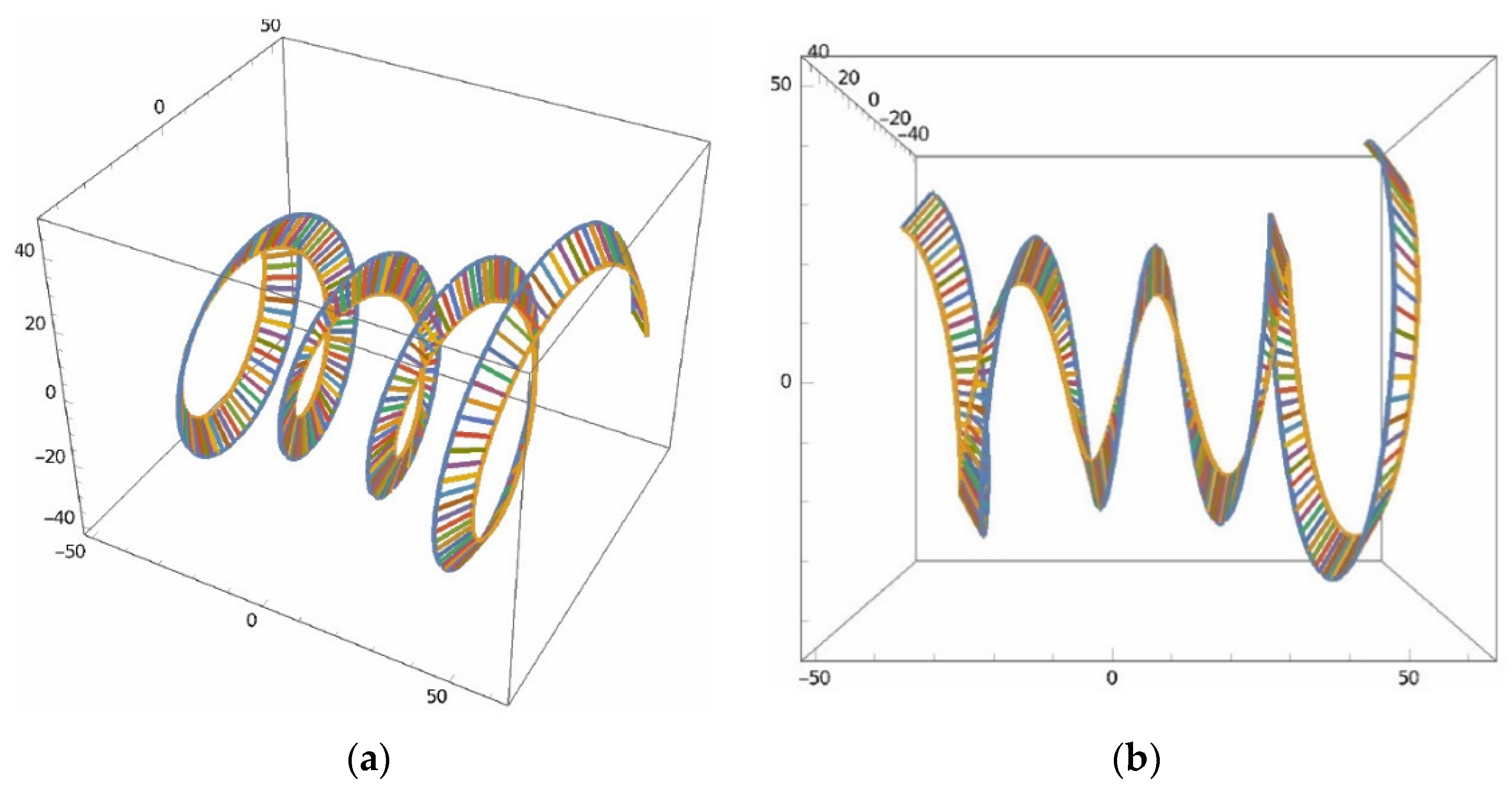
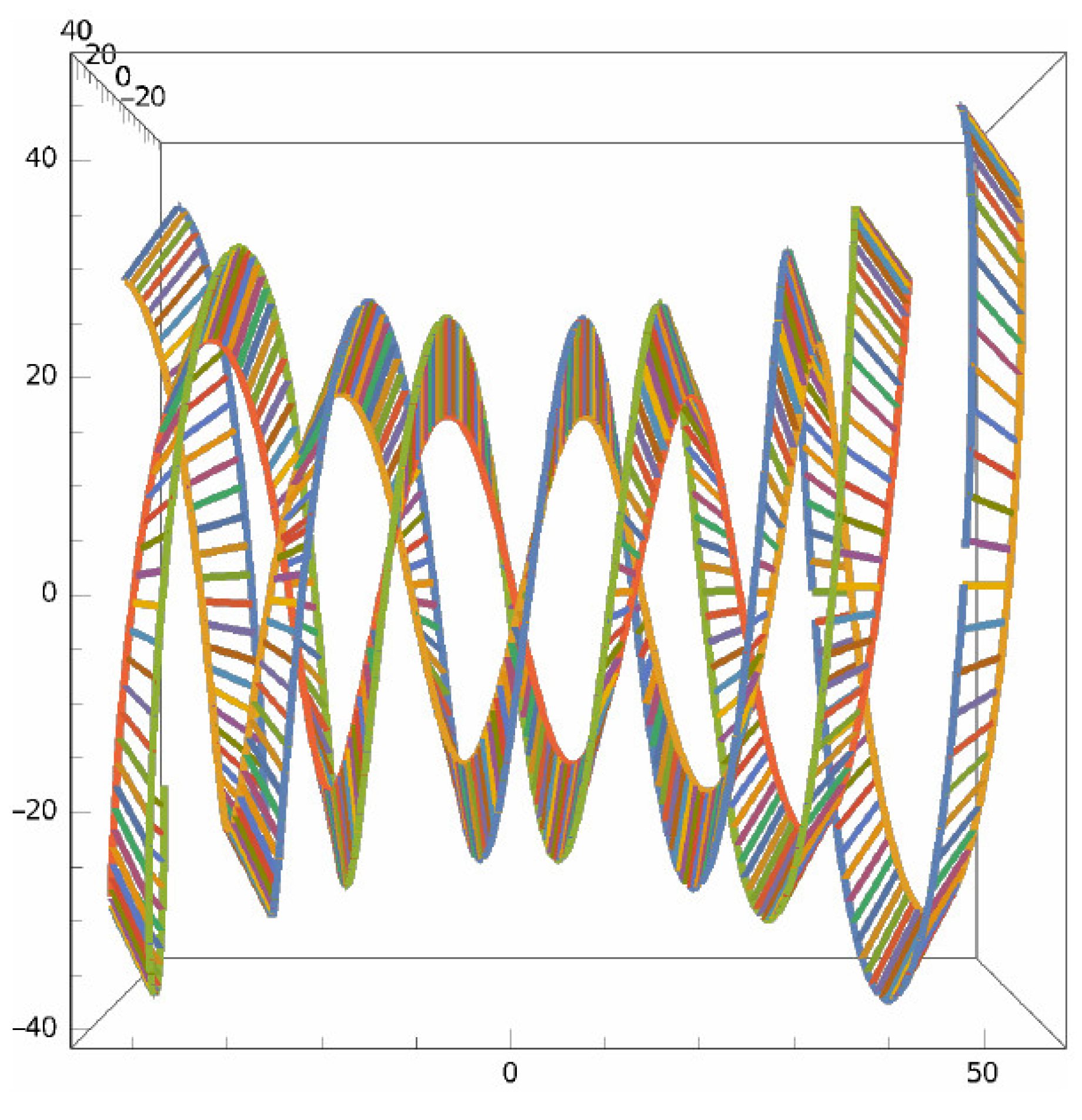
Lines AB and DE each generate one flank of the worm spiral (Figure 9 and Figure 10), their combination leading to the realization of the functional surfaces of the globoid spiral (Figure 11). The obtained results resemble that of a worm.
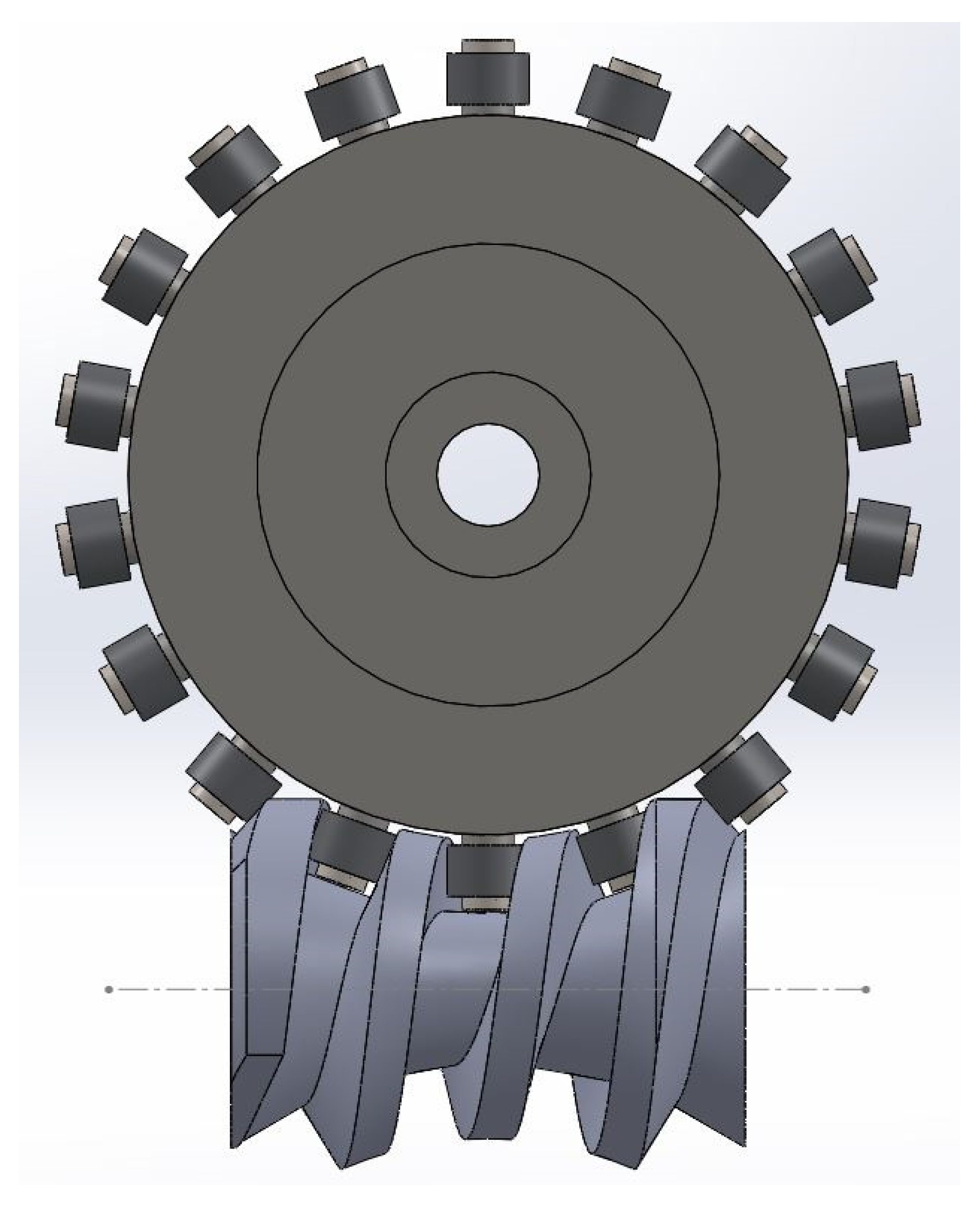
To create the 3D model of the worm, Equations (8) and (11) were used to generate the helices along which the profile of the worm’s spiral is generated (Figure 12). It can be seen that the propellers are tangent to the edges of the wheel rollers (bearings), which confirms that the mathematical model is correct. A 3D model of the worm (made in Solid Works) is presented in Figure 13, and that of the gear is shown in Figure 14.
At this moment, when the mathematical model of the worm gearing’s geometry is validated, the authors generate 3D models of the worm and worm wheel in SolidWorks to obtain .stl files necessary for achieving a 3D prototype of the worm gearing. Figure 12 shows the prototype of the globoid worm gear obtained employing 3D printing additive manufacturing.

3. Results

Experimental Validation of the Physical Model

For the experimental validation of the mathematical model, the physical model of the mechanism was made. The worm (Figure 15), driven wheel body, and worm bearings were made from PLA on a Creatbot DX Plus 3D printer. Two 625 series bearings were used for each “tooth” of the driven wheel. The dimensions of the gear elements are those used in the creation of the 3D model. Even if the dimensional accuracy is not at the same level as a machined part, it is sufficient for preliminary checks.
The physical model (Figure 16) works, and the gearing is correct.
Other constructive, kinematic, and even dynamic aspects can be studied on it, and various tests and trials can be carried out.
The accuracy of the presented theoretical model as well as the numerical analysis is therefore verified by making the 3D model and assembling it in a perfectly functional worm gear.

4. Conclusions

A mathematical model consisting of a non-conventional worm gear is presented in this study. The main aim of the paper was to develop a mathematical model for the non-conventional worm gear that is simple and easy to implement in practice but, at the same time, correct. The main problem was given by the globoid shape of the worm and the fact that the profile of the gap between the turns are rectangular, and this profile was found in the median frontal plane of the wheel, a plane that also contains the axis of the worm. Any machine on a CNC machine can be easily programmed taking these aspects into account.
The contact between the worm coil and the rollers is a linear Hertzian contact, and the relative motion is a rolling one. Due to this fact, the efficiency of such a transmission is obviously much higher than that of classic globoid gear: the friction force caused by the rolling of the bearing on the surface of the worm is lower.
The contact generatrix of the bearing is a straight line that skews from the worm axis, so they are not coplanar.
A finite element analysis of the stresses to which the active elements of the gear (the spiral of the worm and the rollers) are subjected can be performed based on its 3D model.
The presented mathematical model is viable, having been validated both theoretically and experimentally. It can be applied for different transmission ratios and component sizes.
A dynamic analysis of the studied mechanism can be carried out, including a calculation of the transmission efficiency. For example, the stresses to which the bolts on which the bearings are fixed are subjected can be analyzed.
Mechanical transmissions with gears of this type have applications in various technical fields, ranging from robotics and precision industrial transmissions to the field of micro air vehicles.

Author Contributions

Conceptualization, S.H. and L.T.; methodology, S.H., R.N. and O.B.; software, S.H., A.H. and I.M.S.-B.; validation, S.H., F.A.C., O.B. and I.M.S.-B.; formal analysis, L.T. and F.A.C.; investigation, R.N. and A.H.; resources, S.H. and I.M.S.-B.; data curation, S.H.; writing—original draft preparation, S.H.; writing—review and editing, S.H., O.B. and I.M.S.-B.; visualization, S.H., R.N., O.B., L.T., A.H., F.A.C. and I.M.S.-B.; supervision, S.H. and I.M.S.-B. All authors have read and agreed to the published version of the manuscript.

Funding

This research received no external funding.

Institutional Review Board Statement

Not applicable.

Informed Consent Statement

Not applicable.

Data Availability Statement

Data is contained within the article.

Conflicts of Interest

The authors declare no conflicts of interest.

References

  1. Dudás, I. The Theory and Practice of Worm Gear Drives; Penton Press: London, UK, 2000. [Google Scholar]
  2. Grote, K.H.; Antonsson, E.K. Springer Handbook of Mechanical Engineering; Springer: Berlin/Heidelberg, Germany, 2009. [Google Scholar]
  3. Zhao, Y.; Kong, X. Meshing principle of conical surface enveloping spiroid drive. Mech. Mach. Theory 2018, 123, 1–26. [Google Scholar] [CrossRef]
  4. Crosher, W.P. Design and Application of the Worm Gear; ASME Press: New York, NY, USA, 2002. [Google Scholar]
  5. Litvin, F.L.; Fuentes, A. Gear Geometry and Applied Theory; Cambridge University Press: Cambridge, UK, 2004. [Google Scholar]
  6. Ninacs, R.; Cristea, A.F.; Haragâș, S. Study regarding the kinematic and functional aspects of globoidal worm gear. Acta Tech. Napoc. Ser. Appl. Math. Mech. Eng. 2022, 65, 499–504. [Google Scholar]
  7. Cristea, A.F.; Ninacs, R.; Haragâș, S. Study regarding the kinematic and functional aspects of unconventional worm gear. Acta Tech. Napoc. Ser. Appl. Math. Mech. Eng. 2022, 65, 437–442. [Google Scholar]
  8. Zhao, Y.; Huai, C.; Zhang, Y. Compound modification of globoidal worm drive with variable parameters. Appl. Math. Model. 2017, 50, 17–38. [Google Scholar] [CrossRef]
  9. Xu, W.; Qin, D.; Shi, W. Direct digital design and simulation of meshing in worm-gear drive. Chin. J. Mech. Eng. 2006, 19, 428–433. [Google Scholar] [CrossRef]
  10. Polowniak, P.; Sobolak, M.; Marciniec, A. Double enveloping worm gear modeling using CAD environment. Bull. Pol. Acad. Sci. Tech. Sci. 2021, 69, e136736. [Google Scholar]
  11. Zhao, Y.; Zhang, Y. Novel methods for curvature analysis and their application to TA worm. Mech. Mach. Theory 2016, 97, 155–170. [Google Scholar] [CrossRef]
  12. Zhao, Y. Meshing analysis for TA worm. Mech. Mach. Sci. 2016, 43, 13–20. [Google Scholar] [CrossRef]
  13. Andrianto, M.; Wu, Y.R.; Arifin, A. A novel manufacturing method for double-enveloping worms using a whirl-machining process. Mech. Mach. Theory 2023, 179, 105099. [Google Scholar] [CrossRef]
  14. Rui, C.; Li, H.; Yang, J.; Wei, W. Research on a method for designing land surfaces of a dual-cone double enveloping hourglass worm wheel hob. J. Adv. Mech. Des. Syst. Manuf. 2018, 12, JAMDSM0090. [Google Scholar] [CrossRef]
  15. Lei, Z.; Bi, Q.; Wang, Y.; Ding, H. Five-Axis Flank Milling Method of Plane Double Enveloping Hourglass Worm. Adv. Mater. Res. 2011, 314–316, 1523–1532. [Google Scholar]
  16. Dong, L.; Wang, J.; Liu, P.; Wei, W.; Li, H. An NC rough turning method of an enveloping toroidal worm. Prod. Eng. 2012, 6, 129–135. [Google Scholar] [CrossRef]
  17. Chen, Y.; Zhang, G.; Chen, B.; Luo, W.; Li, F.; Chen, Y. A novel enveloping worm pair via employing the conjugating planar internal gear as counterpart. Mech. Mach. Theory 2013, 67, 17–31. [Google Scholar] [CrossRef]
  18. Deng, X.; Wang, J.; Wang, S.; Wang, S.; Wang, J.; Li, S.; Liu, Y.; He, G. Investigation on the Backlash of Roller Enveloping Hourglass Worm Gear: Theoretical Analysis and Experiment. J. Mech. Des. 2018, 141, 053302. [Google Scholar] [CrossRef]
  19. Wang, S.; Wang, S.; Wang, J.; Deng, X. Temperature Field Simulation and Experimental Study of Anti-backlash Single-Roller Enveloping Hourglass Worm Gear. Chin. J. Mech. Eng. 2020, 33, 59. [Google Scholar] [CrossRef]
  20. Gao, S.; Wang, X. Theoretical modeling and transmission characteristics analysis of a novel double-roller hourglass worm drive based on enveloping principle. Discov. Mech. Eng. 2023, 2, 20. [Google Scholar] [CrossRef]
  21. Zhang, H.; Wang, J.; Wang, S.; Wang, S.; He, G. A comparative investigation of meshing characteristics of antibacklash single-and double-roller enveloping hourglass worm gears. J. Adv. Mech. Des. Syst. Manuf. 2019, 13, JAMDSM0064. [Google Scholar] [CrossRef]
  22. Available online: https://www.wolframalpha.com/ (accessed on 10 May 2024).
  23. Polowniak, P.; Sobolak, M.; Marciniec, A. Mathematical model of the worm wheel tooth flank of a double-enveloping worm gear. Alex. Eng. J. 2021, 60, 3037–3046. [Google Scholar] [CrossRef]
  24. Polowniak, P.; Sobolak, M. Mathematical description of tooth flank surface of globoidal worm gear with straight axial tooth profile. Open Eng. 2017, 7, 407–415. [Google Scholar] [CrossRef]
  25. Dudás, L. New technology for manufacturing quasi-globoid worm gearings. IOP Conf. Ser. Mater. Sci. Eng. 2018, 448, 012035. [Google Scholar] [CrossRef]
  26. Chen, Y.; Chen, Y.; Luo, W.; Zhang, G. Development and Classification of Worm Drive. In Proceedings of the 14th IFToMM World Congress, Taipei, Taiwan, 25–30 October 2015. [Google Scholar] [CrossRef]
  27. Chen, Y.; Wang, W.; Ma, H.; Pu, Y.; Chen, Y. A Novel Precision Grinding Method for Roller Enveloping Hourglass Worm. Int. J. Precis. Eng. Manuf. 2024, 25, 2223–2234. [Google Scholar] [CrossRef]
  28. Deng, X.; Wang, J.; Horstemeyer, M.F. Modification design method for an enveloping hourglass worm gear with consideration of machining and misalignment errors. Chin. J. Mech. Eng. 2013, 26, 948–956. [Google Scholar] [CrossRef]
  29. Deng, X.; Liu, Y.; He, G. Design and Assessment of an Antibacklash Single Roller Enveloping Hourglass Worm Gear. SAE Tech. Pap. 2019, 2019-01-1071. [Google Scholar] [CrossRef]
  30. Deng, X.; Wang, J.; Wang, S.; Wang, S.; Liu, Y.; He, G. An optimal process of machining complex surfaces of anti-backlash roller enveloping hourglass worms. J. Manuf. Process. 2020, 49, 472–480. [Google Scholar] [CrossRef]
  31. Pop, D.; Haragâş, S.; Buiga, O. Organe de Maşini; Editura Risoprint: Cluj-Napoca, Romania, 2024; Volume 3. [Google Scholar]
  32. Haragâș, S.; Ninacs, R.; Cristea, A.F. Contributions on the Kinematics of Unconventional Worm Gears. In Proceedings of the 14th International Conference on Mechanical and Aerospace Engineering (ICMAE), Porto, Portugal, 18–21 July 2023; pp. 89–94, ISBN 979-8-3503-4031-0. [Google Scholar]
  33. Jiang, Y.; Deng, X. Parametric study on the cylindrical roller enveloping end-face internal engagement worm gear. J. Adv. Mech. Des. Syst. Manuf. 2017, 11, JAMDSM0024. [Google Scholar] [CrossRef]
  34. Kacalak, W.; Majewski, M.; Budniak, Z.; Ponomarenkow, J. Worm Gear Drives with Improved Kinematic Accuracy. Materials 2021, 14, 7825. [Google Scholar] [CrossRef] [PubMed]
  35. Maros, D. Angrenaje Melcate; Editura Tehnică: București, Romania, 1966. [Google Scholar]
  36. Ninacs, R.; Haragâș, S. Design and optimal modeling of unconventional worm gear with bearings. In Proceedings of the 27th Edition of Innovative Manufacturing Engineering & Energy Conference, (IMANEE), Chișinău, Republic of Moldova, 12–14 October 2023. [Google Scholar]
  37. Ninacs, R.; Haragâș, S. Contributions on mathematical determination of surfaces in unconventional worm gear. In Proceedings of the 12th International Conference on Machine and Industrial Design in Mechanical Engineering (KOD 2024), Balatonfȕred, Hungary, 23–26 May 2024. [Google Scholar]
  38. Sohn, J.; Park, N. Modified worm gear hobbing for symmetric longitudinal crowning in high lead cylindrical worm gear drives. Mech. Mach. Theory 2017, 117, 133–147. [Google Scholar] [CrossRef]
  39. Vyathin, A. Analysis of the geometry and contact density of globoid gearing. In MATEC Web of Conferences ICMTMTE 2020; EDP Sciences: Les Ulis, France, 2020; Volume 329, p. 03008. [Google Scholar] [CrossRef]
  40. Zhao, T.; Li, K.; Ma, H. Study on dynamic characteristics of a rotating cylindrical shell with uncertain parameters. Anal. Math. Phys. 2022, 12, 97. [Google Scholar] [CrossRef]
  41. Chen, L.; Cheng, C.; Zhou, C.; Zhang, Y.; Wu, J. Flapping rotary wing: A novel low-Reynolds number layout merging bionic features into micro rotors. Prog. Aerosp. Sci. 2024, 146, 100984. [Google Scholar] [CrossRef]
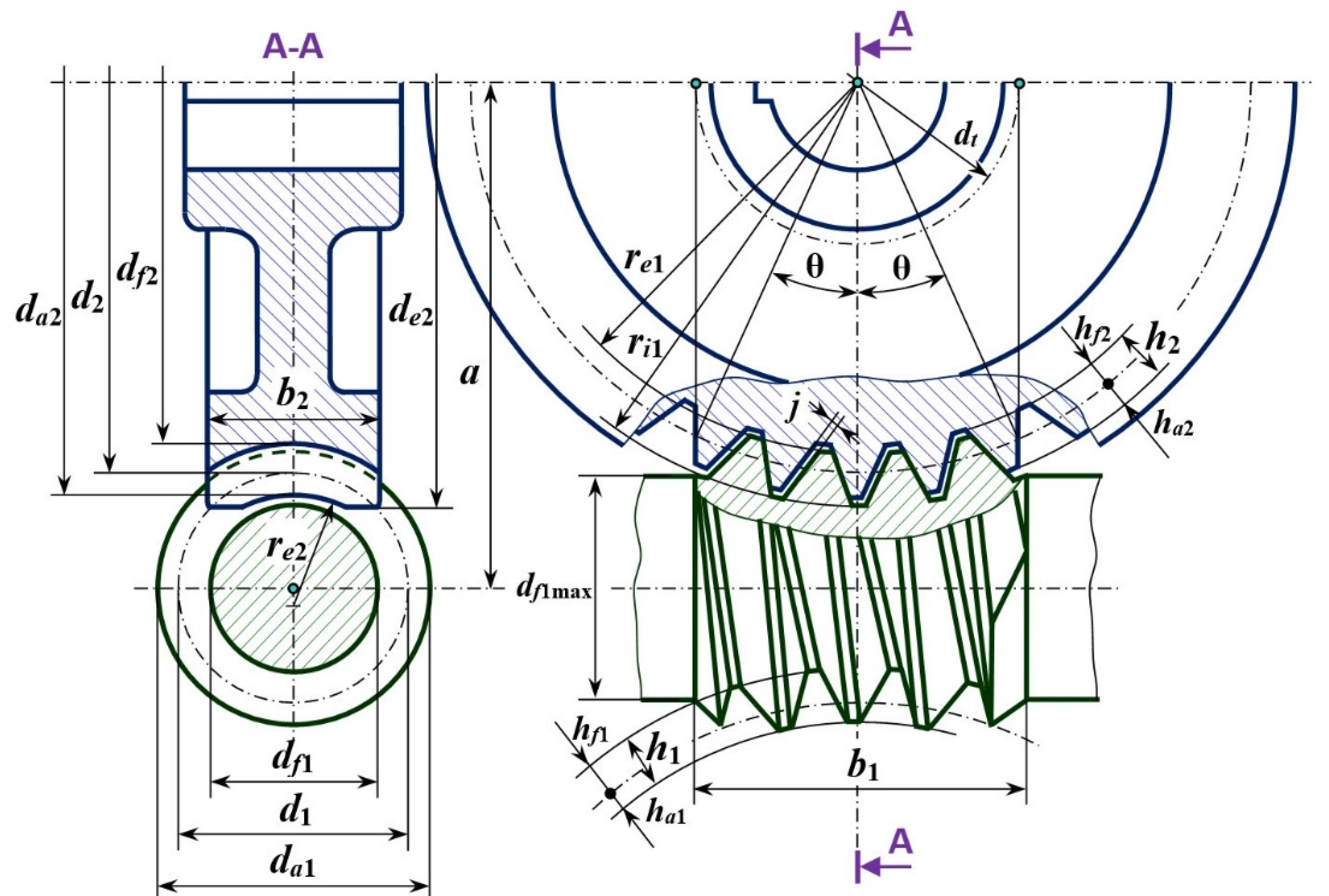
Figure 1. Globoid worm gear.
Applsci 14 10833 g001
Figure 2. Worm gear with a single row of bearings per roller.
Applsci 14 10833 g002
Figure 3. The geometry of the worm gear with bearings.
Applsci 14 10833 g003
Figure 4. The profile of the worm wheel.
Applsci 14 10833 g004
Figure 5. The worm–bearing contact: (a) 2D worm–bearing contact, (b) 3D worm–bearing contact.
Applsci 14 10833 g005
Figure 6. The velocity plane.
Applsci 14 10833 g006
Figure 7. The trajectory of point M. (a)—related to the worm; (b)—related to the worm wheel.
Applsci 14 10833 g007
Figure 8. The trajectories of A, B, C, and D points. (a)—A and B points; (b)—D and E points.
Applsci 14 10833 g008
Figure 9. The worm flank surface generated by sweeping the AB segment along the globoid-guided curve. (a)—isometric position; (b)—frontal position.
Applsci 14 10833 g009
Figure 10. The worm flank surface generated by sweeping the DE segment along the globoid-guided curve. (a)—isometric position; (b)—frontal position.
Applsci 14 10833 g010
Figure 11. An overlap image of the surfaces of the globoid worm generated by sweeping segments AB and DE through the globoid-guided curves.
Applsci 14 10833 g011
Figure 12. Generation of helices of the spiral.
Applsci 14 10833 g012
Figure 13. Three-dimensional model of the worm.
Applsci 14 10833 g013
Figure 14. Three-dimensional model of the gear.
Applsci 14 10833 g014
Figure 15. Three-dimensional prototype worm and bearings obtained through additive manufacturing.
Applsci 14 10833 g015
Figure 16. Prototype of the unconventional worm gear with bearings.
Applsci 14 10833 g016
Disclaimer/Publisher’s Note: The statements, opinions and data contained in all publications are solely those of the individual author(s) and contributor(s) and not of MDPI and/or the editor(s). MDPI and/or the editor(s) disclaim responsibility for any injury to people or property resulting from any ideas, methods, instructions or products referred to in the content.