Abstract
This paper presents the design and characterization of a coplanar waveguide (CPW) fed, low-profile, and flexible arrow-shaped filtenna for ISM band applications at 2.45 GHz. The antenna design involves an innovative approach incorporating etching slots to achieve miniaturization by 34%, contrasting with a traditional quadrilateral-shaped antenna. After the attainment of desired miniaturization, the unwanted harmonics are also mitigated by deploying simple filtering methodology. A perpendicular rectangular stub is strategically introduced to the feedline, effectively minimizing harmonics across a broad frequency range of 3.3–11.0 GHz. Through simulations and measurements, the results indicate that the antenna’s operational band spans from 2.276 to 2.75 GHz, encompassing the entire ISM band (2.4–2.5 GHz). Notably, the antenna demonstrates promising radiation characteristics, including omnidirectional gain of approximately 2.2 dBi and a radiation efficiency exceeding 95%. With a compact overall size of 0.24λ × 0.20λ × 0.0005λ (where λ is the free-space wavelength at 2.45 GHz), coupled with wide harmonic rejection property, the proposed arrow-shaped flitenna emerges as a compelling candidate for ISM band applications.
1. Introduction
Flexible electronics technologies have emerged as a leading trend in our modern world, recognized as a distinct category of electronics capable of conforming to various surface shapes. These technologies possess unique properties that allow them to bend, twist, and stretch, making them particularly versatile [1]. The proliferation of wearable devices in the electronics market is accelerating, driven by their application across multiple fields, including healthcare, energy harvesting, military applications, and the leisure industry [2,3,4]. This surge in interest stems from their unmatched characteristics, which facilitate the seamless integration of flexible electronics into daily activities, ultimately enhancing the quality of human life [5,6].
As wearable electronics technology continues to advance, ensuring reliable wireless connectivity necessitates the use of flexible antennas. The performance and effectiveness of such devices heavily depend on the characteristics of the integrated antenna [7]. A flexible antenna must be mechanically robust, capable of withstanding high levels of bending, folding, and flexing without degradation. However, these antennas face several challenges, such as resonant frequency variation, which occurs due to changes in effective capacitance when the antenna is bent or rolled [8]. Additionally, as the degree of bending increases, the radiation pattern can become distorted, directly impacting the antenna’s gain. Therefore, the design of flexible antennas must address these challenges to ensure consistent functionality in various operating conditions. Furthermore, the antenna should be lightweight and have a low profile to minimize any negative effects [9,10,11].
As discussed earlier, antenna designers must address frequency shifts and degradation in radiation characteristics during bending scenarios. To achieve this, highly effective antennas are required. Various types of antennas have been employed for flexible devices, such as microstrip antennas [12], slot antennas [13], planar inverted-F antennas (PIFA) [14], and fractal antennas [15]. Each antenna offers unique advantages and drawbacks based on the desired performance [16]. For example, fractal antennas are often preferred when high performance and miniaturization—up to 75%—are required, along with good radiation characteristics. This preference is due to the enhancement achieved through the modification of the antenna’s radiating element geometry rather than the addition of components. This approach reduces complexity, potential failure points, and the overall cost of the antenna [17].
In recent years, several flexible fractal antennas have been reported in the literature. For example, a Sierpinski carpet fractal antenna is presented in [18], which exhibits stable radiation characteristics under bending conditions. However, the substrate used is rather bulky, with dimensions of 70 mm × 31 mm × 0.075 mm. In [19], a portable and flexible pre-fractal antenna is discussed, offering better control of resonant frequency and improved radiation characteristics. Despite these benefits, the complexity of this antenna design is notably high. Additionally, several interesting works on fractal flexible antennas for energy harvesting applications can be found in [20,21,22]. While these antennas demonstrate good performance in terms of impedance and gain, they share a common limitation—narrow bandwidth.
Furthermore, electromagnetic interference is another challenge to consider when designing highly efficient antennas for flexible devices. This is because integrated antennas generate detrimental electromagnetic radiation that can cause interference with other systems, thus affecting the performance of the overall system. Therefore, interfering signals must be rejected to avoid transmission degradation [23]. Various techniques are used to suppress harmonic resonances. The most well-known method is to introduce a filter in an RF circuit [24,25,26]. Contrary to this, a filter integrated with the antenna structure is also a possible solution to this uprising challenge. The co-design of antennas and filters, also known as “filtennas”, is gaining traction in wireless communication system design due to its potential for enhancing performance while minimizing size [27,28]. Integrating filtering functionality with antennas or replacing the last resonator of a filter with an antenna allows for compact and efficient designs that meet the demands of modern wireless systems [29,30]. These strategies help manage the trade-offs between size reduction and performance. One common approach involves etching slots, slits, or adding parasitic elements to the antenna [31,32,33,34]. While these modifications can lead to size reduction, they may introduce drawbacks like reduced gain, altered polarization, and degraded radiation patterns.
On the other hand, filters can provide high selectivity, improve out-of-band rejection (essential for minimizing interference), and help maintain antenna performance even in compact designs. Patch and monopole antennas are commonly employed for filtenna designs because of their simplicity and adaptability in integrating filtering functions [33,35,36,37,38,39,40]. In the same way, the work in [41] investigated a uniplanar differential-fed transparent circular filtenna with defected ground structure. In [42], another design approach involving an inverted microstrip gap waveguide technology is employed to design filtenna. Although this design integrates the co-planar EBG filters with gap waveguide technology to avoid unwanted radiation and to reduce interfering signals, this multilayered approach involves more design and fabrication complexity. Although the antennas presented in these works successfully reject spurious radiation, the addition of filters increases the complexity and size of the design, making it less amenable to miniaturization and integration. Other approaches to harmonic suppression have been discussed in the literature, including the introduction of photonic band gap structures [43], tuning stubs [44], etc. However, the disadvantage of the structure being too bulky still persists. Hence, the focus on combining antennas and filters is part of the broader effort to develop smaller, more efficient wireless communication components. These innovations are crucial for modern communication systems that demand high performance, compactness, and functionality in constrained environments.
To summarize, the flexible electronics market requires the use of efficient non-rigid antennas characterized by wide bandwidth, good radiation characteristics, and good matching. On the other hand, the option of harmonic suppression must be incorporated in order to reduce interference while keeping a miniaturized profile in order to facilitate the integration of the antennas into miniaturized components. In this scenario, this work presents a flexible fractal antenna, characterized by a compact profile, and provided with the characteristic of harmonic rejection. The antenna is supposed to operate at a frequency ranging from 2.276 to 2.72 GHz, effectively covering the ISM band.
The key contribution of the proposed work is as follows:
- The proposed antenna consists of simple configurations that significantly reduce the fabrication errors for massive production.
- Compact size and high gain as compared with related products make it a strong candidate for targeted applications.
- Stable performance is achieved in both rigid and conformal scenarios.
- Along with confirmability, the proposed antenna offers filtering properties that are validated using measured results.
2. Filtering Antenna Design and Analysis
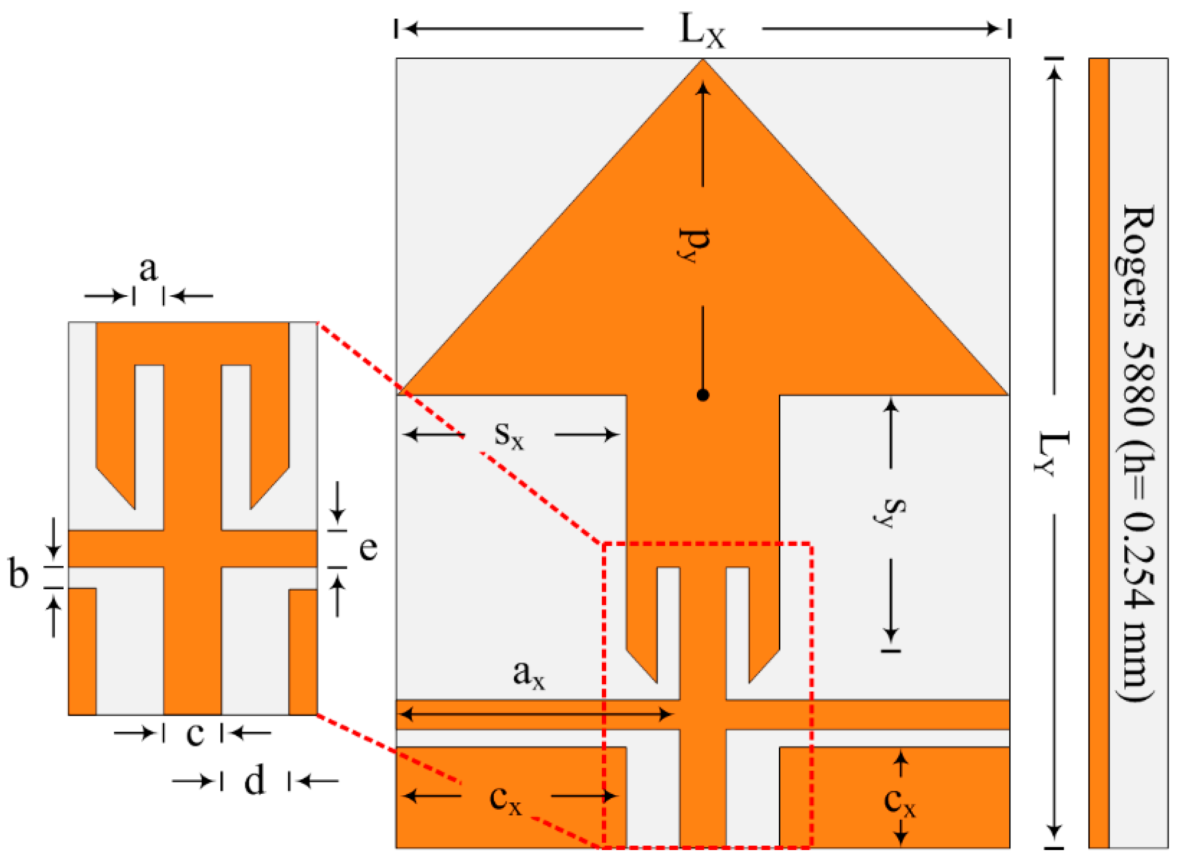
The proposed arrow-shaped flexible filtenna is designed and simulated by using the EM software tool CST Studio Suite® version 2023, and its final layout is depicted in Figure 1. It can be seen in the figure that proposed filtenna consist of a coplanar waveguide (CPW) feed line and an arrow-shaped patch. Two slots are etched from the tail of the arrow-shaped patch, and a rectangular stub is loaded to further optimize the performance of filtenna. The overall size of the proposed filtenna is LX × LY × h = 23 mm × 30 mm × 0.254 mm. The structure of the antenna is designed over flexible substrate material Rogers RT/duroid 5880 with 0.254 mm thickness, a relative permittivity of 2.2, and a loss tangent of 0.0009 [45]. The optimized parameters and final layout of the proposed design are provided in Figure 1.

Figure 1.
Proposed filtering antenna having optimized dimensions of LX = 23, LY = 30, py = 11.5, sx = 7.5, sy = 12.5, ax = 10.6, cx = 3.4, cy = 9.5, a = 1, b = 1.1, c = 1.8, d = 1.1, and e = 2. (unit: mm).
2.1. Antenna Design
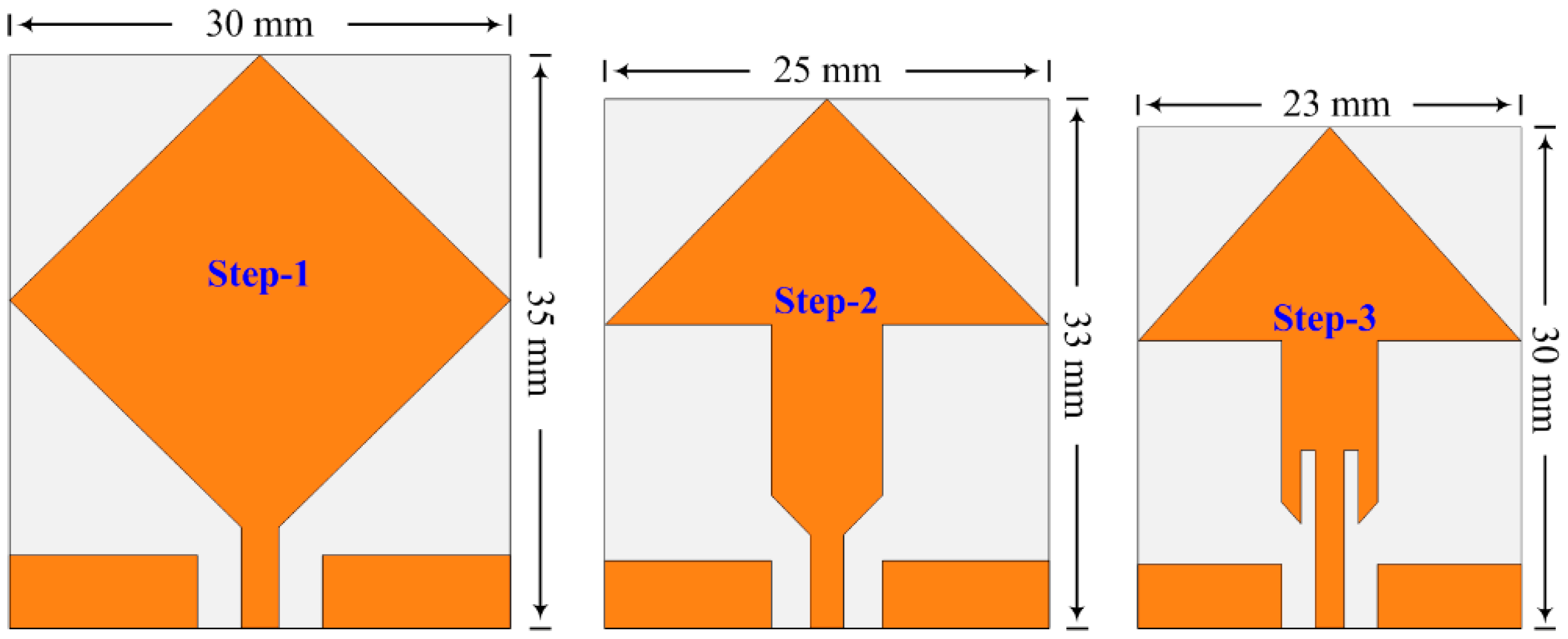
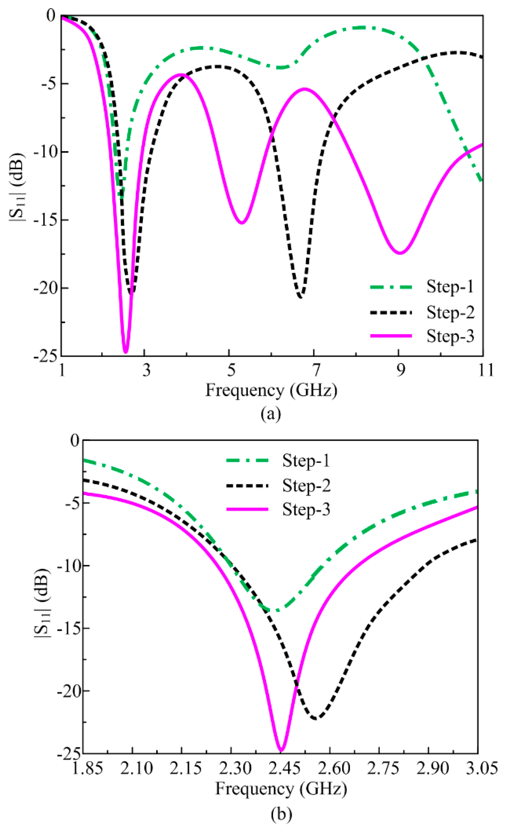
Figure 2 illustrates the steps involved in the design of the proposed arrow-shaped flexible antenna. The obtained S-parameter results for each design step are shown in Figure 3a, whereas Figure 3b shows the expanded view to get a closer look at the effects of various design optimizations on the ISM band. The S-parameter, also referred to as the reflection coefficient, is a critical parameter as it shows that loss in power, which consequently explains how much power is successfully transmitted [46]. For modern-day devices, the rule of S11 < −10 dB is utilized, and bandwidth is the frequency having the value that satisfied the rule.

Figure 2.
Antenna design methodology steps.
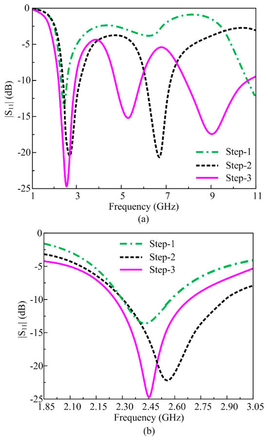
Figure 3.
(a) Return loss of various antennas involved in design methodology; (b) close-up shot.
Step 1: Initially, a rhombus-shaped antenna with an overall geometrical size of 30 mm × 30 mm is designed by rotating the square-shaped patch at 45°. The antenna is fed by a coplanar waveguide feedline. The antenna dimensions at this stage are obtained by using standard mathematical formulas [47]. The antenna designed in this step offers dual resonances at 2.45 GHz and 11 GHz, as depicted in Figure 3a. The obtained results exhibit that the impedance matching is not good at the targeted frequency band of 2.45 GHz.
Step 2: In the second step, the design is modified into an arrow-shaped antenna by truncating the lower half of the patch. Also, the antenna design is miniaturized at this step to obtain the overall dimensions of 25 mm × 33 mm. This modification results in the improvement of bandwidth and impedance matching. However, minor shifting is observed from 2.45 GHz to 2.6 GHz for the lower band, whereas the upper band is also shifted from 11 GHz to 6.8 GHz, as shown in Figure 3.
Step 3: In this final step, the proposed antenna is further miniaturized to 23 mm × 30 mm. Two rectangular slots are etched from the lower end of the arrow-shaped patch antenna. Furthermore, two additional triangular-shaped slots are etched from the lower side of the antenna. As a result, a third resonance is obtained at 9 GHz, as illustrated in Figure 3a, in addition to further improvement in impedance matching of already obtained bands.
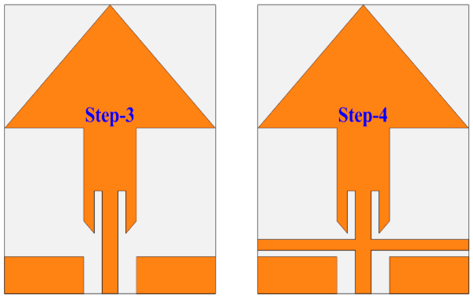
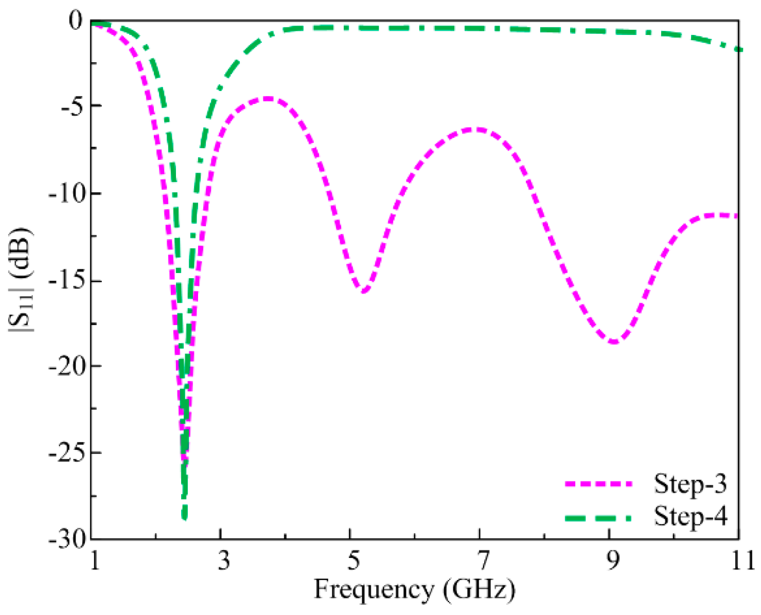
2.2. Filtenna Design
The antenna design obtained in the previous section is further optimized to obtain the filtering characteristics. Following the antenna obtained previously with miniaturized dimensions of 23 mm × 30 mm, an additional rectangular-shaped stub is loaded between feedline and antenna. This additional stub filters out the upper band resonances at 5.2 GHz and 9 GHz and results in an antenna operating over the 2.45 GHz band. The resultant antenna offers harmonic suppression from 3 GHz to 11 GHz in order to reduce interference and an operational band at 2.45 GHz. The design steps are depicted in Figure 4, and the corresponding S-parameter results are demonstrated in Figure 5.

Figure 4.
Filtering antenna design methodology.
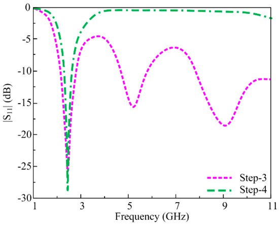
Figure 5.
Effects on return loss with and without filtering stub.
2.3. Parametric Analysis
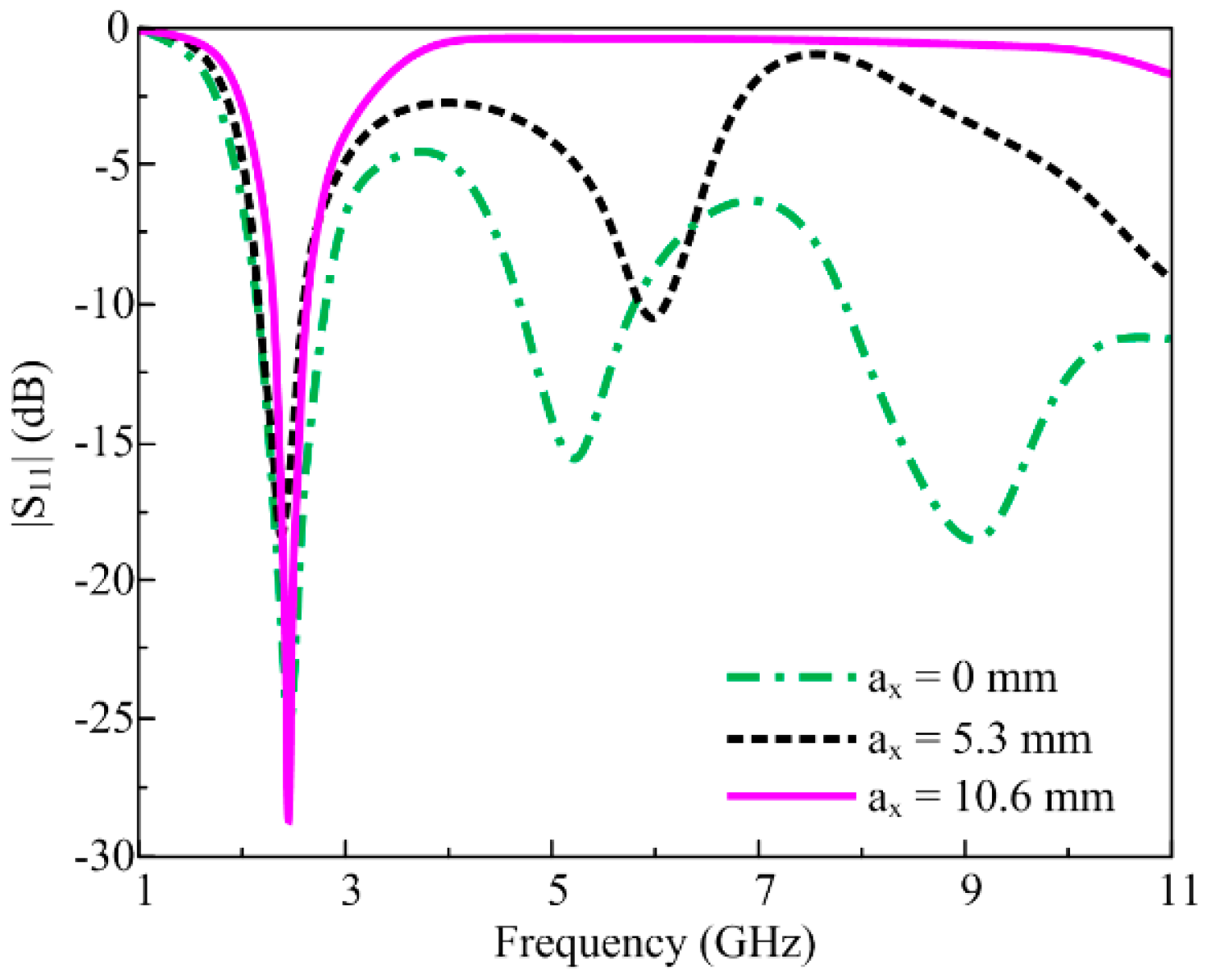
Figure 6 shows the parametric analysis for length of the stub (ax) used to obtain the desired operational band at 2.45 GHz and suppress the other harmonic bands. It can be seen from the figure that the antenna obtained in Section 2.1 is transformed to filtenna by loading a rectangular-shaped stub having a length of 10.6 mm. At the optimal value of ax = 10.6 mm, the antenna offers wide harmonic suppression of upper bands, whereas the ISM band ranging from 2.3 to 2.75 GHz remains operational. If the value of ax is fixed at half of the optimal value (ax = 5.3 mm), the upper band at 11 GHz is only suppressed, as evident in Figure 6. If the length of ax is further decreased to 0 mm, the antenna is no longer filtenna. It starts operating in tri-mode of 2.45 GHz, 5.2 GHz, and 9.1 GHz, as shown in Figure 6.

Figure 6.
Effects on return loss with and without filtering stub.
Table 1 summarizes the antenna performance at various design stages considering the different parameters. It can be observed that antenna at step 1, with overall dimensions of 30 mm × 35 mm, offers 2.35–2.47 ISM band with harmonic at 10.7–11.5 GHz. This initial stage did not offer any filtering band. The antenna design after step 2, with a geometrical size of 25 mm × 33 mm, obtained an ISM band ranging from 2.4 to 2.8 GHz with 6.2–7.4 GHz harmonic. The antenna designed at the third stage, having a size of 23 mm × 25 mm, offers a 2.3–2.75 GHz operational band and two harmonics ranging from 5.0 to 5.5 GHz and 8.2–10 GHz. The final proposed antenna, with an overall size of 23 mm × 25 mm, offers an ISM band ranging from 2.276 to 2.75 GHz, with no harmonics, but with a filtering band ranging from 3 to 11 GHz.

Table 1.
Performance comparison among design methodology steps.
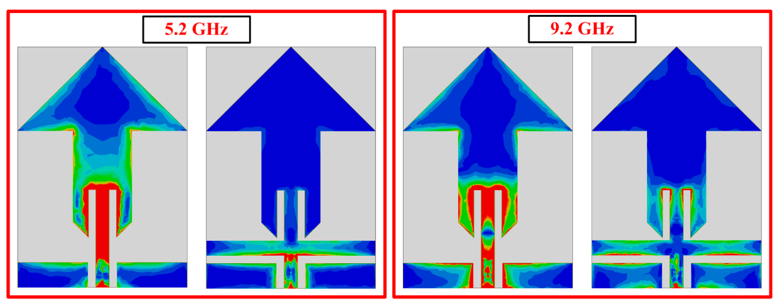
To further elaborate the operational behavior of proposed filtenna, the surface current distribution is provided at two filtered resonances of 5.2 GHz and 9 GHz, as illustrated in Figure 7. It can be seen that at 5.2 GHz, where there is no rectangular stub, the maximum current is on feedline and slots at the tail of an arrow-shaped patch. However, after the inclusion of the stub, the current at the upper part of the antenna is minimum, with the maximum amount of current at the edges of the rectangular-shaped stub, which is used to filter the resonance. Similarly for 9 GHz, the maximum amount of current is observed at the lower end of the antenna and feedline without a stub. On the other hand, when the rectangular stub is loaded, the maximum amount of current is noted at the edges of the loaded stub and feedline.
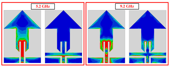
Figure 7.
Current distribution of the antenna at various frequencies.
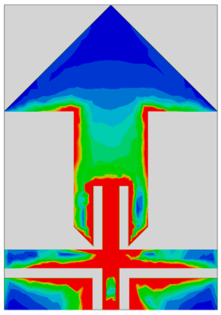
Also, it is noticed that at 2.45 GHz the maximum number of current flows along the feedline and edges of the rectangular stubs as well as the arrow-shaped antenna, as depicted in Figure 8. Thus, it is verified that the rectangular stub leads towards the harmonic suppression of upper frequency bands, resulting in resonance at the desired ISM band.
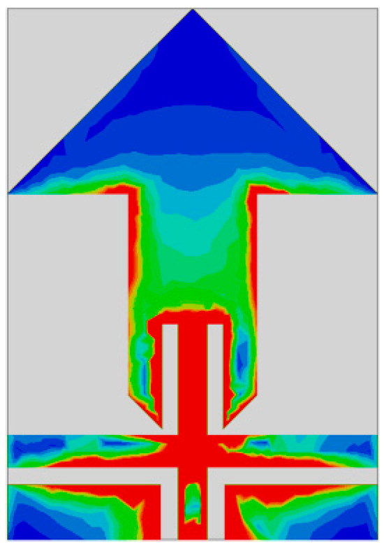
Figure 8.
Current distribution of the antenna at a central frequency of 2.45 GHz.
3. Experimental Results
The performance of the proposed antenna is validated by carrying out experimental investigations on the fabricated prototype, as depicted in Figure 9. A detailed analysis of the simulated and measured results of the proposed filtenna is provided in the succeeding sections. In addition, conformability analysis is also provided for the proposed filtenna.
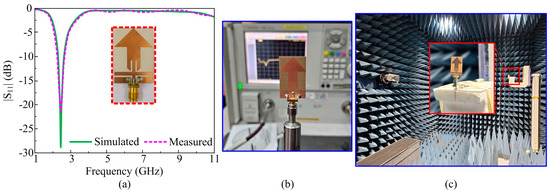
Figure 9.
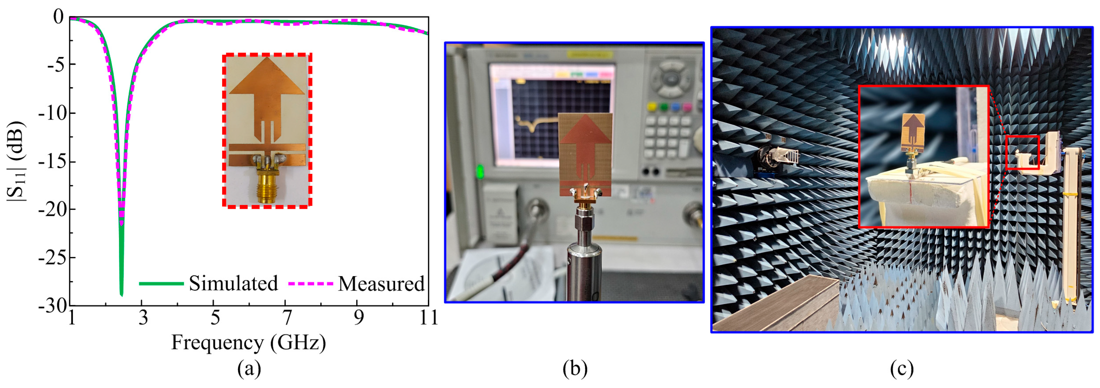
(a) Simulated and measured S11 comparison of filtering antenna; (b) S-parameter measurement setup; and (c) far-field measurement setup.
3.1. |S11|
Figure 9a exhibits the comparison of simulated and measured |S11| results of proposed filtenna. It is noticed that the proposed arrow-shaped filtenna obtained am ISM band at 2.45 GHz ranging from 2.276 to 2.75 GHz, demonstrating the strong correlation between simulated and measured results. The results obtained by the proposed design ascertain their suitability as a potential candidate for future portable electronic devices operating at the ISM band. Figure 9b contains the antenna prototype under test for S-parameter measurements using a PNA series network analyzer having model number E8362B by Agilent Technologies (Santa Clara, CA, USA). Moreover, Figure 9c contains the antenna for far-field measurements inside the anechoic chamber.
3.2. Radiation Pattern and Surface Current Distribution
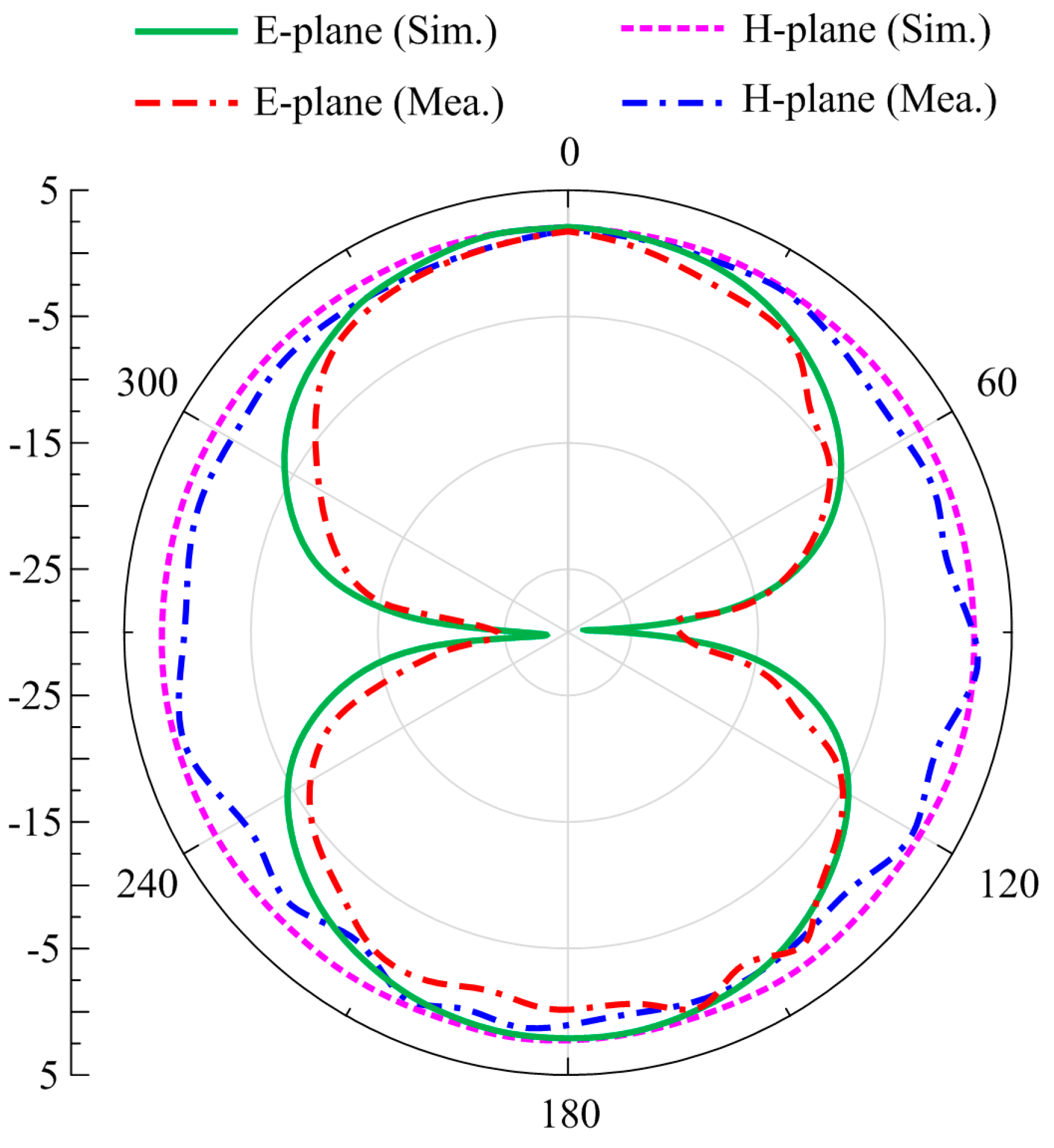
The far-field behavior of the proposed filtenna is investigated at 2.45 GHz, as shown in Figure 10. It is observed that the filtering antenna exhibits bi-directional radiational patterns in the E-plane while an omni-directional pattern in the H-plane is observed for the selected frequency, where strong agreement is noticed for the simulated and measured results. However, slight variation between simulated and measured results is mainly attributed to the fabrication and installation tolerance and test errors.
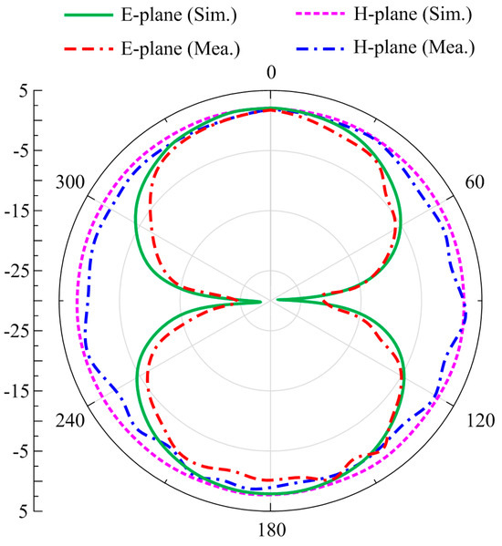
Figure 10.
Radiation pattern of the proposed filtenna at 2.45 GHz.
3.3. Gain and Efficiency
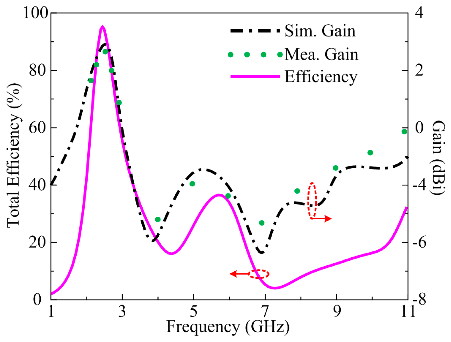
Figure 11 represents the gain and radiation efficiency of the proposed flexible filtenna. It can be seen from the displayed figure that the antenna offers gain >2.6 dBi throughout the operational bandwidth of 2.2–2.8 GHz with a peak value of 2.9 dBi at a resonance frequency of 2.45 GHz. It is also observed that at filtering spectrum 3–11 GHz, the antenna gain is below −3 dBi. The measured value provides strong support in favor of simulated results. Furthermore, the radiation efficiency plot in Figure 10 demonstrates a value >90% over the entire operational spectrum, whereas for filtered bands the value of efficiency is less than 40%. The farfield performance of the proposed flexible filtenna endorses it as a suitable contender for imminent electronic devices operating over the ISM band.

Figure 11.
Efficiency of the proposed filtenna along with gain results.
3.4. Conformal Analysis
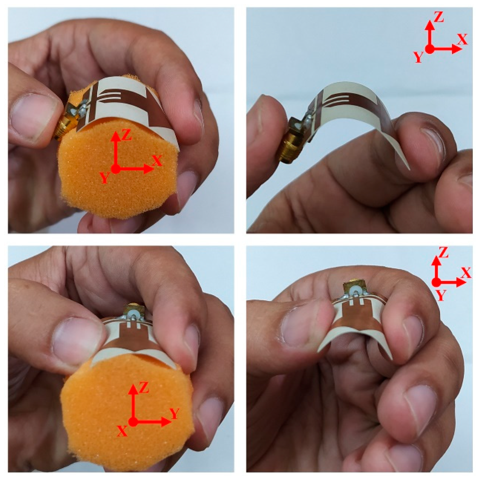
As stated earlier, the proposed filtenna is designed on the flexible substrate material with a thickness of 0.254 mm; therefore, in this section, the conformal analysis of the proposed filtenna will be discussed. As illustrated in Figure 12 and Figure 13, the bending analysis is performed for both the x- and y-axis in the simulation environment as well as for the hardware prototype. The conformal analysis is performed by bending the filtenna over a cylinder having a radius of 10 mm, 15 mm, and 20 mm in both the x- and y-axis.
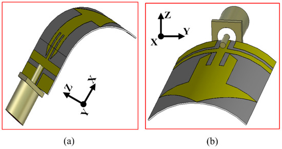
Figure 12.
Simulated setup of bending along (a) x-axis (b) y-axis.

Figure 13.
Fabricated prototype bending analysis of the proposed filtenna in the x- and y-axis.
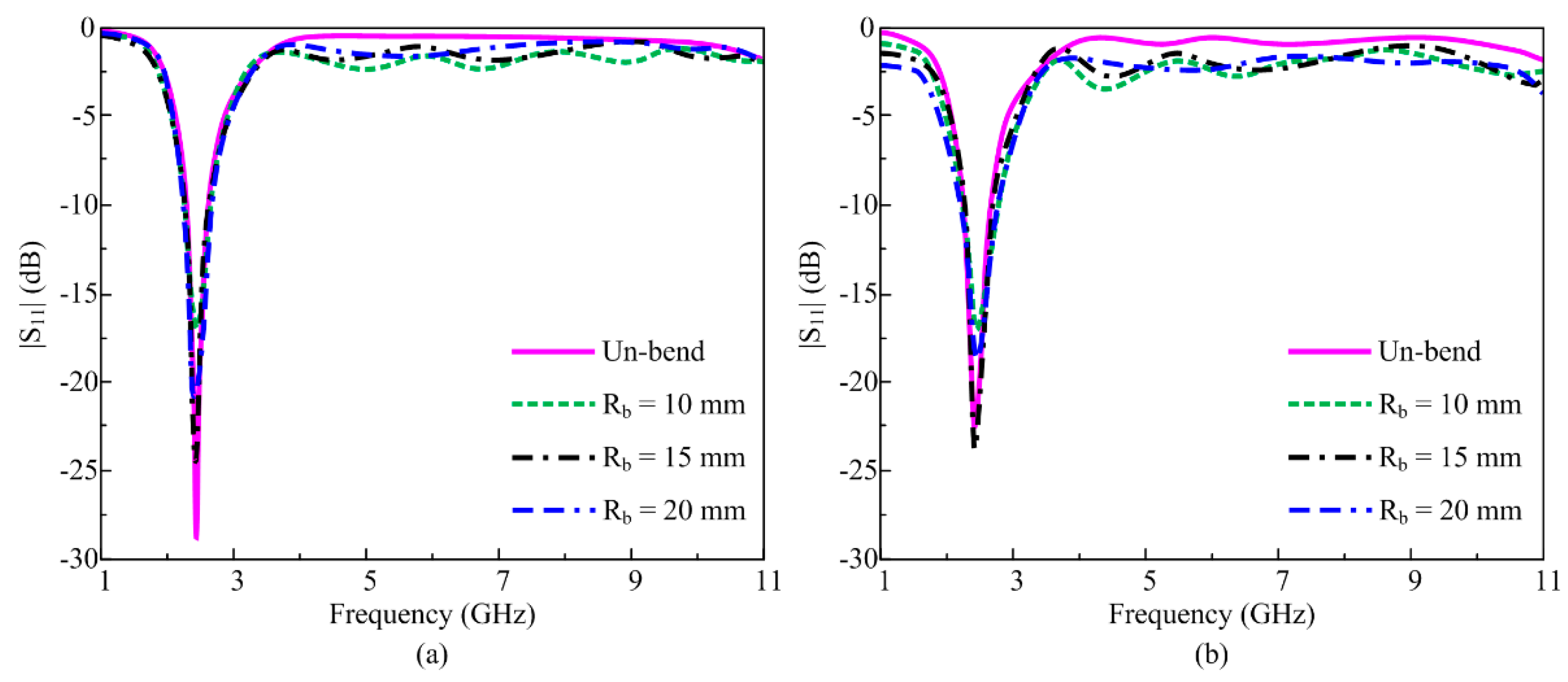
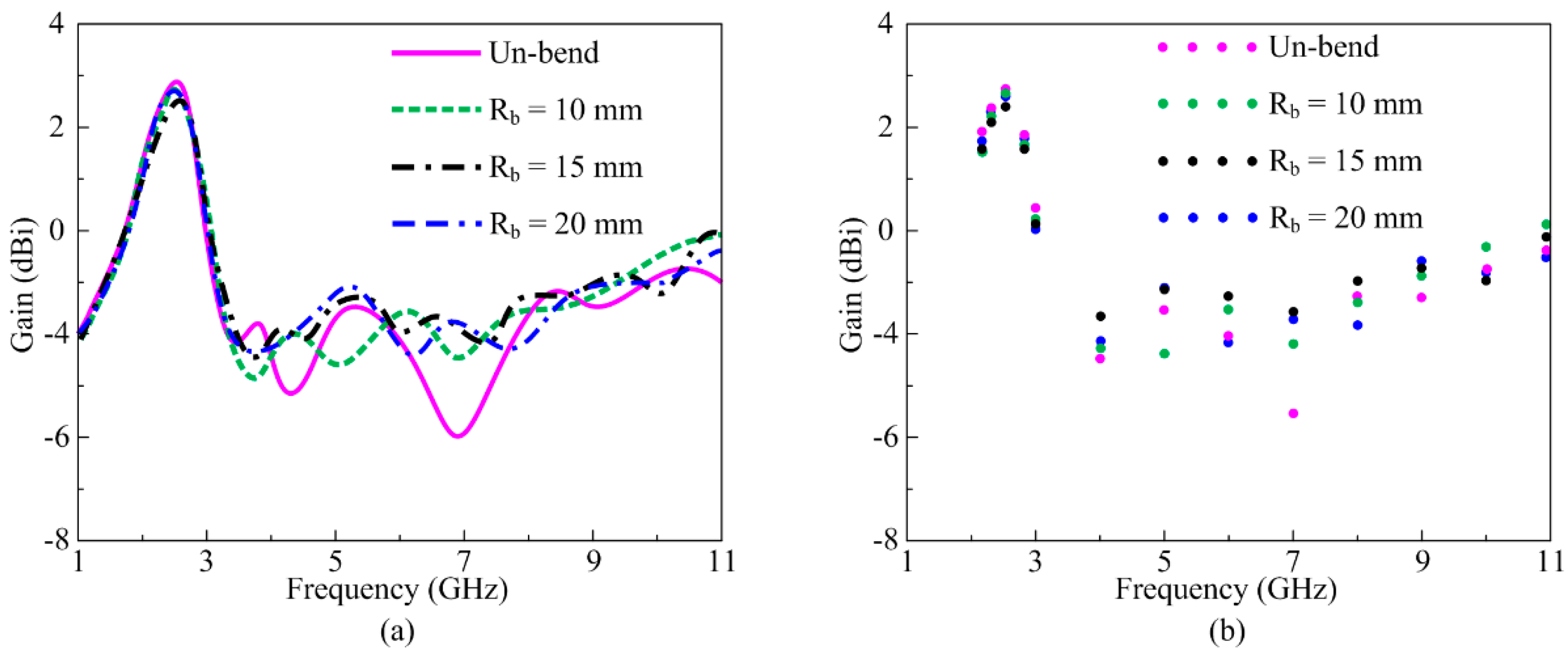
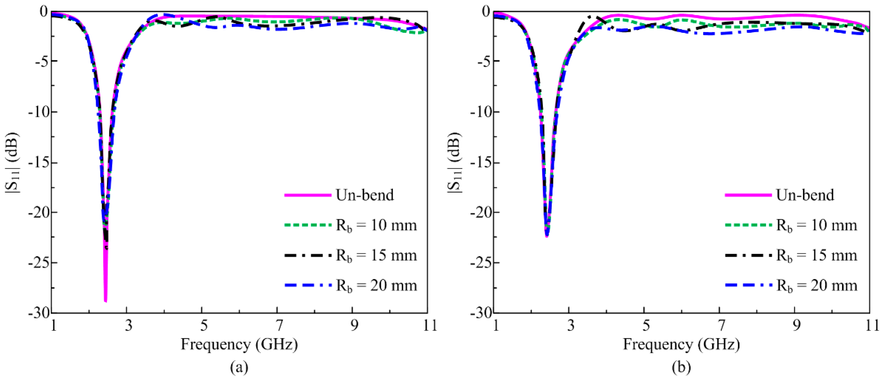
Figure 14a,b shows the simulated and measured S-parameter plots of the proposed flexible filtenna in unbent and bent conditions with radii of 10 mm, 15 mm, and 20 mm. It is noted that when filtenna is bent along the x-axis at various radii, the rectangular stub and upper part of the patch are folded, which results in slight distortion in antenna performance as compared to the unbent condition, also evident from the S11 plots in Figure 14. However, the overall filtering performance of filtenna remains stable with desired resonance in the ISM band and highly suppressed for the upper frequency bands. Similarly, Figure 15a,b exhibit the simulated and measured gain of the antenna for unbent as well as bent configurations along the x-axis. It is noticed that the antenna, when bent at various radii, offers gain > 2.5 dB through an operational bandwidth of 2.2–2.8 GHz, whereas for the filtering band ranging from 3 to 11 GHz, the gain value of <−4 dB is obtained. Hence, it is verified that the filtenna performance remains stable regardless of being folded. The measured value of gain also provides good agreement with simulated results.
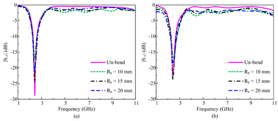
Figure 14.
S-parameter of the proposed filtenna bend over the x-axis. (a) Simulated and (b) measured.
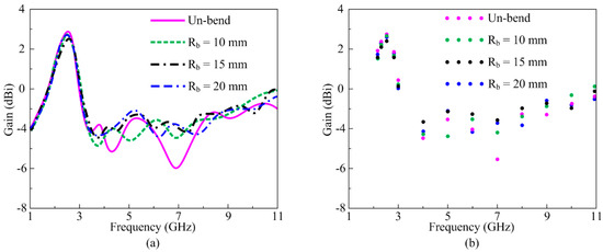
Figure 15.
Gain and efficiency of the proposed filtenna bend over the x-axis. (a) Simulated and (b) measured.
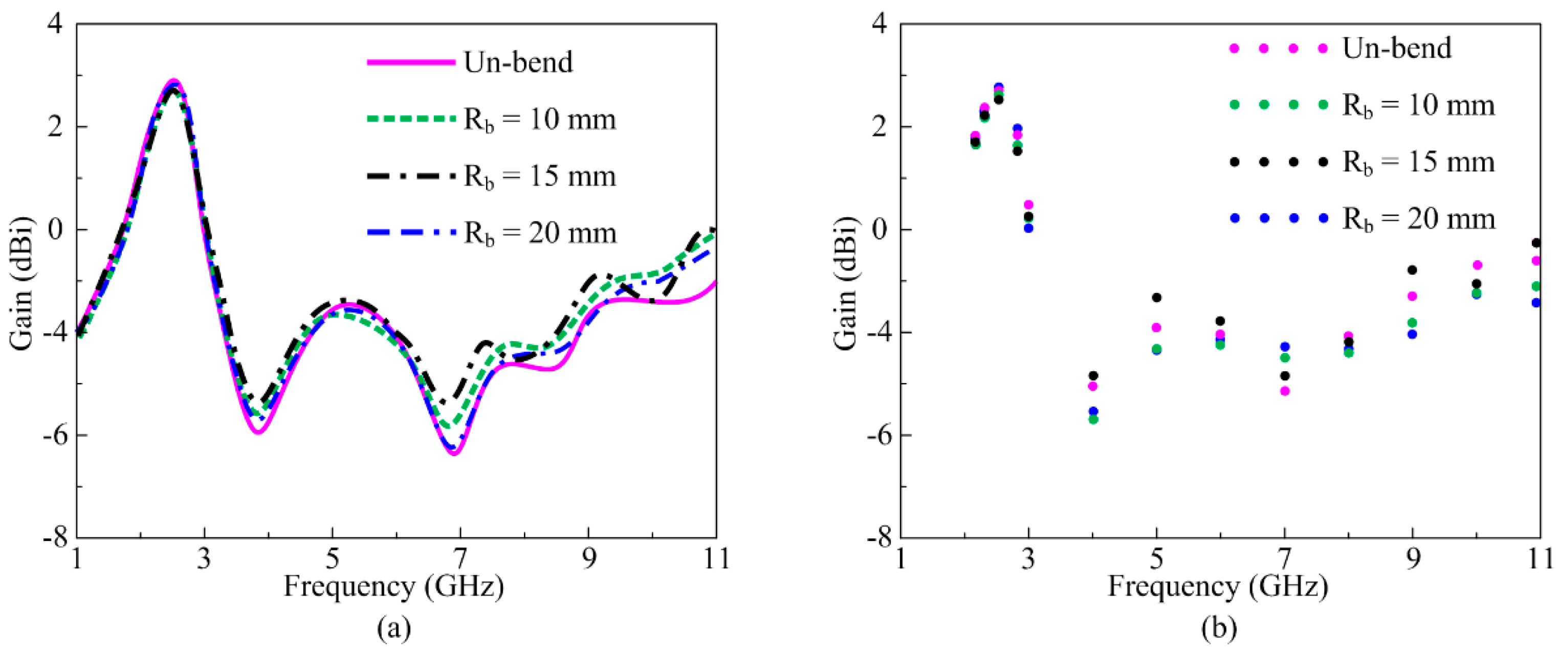
In the same way, the bending analysis of proposed filtenna at radii of 10, 12, and 15 mm along the y-axis is demonstrated in Figure 16a,b. As the rectangular stub plays a major role in filtering the upper frequency bands, a minor distortion is observed for the S-parameter, resulting in a bent state due to the bending of the rectangular stub and the side edges of the arrow-shaped patch. However, this distortion is insignificant, and the overall performance of the filtenna remains unaffected. In addition to S-parameter results, simulated and measured gain for the proposed filtenna in bent condition along the y-axis at 10 and 12 mm radii is exhibited in Figure 17a,b. It is found that proposed filtenna offers gain >2.5 dBi throughout the operational band of 2.2–2.8 GHz, whereas for the filtered band ranging from 3 to 11 GHz, the gain remains negative. Simulated and measured results are in strong agreement, ascertaining the pertinence of proposed filtenna for current and impending flexible electronic devices.
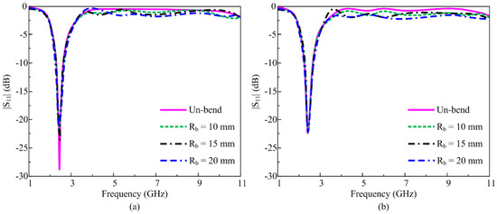
Figure 16.
S-parameter of the proposed filtenna bend over the y-axis. (a) Simulated and (b) measured.
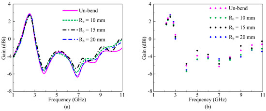
Figure 17.
Gain and efficiency of the proposed filtenna bend over the y-axis. (a) Simulated and (b) measured.
4. Performance Comparison
Table 2 summarizes the comparative analysis of proposed flexible filtenna with other relevant works reported recently in the literature. The comparison is provided against various performance metrics, including size, impedance bandwidth, gain, flexibility, and filtering characteristics. It is clear from the table that the proposed antenna offers compactness, wide bandwidth, and significant gain for the resonant band, while filtering capability is also attained for undesired bands. In addition, confirmability is also achieved for the proposed filtenna. Overall, this developed filtenna has significant advantages over other works for application in radio frequency front-end platforms with the inevitable future requirements of compactness.
Table 2.
Comparison of ISM band antennas with proposed filtering antenna.
5. Conclusions
This article focuses on the design and analysis of a compact-size antenna integrated with a filter to suppress the higher-order harmonics. The proposed antenna works for the 2.45 GHz industry–science–medical (ISM) band, one of the globally used band spectrums. Initially, miniaturization in the antenna size is achieved using 3 consecutive steps that result in 34% miniaturized size as compared to conventional antennas. Afterwards, a filtering stub is utilized to suppress the higher-order undesired harmonics that may result in unwanted interference. Finally, the antenna is optimized to achieve the resonance at the desired band of 2.45 GHz, as the miniaturization along with filtering structure results in shifting of the central frequency. The antenna prototype is fabricated, and experimental results for both conformal and rigid cases are obtained and later compared with the simulated results. The antenna offers a broadband ranging from 2.276 to 2.75 GHz that covers the globally allocated ISM band of 2.4–2.5 GHz. Moreover, the antenna gain value of >2.5 dBi having an omni-directional radiation pattern along with a radiation efficiency of >95% is achieved for the proposed filtenna. The antenna over-performs the literary works due to high performance parameters along with an overall compact size of 0.24λ × 0.20λ × 0.0005λ and stable filtering properties in both rigid as well as conformal cases, making it a strong candidate for modern-day applications.
Author Contributions
Conceptualization, W.A.A.; methodology, software, M.H. and W.A.A.; validation, formal analysis, investigation, S.I.N. and A.A.; resources, data curation, W.A.A. and S.I.N.; writing—original draft preparation, M.H. and A.A.; writing—review and editing, W.A.A. and S.I.N.; funding acquisition, supervision, W.A.A.; project administration, S.I.N. All authors have read and agreed to the published version of the manuscript.
Funding
This research received no external funding.
Institutional Review Board Statement
Not applicable.
Informed Consent Statement
Not applicable.
Data Availability Statement
The original contributions presented in the study are included in the article, further inquiries can be directed to the corresponding author.
Conflicts of Interest
The authors declare no conflicts of interest.
References
- Khaleel, H. Innovation in Wearable and Flexible Antennas; Wit Press: Boston, MA, USA, 2014. [Google Scholar]
- Al-Haddad, M.A.S.M.; Jamel, N.; Nordin, A.N. Flexible antenna: A review of design, materials, fabrication, and applications. J. Phys. Conf. Ser. 2021, 1878, 012005. [Google Scholar] [CrossRef]
- Hu, F.; Qiu, L.; Zhou, H. Medical Device Product Innovation Choices in Asia: An Empirical Analysis Based on Product Space. Front. Public Health 2022, 10, 871575. [Google Scholar] [CrossRef]
- Zhang, L.; Kou, H.; Pang, Y.; Yang, L.; Zhang, X.; Shang, Z.; Zhang, L. Design of Temperature-Pressure Sensor Based on Slot-Antenna CSRR Integrated for Applications in High-Temperature Environments. IEEE Sens. J. 2024, 24, 27218–27224. [Google Scholar] [CrossRef]
- El Gharbi, M.; Fernández-García, R.; Ahyoud, S.; Gil, I. A review of flexible wearable antenna sensors: Design, fabrication methods, and applications. Materials 2020, 13, 3781. [Google Scholar] [CrossRef] [PubMed]
- Ghaffar, A.; Awan, W.A.; Hussain, N.; Ahmad, S.; Li, X.J. A compact dual-band flexible antenna for applications at 900 and 2450 MHz. Prog. Electromagn. Res. Lett. 2021, 99, 83–91. [Google Scholar] [CrossRef]
- Ali, U.; Ullah, S.; Basir, A.; Kamal, B.; Matekovits, L.; Yoo, H. Design and SAR analysis of AMC-based fabric antenna for body-centric communication. IEEE Access 2023, 11, 73894–73911. [Google Scholar] [CrossRef]
- Dey, A.B.; Arif, W. On-body low-profile compact AMC-integrated wideband antenna for body area network applications. IETE Tech. Rev. 2024, 41, 133–146. [Google Scholar] [CrossRef]
- Hussain, M.; Zahra, H.; Asadnia, M.; Abbas, S.M.; Zhu, Y. PDMS based dual band flexible antenna for ISM and WLAN portable applications. In Proceedings of the 2024 4th URSI Atlantic Radio Science Meeting (AT-RASC), Gran Canaria, Spain, 26 May–1 June 2024. [Google Scholar]
- Hussain, N.; Awan, W.A.; Naqvi, S.I.; Ghaffar, A.; Zaidi, A.; Naqvi, S.A.; Iftikhar, A.; Li, X.J. A compact flexible frequency reconfigurable antenna for heterogeneous applications. IEEE Access 2020, 8, 173298–173307. [Google Scholar] [CrossRef]
- Wang, Q.; Sihvola, A.; Qi, J. A Novel Procedure to Hybridize the Folded Transmitarray and Fabry–Perot Cavity with Low Antenna Profile and Flexible Design Frequency. IEEE Antennas Wirel. Propag. Lett. 2024, 23, 2501–2505. [Google Scholar] [CrossRef]
- Wang, C.; Zhang, L.; Wu, X. A wearable flexible microstrip antenna based on the floating-ground backplane. Int. J. RF Microw. Comput. Aided Eng. 2021, 31, e22481. [Google Scholar] [CrossRef]
- Das, S.; Mitra, D. A compact wideband flexible implantable slot antenna design with enhanced gain. IEEE Trans. Antennas Propag. 2018, 66, 4309–4314. [Google Scholar] [CrossRef]
- Marasco, I.; Niro, G.; Rizzi, F.; De Vittorio, M.; D’Orazio, A.; Grande, M. Design of a PEN-based flexible PIFA antenna operating in the sub-6GHz band for 5G applications. In Proceedings of the 22nd International Conference on Transparent Optical Networks (ICTON), Bari, Italy, 19–23 July 2020; pp. 1–4. [Google Scholar]
- Awan, W.A.; Hussain, N.; Le, T.T. Ultra-thin flexible fractal antenna for 2.45 GHz application with wideband harmonic rejection. AEU-Int. J. Electron. Commun. 2019, 110, 152851. [Google Scholar] [CrossRef]
- Zha, S.; Qu, Z.; Zhang, J.; Zheng, D.; Liu, P. A Gain-Reconfigurable Reflector Antenna with Surface-Mounted Field-Induced Artificial Magnetic Conductor for Adaptive HIRF Prevention. IEEE Trans. Antennas Propag. 2024, 72, 7252–7260. [Google Scholar] [CrossRef]
- Nichita, M.V.; Paun, M.A.; Paun, V.A.; Paun, V.P. On the 5G communications: Fractal-shaped antennas for PPDR applications. Complexity 2021, 2021, 9451730. [Google Scholar] [CrossRef]
- Radonić, V.; Palmer, K.; Stojanović, G.; Crnojević-Bengin, V. Flexible Sierpinski carpet fractal antenna on a Hilbert slot patterned ground. Int. J. Antennas Propag. 2012, 2012, 980916. [Google Scholar] [CrossRef]
- Silva Junior, P.F.; Santana, E.E.; Pinto, M.S.; Freire, R.; Oliveira, M.A.; Fontgalland, G.; Silva, P.H. Flexible wearable pre-fractal antennas for personal high-temperature monitoring. Wirel. Pers. Commun. 2020, 114, 1983–1998. [Google Scholar] [CrossRef]
- Shrestha, S.; Lee, S.R.; Choi, D.Y. A new fractal-based miniaturized dual band patch antenna for RF energy harvesting. Int. J. Antennas Propag. 2014, 2014, 805052. [Google Scholar] [CrossRef]
- Shi, Y.; Fan, Y.; Jing, J.; Yang, L.; Li, Y.; Wang, M. An efficient fractal rectenna for RF energy harvest at 2.45 GHz ISM band. Int. J. RF Microw. Comput. Aided Eng. 2018, 28, e21424. [Google Scholar] [CrossRef]
- Kumar, S.B.; Singhal, P.K. RF energy harvesting using Sierpinski’s gasket fractal antenna with EBG geometry. J. Inform. Optim. Sci. 2020, 41, 99–106. [Google Scholar] [CrossRef]
- Yang, Y.; Zhang, Z.; Zhou, Y.; Wang, C.; Zhu, H. Design of a Simultaneous Information and Power Transfer System Based on a Modulating Feature of Magnetron. IEEE Trans. Microw. Theory Tech. 2023, 71, 907–915. [Google Scholar] [CrossRef]
- Yuan, Y.; Qin, G.; Li, D.; Zhong, M.; Shen, Y.; Ouyang, Y. Real-Time Joint Filtering of Gravity and Gravity Gradient Data Based on Improved Kalman Filter. IEEE Trans. Geosci. Remote Sens. 2024, 62, 5925512. [Google Scholar] [CrossRef]
- Wen, P.; Jiang, Y.; Liu, F.; Ma, Z.; Wang, Y. Direct Synthesis of Continuously Tunable Wideband Bandpass Filtering Attenuator with Multiple Transmission Zeros. IEEE Trans. Circuits Syst. II Express Briefs 2024, 71, 4346–4350. [Google Scholar] [CrossRef]
- Huang, X.; Zhou, L.; Xu, J.; Zhang, X.Y.; Mao, J. BCB-Based Thin-Film Ka-Band Quarter-Mode SIW Packaged Filters with Ultrawide Stopband and Independently Controlled TZs. IEEE Trans. Microw. Theory Tech. 2022, 70, 4389–4398. [Google Scholar] [CrossRef]
- Mao, C.X.; Zhang, Y.; Zhang, X.Y.; Xiao, P.; Wang, Y.; Gao, S. Filtering antennas: Design methods and recent developments. IEEE Microw. Mag. 2021, 22, 52–63. [Google Scholar] [CrossRef]
- Awan, W.A.; Hussain, N.; Kim, S.; Kim, N. A frequency-reconfigurable filtenna for GSM, 4G-LTE, ISM, and 5G Sub-6 GHz band applications. Sensors 2022, 22, 5558. [Google Scholar] [CrossRef]
- Sahu, B.; Singh, S.; Meshram, M.K.; Singh, S.P. Integrated design of filtering antenna with high selectivity and improved performance for L-band applications. AEU-Int. J. Electron. Commun. 2018, 97, 185–194. [Google Scholar] [CrossRef]
- Huang, X. Design of Miniaturized SIW Filter Loaded with Improved CSRR Structures. Electronics 2023, 12, 3789. [Google Scholar] [CrossRef]
- Gangwar, A.K.; Alam, M.S.; Rajpoot, V.; Ojha, A.K. Filtering antennas: A technical review. Int. J. RF Microw. Comput. Aided Eng. 2021, 31, e22717. [Google Scholar] [CrossRef]
- Mahmoud, K.R.; Montaser, A.M. Design of compact mm-wave tunable filtenna using capacitor loaded trapezoid slots in ground plane for 5G router applications. IEEE Access 2020, 8, 27715–27723. [Google Scholar] [CrossRef]
- Pal, P.; Sinha, R.; Mahto, S.K. Synthesis approach to design a compact printed monopole filtenna for 2.4 GHz Wi-Fi application. Int. J. RF Microw. Comput. Aided Eng. 2021, 31, e22733. [Google Scholar] [CrossRef]
- Chen, X.; Tang, M.-C.; Li, D.; Li, M. Flexible, bandwidth-enhanced, electrically small, electric near-field resonant parasitic antenna with filtering performance characteristics. IEEE Trans. Antennas Propag. 2022, 70, 4860–4865. [Google Scholar] [CrossRef]
- Shome, P.P.; Khan, T.; Koul, S.K.; Antar, Y.M.M. Filtenna designs for radio-frequency front-end systems: A structural-oriented review. IEEE Antennas Propag. Mag. 2020, 63, 72–84. [Google Scholar] [CrossRef]
- Munirathinam, S.; Natarajan, G. Design, fabrication, and performance analysis of corporate feed filtenna array using complementary split ring resonators. Microw. Opt. Technol. Lett. 2021, 63, 924–936. [Google Scholar] [CrossRef]
- Liu, S.; Wang, Z.; Dong, Y. A compact coupling-fed patch antenna with quasi-elliptic filtering response. IEEE Antennas Wirel. Propag. Lett. 2023, 22, 3137–3141. [Google Scholar] [CrossRef]
- Boddu, R.; Deb, A.; Roy, J.S. Design of a compact microstrip filtenna for miniaturized devices to access Internet of Things using long term evolution. Adv. Electromagn. 2023, 12, 10–16. [Google Scholar] [CrossRef]
- Tang, M.-C.; Guo, P.; Li, D.; Hu, K.-Z.; Li, M.; Ziolkowski, R.W. Vertically polarized, high-performance, electrically small monopole filtennas. IEEE Trans. Antennas Propag. 2021, 70, 1488–1493. [Google Scholar] [CrossRef]
- Ribó, M.; Cabedo-Fabrés, M.; Pradell, L.; Blanch, S.; Ferrando-Bataller, M. Multimodal planar monopole filtenna for 5G applications. AEU-Int. J. Electron. Commun. 2024, 180, 155338. [Google Scholar] [CrossRef]
- He, Q.Q.; Zhou, P.; Li, D.; Tang, M.C.; Wu, Z.; Yi, D.; Li, M. A compact, uniplanar, wideband, differential-fed transparent filtenna. IEEE Antennas Wirel. Propag. Lett. 2022, 21, 735–739. [Google Scholar] [CrossRef]
- Inclán-Sánchez, L. Inverted microstrip gap waveguide filtering antenna based on coplanar EBG resonators. Sensors 2022, 23, 282. [Google Scholar] [CrossRef]
- Lin, X.C.; Wang, L.T.; Sun, J.S. Harmonic suppression by photonic bandgap on CPW-fed loop-slot antenna. Microw. Opt. Technol. Lett. 2004, 41, 154–156. [Google Scholar] [CrossRef]
- Kumar Ghosh, C. Harmonics suppression of microstrip antenna using open-ended stubs. Microw. Opt. Technol. Lett. 2016, 58, 1340–1345. [Google Scholar] [CrossRef]
- Batista, F.F.; de Souza, L.L.; da Silva, J.P.F.; da Fonseca Silva, P.H.; de Oliveira, M.A.; Fontgalland, G. Harmonic suppression in microstrip patch antenna using spur-line filter. In Proceedings of the SBMO/IEEE MTT-S International Microwave and Optoelectronics Conference (IMOC), Águas de Lindóia, Brazil, 27–30 August 2017; pp. 1–5. [Google Scholar]
- Gas, P. Optimization of Multi-Slot Coaxial Antennas for Microwave Thermotherapy Based on the S11-Parameter Analysis. Biocybern. Biomed. Eng. 2017, 37, 78–93. [Google Scholar]
- Balanis, C.A. Antenna Theory: Analysis and Design; John Wiley & Sons: Hoboken, NJ, USA, 2016. [Google Scholar]

Disclaimer/Publisher’s Note: The statements, opinions and data contained in all publications are solely those of the individual author(s) and contributor(s) and not of MDPI and/or the editor(s). MDPI and/or the editor(s) disclaim responsibility for any injury to people or property resulting from any ideas, methods, instructions or products referred to in the content. |
© 2024 by the authors. Licensee MDPI, Basel, Switzerland. This article is an open access article distributed under the terms and conditions of the Creative Commons Attribution (CC BY) license (https://creativecommons.org/licenses/by/4.0/).