Article

Cyclic Performance of Prefabricated Bridge Piers with Concrete-Filled Steel Tubes and Improved Bracing Connection Detail

1
Civil Smart Engineering Team, Civil Engineering Division, DL E&C Co., Ltd., Seoul 03181, Republic of Korea
2
Department of Structural Engineering, Korea Institute of Civil Engineering and Building Technology, Goyang 10223, Republic of Korea
*
Author to whom correspondence should be addressed.
Appl. Sci. 2024, 14(24), 11810; https://doi.org/10.3390/app142411810
Submission received: 29 October 2024 / Revised: 12 December 2024 / Accepted: 12 December 2024 / Published: 17 December 2024

Abstract

:
Concrete-filled steel tubes (CFTs) offer significant structural advantages in terms of stiffness, strength, and ductility. The concrete core enhances the stiffness and compressive strength of columns, whereas the steel tube serves as a reinforcement to resist tension and bending by confining the concrete. Moreover, CFT columns offer exceptional resistance, such as high strength, ductility, and energy absorption capacity. This study presents experiments focused on prefabricated bridge piers featuring multiple CFT columns. Commercial circular steel tubes were utilized to streamline fabrication efforts, with bracings employed to enhance structural performance by connecting the CFT columns. Component tests were conducted for different connection details to prevent premature failure owing to cyclic loading. A full-scale modular pier was designed to explore its cyclic behavior using the bracing connection details derived from the component test. The plastification location in a modular pier can be designed using the connection details, as validated experimentally. The results of this study indicate that CFT columns, as the main component of the bridge pier, can be protected by designing connection details to induce stress concentration in the braces, thereby achieving ductile behavior.

1. Introduction

Accelerated bridge construction has become increasingly prevalent in the construction industry. Superstructures, such as prefabricated girders and precast decks, were the first developments in this field [1,2,3]. Bridge substructures, such as piers, pier caps, abutments, and foundations, involve repetitive work and are crucial to the bridge construction timeline. Numerous studies on developing prefabricated bridge piers and shortening the construction period without significant cost increases are underway [4], with major design challenges in this area revolving around the connection joints between precast elements, focusing on durability and structural integrity.
Concrete-filled steel tube (CFT) columns offer advantages over conventional reinforced concrete columns owing to their higher load-carrying capacities and smaller sectional sizes. Therefore, several building structures have been designed with CFT columns to maximize interior space [5]. Key parameters influencing the behavior of CFT columns include the diameter-to-thickness (D/t) ratio, axial load-to-nominal strength (P/P0) ratio, and length-to-diameter (L/D) ratio, which determine the slenderness. A low D/t ratio (<33) helps prevent early local buckling and enhances ductility, whereas a high D/t ratio (above 50) may lead to local buckling before yielding and reduce nominal strength under high axial loading conditions [6]. Furthermore, standards for the D/t ratio are outlined in the AISC-LRFD [7] and Eurocode 4 [8]. Regarding the axial load effect, a lower P/P0 ratio increases the moment capacity of the section, whereas a higher ratio may result in brittle fracture [9]. According to research on the effect of the L/D ratio on CFT members [10], a ratio below 18 provides sufficient plastic moment capacity, whereas higher ratios lead to decreased moment and axial load-bearing capacities.
There have been studies addressing considerations for using CFT columns as bridge columns. Xu et al. [11] conducted experimental and numerical analysis on thin-walled CFT piers to quantify the effects of axial compression ratio, concrete filling rate, and seismic load direction on residual displacement. Zhang et al. [12] investigated temperature rise due to solar radiation in steel-box CFT towers applied to suspension bridges through laboratory experiments and thermal simulations. Their findings revealed that a 0.11 mm void could form internally due to the thermal expansion difference between steel and concrete, and they emphasized the need for caution regarding the repetitive void formation caused by daily temperature variations. Xian et al. [13] evaluated the seismic performance of post-tensioned precast segmental CFT double-column piers using cyclic loading experiments and parametric analysis through numerical models. Their study found that the number of segments had minimal impact on energy dissipation and strength but did influence the initial stiffness. Additionally, they confirmed that increasing the prestress of PT bars enhanced both the strength and energy dissipation capacity of specimens under constant axial load. Further studies, such as research on the increase in ductility of CFT columns with higher steel strength [14] and behavior evaluation and code comparison of CFT columns with varying concrete strengths [15], have been conducted. However, research on modular multi-column CFT piers remains insufficient.
Modularized CFT frames offer a cost-effective solution for designing bridge substructures using commercial steel tubes. In mountainous regions where transportation of equipment and materials is challenging, lightweight and efficient construction methods are essential. CFT columns are ideal for modular structures as they can be easily connected through welds or bolts. Modular structures inherently involve numerous connection points, making high-strength bolted connections a preferred method due to their constructability. To ensure redundancy and structural safety under unpredictable external loads, such as seismic excitations, it is essential to design a structure where multiple CFT columns form a single bridge pier. Consequently, bracing connections are critical for achieving integrity among the columns. However, research on the connections between CFT columns and bracing has predominantly focused on column–foundation connection or frame structure. The literature on the application of CFT columns in bridge piers has largely considered single-column designs, emphasizing connections between columns and foundations because the high stiffness of CFT columns can cause concrete foundation failure before reaching the bending capacity. To address this issue, several new connection details have been proposed [16,17,18,19]. For similar reasons, numerous studies have also been conducted on column–beam and column–brace connections [20,21,22,23,24], primarily focusing on improving the performance of these connections. However, studies specifically addressing configurations applied in bridges remain scarce.
In a previous study, a modular bridge substructure featuring composite CFT columns and bracings was proposed [25]. The dimensions and spacing of the CFT columns are carefully calculated to withstand axial force, bending moment, and shear force from design loads. To ensure the integrity of the columns, bracings and their connections must exhibit adequate seismic performance. Lateral bracings restrain the buckling of the CFT columns, whereas the concrete fill restrains the local buckling of the steel tubes. The composite action of CFT modular piers provides high axial stiffness and excellent member ductility, resulting in superior seismic performance [16,21].
In this study, a modular CFT bridge pier comprising column modules with lateral bracings, pier cap module, and foundation, as shown in Figure 1, was designed and experimentally investigated in three stages. First, small-scale experiments were conducted to investigate the behavior of the connections between the bracing and CFT columns and to identify any issues. Subsequently, component-level tests were performed on the bracing connections to develop a connection design suitable for bridge piers. Finally, this connection design was applied to a full-scale specimen, and its performance was verified.

2. Problem Statement

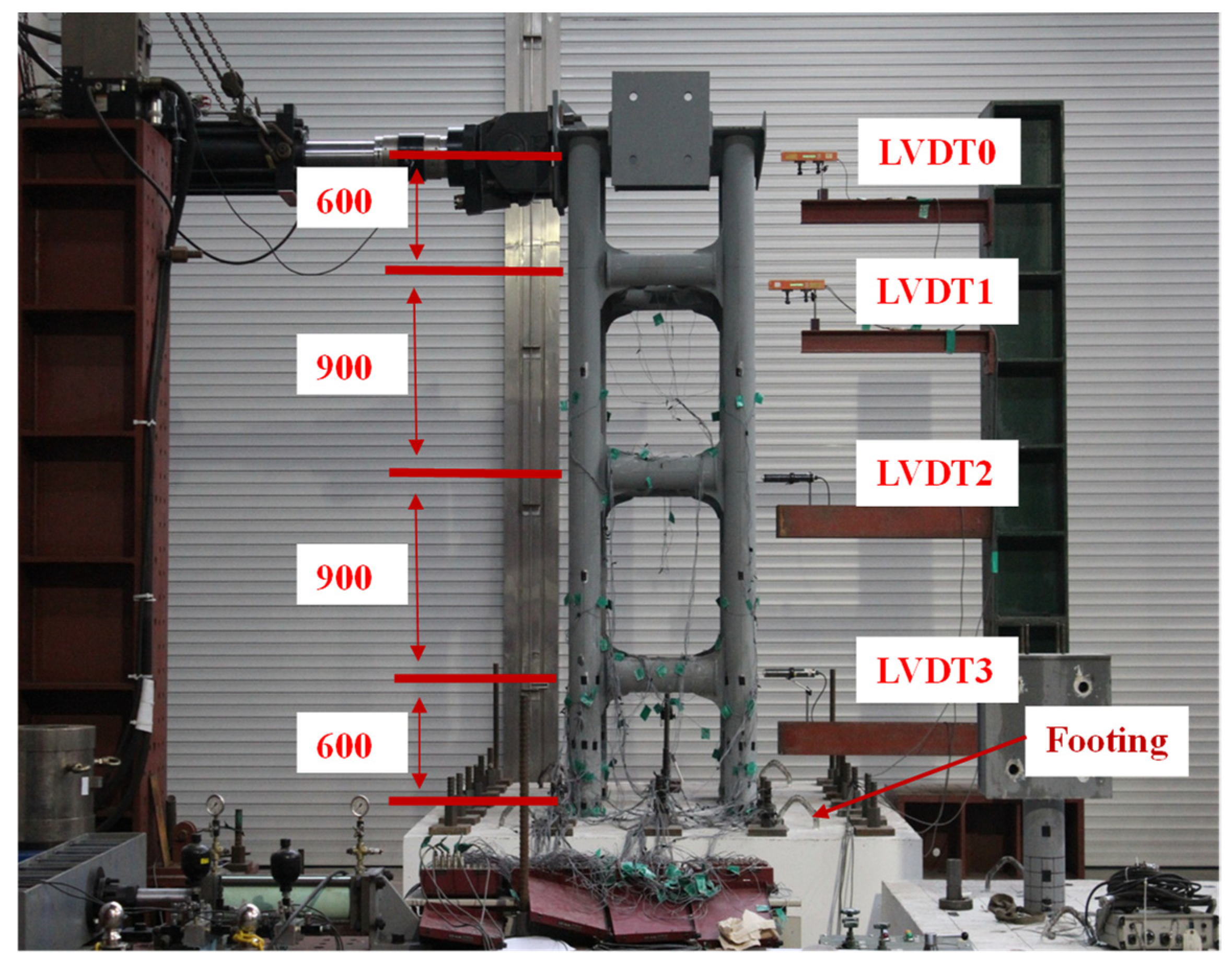
The proposed modular bridge pier must have connections with adequate strength and ductility to prevent premature failure. In a preliminary study, a small-scale modular bridge pier (SMP) specimen with a height of 3.0 m was fabricated with robust bracings, as shown in Figure 2 [25,26]. Four CFT columns were integrated using three-layered bracings, with distances of 1000 mm and 800 mm in the strong and weak axis directions, respectively. The circular steel tube utilized was a commercial product with dimensions of Φ165.2 × 6 × 1072 mm (external diameter × thickness × length). The CFT columns and bracings were welded together, with the CFT columns embedded in the footing and fixed on a strong floor. No axial loading was applied during the tests.
The concrete utilized for the CFT infill had an average compressive strength of 37.0 MPa, determined through the concrete cylinder test. According to the product specifications, the steel had a yield strength of 235 MPa and a tensile strength of 400 MPa. Strain gauges were attached to measure the general strain, including the elastic and plastic strains, at the connections between the columns and bracings and at the bottom of the columns. As shown in Figure 2, cyclic lateral loads were applied to the top floor in the direction of the strong axis, with linear variable-displacement transducers (LVDTs) installed at each floor level.
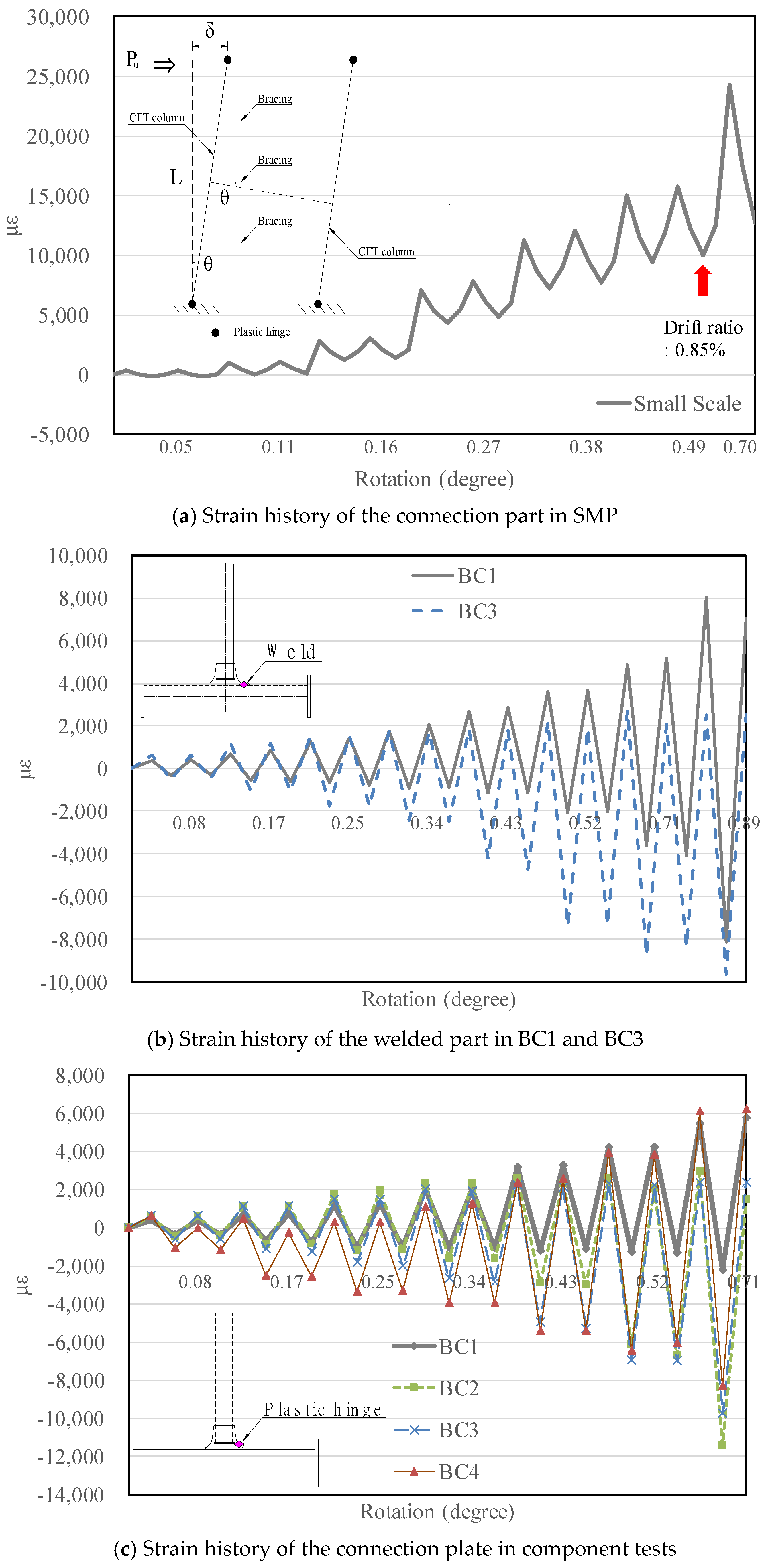
The goal of this system was for the bracings to dissipate sufficient energy and maintain structural integrity without failure until sufficient ductile behavior was achieved after the yielding of the CFT column. However, during the cyclic tests, cracking was observed at the weld between the CFT columns and bracings, as shown in Figure 3a. Strain measurements at the connections indicate the residual strain accumulated with each load cycle, as shown in Figure 3b. The occurrence of low-cycle fatigue failure before the yielding of the CFT columns resulted in inadequate ductile behavior, highlighting the need to investigate enhanced connection details for modular bridge piers to prevent premature failure and ensure optimal seismic performance of bridge sub-structures.

3. Experiments on Connections

Azizinamini et al. [20] investigated various types of moment connections for circular CFT columns, revealing improved flexure and shear behavior when the flange or both the flange and web of the bracing were continuous through the CFT column. These details demonstrated relatively stable inelastic behavior. However, their complexity makes them unsuitable for the rapid construction of modular structures on-site. Therefore, component tests using small-scale CFT columns and bracings with different connection types were planned to assess the moment–curvature relationship, strain development, and cyclic performance.

3.1. Connection Test Specimen

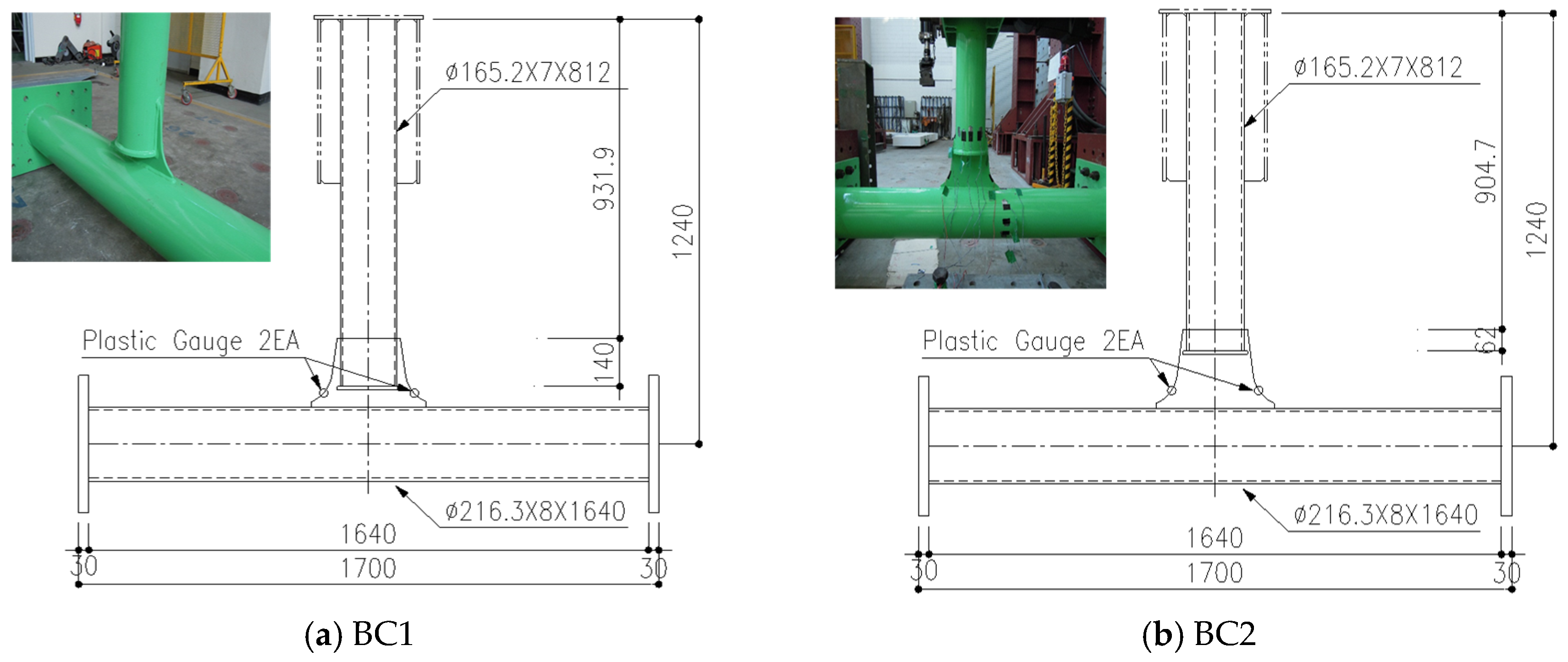
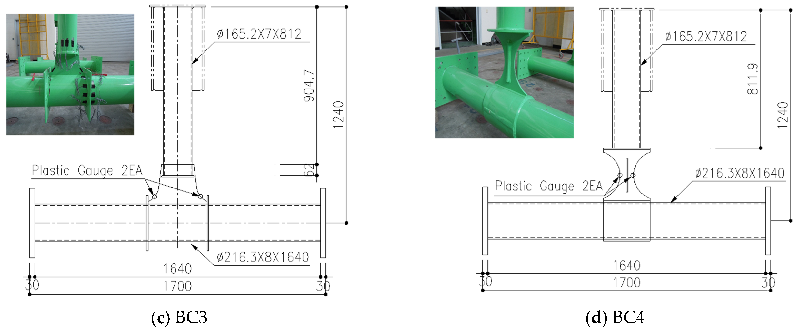
Four types of connections between a CFT column and bracing were designed to evaluate displacement ductility and energy dissipation capabilities. These connections, shown in Figure 4, vary in detail to account for the height of the connection area and shape of the detail. Specimens BC1 and BC2 were designed to evaluate the displacement ductility and energy dissipation of connections based on height, whereas BC3 featured specific details to prevent buckling and disperse the stress concentration at welding part. BC4 incorporated a dog bone-shaped detail to induce an earlier plastic hinge at the connection detail. The steel tubes utilized for the columns and bracing had a yield strength of 315 and a tensile strength of 490 Mpa. The dimensions of the concrete in-filled and bracing steel tubes were Φ 216.3 × 8 × 1640 mm and Φ 165.2 × 7 × 1072 mm, respectively.
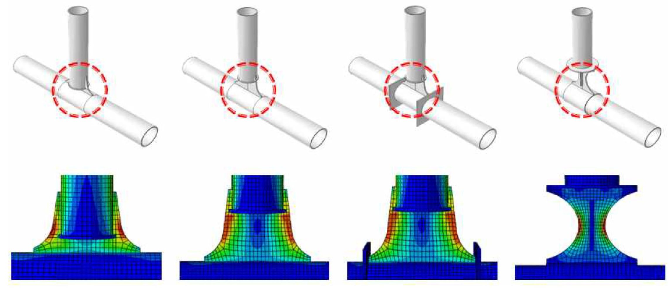
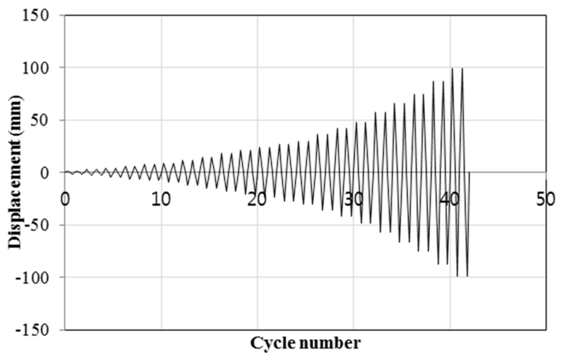
The setup for the component test was designed to simulate the rotational behavior of the bracing by securing both ends of the CFT column, as shown in Figure 5. To identify the location of plastic hinges and determine the location of gauges, finite element analysis was conducted, as shown in Figure 6 before experiments, and it was confirmed that the plastic hinge occurred at the connection plates. Accordingly, the gauges were attached as shown in Figure 5b. PS denotes the plastic strain gauge with a measurement limit of 50,000ε. A and B denote the normal strain gauges attached to the braces and CFT columns, respectively. The loading program was defined considering gradual increase in drift ratio, as shown in Figure 7 and Table 1. Loading was applied at a height of 1000 mm from the center of the CFT column and maintained until bracing failure occurred. Displacement control was implemented by increasing the lateral displacement, utilizing an actuator with a capacity of 1000 kN.

3.2. Connection Test Results

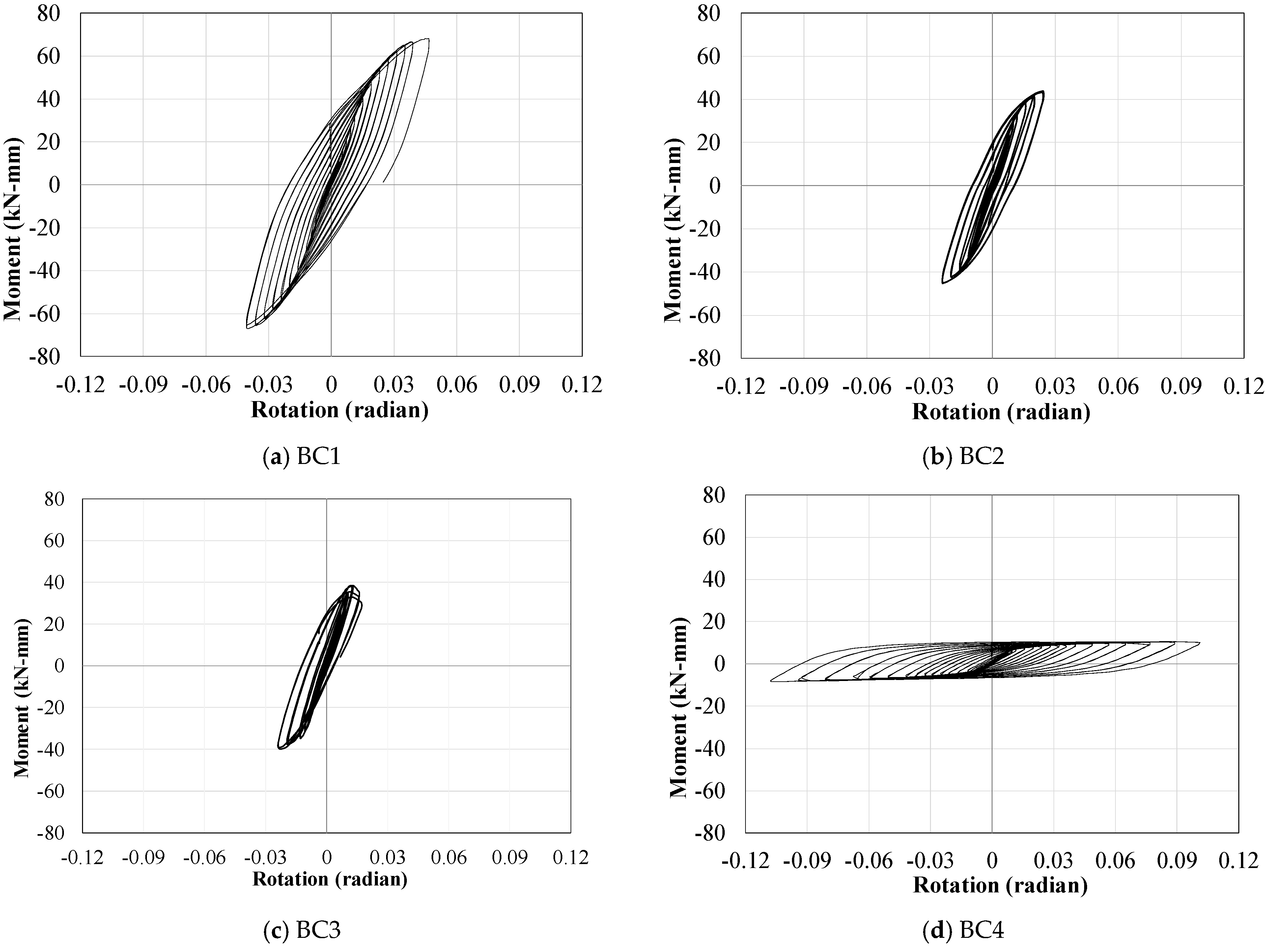
The moment–rotation curves of each specimen are shown in Figure 8, and the experiment results, including maximum load, displacement, energy absorption, and failure modes, are listed in Table 2. The displacements were measured when the loads reached their peak, and the energy absorption was calculated by integrating the hysteresis curves in Figure 8.
BC1 experienced premature failure owing to fatigue at 0.045 rad, displaying elastic behavior up to a lateral displacement of 4.86 mm before a fracture at the connection occurred at a displacement of 32.94 mm, with a maximum load of 93.20 kN. The energy absorption was 8580.68 kJ. BC2, with a connection of 105 mm longer than that of BC1, exhibited lateral buckling at a rotation of 0.024 rad without plastic hinge yielding, reaching a maximum displacement and load of 17.66 mm and 59.95 kN, respectively. The energy absorption was 5244.23 kJ which was a 38.88% decrease from BC1. BC3 was reinforced with stiffening plates from BC2 to enhance the circular tube section at the connection part. Local buckling was also observed on the connection plate when the curvature was 0.012 rad; however, plastic hinge yielding was observed. The maximum load was 52.39 kN, with both elastic and plastic behaviors observed in the lateral displacement up to 7.16 mm and 17.54 mm, respectively. The energy absorption was 1850.88 kJ. BC4 featured a dog bone-shaped detail design to induce a plastic hinge at the bracing member. Stiffeners with proper flexural stiffness were welded to this detail to prevent local buckling. While failure owing to fatigue at the connection point was not observed, plastic behavior was initiated at a curvature of 0.106 rad. The specimen demonstrated ductile behavior until 74.44 mm of lateral displacement, with a maximum capacity of 14.14 kN.
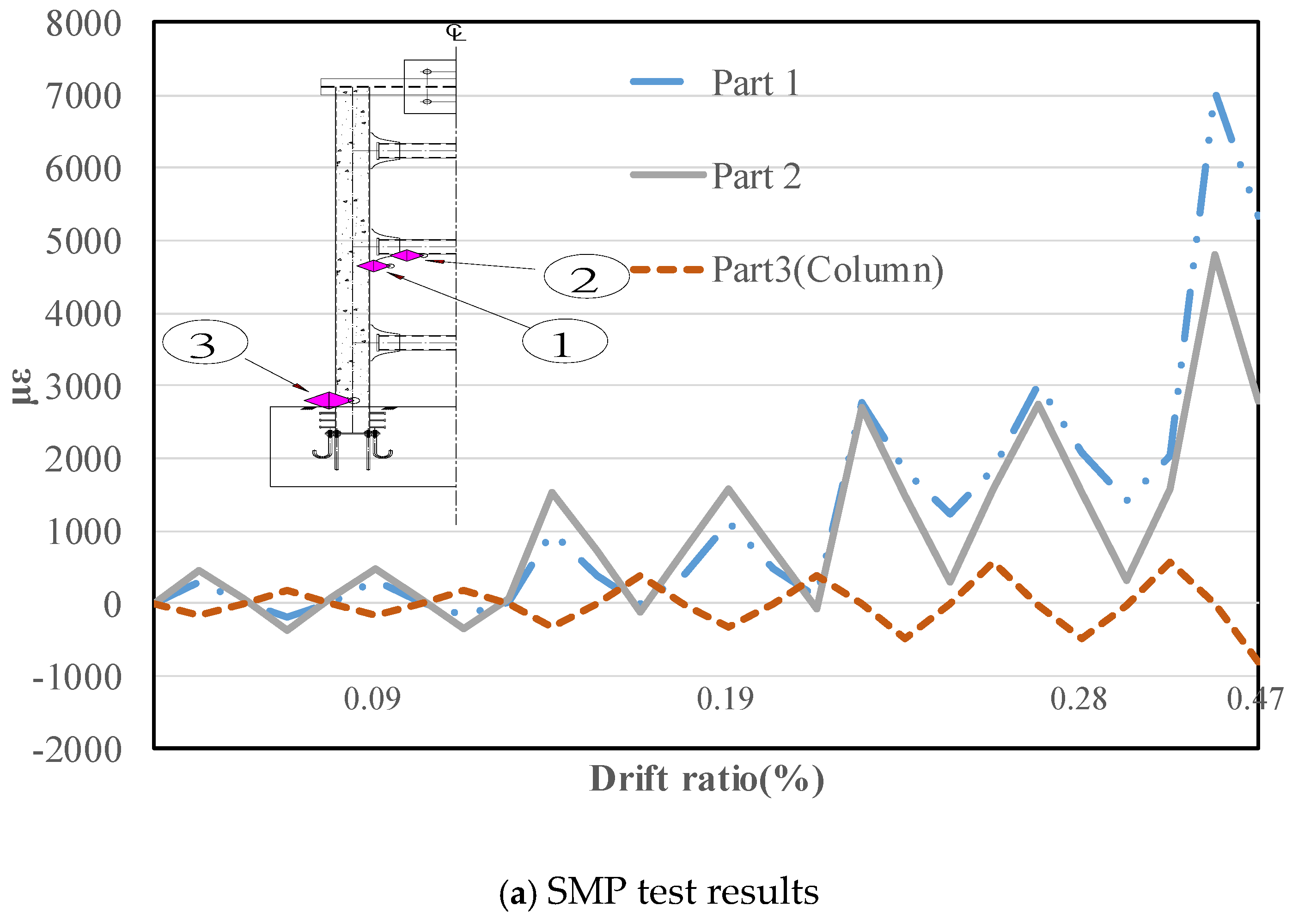
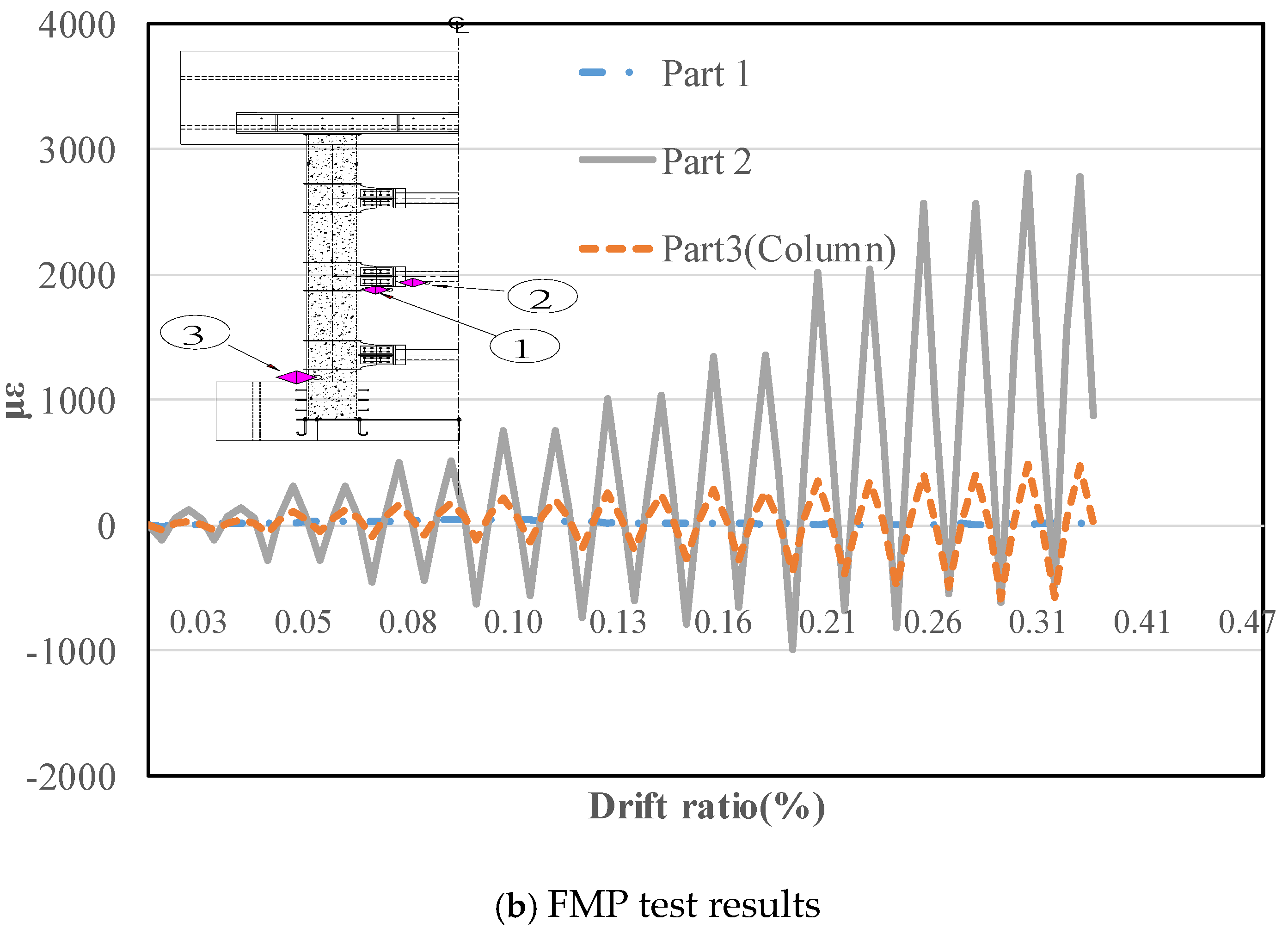
Utilizing the test results of the SMP shown in Figure 3b, the rotation of the bracing was calculated by assuming a linear relationship between the lateral displacement and rotation. The strain history is based on the rotation from the lateral displacement of the SMP. The drift ratio is defined as the ratio of maximum lateral drift to the total height of the specimen. The strain history of the connection plate for all specimens based on the rotation of the bracing is shown in Figure 9. BC1 demonstrated a lower strain at the connection plate compared with that at the welded part of the column, resulting in column fracture. This observation highlights the importance of considering stress concentration in the bracing connection to achieve the necessary drift ratio for modular piers. In other words, initiating plastic deformation at the connection plate is crucial to prevent CFT column fractures.
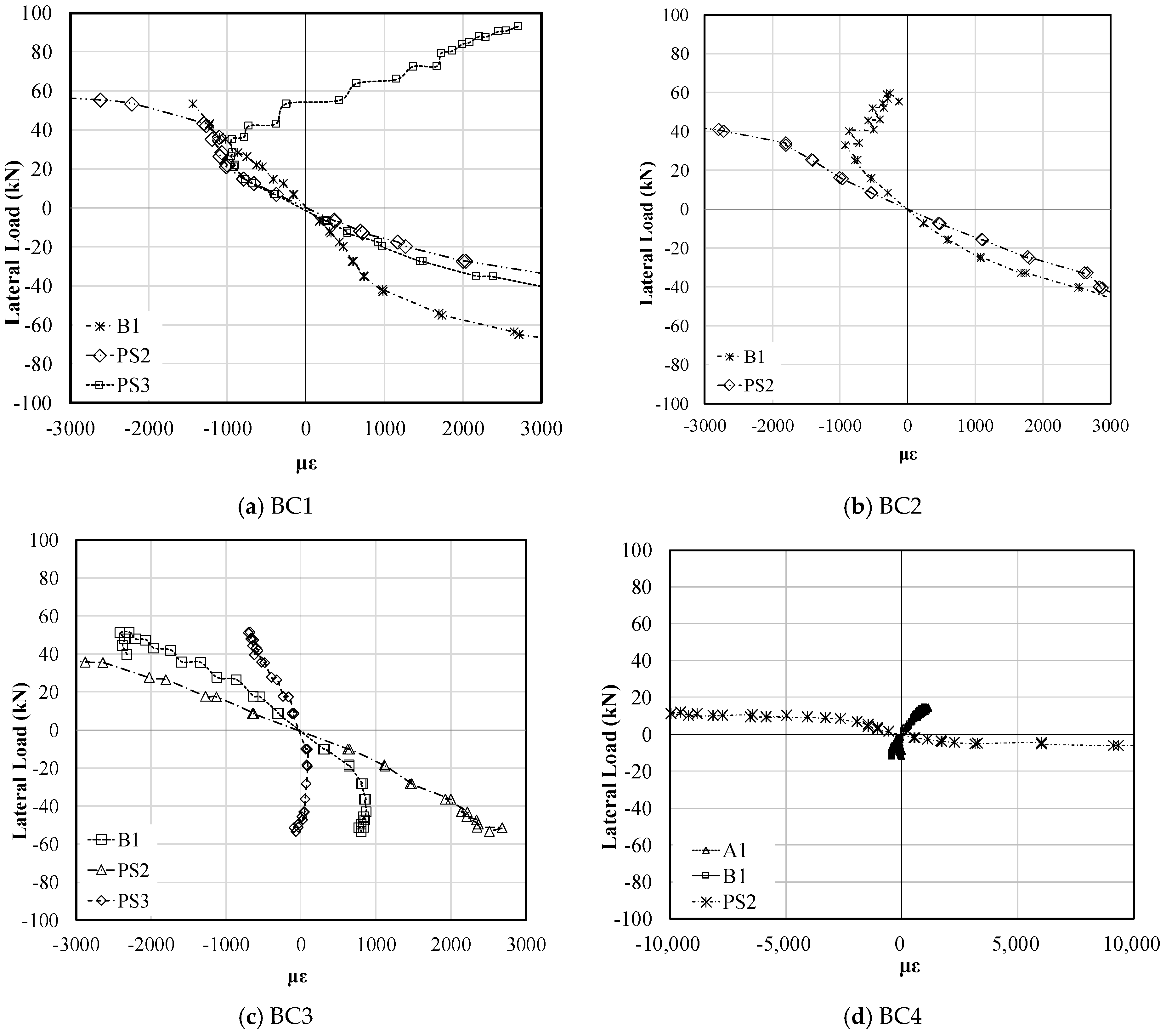
Detailed local behaviors are represented by strain envelope curves in Figure 10. As shown in Figure 5b, PS1 denotes the strain gauge at the weld part, whereas PS2 and PS3 denote the strain gauges at the plastic hinge. The strain envelope curves for the weld, plastic hinge, and bracing members of BC1 are shown in Figure 10a. A fracture was observed at the weld part (PS3) at 950 µε and a load of 27.2 kN. At the same load, the plastic hinge (PS2) and bracing member (B1) exhibited strains of 1000 and 7500 µε, respectively. Gauge PS3 exhibited an apparent fracture in the welded part. The strain envelope curves of BC2 are shown in Figure 10b, displaying a behavior similar to that of BC1, except for the bracing member (B1). Buckling was observed at a plastic hinge (PS2) at a measured strain of 920 µε and a load of 32.89 kN, indicating that buckling occurred before yielding the plastic hinge. The strain envelope curves for BC3 are shown in Figure 10c. During the test, both the bracing member (B1) and plastic hinge (PS2) reached yield strain (1500 µε), whereas the welded part (PS3) remained within the elastic range. The plastic hinge yielded earlier than the bracing member when the load was 28.13 kN. The strain envelope curves of BC4 demonstrated apparent plastic hinge behavior, as shown in Figure 10d. The yield strain of the connection part was reached at a load of 6.62 kN with no damage. The observed behavior of the connections suggests that the location of plastification in the connection can be designed by altering the details.
In summary, although increasing the stiffness of the connecting plate can improve the energy absorption capacity, it can cause stress concentration in the CFT column, which may cause the main member to fail first. Therefore, details that concentrate the stress in the connecting plate are required, and BC3, which shows the yield of the connection before buckling occurs, can be considered as the most suitable detail for protecting the main member, even though it has the lowest energy absorption capacity. Therefore, the connection detail of BC3 was selected for a full-scale modular pier specimen.

4. Experiments on Full-Scale Modular Bridge Pier

Based on the findings of the SMP and component tests in Section 3, a full-scale modular bridge pier (FMP) specimen was designed and fabricated with enhanced bracing details similar to those of BC3. Furthermore, the FMP featured stiffening plates at the end of the weld on the CFT columns, with the bracings and CFT columns bolted together using gusset plates. The primary objective of the cyclic tests was to induce yielding at the bracing connection without premature failure of the CFT columns and ensure stable inelastic behavior.

4.1. Full-Scale Test Specimen

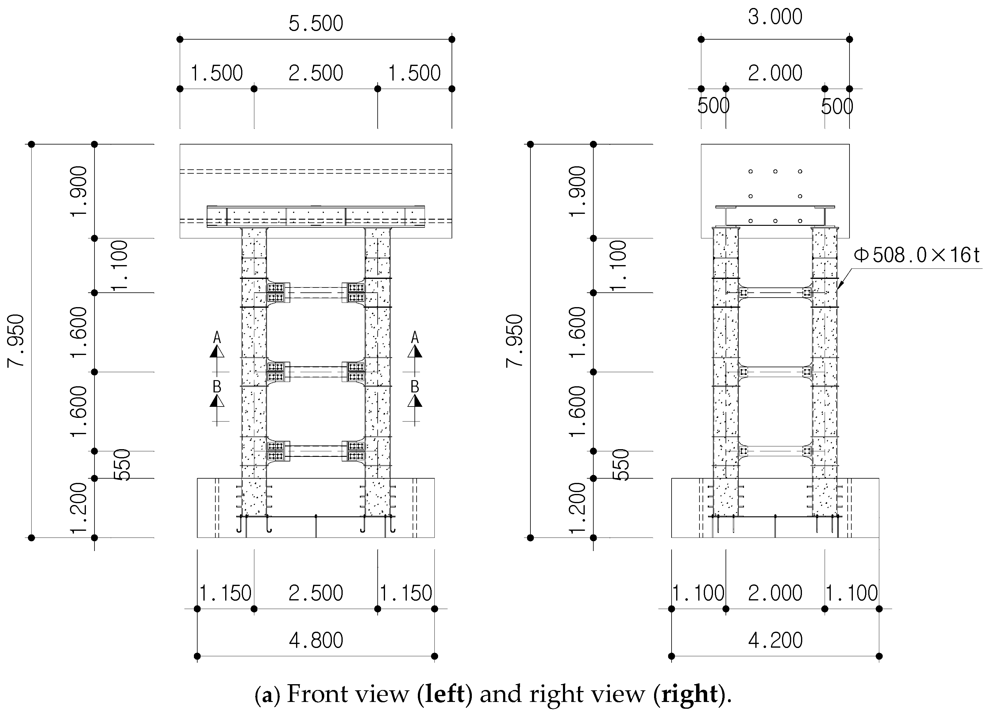
The specimen comprised a pier cap, four concrete-filled tube columns, and three layers with twelve bracings (six on the strong axis and the remaining on the weak axis). The height of the specimen was 7950 mm, as shown in Figure 11a. The column module had a length of 5830 mm, including the column embedded in the foundation. The circular steel tube utilized was a commercial product with dimensions of Φ508.2 × 16 mm, and the D/t ratio of the steel column was 17, satisfying the design provisions for local stability constraints (Table 3). The longitudinal and transverse spacing of the columns were 2500 mm (strong axis) and 2000 mm (weak axis). The bracing members were hollow steel tubes with a diameter of 216.3 mm and a thickness of 7 mm. The embedded length of the CFT columns into the footing concrete was 770 mm, equivalent to 1.5 times the CFT column diameter. The end plate and anchoring details at the end of the embedded column had a sufficient embedment length for the connection to prevent shear failure of the footing concrete and pulling out. The pier cap had a width of 5500 mm, length of 3000 mm, and height of 1900 mm, and transferred the weight of the superstructure to the column. To prevent stress concentration owing to the superstructure weight, a composite cross-section was constructed by applying a steel frame and reinforcing the cross-sectional structure to the pier cap. The dimensions of the steel structure were 4400 × 407 × 428 mm (length × flange width × height). The flange and web thicknesses were 35 and 20 mm, respectively.
The concrete compressive strengths of the design and cylinder tests (average) were 40 and 42 MPa, respectively. The structural steel tubes of the circular CFT columns and bracing exhibited yield and tensile strengths of 315 and 490 MPa, respectively. Each connection between the bracing and column members utilized 16 bolts with a tensile strength of 352.5 kN, as shown in Figure 11c.
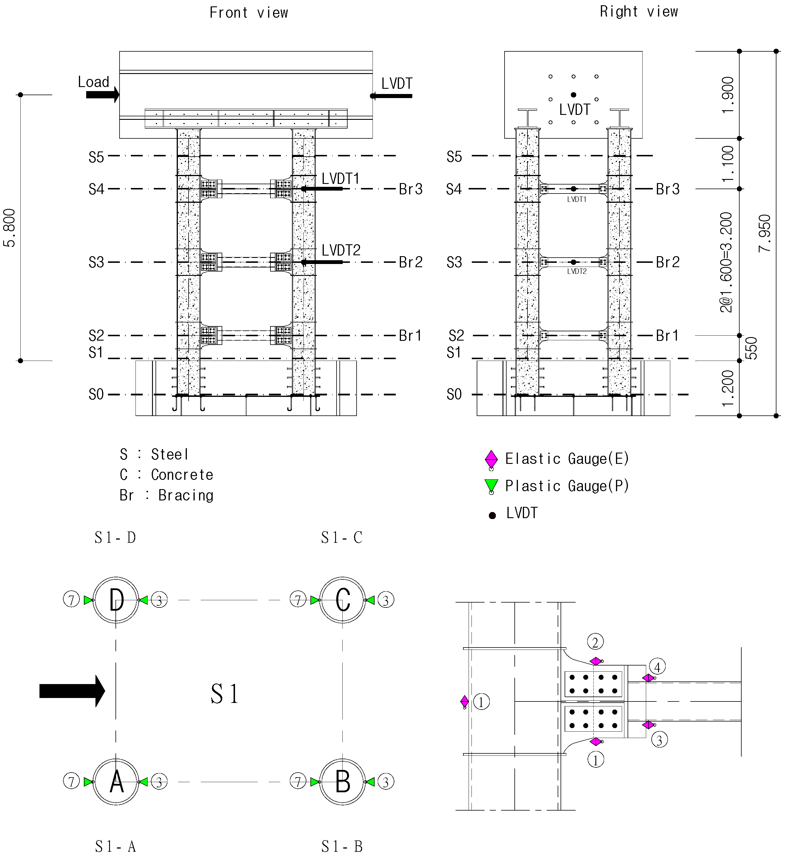
The placement of strain gauges on the bracings and columns at various height levels is shown in Figure 12. S0 represents the lowest level of the CFT columns embedded in the footing, whereas S1 signifies the plastic hinge region of the CFT columns. S2, S3, and S4 denote the bracing levels. S5 represents the middle height of the top floor of the CFT column. Eight strain gauges were affixed to the CFT columns at levels S0, S1, and S5. Additionally, ten strain gauges were attached to the connection parts of the bracings at levels S2, S3, and S4.
The test setup and loading protocols are presented in Figure 13 and Table 4, respectively. A cyclic load, reaching up to 90% of the elastic limit, was applied using an actuator with a capacity of 3000 kN to the pier cap at a height of 5800 mm. The dead weight of the pier cap module exerted compression on the CFT columns, equivalent to 1.8% of the compressive strength of the section. The lateral cyclic load was applied to the center of the pier cap, with the drift ratio increasing at a speed of 1.8 mm/min within the range of 0.03–0.31% from 1 to 17.

4.2. Full-Scale Test Results

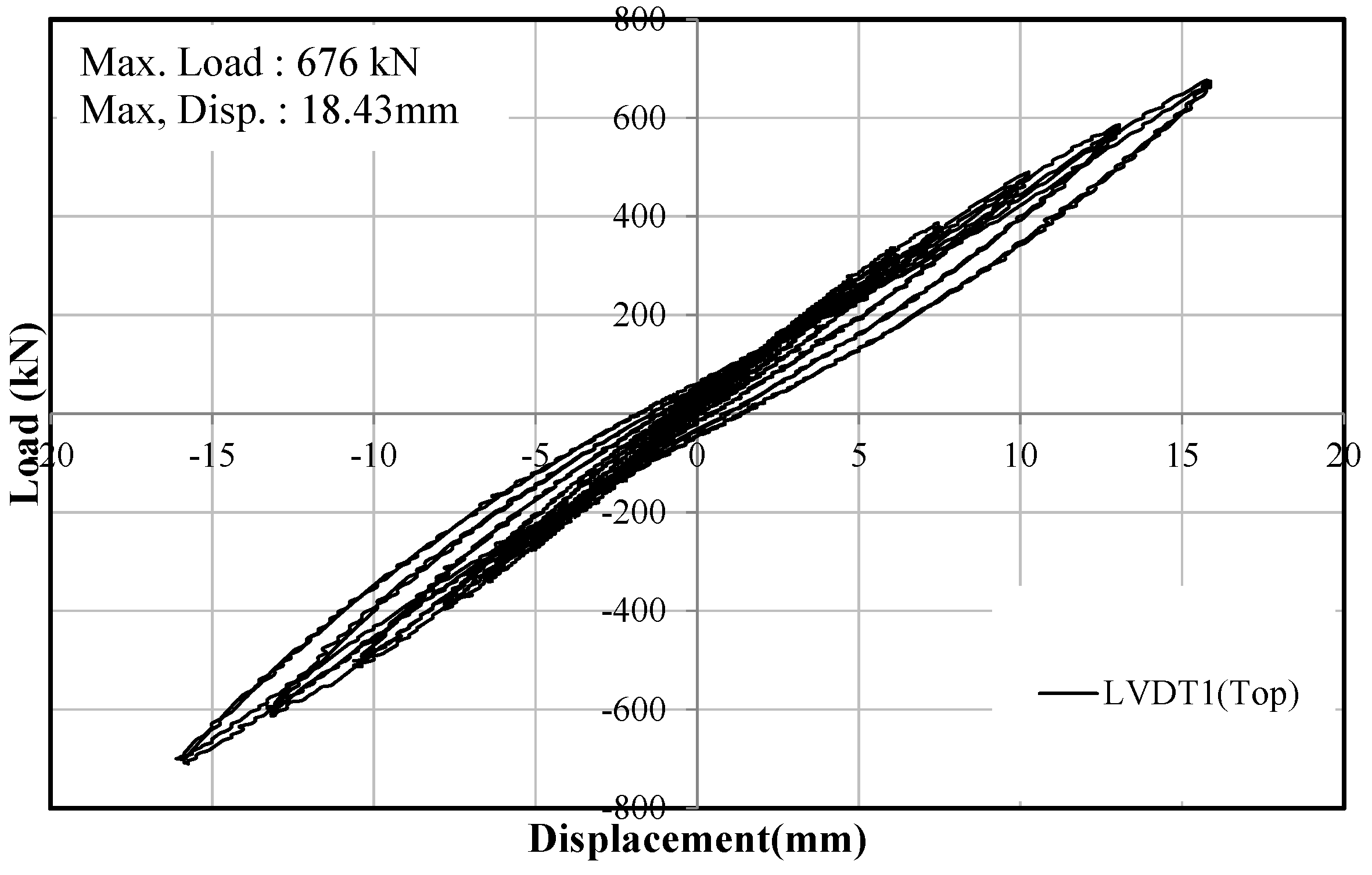
The load–displacement hysteresis curves are shown in Figure 14. Despite the applied maximum load of 676 kN falling within the elastic behavior range of the columns, a slight nonlinear behavior was observed in the curve. A symmetric hysteresis curve was observed, with a maximum lateral displacement of 18.43 mm.
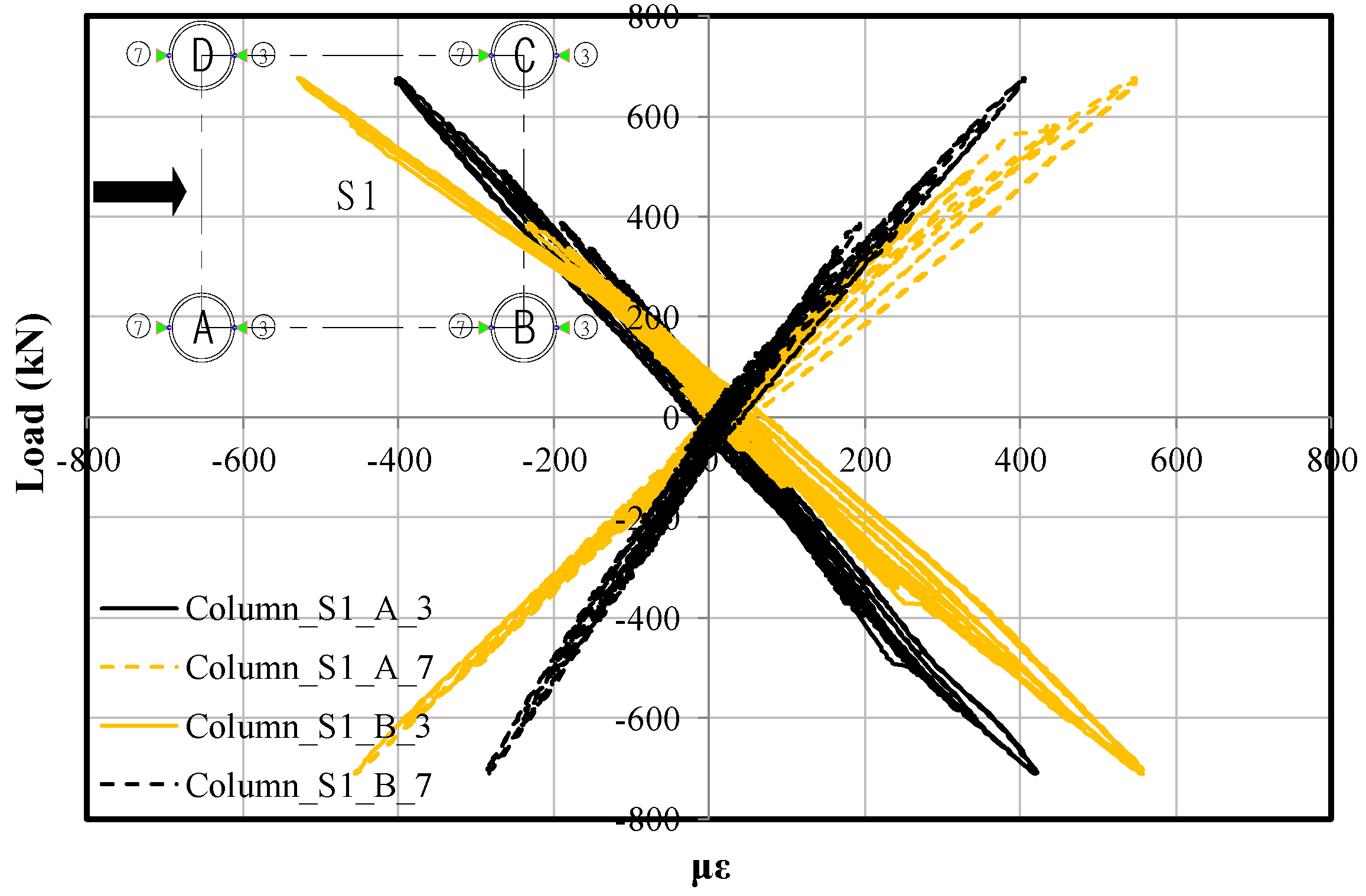
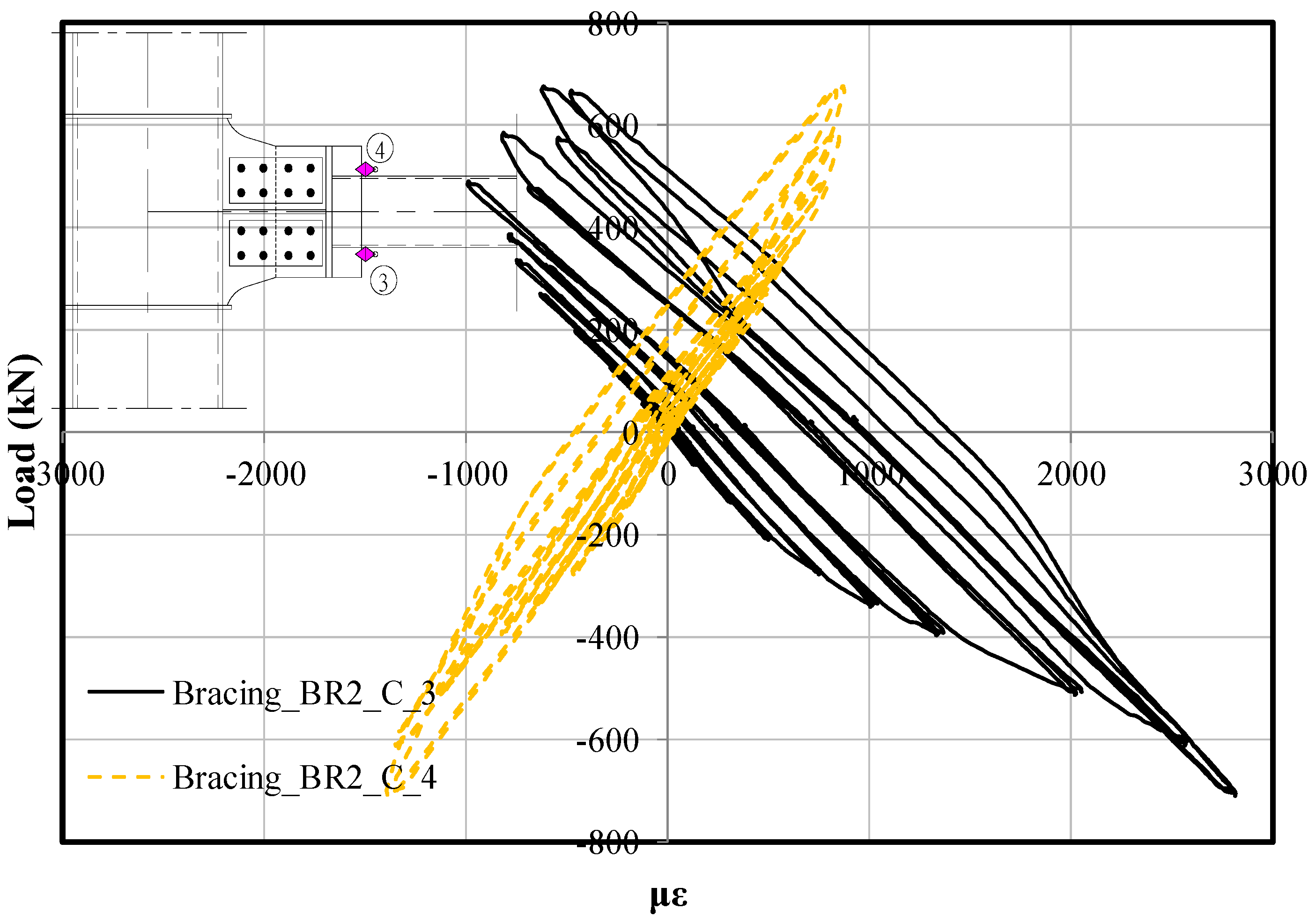
The load–strain curves of the CFT columns at the bottom level are shown in Figure 15. The anticipated yield strain of the CFT column was 1500 με, with negligible residual strain at the bottom level. A higher strain was observed at the BR2 bracing (S2 level) compared with the column strain at the bottom level.
The strain distribution of the bracing connection at BR2 (S2 level) is shown in Figure 16. The residual strain of the bracing connection exceeded that of the CFT column (bottom level). Yield strain was observed at the bracing, resulting in enhanced energy absorption capacity of the modular pier.

4.3. Comparison of the Full- and Small-Scale Specimens

The strain history of the CFT column and the bracing connection at the second-level bracing are shown in Figure 17. For both specimens, the strain values at the bottom of the CFT columns were lower than those at the connection parts. Improved connection details enhanced stress concentration at the welded part of the connection. The FMP specimen exhibited significantly smaller strain values compared with the SMP specimen, suggesting the possibility of initiating the yielding of the bracing members before the CFT columns without premature fractures.

5. Conclusions

Modular bridge substructures comprise numerous connections between modules, with bracing members integrating CFT columns to enhance seismic performance. This study proposed an experimental program that addressed the issue of low-cycle fatigue failure in bracing connections, including component and full-scale tests. The following conclusions were drawn from the test results:
(1)
The connection plates welded to the CFT columns must be made more flexible by extending the plate length to prevent premature fracture of the steel tubes at the welding site.
(2)
The moment–rotation curves derived from the component tests can be utilized to design a modular pier with a dog bone-shaped flexible bracing member, which offers greater strength compared with stiffer bracing. The plastification location in the connection can be designed by altering the details to achieve the desired behavior.
(3)
Enhanced connection details significantly decreased the stress concentration at the welded section of the connection, improving the energy absorption capacity of the modular pier. The full-scale modular pier demonstrated lower strain values compared with the previous stiffer bracing connection specimen, allowing for the initiation of the yielding of the bracing members before the CFT columns without premature fracture. Therefore, the seismic performance of the modular pier can be designed by adjusting the bracing members and their connection details.
Although the effects of size and material properties on CFT columns are not considered in this study, their influence is undoubtedly significant. While many existing studies have investigated these effects on single CFT columns, it remains uncertain whether their findings are applicable to the complex behavior of the multi-column CFT piers and bracing connections presented in this study. In addition, this study presents a rough connection design, and the results may vary depending on the materials used and the connection details not considered. For example, the same steel grade was used for the bracing and CFT columns in this study, but if different steel grades were used, the connection stress development patterns may be different. In order to present a connection detail-design standard that reflects various actual field conditions, an in-depth study on the connection details of CFT columns for piers should be conducted. Therefore, future research is needed to verify these effects for rational design.

Author Contributions

Conceptualization, D.K.; methodology, D.K.; validation, D.K. and C.-H.J.; formal analysis, D.K. and C.-H.J.; investigation, D.K. and C.-H.J.; resources, D.K. and C.-H.J.; data curation, D.K. and C.-H.J.; writing—original draft preparation, D.K.; writing—review and editing, D.K. and C.-H.J.; visualization, D.K. and C.-H.J.; funding acquisition, K.-T.P. All authors have read and agreed to the published version of the manuscript.

Funding

This research was carried out under the KICT Research Program (project no. 20240142-001, Development of DNA-based smart maintenance platform and application technologies for aging bridges) funded by the Ministry of Science and ICT.

Institutional Review Board Statement

Not applicable.

Informed Consent Statement

Not applicable.

Data Availability Statement

All data, models, and code generated or used during the study appear in the published article.

Conflicts of Interest

Author Dongwook Kim was employed by the company DL E&C Co., Ltd. The remaining authors declare that the research was conducted in the absence of any commercial or financial relationships that could be construed as a potential conflict of interest.

References

  1. Shim, C.S.; Chung, C.H.; Kim, H.H. Experimental evaluation of seismic performance of precast segmental bridge piers with a circular solid section. Eng. Struct. 2008, 30, 3782–3792. [Google Scholar] [CrossRef]
  2. Shim, C.S.; Chung, Y.S.; Han, J.H. Cyclic response of concrete-encased composite columns with low steel ratio. Proc. Inst. Civ. Eng. Struct. Build. 2008, 161, 77–89. [Google Scholar] [CrossRef]
  3. Shim, C.S.; Chugn, C.H.; Kim, I.K.; Kim, Y.J. Shear connections in prestressed beams with precast slabs. Proc. Inst. Civ. Eng. Struct. Build. 2010, 163, 317–330. [Google Scholar] [CrossRef]
  4. Shim, C.S.; Chung, Y.S.; Yoon, J.Y. Cyclic behavior of prefabricated circular composite columns with low steel ratio. Eng. Struct. 2011, 33, 2525–2534. [Google Scholar] [CrossRef]
  5. Zeghiche, J.; Chaoui, K. An experimental behaviour of concrete-filled steel tubular columns. J. Constr. Steel Res. 2005, 61, 53–66. [Google Scholar] [CrossRef]
  6. Tomii, M.; Sakino, K. Experimental Studies on the Ultimate Moment of Concrete Filled Square Steel Tubular Beam-Columns. Trans. Archit. Inst. Jpn. 1979, 275, 55–65. [Google Scholar] [CrossRef] [PubMed]
  7. AISC. Specification for Structural Steel Buildings; American Institute of Steel Construction: Chicago, IL, USA, 2005. [Google Scholar]
  8. BSI. Eurocode 4: Design of Composite Steel and Concrete Structures—Part 1-1: General Rules and Rules for Buildings; British Standards Institution: London, UK, 2004. [Google Scholar]
  9. Nishiyama, I.; Morino, S.; Sakino, K.; Nakahara, H.; Fujimoto, T.; Mukai, A.; Inai, E.; Kai, M.; Tokinoya, H.; Fukumoto, T.; et al. Summary of research on concrete-filled structural steel tube column system carried out under the US–Japan cooperative research program on composite and hybrid structures. Build. Res. Inst. 2002. [Google Scholar]
  10. Tsuda, K.; Matsui, C.; Mino, E. Strength and Behavior of Slender Concrete Filled Steel Horizontal load. In Proceedings of the 12th World Conference on Earthquake Engineering, Auckland, New Zealand, 30 January–4 February 2000. [Google Scholar]
  11. Xu, Q.; Sun, H.; Ding, F.; Lyu, F. Analysis of ultimate seismic performance of thin-walled concrete-filled steel tube bridge piers under dynamic load. Eng. Struct. 2023, 292, 116544. [Google Scholar] [CrossRef]
  12. Zhang, H.S.; Zhao, Y.; Ruan, J.; Nie, X.; Fan, J.S.; Liu, Y.F. Experiment study on temperature field and effect on steel-concrete composite bridge towers. Structures 2023, 50, 937–953. [Google Scholar] [CrossRef]
  13. Li, X.; Zhang, Z.; Zhou, T.; Xiao, Y.; Sun, Y. Hysteretic behavior of post-tensioned precast segmental CFT double-column piers. Earthq. Eng. Eng. Vib. 2023, 22, 747–762. [Google Scholar] [CrossRef]
  14. El-Heweity, M.M. On the performance of circular concrete-filled high strength steel columns under axial loading. Alex. Eng. J. 2012, 51, 109–119. [Google Scholar] [CrossRef]
  15. de Oliveira, W.L.A.; De Nardin, S.; de Cresce El Debs, A.L.H.; El Debs, M.K. Influence of concrete strength and length/diameter on the axial capacity of CFT columns. J. Constr. Steel Res. 2009, 65, 2103–2110. [Google Scholar] [CrossRef]
  16. Roeder, C.W.; Lehman, D.E.; Thody, R. Composite action in CFT components and connections. Eng. J. 2009, 46, 229–242. [Google Scholar] [CrossRef]
  17. Lehman, D.E.; Roeder, C.W. Foundation connections for circular concrete-filled tubes. J. Constr. Steel Res. 2012, 78, 212–225. [Google Scholar] [CrossRef]
  18. Kim, H.J.; Hu, J.W.; Hwang, W.S. Cyclic testing for structural detail improvement of CFT column-foundation connections. Sustainability 2015, 7, 5260–5281. [Google Scholar] [CrossRef]
  19. Moon, J.; Lehman, D.E.; Roeder, C.W.; Lee, H. Evaluation of embedded concrete-filled tube (CFT) column-to-foundation connections. Eng. Struct. 2013, 56, 22–35. [Google Scholar] [CrossRef]
  20. Azizinamini, A.; Schneider, S. Moment connections to circular concrete-filled steel tube columns. J. Struct. Eng. 2004, 130, 213–222. [Google Scholar] [CrossRef]
  21. MacRae, G.; Roeder, C.; Gunderson, C.; Kimura, Y. Brace-Beam-Column Connections for Concentrically Braced Frames with Concrete Filled Tube Columns. J. Struct. Eng. 2004, 130, 233–243. [Google Scholar] [CrossRef]
  22. Hassan, M.M.; Ramadan, H.M.; Abdel-Mooty, M.N.; Mourad, S.A. Behavior of concentrically loaded CFT braces connections. J. Adv. Res. 2014, 5, 243–252. [Google Scholar] [CrossRef] [PubMed]
  23. Wang, J.; Li, B. Seismic fragility analysis of CFT frames with buckling-restrained braces and steel braces under long- and short-duration ground motions. Structures 2022, 39, 848–865. [Google Scholar] [CrossRef]
  24. Mata, R.; Nuñez, E. Cyclic Behavior of Concrete-Filled Tube Columns with Bidirectional Moment Connections Considering the Local Slenderness Effect. Buildings 2024, 14, 2240. [Google Scholar] [CrossRef]
  25. Shim, C.; Kim, D.; Jung, D.; Kim, I.; Chung, C. Cyclic Tests of Modular CFT Bridge Piers. In Proceedings of the 10th National Conference in Earthquake Engineering, Anchorage, AK, USA, 21–25 July 2014; Earthquake Engineering Research Institute: Anchorage, AK, USA, 2014. [Google Scholar]
  26. Ma, H.W.; Oh, H.C.; Kim, D.W.; Kong, D.; Shim, C.S. Evaluation of Flexural Behavior of a Modular Pier with Circular CFT. J. Korean Soc. Steel Constr. 2012, 24, 725–734. [Google Scholar] [CrossRef]
  27. AASHTO. LRFD Bridge Design Specifications, 5th ed.; American Association of State Highway and Transporta-tion Officials: Washington, DC, USA, 2010. [Google Scholar]
  28. ACI Committee, 318. Building Code Requirements for Structural Concrete and Commentary; American Concrete Institute: Detroit, MI, USA, 2011. [Google Scholar]
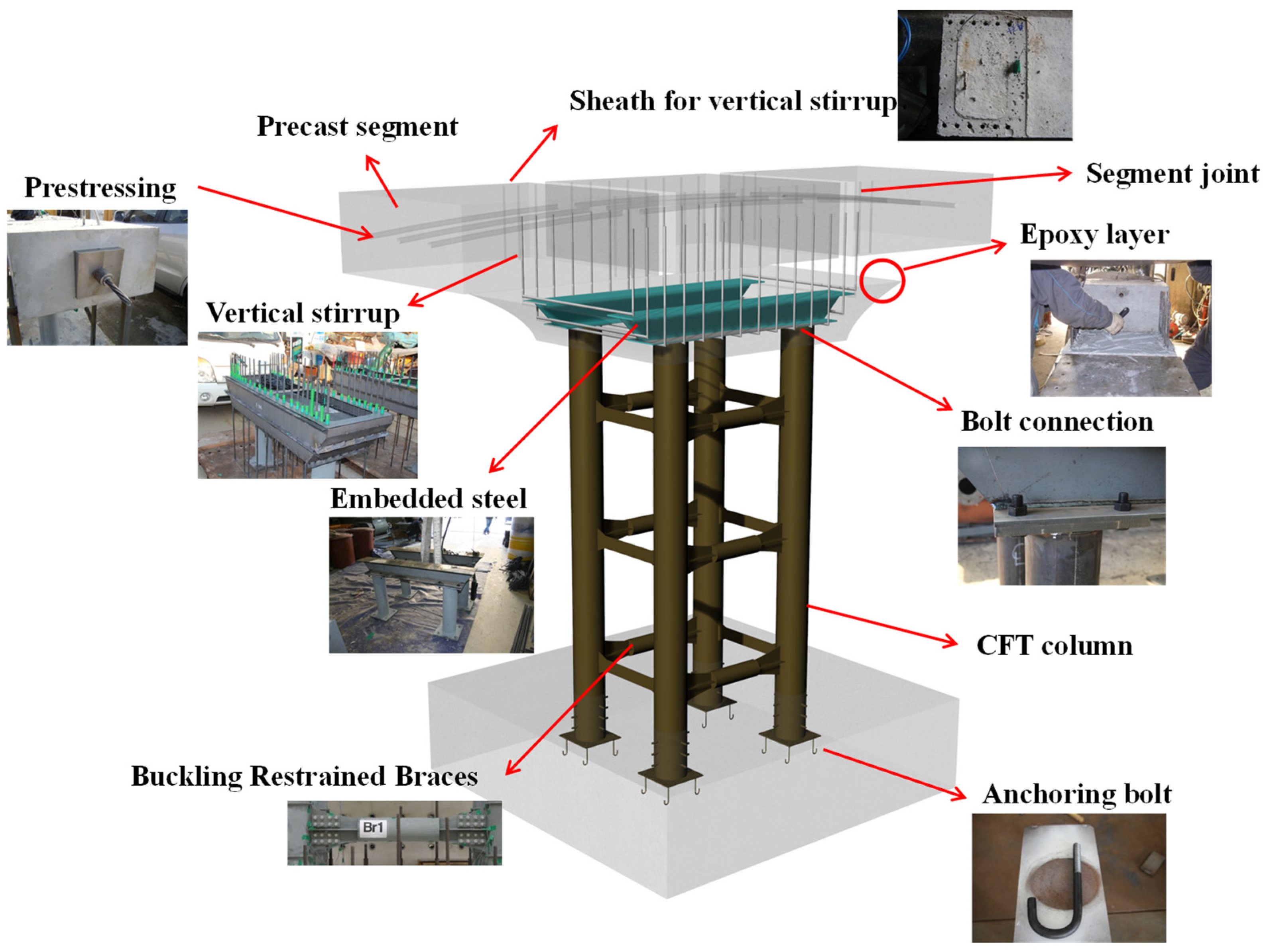
Figure 1. Modular bridge pier.
Applsci 14 11810 g001
Figure 2. Small-scale test specimen of the proposed modular bridge pier.
Applsci 14 11810 g002
Figure 3. Experimental result: (a) Welding fatigue failure owing to stress concentration, (b) stress developments in the bracing connection at the level of LVDT2.
Applsci 14 11810 g003
Figure 4. Test specimens for connection details (unit: mm).
Applsci 14 11810 g004aApplsci 14 11810 g004b
Figure 5. Components test setup.
Applsci 14 11810 g005
Figure 6. Stress contour of connection joints.
Applsci 14 11810 g006
Figure 7. Loading program.
Applsci 14 11810 g007
Figure 8. Moment–rotation curves of the connections.
Applsci 14 11810 g008
Figure 9. Strain history of SMP and component tests.
Applsci 14 11810 g009
Figure 10. Load–strain curve of connection parts.
Applsci 14 11810 g010
Figure 11. Full-scale test specimen for modular CFT pier (unit: mm).
Applsci 14 11810 g011aApplsci 14 11810 g011b
Figure 12. Gauge plan (unit: mm).
Applsci 14 11810 g012
Figure 13. Test setup of the full-scale modular bridge pier.
Applsci 14 11810 g013
Figure 14. Test setup of the full-scale modular bridge pier.
Applsci 14 11810 g014
Figure 15. Load–strain curves of the CFT column (S1 level).
Applsci 14 11810 g015
Figure 16. Load–strain curves of bracing 2-column C joint.
Applsci 14 11810 g016
Figure 17. Comparison of bracing behavior of SMP and FMP.
Applsci 14 11810 g017aApplsci 14 11810 g017b
Table 1. Loading program of the component test.
Cycle1~1213~2627~3233~3839~42
Displacement (mm)±1.5~±9.0±12.0~±30.0±36.0~±48.0±57.0~±75.0±87.0~±99.0
Drift Ratio (%)±0.17~±1.01±1.35~±3.36±4.04~±5.38±6.39~±8.41±9.76~±11.1
Velocity Increment (mm/s)±0.06±0.12±0.24±0.36±0.48
Table 2. Experiment results of connection specimens.
SpecimenMax. Load
(kN)
Displacement
(mm)
Energy Absorption
(kJ)
Failure Mode
BC193.2032.948580.68Fatigue failure of welding part
BC259.9517.665244.23Lateral buckling without plastic hinge yielding
BC352.399.261850.88Lateral buckling after plastic hinge yielding
BC414.1474.444492.59No failure with plastic hinge yielding
Table 3. Loading program for the full-scale test.
Design CodesD/t LimitsTest Specimen
EquationsCalculationCalculation
LRFD (2010) [7,27] 0.11 E s / f y *73.317.0
ACI-318 (2011) [28] 8 E s / f y 73.0
Eurocode 4 (2004) [8] 90 ( 235 / f y ) 67.1
* E s : Elastic modulus of steel (210,000 MPa), f y : Yield strength of steel (315 MPa).
Table 4. Loading program for the full-scale test.
Displacement (mm)±1.5–±18.0
Drift Ratio (%)±0.03–±0.31
Velocity Increment (mm/s)±1.8
Cycle1–17
Disclaimer/Publisher’s Note: The statements, opinions and data contained in all publications are solely those of the individual author(s) and contributor(s) and not of MDPI and/or the editor(s). MDPI and/or the editor(s) disclaim responsibility for any injury to people or property resulting from any ideas, methods, instructions or products referred to in the content.