Article

The Vibro-Acoustic Characteristics Analysis of the Coupled System between Composite Laminated Rotationally Stiffened Plate and Acoustic Cavities

1
Institute of Noise & Vibration, Naval University of Engineering, Wuhan 430033, China
2
College of Mechanical and Electrical Engineering, Nanjing University of Aeronautics and Astronautics, Nanjing 210016, China
3
National Key Laboratory on Ship Vibration & Noise, Wuhan 430033, China
*
Author to whom correspondence should be addressed.
Appl. Sci. 2024, 14(3), 1002; https://doi.org/10.3390/app14031002
Submission received: 3 December 2023 / Revised: 18 January 2024 / Accepted: 19 January 2024 / Published: 24 January 2024

Abstract

:
In order to study vibro-acoustic characteristics between composite laminated rotationally stiffened plate and acoustic cavities in the coupled system, first-order shear deformation theory (FSDT) and modified Fourier series are used to construct a unified analysis model. The involved coupled systems primarily encompass three types: the coupled system between composite laminated rotationally stiffened plate and cylindrical-cylindrical cavities, spherical-cylindrical cavities, and conical-cylindrical cavities. First, the first-order shear deformation theory and the modified Fourier series are applied to construct the allowable displacement function of the composite laminated rotationally stiffened plate and the allowable sound pressure function of the acoustic cavities. Second, the energy functionals for the structural domain and the acoustic field domain are established, respectively. According to the continuity condition of the particle vibration velocity at the coupling boundary between the composite, laminated cylindrical shell and the enclosed cavity, the coupling potential energy between the stiffened plate and two acoustic cavities is introduced to obtain the energy functional of the coupled system. Third, the Rayleigh-Ritz method is utilized to solve the energy functional and, when combined with artificial virtual spring technology, the suggested theory may be used to study the vibro-acoustic characteristics of a coupled system with arbitrary elastic boundary conditions. Finally, based on validating the fast convergence and correctness of the model, this paper will analyze the impact of crucial parameters on vibro-acoustic characteristics. Furthermore, by incorporating internal point forces and point-sound source stimulation, a steady-state response analysis of the coupled system will be conducted. This research can give a theoretical foundation for the vibration and noise reduction of a vibro-acoustic coupling system.

1. Introduction

The composite laminated rotationally stiffened plate has found extensive applications in the aerospace industry. These stiffened plates vibrate under loading, and this vibration interacts with the surrounding airflow, making them a significant source of noise. In practical engineering, creatin a coupled system between composite laminated rotationally stiffened plates and acoustic cavities is unavoidable. The coupling potential energy between the structural domain and the acoustic field domain makes the study of the coupled system’s vibro-acoustic characteristics exceedingly difficult. Simultaneously, a deeper understanding of the structural-acoustic coupling in such coupled systems is crucial for systematic structural optimization and noise control. This is why it is necessary to further study the vibro-acoustic characteristics of the coupled system between a composite laminated rotationally stiffened plate and acoustic cavities.
Currently, some progress has been made in the research of structural-acoustic coupled systems between composite material structures and infinite acoustic fields. Shahraeeni et al. [1] developed an analytical model of the coupled system between piezoelectric laminated plate and acoustic cavities under a simply supported boundary using the classical laminated plate theory and the eigenfunction expansion method. Huang et al. [2] proposed a modelling methodology according to the wave superposition method. They unified the analysis of near-field and far-field regions as a single system, providing a quantitative analysis of how the marine acoustic environment affects the acoustic radiation field of an elastic shell structure, using the example of an elastic spherical shell. Qu and Meng [3] employed an improved variational principle and a multi-level partitioning method to investigate the nonlinear vibration and acoustic radiation responses of laminated plates with skin-core debonding under time-varying loads in an unlimited fluid. Secgin et al. [4] proposed a statistical energy analysis method for complex structural acoustic systems, including point, line, and area connections. This method was used for mid- to high-frequency vibrations and acoustic analysis of box-model-basing modal impedances.
Structural-acoustic coupled systems composed of an infinite sound field cannot analyze specific product objects in engineering practice. As a result, more study on the vibro-acoustic characteristics of coupling systems with finite-sized sound fields is required. In such studies, some researchers have started to establish theoretical models of the coupled system between composite material structures and acoustic cavities using finite element or energy methods. Sarigül and Karagözlü [5] investigated the modal, structural-acoustic coupling properties of plates with different composite material parameters, studying the impact of material properties, layer angles, and the number of layers on the vibro-acoustic characteristics of a composite material plate-cavity coupling system and comparing them to isotropic plate-cavity coupling system. Dozio and Alimonti [6] proposed a novel and advanced finite element formulation for structural-acoustic problems and studied the coupling problem between rectangular composite-material plates and cavities. Sharma et al. [7] studied the vibration and sound responses of hyperbolic laminated plate structures under harmonic point loads and established a structural response simulation model that considered different geometric shapes, such as cylinders, ellipsoids, spheres, and hyperboloids. Balakrishnan et al. [8] numerically evaluated the vibro-acoustic performance of metal-fiber laminated plates with the mid-plane as the center and used finite element methods to study fluid-structure coupling problems.
With the widespread application of stiffened plates in various fields, there is an increasing amount of research on the vibro-acoustic characteristics of the coupled system between a composite laminated stiffened plate and acoustic cavities. Xin and Lu [9] developed analytical models of the wave and sound propagation characteristics of two sets of orthogonal stiffened laminated structures subjected to convective fluid pressure. They checked the accuracy of the analytical model by comparing its predictions to previous findings. Fu and Chen [10] established an analytical model of the sound transmission loss of orthogonal stiffened plate structures under a diffuse sound field. They validated the effectiveness and feasibility of the model by comparing it with experimental results. Zhao [11] conducted a study on the sound excitation of uniformly stiffened plates using an approximate model and compared it with the joint acceptance formula of plane wave harmonic sound excitation.
In summary, while numerous studies have explored the vibro-acoustic characteristics of the coupled system between a composite laminated stiffened plate and acoustic cavities, most of these studies have focused on rectangular stiffened plates. There has been limited research on the coupled system between a composite laminated rotationally stiffened plate and acoustic cavities. Even in cases where rotationally stiffened plates or other complex structures are involved [12], the analysis is often confined to finite element method (FEM) simulations, which may not be conducive to design and practical implementation. This article aims to utilize the modified Fourier series method and first-order shear deformation theory to construct a unified analysis model of the vibro-acoustic characteristics of the coupling system between a composite laminated rotationally stiffened plate and acoustic cavities. Firstly, displacement and sound pressure functions of the coupling system are established by using the modified Fourier series method [13,14]. Subsequently, energy functionals are formulated for both the structural and acoustic domains. Leveraging the coupling characteristics between a composite laminated rotationally stiffened plate and acoustic cavities, a coupling potential energy of the plate-cavity coupling system is defined. This coupling potential energy is then integrated into the energy functional of the coupled system between a composite laminated rotationally stiffened plate and the acoustic cavities to derive the total energy functional of the coupled system. Finally, utilizing the Rayleigh-Ritz energy technique, the extremal values of the coupled system’s energy functional are determined to solve for the vibro-acoustic characteristics. Upon verifying the correctness and convergence of the established coupled system, the correlative parameterization research is carried out. It investigates the effects of crucial parameters such as height of the cylindrical cavity, the apex angle of the spherical cavity, the rotation angle, the cone apex angle of the conical cavity, and the boundary spring stiffness values on the coupling system’s vibro-acoustic characteristics. Furthermore, it examines the impact of external excitation amplitude, the impedance value, and material parameters on steady-state response. This research offers a theoretical direction for the design, vibration control, and noise reduction of similar engineered structures.

2. Modeling of the Unified Analysis Model of Vibro-acoustic Characteristics

2.1. Model Description

This paper establishes a unified analysis model of the vibro-acoustic characteristics of the coupled system between a composite laminated rotationally stiffened plate and the double-cavity structure of cylindrical-cylindrical, spherical-cylindrical, and conical-cylindrical configurations. These systems represent several examples of the coupled system. Because the coupling principles of different structural-acoustic systems are similar, this chapter employs this unified analysis model to analyze the acoustic-vibration characteristics of the coupled system.
Rotational cylinders, spheres, and conical cavities can be represented using a special case of a double-curvature cavity unit. As shown in Figure 1, the unit’s bottom surface (z = 0) is taken as a reference plane for establishing an orthogonal coordinate system. Here, Rα and Rβ represent the base curvature radii along the α and β axes, while Lα and Lβ denote the length dimensions along the α and β axes. Additionally, Lz represents the height dimension of the cavity along the z-coordinate direction.
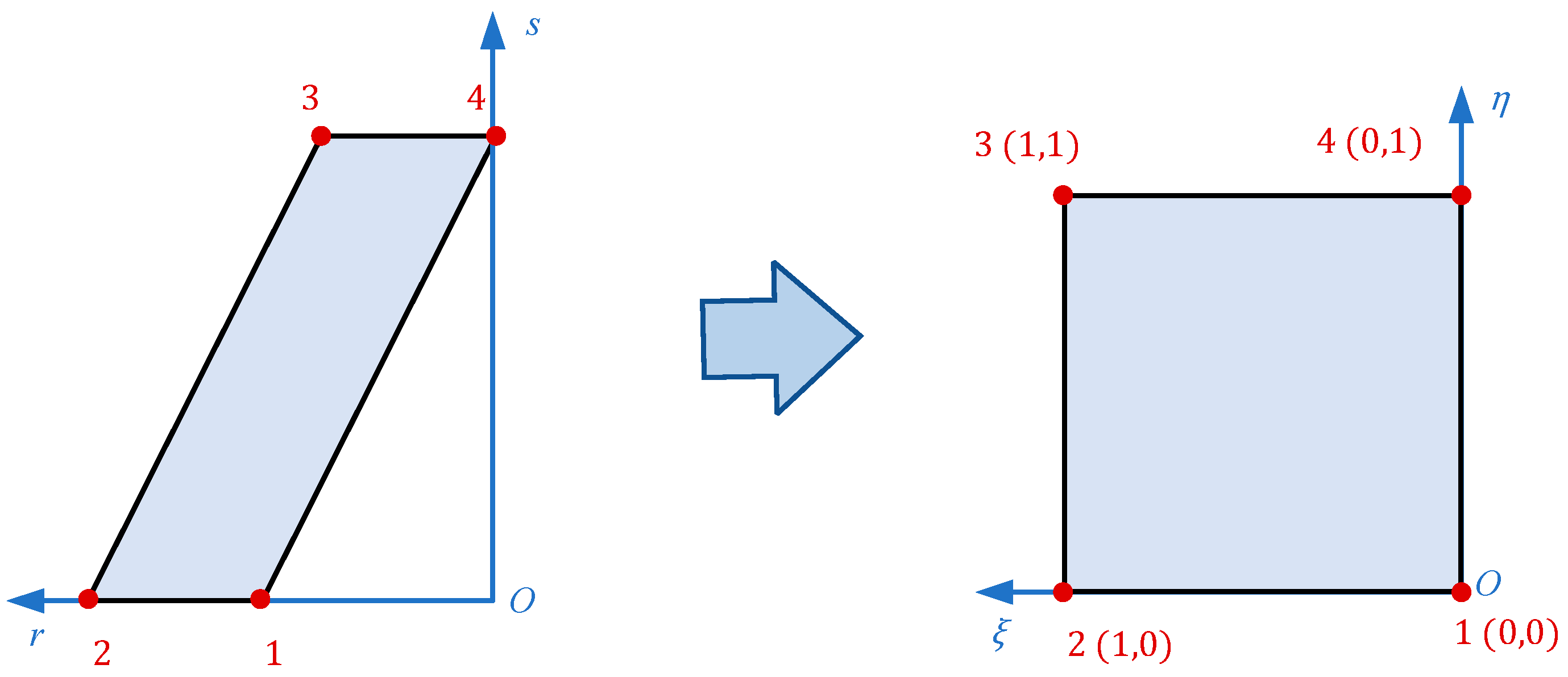
In order to facilitate the establishment of a unified model of rotational cavity coupling systems, it is necessary to transform the parallelogram cross-sections in the system into square cross-sections. As illustrated in Figure 2, coordinate transformations are used to transform the plane ros coordinate system into the plane ξoη coordinate system. The expressions for the coordinate transformation equations and shape functions are given by Equations (1) and (2).
r s = i = 1 4 N i ξ , η r i s i
N i ξ , η = 1 i + 1 1 ξ i ξ 1 η i η
(r(i), s(i)) represent the coordinates of the i-th vertex in the ros plane coordinate system, and Ni (ξ, η) denotes the shape function of the i-th vertex on the plane. Meanwhile, (ξ(i), η(i)) signifies the coordinates of the i-th vertex in the ξoη plane coordinate system (i = 1, 2, 3, 4).
The transformation relations for the coordinates can be written in matrix form:
ξ η T = J r s T
J = r ξ s ξ r η s η
r ξ = i = 1 4 N i ξ , η r i ξ r η = i = 1 4 N i ξ , η r i η s ξ = i = 1 4 N i ξ , η s i ξ s η = i = 1 4 N i ξ , η s i η
The inverse form of Equation (3) can also be written as follows:
r s T = J 1 ξ η T
J 1 = J 11 J 12 J 21 J 22 = 1 J s η s ξ r η r ξ
Table 1 provides the relevant parameters for the conversion between the 0cylinder-cylinder cavity, spherical-cylinder cavity, and cone-cylinder cavity coupling systems: (1) the relationship between the local coordinate system and the double-curvature coordinate system of the cavity unit in each cavity coupling system, (2) the Lame coefficients for rotational cavities, (3) the maximum values for each coordinate axis in the system, and (5) the coordinate transformation parameters.
The model of the coupled system is shown in Figure 3, and its cross-sectional geometric parameters and coordinate systems are as follows:
(a) The coupling system consisting of a composite laminated rotationally stiffened plate and cylindrical-cylindrical double-cavity configuration includes two local systems of coordination: (o-s, θ, r) and (on- zn, θn, xn). The composite laminated rotationally stiffened plate and the two cylindrical acoustic cavities share the same inner radius and outer radius, denoted as R1 and R2, respectively. The difference between them is given by R = R1R2. The thickness of the laminated plate is hp, and the curvature radius of the laminated beams is Rbn, with a width of bn and a thickness of hn. The thickness of the acoustic cavities is H, and their heights are denoted as L1 and L2, respectively. The rotation angle of the entire coupling systems is ϑ. (b) The coupling system consists of the composite laminated rotationally stiffened plate [15] and the spherical-cylindrical double-cavity configuration includes three local systems of coordination (o-φ1, θ1, r1), (o-s2, θ2, r2), and (on-zn, θn, xn). R1 and R2 represent the inner and outer radii of the composite laminated rotationally stiffened plate and the two cavities, respectively. The laminated plate has a thickness of hp, and the curvature radius of the laminate beams is Rbn with a width of bn and a thickness of hn. The thickness of the cavities is denoted as H. The apex angle of spherical cavity 1 is ϕ = ϕ2ϕ1, and L corresponds to the height of cylindrical cavity 2. (c) The coupling system between the composite laminated rotationally stiffened plate and the conical-cylindrical double-cavity configuration includes two local systems of coordination (o-s, θ, r) and (on- zn, θn, xn). The conical cavity 1 has small- and large-end radii R1 and R2, with a cone apex angle α and a generatrix length L1. The inner and outer radii of the composite laminated rotationally stiffened plate and the two cavities are denoted as R2 and R3, respectively. The laminated plate has a thickness of hp, and the curvature radius of the laminated beams is Rbn, with a width of bn and a thickness of hn. The height of the cylindrical cavity is L2, and the overall thickness of the coupled system cavities is H. To research the displacement and acoustic response characteristics of the coupled system, a single sound source Q and a harmonic point force F, which can be placed at any position within the coupled system, have been added.
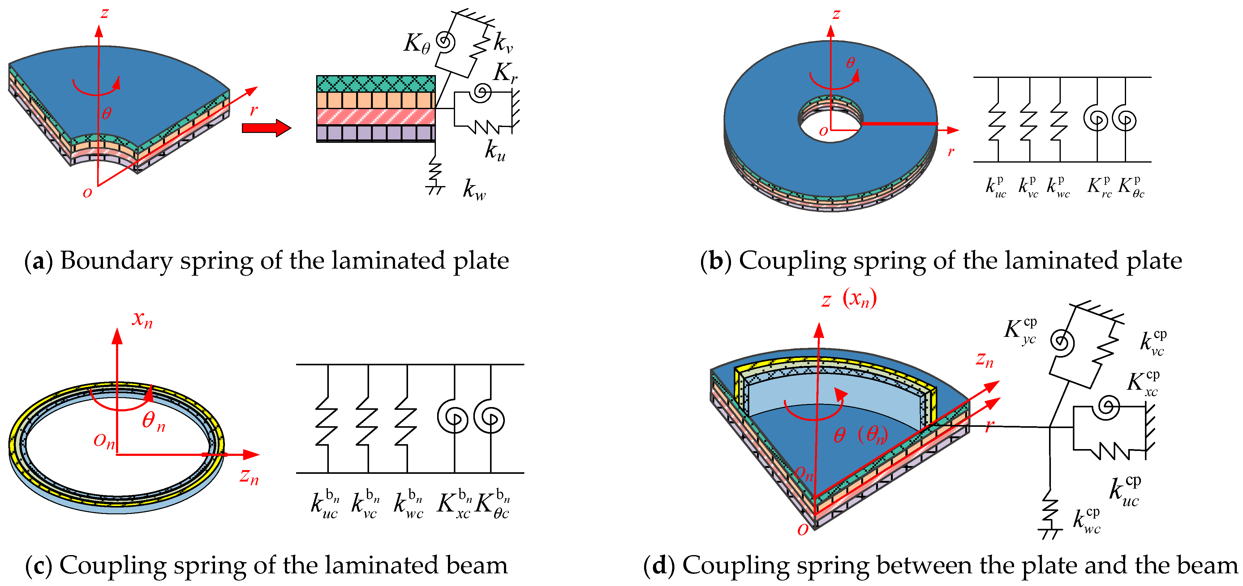
According to the artificial virtual spring technology [16,17,18], as shown in Figure 4a, for the edge of the laminated, rotationally stiffened plate, the general boundary conditions can be expressed by inserting three sets of linear springs ku, kv, and kw along the u, v, and w directions and two sets of torsional springs, Kr and Kθ. These spring groups are consistently distributed along the boundary. k θ 0 u , k θ 0 v , k θ 0 w , K θ 0 r , and K θ 0 θ represent five sets of spring of the boundary at the θ = 0° boundary [19]; similarly, the spring of the boundary at θ = ϑ, r = 0, and r = Rp can be represented using this approach. For the sector-shaped composite stiffened plate, the spring of the boundary at r = 0 has a stiffness of 0. For the ring-shaped composite stiffened plate, the boundary springs at θ = 0° and θ = 360° have a stiffness of 0. For the circular composite stiffened plate, the boundary springs at r = 0, θ = 0°, and θ = 360° all have a stiffness value of 0. When the angle of rotation ϑ = 360°, the composite laminated plate (the nth laminated beam) in the composite laminated rotationally stiffened plate will generate the coupled boundary, as shown in Figure 4 b, c. This coupling is achieved by uniformly setting three sets of linear coupling springs k u c p , k v c p , and k w c p ( k u c b n , k v c b n , k w c b n ), and two sets of torsional coupling springs, K r c p , K θ c p , and ( K x c b n , K θ c b n ) on the coupled boundary. Figure 4d represents the coupling springs uniformly set between the laminated plate and the laminated beams in the composite laminated rotationally stiffened plate, including three sets of linear coupling springs k u c cp , k v c cp , and k w c cp and two sets of torsional coupling springs, K x c cp and K y c cp .

2.2. Construction of Allowable Displacement and Sound Pressure Functions

According to the FSDT and the two-dimensional modified Fourier series expression, the allowable displacement functions [20,21] of the composite laminated rotationally stiffened plate are formulated. the allowable functions of the sound pressure of two cylindrical cavities are established by using the three-dimensional modified Fourier series expression. The specific expressions of the allowable displacement and sound pressure functions are as follows [22,23]:
u p ( r , θ , t ) = e j ω t Φ u M r , θ + N q = 1 2 Φ u N q r , θ A m n v p ( r , θ , t ) = e j ω t Φ v M r , θ + N q = 1 2 Φ v N q r , θ B m n w p ( r , θ , t ) = e j ω t Φ w M r , θ + N q = 1 2 Φ w N q r , θ C m n ϕ r p ( r , θ , t ) = e j ω t Φ ϕ r M r , θ + N q = 1 2 Φ ϕ r N q r , θ D m n ϕ θ p ( r , θ , t ) = e j ω t Φ ϕ θ M r , θ + N q = 1 2 Φ ϕ θ N q r , θ E m n
u b n ( θ n , t ) = e j ω t Ψ u n Ω θ n + Θ q = 1 2 Ψ u n Θ q θ n A l v b n ( θ n , t ) = e j ω t Ψ v n Ω θ n + Θ q = 1 2 Ψ v n Θ q θ n B l w b n ( θ n , t ) = e j ω t Ψ w n Ω θ n + Θ q = 1 2 Ψ w n Θ q θ n C l ϕ x b n ( θ n , t ) = e j ω t Ψ ϕ r n Ω θ n + Θ q = 1 2 Ψ ϕ r n Θ q θ n D l ϕ θ b n ( θ n , t ) = e j ω t Ψ ϕ θ n Ω θ n + Θ q = 1 2 Ψ ϕ θ n Θ q θ n E l
p 1 r 1 , θ 1 , s 1 , t = e j ω t P 1 Ω r 1 , θ 1 , s 1 + Θ q = 1 6 P 1 Θ q ( r 1 , θ 1 , s 1 ) A m t n t l t p 2 r 2 , θ 2 , s 2 , t = e j ω t P 2 Ω r 2 , θ 2 , s 2 + Θ q = 1 6 P 2 Θ q ( r 2 , θ 2 , s 2 ) B m t n t l t
The detail expressions are given in Appendix A. The supplementary polynomial of the displacement of the composite laminated plate [15] could be represented as ΦM and ΦNq (Nq = 1, 2). These parameters can be expressed as:
Φ u M = Φ w M = Φ v M = Φ ϕ r M = Φ ϕ θ M = cos λ 0 α r cos λ 0 β θ , , cos λ m α r cos λ n β θ , , cos λ 0 α r cos λ N b θ , , cos λ M α r cos λ N β θ Φ u N 1 = Φ v N 1 = Φ w N 1 = Φ ϕ r N 1 = Φ ϕ θ N 1 = sin ( λ 2 α r ) cos ( λ 0 β θ ) , , sin ( λ 2 α r ) cos ( λ n β θ ) , , sin ( λ 2 α r ) cos ( λ N β θ ) , , sin ( λ 1 α r ) cos ( λ N β θ ) Φ u N 2 = Φ v N 2 = Φ w N 2 = Φ ϕ r N 2 = Φ ϕ θ N 2 = cos ( λ 0 α r ) sin ( λ 2 β θ ) , cos ( λ 0 α r ) sin ( λ 1 β θ ) , , cos ( λ m α r ) sin ( λ 2 β θ ) , , cos ( λ M α r ) sin ( λ 1 β θ )
The displacement supplement polynomial of the nth laminated beam could be expressed as ΨnΩ and ΨnΘqq = 1, 2). These parameters can be expressed as:
Ψ u n Ω = Ψ v n Ω = Ψ w n Ω = Ψ ϕ x n Ω = Ψ ϕ θ n Ω = cos λ 0 α n θ n , , cos λ l α n θ n , cos λ L α n θ n Ψ u n Θ 1 = Ψ v n Θ 1 = Ψ w n Θ 1 = Ψ ϕ x n Θ 1 = Ψ ϕ θ n Θ 1 = α n 2 π sin π θ n 2 α n + α n 2 π sin 3 π θ n 2 α n Ψ u n Θ 2 = Ψ v n Θ 2 = Ψ w n Θ 2 = Ψ ϕ x n Θ 2 = Ψ ϕ θ n Θ 2 = α n 2 π cos π θ n 2 α n + α n 2 π cos 3 π θ n 2 α n
The pressure supplement polynomial of the nth cavity can be expressed as PnΩ and PnΘq (Θq = 1, 2, …, 6): these parameters can be expressed as:
P n Ω r n , θ n , s n = cos λ 0 α n r n cos λ 0 β n θ n cos λ 0 z n s n , , cos λ 0 α n r n cos λ 0 β n θ n cos λ L c z n s n , , cos λ 0 α n r n cos λ N c β n θ n cos λ L c z n s n , , cos λ M c α n r n cos λ N c β n θ n cos λ L c z n s n P n Θ 1 ( r n , θ n , s n ) = sin λ 2 α n r n cos λ 0 β n θ n cos λ 0 z n s n , , sin λ 2 α n r n cos λ 0 β n θ n cos λ L c z n s n , , sin λ 2 α n r n cos λ N c β n θ n cos λ L c z n s n , , sin λ 1 α n r n cos λ N c β n θ n cos λ L c z n s n P n Θ 2 ( r n , θ n , s n ) = cos λ 0 α n r n sin λ 2 β n θ n cos λ 0 z n s n , , cos λ 0 α n r n sin λ 2 β n θ n cos λ L c z n s n , , cos λ 0 α n r n sin λ 2 β n θ n cos λ L c z n s n , , cos λ M c α n r n sin λ 1 β n θ n cos λ L c z n s n P n Θ 3 ( r n , θ n , s n ) = cos λ 0 α n r n cos λ 0 β n θ n sin λ 2 z n s n , cos λ 0 α n r n cos λ 0 β n θ n sin λ 1 z n s n , , cos λ 0 α n r n cos λ N c β n θ n sin λ 2 z n s n , , cos λ M c α n r n cos λ N c β n θ n sin λ 1 z n s n P n Θ 4 ( r n , θ n , s n ) = sin λ 2 α n r n sin λ 2 β n θ n cos λ 0 z n s n , , sin λ 2 α n r n sin λ 2 β n θ n cos λ L c z n s n , , sin λ 2 α n r n cos λ 1 β n θ n cos λ L c z n s n , , sin λ 1 α n r n cos λ 1 β n θ n cos λ L c z n s n P n Θ 5 ( r n , θ n , s n ) = sin λ 2 α n r n cos λ 0 β n θ n sin λ 2 z n s n , sin λ 2 α n r n cos λ 0 β n θ n sin λ 1 z n s n , , sin λ 2 α n r n cos λ N c β n θ n sin λ 2 z n s n , , sin λ 1 α n r n cos λ N c β n θ n sin λ 1 z n s n P n Θ 6 ( r n , θ n , s n ) = cos λ 0 α n r n sin λ 2 β n θ n sin λ 2 z n s n , cos λ 0 α n r n sin λ 2 β n θ n cos λ 1 z n s n , , cos λ 0 α n r n sin λ 1 β n θ n sin λ 2 z n s n , , cos λ M c α n r n sin λ 1 β n θ n cos λ 1 z n s n
where λ m α = m π / α , λ n β = n π / β , λ m t α n = m t π / α n , λ l α n = l π / α n , λ n t α n = n t π / α n , λ l t α n = l t π / α n (n = 1, 2).

2.3. Stress-Strain and Displacement Relations

According to the relevant knowledge of elastic mechanics, normal and shear strain at any location on the composite, laminated plate [24] or the laminated beam can be defined in terms of mid-surface strains and curvature changes:
ε r p = ε r p 0 + z χ r p ε θ p = ε θ p 0 + z χ θ p
γ r θ p = γ r θ p 0 + z χ r θ p γ r z p = γ r z p 0 γ θ z p = γ θ z p 0 ε θ b n = ε θ b n 0 + z χ θ b n γ θ x b n = γ θ x b n 0 + z χ θ x b n γ θ z b n = γ θ z b n 0 γ x z b n = γ x z b n 0
The detail expressions are given in Appendix A. Hooke’s law may be used to determine the stress-strain relationship between the laminated plate and the laminated curved beam at the k-th layer:
σ r p σ θ p τ r θ p τ r z p τ θ z p = Q 11 k ¯ Q 12 k ¯ 0 0 Q 16 k ¯ Q 21 k ¯ Q 22 k ¯ 0 0 Q 26 k ¯ 0 0 Q 44 k ¯ Q 45 k ¯ 0 0 0 Q 54 k ¯ Q 55 k ¯ 0 Q 61 k ¯ Q 62 k ¯ 0 0 Q 66 k ¯ ε r p ε θ p γ r θ p γ r z p γ θ z p
σ θ b n τ θ x b n τ θ z b n τ x z b n = Q 22 k ¯ 0 0 Q 26 k ¯ 0 Q 44 k ¯ Q 45 k ¯ 0 0 Q 54 k ¯ Q 55 k ¯ 0 Q 62 k ¯ 0 0 Q 66 k ¯ ε θ b n γ θ x b n γ θ z b n γ x z b n
where Q i j k ¯ (i, j = 1, 2, …, 6) is the relevant stiffness coefficient, which can be obtained from the following equation:
Q 11 k ¯ Q 12 k ¯ 0 0 Q 16 k ¯ Q 21 k ¯ Q 22 k ¯ 0 0 Q 26 k ¯ 0 0 Q 44 k ¯ Q 45 k ¯ 0 0 0 Q 54 k ¯ Q 55 k ¯ 0 Q 61 k ¯ Q 62 k ¯ 0 0 Q 66 k ¯ = T Q 11 k Q 12 k 0 0 0 Q 21 k Q 22 k 0 0 0 0 0 Q 44 k 0 0 0 0 0 Q 55 k 0 0 0 0 0 Q 66 k T T
In Equation (16), T is the transformation matrix, defined as follows; the included angle between the main direction and the r direction is called θk and is the layer angle:
T = cos 2 θ k sin 2 θ k 0 0 2 sin θ k cos θ k sin 2 θ k cos 2 θ k 0 0 2 sin θ k cos θ k 0 0 cos θ k sin θ k 0 0 0 sin θ k cos θ k 0 sin θ k cos θ k sin θ k cos θ k 0 0 cos 2 θ k sin 2 θ k
in which Q i j k represents the k layer’s material coefficient of the k layer of the laminated plate (laminated curved beam), the value of which may be achieved using the engineering constant of the k layer of the laminated plate (laminated curved beam):
Q 11 k = E 1 1 μ 12 μ 21   Q 12 k = μ 12 E 2 1 μ 12 μ 21 = Q 21 k   Q 22 k = E 2 1 μ 12 μ 21 Q 44 k = G 23   Q 55 k = G 13   Q 66 k = G 12
where E1 and E2 are Young’s modulus; G12, G13, and G23 are the shear moduli. According to the symmetry of the flexible matrix, the engineering constants of the orthotropic materials satisfy the following equations. The relationship between Poisson’s ratio μ12 and μ21 is as follows: μ12E2 = μ21E1.
Integrating the stresses on the plane yields the forces and moments experienced by the laminated plate and the laminated curved beam. From one layer of the laminated plate and laminated curved beam to the other layer, by integrating the thickness, we can obtain:
N r p N θ p N r θ p M r p M θ p M r θ p = A 11 A 12 A 16 B 11 B 12 B 16 A 12 A 22 A 26 B 12 B 22 B 26 A 16 A 26 A 66 B 16 B 26 B 66 B 11 B 12 B 16 D 11 D 12 D 16 B 12 B 22 B 26 D 12 D 22 D 26 B 16 B 26 B 66 D 16 D 26 D 66 ε r p 0 ε θ p 0 γ r θ p 0 χ r p χ θ p χ r θ p
Q θ p Q r p = κ s ¯ A 44 A 45 A 45 A 55 γ θ z p 0 γ r z p 0
N θ b n N θ x b n M θ b n M θ x b n = A 22 A 26 B 22 B 26 A 26 A 66 B 26 B 66 B 22 B 26 D 22 D 26 B 26 B 66 D 26 D 66 ε θ b n 0 γ θ x b n 0 χ θ b n χ θ x b n
Q x b n Q θ b n = κ s ¯ A 44 A 45 A 45 A 55 γ x z b n 0 γ θ z b n 0
A i j = k = 1 N L Q i j k ¯ Z k + 1 Z k   B i j = 1 2 k = 1 N L Q i j k ¯ Z k + 1 2 Z k 2 D i j = 1 3 k = 1 N L Q i j k ¯ Z k + 1 3 Z k 3
In which N r p , N θ p , and N r θ p represent the resultant force in the plane of the laminated plate; M r p , M θ p , and M r θ p represent the bending and torsional moments in the plane of the laminated plate; and Q θ p and Q r p are the resultant force of the horizontal shear force of the laminated plate. N θ b n and N θ x b n represent the resultant force in the plane of the laminated curved beam, M θ b n and M θ x b n represent the bending and torsional moments in the plane of the laminated curved beam, and Q x b n and Q θ b n are the resultant force of the horizontal shear force in the plane of the laminated curved beam. κ s ¯ is the shear correction coefficient, N L indicates the layer number of the laminated plate or laminated curved beam, Zk is the thickness coordinate value of the bottom surface of the k layer, and Zk+1 is the thickness coordinate value of the upper surface.

2.4. Energy Functional

The energy equation of the coupled system of composite laminated rotationally stiffened plate and acoustic cavities can be derived, with the expression of the Lagrangian equation of the coupled system, as follows:
L P = T P U P U P - coupling U S P W P & B n W P & C 1 W P & C 2 + W F
L B n = T B n U B n U B n - coupling W P & B n
L C 1 = T C 1 U C 1 U C 1 - coupling W P & C 1 + W C 1 - wall + W Q 1
L C 2 = T C 2 U C 2 - U C 2 - coupling W P & C 2 + W C 2 wall + W Q 2
where T P , T B n , T C n and, respectively, represent the entire kinetic energy of the composite, laminated plate, the nth laminated beam, and the nth cavity. U P , U B n , and U C n represent the entire potential energy of the laminated plate, the nth laminated beam, and the nth cavity, respectively. U P - coupling , U B n - coupling , and U C n - coupling denote the coupling potential energy of the laminated plate, the nth laminated beam, and the nth cavity when ϑ = 360. U S P represents the potential energy due to the boundary springs of the laminated plate. W P & B n is the coupling potential energy between the laminated plate and the nth laminated beam; W P & C 1 and W P & C 2 represent the coupling potential energy between the laminated plate and cavity 1 and cavity 2, respectively. W C n - wall indicates the impedance potential energy generated by the impedance wall surface within the nth cavity. W F indicates the work performed by the harmonic point force F on the composite laminated rotationally stiffened plate. W Q n indicates the work performed by the monopole-point sound source within the coupling system’s nth cavity.
Several total kinetic energies within the coupled system T P , T B n , and T C n can be written as:
T P = 1 2 0 R p 0 ϑ I p 0 u p t 2 + 2 I p 1 u p t ϕ r p t + I p 2 ϕ r p t 2 + I p 0 v p t 2 + 2 I p 1 v p t ϕ θ p t + I p 2 ϕ θ p t 2 + I p 0 w p t 2 r + R 1 d r d θ
I p 0 = k = 1 N L Z k Z k + 1 ρ p k d z I p 1 = k = 1 N L Z k Z k + 1 ρ p k z d z I p 2 = k = 1 N L Z k Z k + 1 ρ p k z 2 d z
T B n = 1 2 0 ϑ I b n 0 u b n t 2 + 2 I b n 1 u b n t ϕ x b n t + I b n 2 ϕ x b n t 2 + I b n 0 v b n t 2 + 2 I b n 1 v b n t ϕ θ b n t + I b n 2 ϕ θ b n t 2 + I b n 0 w b n t 22 R b n d θ n
I b n 0 = k = 1 N L Z k Z k + 1 ρ b n k d z n I b n 1 = k = 1 N L Z k Z k + 1 ρ b n k z n d z n I b n 2 = k = 1 N L Z k Z k + 1 ρ b n k z n 2 d z n
T C n = 1 2 ρ C n ω 2 0 L α n 0 L β n 0 L z n J 11 n 2 + J 21 n 2 p n Ω H z n z n + q = 1 6 p n Θ q H z n z n 2 + J 11 n J 21 n p n Ω H z n z n + q = 1 6 p n Θ q H z n z n p n Ω H α n α n + q = 1 6 p n Θ q H α n α n + J 12 n 2 + J 22 n 2 p n Ω H α n α n + q = 1 6 p n Θ q H α n α n 2 + J 12 n J 22 n p n Ω H z n z n + q = 1 6 p n Θ q H z n z n p n Ω H α n α n + q = 1 6 p n Θ q H α n α n + p n Ω H β n β n + q = 1 6 p n Θ q H β n β n 2 J n H α n H β n H z n d α n d β n d z n
Several total potential energies within the coupled system Up, UBn and UCn can be written as:
U P = U stretch + U s - b + U bend = 1 2 0 R p 0 ϑ N r p ε r p 0 + N r p ε r p 0 + N r θ p γ r θ p 0 + M r p χ r p + M θ p χ θ p + M r θ p χ r θ p + Q r p γ r z p 0 + Q θ p γ θ z p 0 r d r d θ
U B n = 1 2 0 ϑ A 22 v b n R b n θ + w b n R b n 2 + 2 A 26 u b n R b n θ v b n R b n θ + w b n R b n + A 66 u b n R b n θ 2 + κ s ¯ A 44 ϕ x b n 2 + 2 κ s ¯ A 45 w b n R b n θ v b n R b n + ϕ θ b n ϕ x b n + κ s ¯ A 55 w b n R b n θ v b n R b n + ϕ θ b n 2 + 2 B 22 ϕ θ b n R b n θ v b n R b n θ + w b n R b n + 2 B 26 ϕ x b n R b n θ v b n R b n θ + w b n R b n + 2 B 26 ϕ θ b n R b n θ u b n R b n θ + 2 B 66 ϕ x b n R b n θ u b n R b n θ + D 22 ϕ θ b n R b n θ 2 + D 66 ϕ x b n R b n θ 2 + 2 D 26 ϕ x b n R b n θ ϕ θ b n R b n θ R b n d θ n
U C n = 1 2 ρ C n c n 2 0 L α n 0 L β n 0 L z n P n Ω α n , β n , z n + q = 1 6 P n Θ q α n , β n , z n 2 J n H α n H β n H z n d α n d β n d z n
ρ p k represents the material density of the kth layer of the laminated plate, ρ b n k represents the material density of the kth layer of the laminated beam, ρ C n represents the density of the acoustic medium inside cavity n, c n represents the speed at which acoustic waves propagate within cavity n, and ω represents the circular frequency of the rotationally acoustic cavity.
When ϑ = 360°, the potential energy of coupling within the coupled system U P - coupling , the coupled potential energy of the nth laminated curved beam U B n - coupling , and the coupled potential energy of the nth sound cavity U C n - coupling can be written as:
U P - coupling = 1 2 0 R p h p / 2 h p / 2 k u c p u p θ = 360 u p θ = 0 2 + k v c p v p θ = 360 v p θ = 0 2 + k w c p w p θ = 360 w p θ = 0 2 + K r c p ϕ r p θ = 360 ϕ r p θ = 0 2 + K θ c p ϕ θ p θ = 360 ϕ θ p θ = 0 2 d z d r
U B n - coupling = 1 2 0 ϑ h n / 2 h n / 2 k u c b n u b n θ n = 360 u b n θ n = 0 2 + k v c b n v b n θ n = 360 v b n θ n = 0 2 + k w c b n w b n θ n = 360 w b n θ n = 0 2 + K x c b n ϕ x b n θ n = 360 ϕ x b n θ n = 0 2 + K θ c b n ϕ θ b n θ n = 360 ϕ θ b n θ n = 0 2 d z n
U C n - coupling = 0 L α n 0 L z n P n Ω α n , 0 , z n H β n β n + q = 1 6 P n Θ q α n , 0 , z n H β n β n P n Ω α n , 0 , z n + q = 1 6 P n Θ q α n , 0 , z n P n Ω α n , L β n , z n + q = 1 6 P n Θ q α n , L β n , z n J n H α n H z n d α n d z n
The specific expression of the potential energy of the boundary spring U S P is:
U S P = U S P θ + U S P s
U S P θ = 1 2 0 ϑ h p / 2 h p / 2 k r 0 u u p 2 + k r 0 v v p 2 + k r 0 w w p 2 + K r 0 r ϕ r p 2 + K r 0 θ ϕ θ p 2 r = 0 + k r R p u u p 2 + k r R p v v p 2 + k r R p w w p 2 + K r R p r ϕ r p 2 + K r R p θ ϕ θ p 2 r = R p r + R 1 d z d θ
U S P s = 1 2 0 R p h p / 2 h p / 2 k θ 0 u u p 2 + k θ 0 v v p 2 + k θ 0 w w p 2 + K θ 0 r ϕ r p 2 + K θ 0 θ ϕ θ p 2 θ = 0 + k θ ϑ u u p 2 + k θ ϑ v v p 2 + k θ ϑ w w p 2 + K θ ϑ r ϕ r p 2 + K θ ϑ θ ϕ θ p 2 θ = ϑ d z d r
The potential energy of coupling generated when the laminated plate and the nth laminated curved beam W P & B n are coupled can be expressed as:
W P & B n = 1 2 0 ϑ k u c cp u p r = R b w b n 2 + k v c cp v p r = R b v b n 2 + k w c cp w p r = R b u b n 2 + K x c cp ϕ r p r = R b ϕ x b n 2 + K y c cp ϕ θ p r = R b ϕ θ b n 2 d θ
The specific expressions of W P & C 1 and W P & C 2 , which indicate the potential energy of coupling between the laminated plate and cavity 1 and cavity 2, respectively, are as follows:
W P & C 1 = 0 R p 0 ϑ Φ M + N q = 1 2 Φ N q P 2 Ω + Θ q = 1 6 P 2 Θ q s = h c 1 A m n F m t n t l t + Φ M + N q = 1 2 Φ N q P 2 Ω + Θ q = 1 6 P 2 Θ q s = L 1 B m n A m t n t l t + Φ M + N q = 1 2 Φ N q P 2 Ω + Θ q = 1 6 P 2 Θ q s = L 1 C m n A m t n t l t + h p 2 Φ M + N q = 1 2 Φ N q P 2 Ω + Θ q = 1 6 P 2 Θ q s = L 1 D m n A m t n t l t + h p 2 Φ M + N q = 1 2 Φ N q P 2 Ω + Θ q = 1 6 P 2 Θ q s = L 1 E m n A m t n t l t r 1 + R 1 d r 1 d θ 1
W P & C 2 = 0 R p 0 ϑ Φ M + N q = 1 2 Φ N q P 2 Ω + Θ q = 1 6 P 2 Θ q s = 0 A m n G m t n t l t + Φ M + N q = 1 2 Φ N q P 2 Ω + Θ q = 1 6 P 2 Θ q s = 0 B m n B m t n t l t + Φ M + N q = 1 2 Φ N q P 2 Ω + Θ q = 1 6 P 2 Θ q s = 0 C m n B m t n t l t + h p 2 Φ M + N q = 1 2 Φ N q P 2 Ω + Θ q = 1 6 P 2 Θ q s = 0 D m n B m t n t l t + h p 2 Φ M + N q = 1 2 Φ N q P 2 Ω + Θ q = 1 6 P 2 Θ q s = 0 E m n B m t n t l t r 2 + R 1 d r 2 d θ 2
As an example, for 0 < ϑ < 2π, the dissipated energy due to the impedance wall surface within cavity n in the coupled system can be expressed as:
W C n - wall = 1 2 j ω S r i = 1 6 P n Ω α n , β n , z n + q = 1 6 P n Θ q α n , β n , z n 2 Z r d S r
W C n - wall = W C n - wall 1 + W C n - wall 2 + W C n - wall 3 + W C n - wall 4 + W C n - wall 5 + W C n - wall 6
in which j represents the imaginary unit. Sr indicates the region of the r-th surface of uncoupled acoustic wall, where Zr is the equivalent acoustic wall impedance.
The work performed by the harmonic point force F on the laminated plate within the composite stiffened plate is expressed as follows:
W F = S f u u p + f v v p + f w w p + f ϕ r ϕ r p + f ϕ θ ϕ θ p r d r d θ
f i = F δ ( r r 0 ) δ ( θ θ 0 )
where fi (i = uj, vj, wj, ϕr, ϕθ) are functions of the outside load distribution; the location of the harmonic point force F is at (r0, θ0).
The work performed by the source of point sound within cavity n in the coupled system W Q n can be expressed as:
W Q n = 1 j ω 0 L α n 0 L β n 0 L z n P n Ω α n , β n , z n + q = 1 6 P n Θ q α n , β n , z n Q s n J n H α n H β n H z n d α n d β n d z n
Q s n = 4 π A j ρ C n c n k δ c α α e δ c β β e δ c z z e
in Equation (52), Q s n is the point sound source’s distribution function acting within cavity n. The amplitude of the source of the point sound is denoted as A (kg/s2); its related location of action is (αe, βe, ze). δc represents the three-dimensional Dirac delta function. The wavenumber of sound is represented by k, which is the ratio of circular frequency ω to the speed of sound cn: k = ω/cn.
Once the energy equation of the coupling system has been obtained, it can be solved using the Rayleigh-Ritz method [25,26]:
L P P m n = T P P m n U P P m n U P - coupling P m n U S P P m n W P & B n P m n W P & C 1 P m n W P & C 2 P m n + W F P m n = 0
L B n Q l = T B n Q l U B n Q l U B n - coupling Q l W P & B n Q l = 0
L C 1 A m t n t l t = T C 1 A m t n t l t U C 1 A m t n t l t U C 1 - coupling A m t n t l t W P & C 1 A m t n t l t + W C 1 - wall A m t n t l t + W Q 1 A m t n t l t = 0
L C 2 B m t n t l t = T C 2 B m t n t l t U C 2 B m t n t l t U C 2 - coupling B m t n t l t W P & C 2 B m t n t l t + W C 2 - wall B m t n t l t + W Q 2 B m t n t l t = 0
P m n = A m n B m n C m n D m n E m n T
Q l = A l B l C l D l E l T
where Pmn represents the two-dimensional unknown Fourier coefficient matrix of the laminated plate, and Ql represents the one-dimensional unknown Fourier coefficient matrix of the laminated beam.
For an acoustic cavity with an impedance wall, its characteristic values are generally complex, forming a complex modal problem, which, in physics, represents the system undergoing damped oscillations. In the complex characteristic values, the real part corresponds to the natural circular frequency of the acoustic cavity, and the imaginary part represents modal decay. Furthermore, the imaginary part is a relatively small number. Therefore, in this study of natural frequencies, only the structure-acoustic coupling system under a rigid wall is considered. Equations (53)–(58) can be transformed into matrix form:
( K P ω 2 M P ) P m n + C B n & P Q l + C C 1 & P A m t n t l t C C 2 & P B m t n t l t = F
( K B n ω 2 M B n ) Q l + C P & B n P m n = 0
( K c 1 ω Z c 1 ω 2 M c 1 ) A m t n t l t + ω 2 C P & C 1 P m n = Q 1
( K c 2 ω Z c 2 ω 2 M c 2 ) B m t n t l t ω 2 C P & C 2 P m n = Q 2
where K P , K B n and K c n indicate the laminated plate’s stiffness matrices, the nth laminated beam, and the nth acoustic cavity, respectively. M P , M B n , and M c n are the laminated plate’s mass matrices, the nth laminated beam, and the nth acoustic cavity, respectively. C B n & P denotes the coupling matrix between the nth laminated beam and the laminated plate, C P & B n = C B n & P T , while Z c n is the matrix of impedance of the nth cylindrical cavity. C C n & P represents the acoustic-structural coupling matrix within the laminated plate and the nth cylindrical acoustic cavity, while C P & C n = C C n & P T .
When Fn and Qn are set to 0, meaning that no point force or point sound source are introduced, the system of equations for solving the natural frequencies and mode shapes of the coupled system between the composite laminated rotationally stiffened plate and acoustic cavities can be obtained. Eventually, the natural frequencies ω and their corresponding modes G of the coupled system can be determined. By substituting the source of the point sound and the harmonic point force into Equations (63)–(65), the steady-state response of the coupling system could be acquired. The detail expressions are given in Appendix A.
R ω S G = 0
R = K P C P & B C P & C 1 C P & C 2 C B & P K B 0 0 0 0 K C 1 0 0 0 0 K C 2
S = M P 0 0 0 0 M B 0 0 C C 1 & P 0 M C 1 0 C C 2 & P 0 0 M C 2

3. Numerical Results and Discussion

Following to the developed, unified analytical model of the vibro-acoustic properties of the coupling system between the composite laminated rotationally stiffened plate and the acoustic cavities, numerical discussions and results analyses were conducted in this section to further study its vibro-acoustic coupling characteristics [27]. This part primarily validated the convergence and accuracy of the coupling system model, investigated the factors that influence the natural frequencies of free vibration, and investigated the steady-state response analysis of the coupling system while being affected by the source of point sound and point force. The materials utilized for the laminated plate and laminated beams are listed in Table 2. The acoustic cavities in the coupled system are primarily modeled using air as the acoustic medium, with air density defined as ρair = 1.21 kg/m3. The speed of sound in air is specified as cair = 340 m/s.

3.1. Verification of Convergence and Correctness

Here, we validate the convergence and accuracy of the previously established model of the coupled system of the composite laminated rotationally stiffened plate and acoustic cavities. The convergence of the coupled system primarily depends on the truncation values of the composite laminated rotationally stiffened plate (Mp, Np) and the cavities (Mc, Nc, Qc). Table 3 provides the natural frequencies of the coupling system among the composite laminated rotationally stiffened plate and cylindrical-cylindrical cavities under various plate and cavity truncation conditions obtained using the present method. These results are compared with finite element simulation results [28].
The boundaries of the composite laminated rotationally stiffened plate are set to SSSS, the number of stiffeners (n) is 1, and the coupling system’s geometric parameters are as follows: R1 = 0.4 m, R2 = 1.2 m, L1 = 0.5 m, L2 = 1 m, hp = 0.02 m, ϑ = 90°, Rb1 = 0.8 m, b1 = 0.06 m, and h1 = 0.04 m. The material of the laminated plate is graphite epoxy resin with a layer angle of [0°/90°], the material of the laminated beams is Q235 steel, and the medium in the cavities is air.
From Table 3, it is evident that when Mc × Nc × Qc is 3 × 3 × 3 and Mp × Np is 18 × 18, the natural frequencies of various modes have essentially converged. Compared with finite element simulation results, the maximum error in the natural frequencies of all modes is less than 2.12%. The size and coordinate system used in the finite element model are the same as that of the model established in this paper, the mesh size is 0.02 of the global size, and the element shape of the sound cavity is the AC3D20:20 node-acoustic quadric hexahedron element. The shape of the composite structural element is C3D20R, the twenty-node hexahedron element.
The natural frequencies of the coupling system among the composite laminated rotationally stiffened plate and the cylindrical-spherical cavities under different plate truncation values and cavity truncation conditions obtained using the present method and the finite element method are shown in Table 4. In this case, the boundaries of the composite laminated rotationally stiffened plate are scheduled to SSSS, the number of stiffeners (n) is 1, and the coupling system’s geometric parameters are as follows: R1 = 0.4 m, R2 = 1.2 m, ϕ1 = 30°, ϕ2 = 90°, L = 1.5 m, hp = 0.02 m, ϑ = 90°, Rb1 = 0.8 m, b1 = 0.06 m, and h1 = 0.04 m. The material of the laminated plate, laminated beams, layer angles, and the medium in the cavities are the same as in Table 3.
Similarly, from Table 4, it can be observed that the natural frequencies of various modes have essentially converged when Mc × Nc × Qc is 4 × 4 × 4 and Mp × Np is 18 × 18. At this point, the maximum error in the natural frequencies of all modes compared to the finite element method results is 1.83%.
Table 5 presents the natural frequencies of the coupling system among the composite laminated rotationally stiffened plate and the cylindrical-conical cavities under different plate truncation values and cavity truncation conditions obtained using the present method and the finite element method. The boundaries of the composite laminated rotationally stiffened plate are set to SSSS, the number of stiffeners (n) is 1, and the coupling system’s geometric parameters are as follows: R1 = 0.6 m, R2 = 1.2 m, R3 = 1.8 m, α = 30°, L = 2 m, hp = 0.02 m, ϑ = 90°, Rb1 = 1.5 m, b1 = 0.06 m, and h1 = 0.04 m. The material of the laminated plate, laminated beams, layer angles, and the medium in the cavities remain the same as in Table 3 and Table 4.
It can be observed that the natural frequencies of various modes have essentially converged when Mc × Nc × Qc is 4 × 4 × 4 and Mp × Np is 18 × 18. At this point, the maximum error in the natural frequencies of all modes as compared to the finite element method results is less than 3.51%. A continuous function can be expanded by Fourier series, where the truncation value is the Fourier coefficient, which characterizes the smoothness and convergence of the function. According to the Fourier series convergence property and theorem, when the truncation value goes to infinity, the Fourier coefficient goes to zero. However, in numerical calculation, the truncation value needs to be set as a finite number of terms; in order to ensure the correctness of the calculation results, the truncation value of the Fourier series in the displacement or sound pressure function needs to be increased until the solution results are stable. Therefore, the numerical calculation in Table 2, Table 3 and Table 4 is carried out here with the aim of finding a more reasonable combination of truncation values for the following examples. In order to fully satisfy the convergence and accuracy, Mc×Nc×Qc = 4 × 4 × 4 and Mp × Np = 18 × 18 are selected as the cutoff values in the following numerical examples.
Next, we will research the stiffness values of the springs in the coupled system, which specifically include linear springs k(ku, kv, kw), torsional springs K(Kr, Kθ), and plate-beam coupling springs kcp ( k u c cp , k v c cp , k w c cp , K x c cp , and K y c cp ). Due to the influence of acoustic cavity coupling in the coupled system, we will not analyze the in-plate coupling springs kc ( k u c p , k v c p , k w c p , K r c p , K θ c p ) here.
Taking the example of the coupling system among the composite, laminated, rotational plate and the cylindrical-spherical cavities, we will analyze the impact of the boundary-spring stiffness values. Figure 5 provides the variation curves of the first four natural frequencies under different boundary-spring stiffness values. The material parameters and the dimensional parameters of the coupled system are the same as those in Table 4.
As shown in Figure 5a, initially, the torsional spring stiffness value K is set to zero, and when the linear boundary spring stiffness value k varies in the range from 10−4 to 105, the natural frequencies of the coupled system remain at zero. At this point, the laminated plate is considered to have free boundary conditions. As the linear spring stiffness value increases, the natural frequencies of the coupled system also increase. When the linear spring stiffness value k increases to 1012, the natural frequencies become relatively stable, and the boundaries of the laminated plate in the coupling system can be considered as simply supported.
In Figure 5b, the linear boundary spring stiffness value is kept constant at 1016. Because the laminated plate in the coupled system is located between two cavities, the displacement in the torsional direction is already restricted. Therefore, the natural frequencies of the coupled system remain unchanged as the torsional spring stiffness value K increases. It can be assumed that the natural frequencies of the laminated plate in the coupled system remain consistent when the boundary conditions are either clamped or simply supported. Table 6 provides the values of the boundary spring stiffness under different boundary conditions and also lists the values of two elastic boundary condition spring stiffness values besides the classical boundary conditions.
Similarly, we research the plate-beam coupling conditions, taking the example of the coupling system among the composite laminated rotationally stiffened plate and the cylindrical-cylindrical cavities. In this case, the material parameters and dimensional parameters are the same as those in Table 3. Figure 6 provides the variation curves of the natural frequencies under different plate-beam coupling spring stiffness values for two boundary conditions. From Figure 6, it can be observed that, when the plate-beam coupling spring stiffness value kcp is less than 104, the natural frequencies remain stable and are smaller than when the stiffness value kc is relatively large. In this range, the plate-beam coupling springs have little effect on the natural frequencies of the coupled system. However, when the stiffness value kcp increases to 1011, it becomes possible to achieve rigid coupling at the boundary between the composite laminated rotationally stiffened plate and the laminated beam in the coupled system.
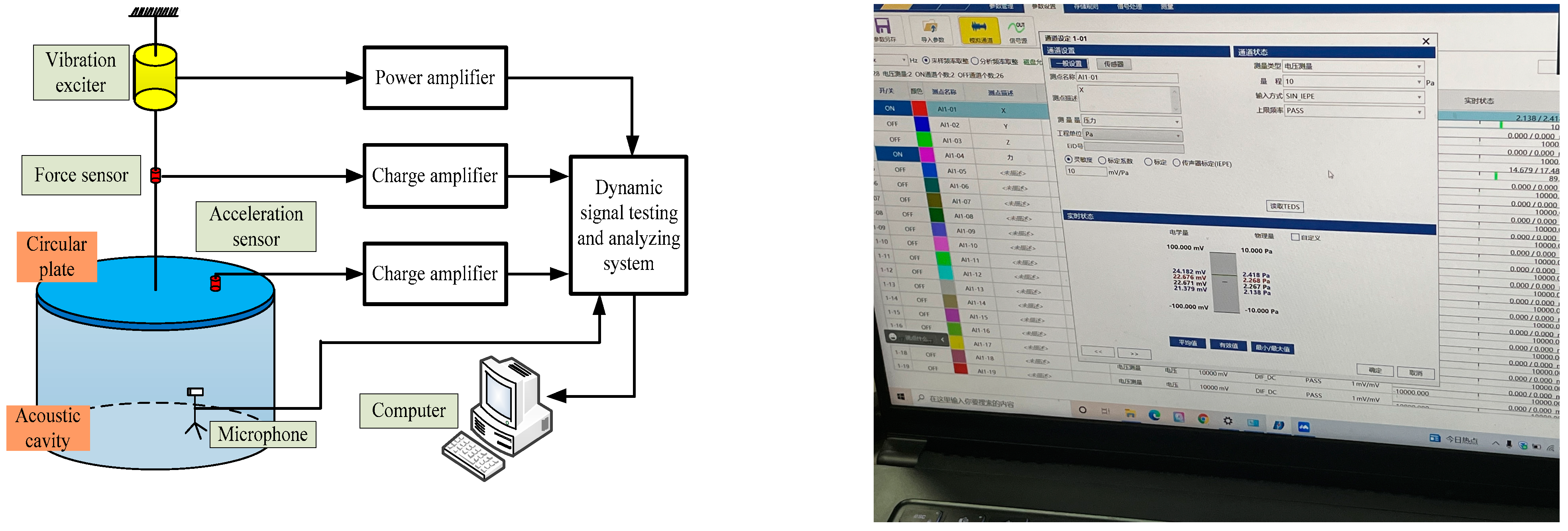
This study conducted experiments using a coupled system between a circular stiffened plate and a cylindrical cavity, which is relatively straightforward to implement, to validate the correctness of the unified analysis model of the vibro-acoustic characteristics of the coupled system between a composite laminated rotationally stiffened plate and acoustic cavities presented in this paper. The experimental setup included an LC02 impact hammer, a 3A105 force sensor, a DH5857-1 charge amplifier, a 1A116E accelerometer sensor, and a DH5922D dynamic signal testing and analysis system, as well as a C-35 Bluetooth speaker, an MPA201 loudspeaker, a DH40200 shaker, and a YE5872A power amplifier. The experiment was conducted in an acoustic chamber to minimize the influence of external environmental noise on the test results. Data were collected by opening the Bluetooth speaker to provide a point source excitation for the cylindrical-cylindrical cavity system. A JZK-20 shaker was secured above the circular stiffened plate and connected to the YE5872A power amplifier. The DH5922D dynamic signal testing and analysis system was also connected to the power amplifier for control of the shaker. Data collection commenced after setting the point force amplitude and phase within the system. The amplitude and phase of the point force could be adjusted using the knobs on the power amplifier. After collecting specific frequency sound pressure values under point force and ambient noise excitations, the two sets of values were subtracted.
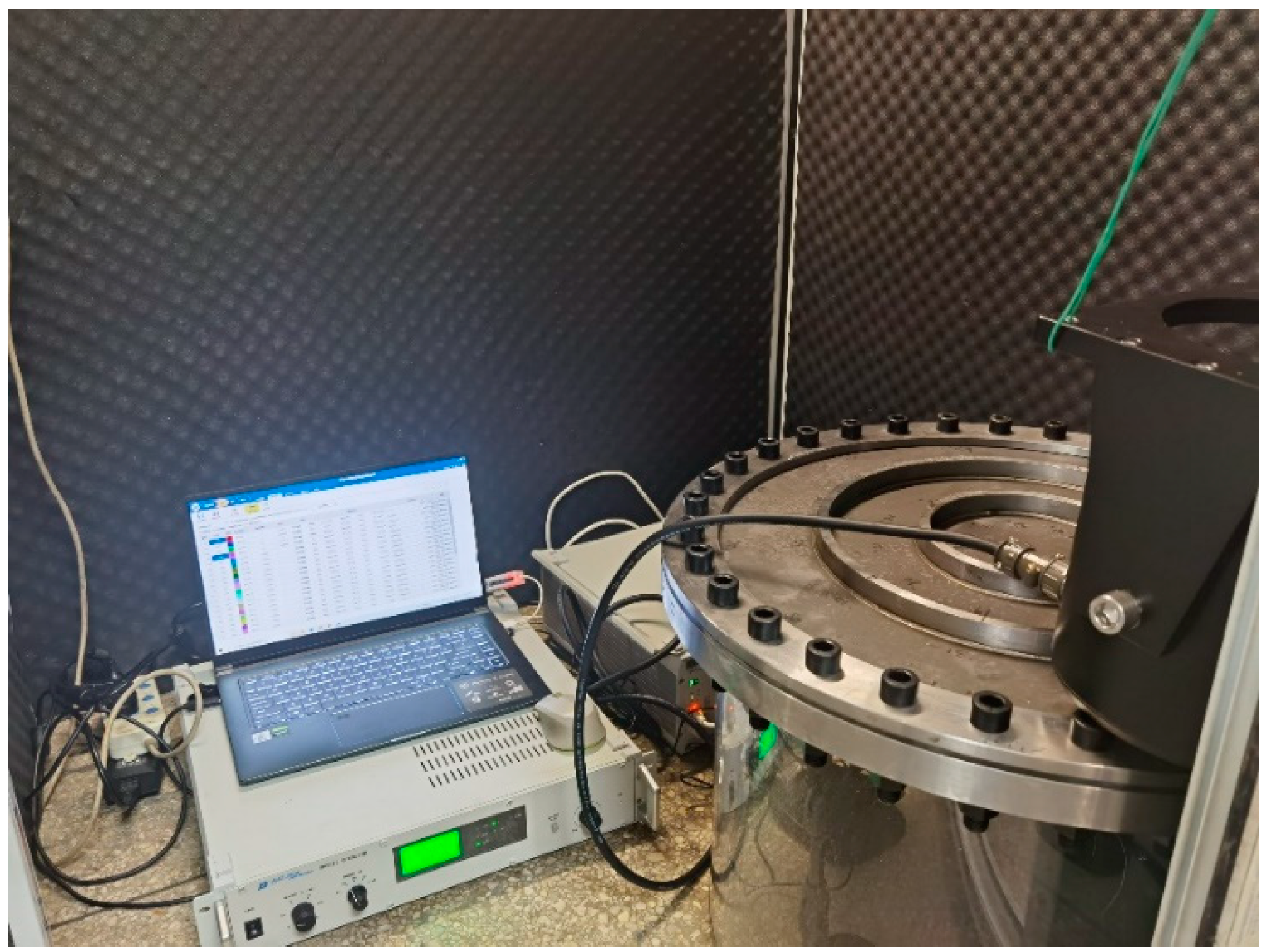
The coupled system between the circular stiffened plate and the cylindrical cavity consisted of a clamped Q235 steel circular stiffened plate and an acrylic cylindrical cavity. The circular plate was connected with top and bottom plates using 32 evenly spaced Φ16 bolts to create a clamped boundary condition. The structural dimensions of the stiffened circular plate used in the experiment are as follows: R1 = 0 m, R2 = 0.265 m, hp = 0.005 m, Rb1 = 0.088 m, Rb2 = 0.177 m, b1 = b2 = 0.02 m, h1 = h2 = 0.01 m, and ϑ = 360°. The circular plate was made of either Q235 steel or carbon fiber composite material. The material parameters of Q235 steel are: E = 216 GPa, μ = 0.3, and ρp = 7800 kg/m3. The material parameters of the carbon fiber composite material are: E1 = E2 = 77.8 GPa, G1 = G2 = G3 = 77.8 GPa, μ = 0.26, and ρp = 7800 kg/m3. The layer angle of the composite material is [0°/90°/0°/90°/0°]. The main body of the cylindrical-cylindrical cavity coupling system was constructed from a 10 mm thick transparent acrylic plate and comprises a cylindrical shell and two circular plates. The effective dimensions of the cavity coupling system are as follows: R1 = 0 m, R2 = 0.265 m, L = 0.4 m, and ϑ = 360°. Additionally, a 20 mm diameter hole was opened at an appropriate position on the cylindrical shell to cross the wires of various test instruments.
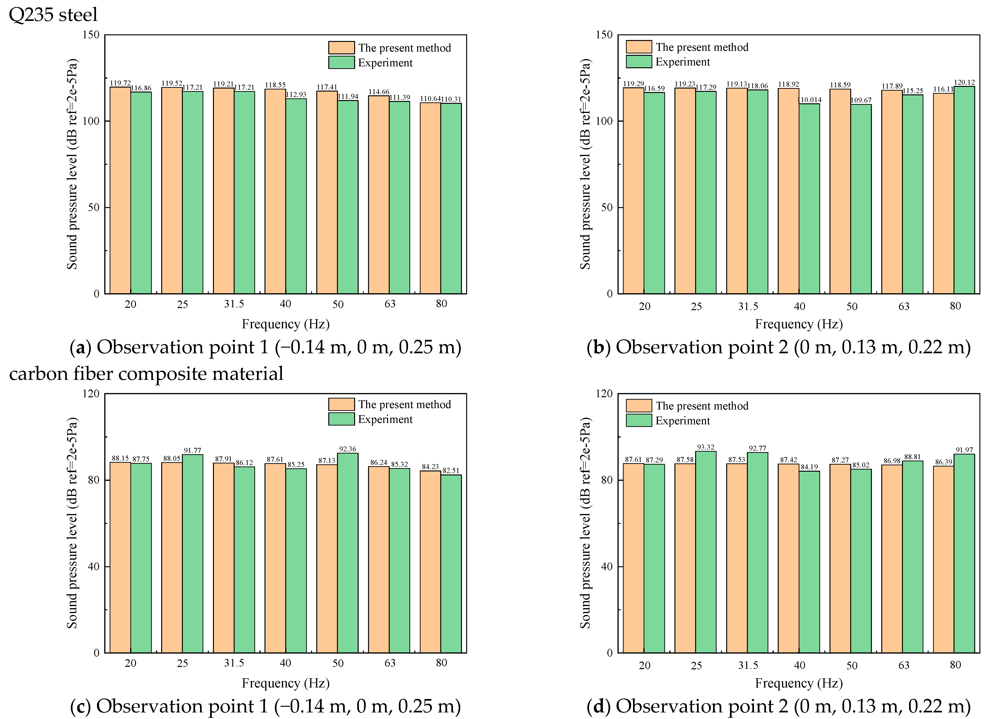
Figure 7 presents the test schematic diagram of the coupled system between the circular stiffened plate, the cylindrical cavity, and the software parameter interface. The arrangement of the coupled system between the circular stiffened plate, the cylindrical cavity, and the experimental instruments in the sound pressure response test is shown in Figure 8. Figure 9 presents the sound pressure comparison between the experimental measurements and the results obtained using the present method of the coupled system between the circular stiffened plate and the cylindrical cavity at specific frequencies and at different observation points. The observation points are located at (0.14 m, 0.14 m) on the circular stiffened plate: observation point 1 is located at (−0.14 m, 0 m, 0.25 m) inside the cylindrical cavity, and observation point 2 is located at (0 m, 0.13 m, 0.22 m) inside the cylindrical cavity. From Figure 9, it can be observed that the maximum error among the experimental measurements and the results calculated using the present method is within an acceptable range of 7.49%, demonstrating the correctness of the unified analysis model of the vibro-acoustic characteristics of the coupled system established in this study.

3.2. Free Vibration Analysis

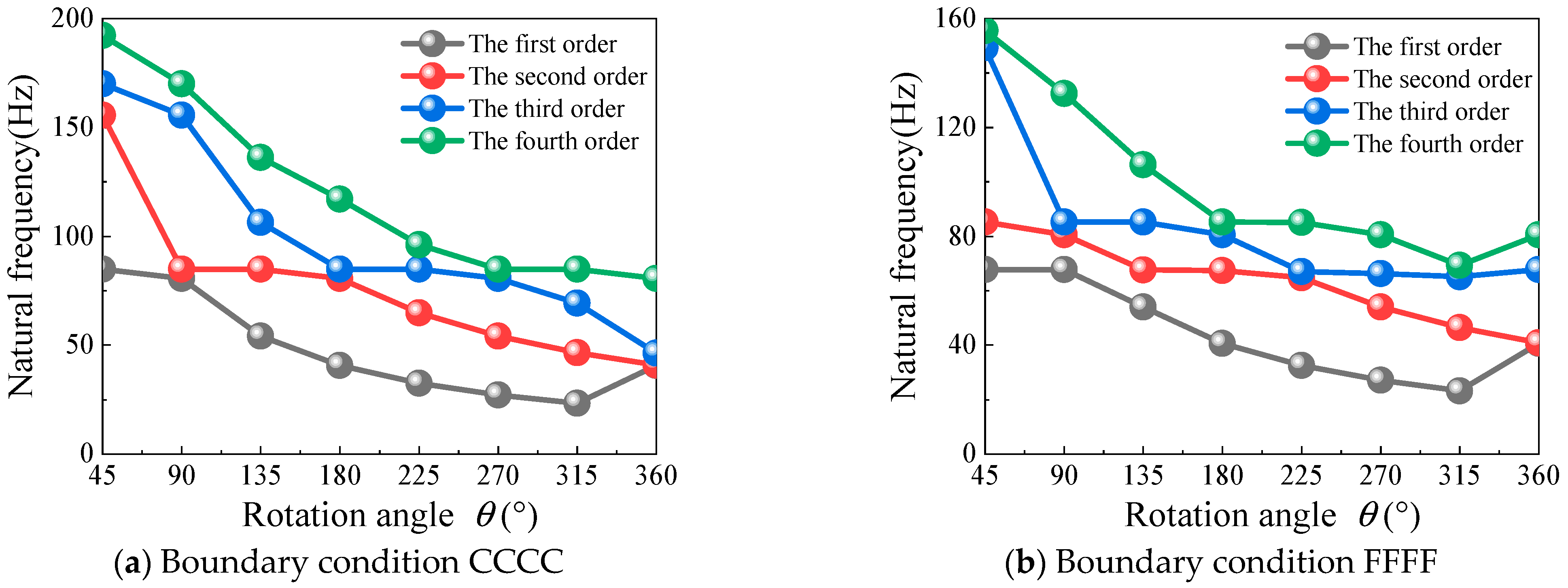
This part focuses on the free vibration of the coupled system between the composite laminated rotationally stiffened plate and the cylindrical-cylindrical, spherical-cylindrical, and conical-cylindrical cavities, studying the impact of relevant factors affecting the coupled system’s vibro-acoustic characteristics. Figure 10 depicts the variation curve of the coupled system’s natural frequencies between the composite laminated rotationally stiffened plate and the cylindrical-cylindrical cavity at different rotation angles. In this case, the number of stiffeners in the composite laminated rotationally stiffened plate is n = 2. The geometric parameters determined of the coupling system are: R1 = 0.9 m, R2 = 1.8 m, L1 = 1 m, L2 = 2 m, hp = 0.03 m, Rb1 = 1.2 m, b1 = 0.08 m, h1 = 0.06 m, Rb2 = 1.5 m, b2 = 0.08 m, and h2 = 0.06 m. The material of the laminated plate and stiffeners is glass epoxy resin, with a layer angle of [90°/0°/90°], and the medium in the cavities is air. The boundary conditions are defined as CCCC.
As shown in Figure 10, the natural frequencies of the coupled system decrease as the rotation angle ϑ increases, but this trend changes when the rotation angle ϑ = 360° is reached. Table 7 provides the first eight natural frequencies of the coupled system at different rotation angles. It can be observed that the natural frequencies at ϑ = 360° are roughly the same as those at ϑ = 180°. In the case of coupling between two sound walls, a closed loop is formed, resulting in repeated modes and causing an increase in the natural frequencies of all orders. These conditions explain the reason for the increase in natural frequencies at ϑ = 360°, as shown in Figure 10.
Table 8 and Table 9 present the coupling system’s initial eight natural frequencies among the composite laminated rotationally stiffened plate, the spherical-cylindrical cavities, and the conical-cylindrical cavities for different inner-to-outer radius ratios and rotation angles. In this example, the number of stiffeners in the composite laminated rotationally stiffened plate is n = 2; the calculated geometric parameters are as follows:
(a) Spherical-Cylindrical: R1 = 0.9 m, R2 = 1.8 m, ϕ1 = 30°, ϕ2 = 90°, L = 2 m, hp = 0.03 m, Rb1 = 1.2 m, b1 = 0.08 m, h1 = 0.06 m, Rb2 = 1.5 m, b2 = 0.08 m, and h2 = 0.06 m.
(b) Conical-Cylindrical: R1 = 0.6 m, R2 = 1.2 m, R3 = 1.8 m, α = 30°, H = 0.6 m, L2 = 2 m, hp = 0.03 m, Rb1 = 1.4 m, b1 = 0.08 m, h1 = 0.06 m, Rb2 = 1.6 m, b2 = 0.08 m, and h2 = 0.06 m.
The material of the laminated plate and stiffeners is glass epoxy resin, with a layer angle of [90°/0°/90°], and the medium in the cavities is air. The numerical results in Table 8 and Table 9 show that the influence of the rotation angle on the vibro-acoustic characteristics is applicable to both the coupled system between the composite laminated rotationally stiffened plate and the spherical-cylindrical and conical-cylindrical cavities, similar to the coupling system among the composite laminated rotationally stiffened plate and the cylindrical-cylindrical cavity.
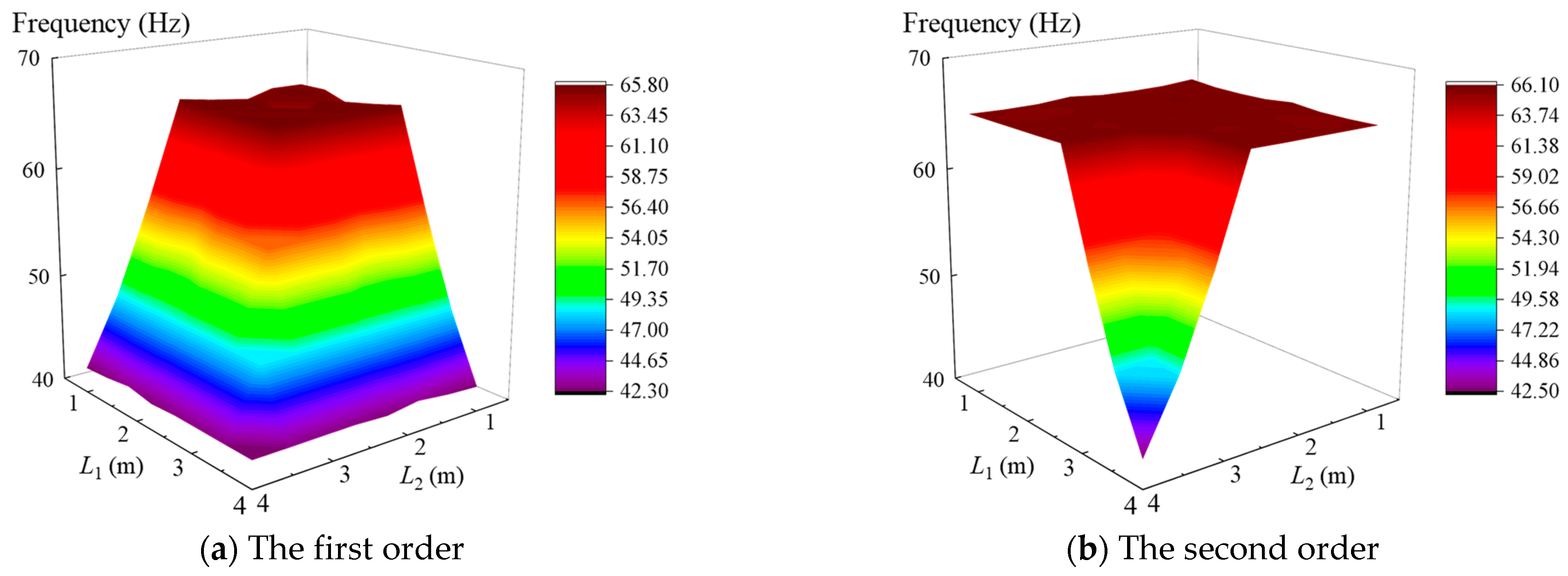
For the coupling system between the composite laminated rotationally stiffened plate and the cylindrical-cylindrical cavities, it is necessary to analyze the influence of the heights L1 and L2 of cylindrical cavities 1 and 2 on the natural frequencies of the coupled system. Figure 11 shows the trends of the first four natural frequencies of the coupled system as L1 and L2 vary. In this example, the number of stiffeners is n = 2, and the calculated parameters of geometry are as follows: R1 = 0.8 m, R2 = 1.7 m, ϑ = 120°, hp = 0.02 m, Rb1 = 1.1 m, b1 = 0.05 m, h1 = 0.05 m, Rb2 = 1.4 m, b2 = 0.05 m, and h2 = 0.05 m. The material of the laminated plate and stiffeners is graphite epoxy resin, with a layer angle of [90°/0°/90°], and the medium in the cavities is air. The boundary conditions are set as CCCC. From Figure 8, it is evident that the natural frequencies of the coupled system at the same order decrease as the heights L1 and L2 of cylindrical cavities 1 and 2 increase.
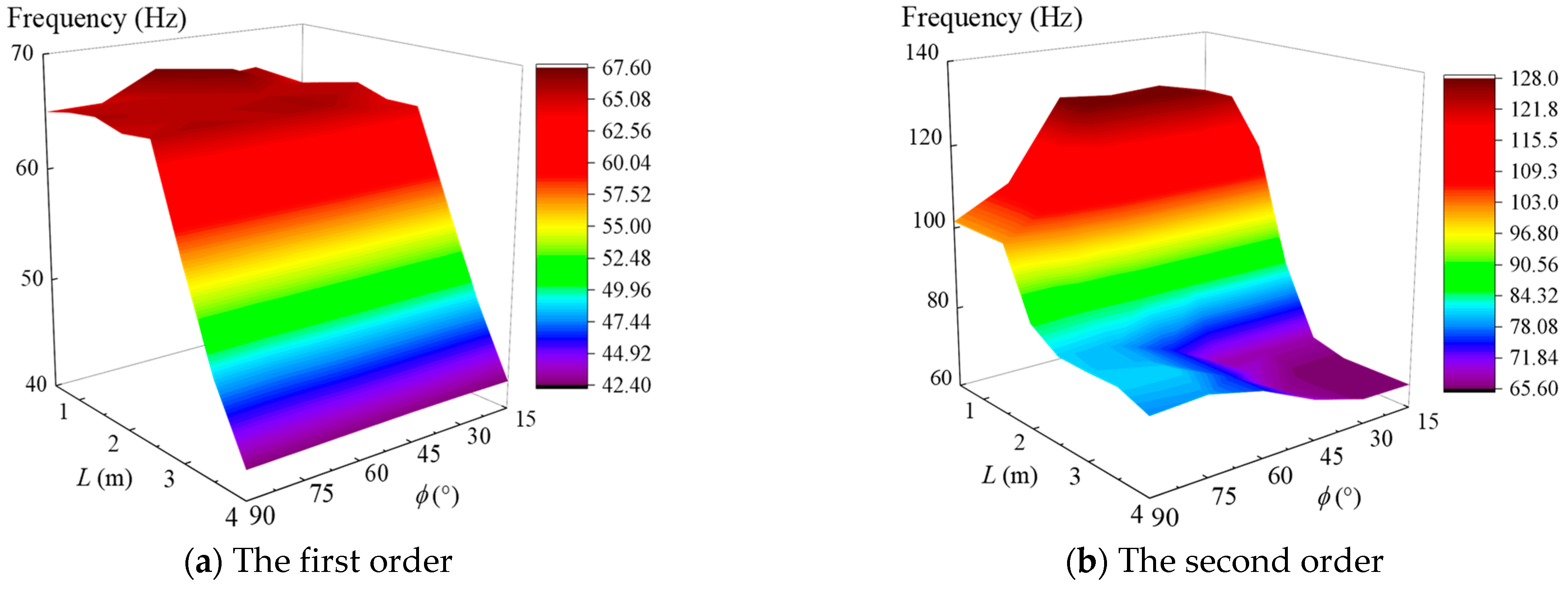
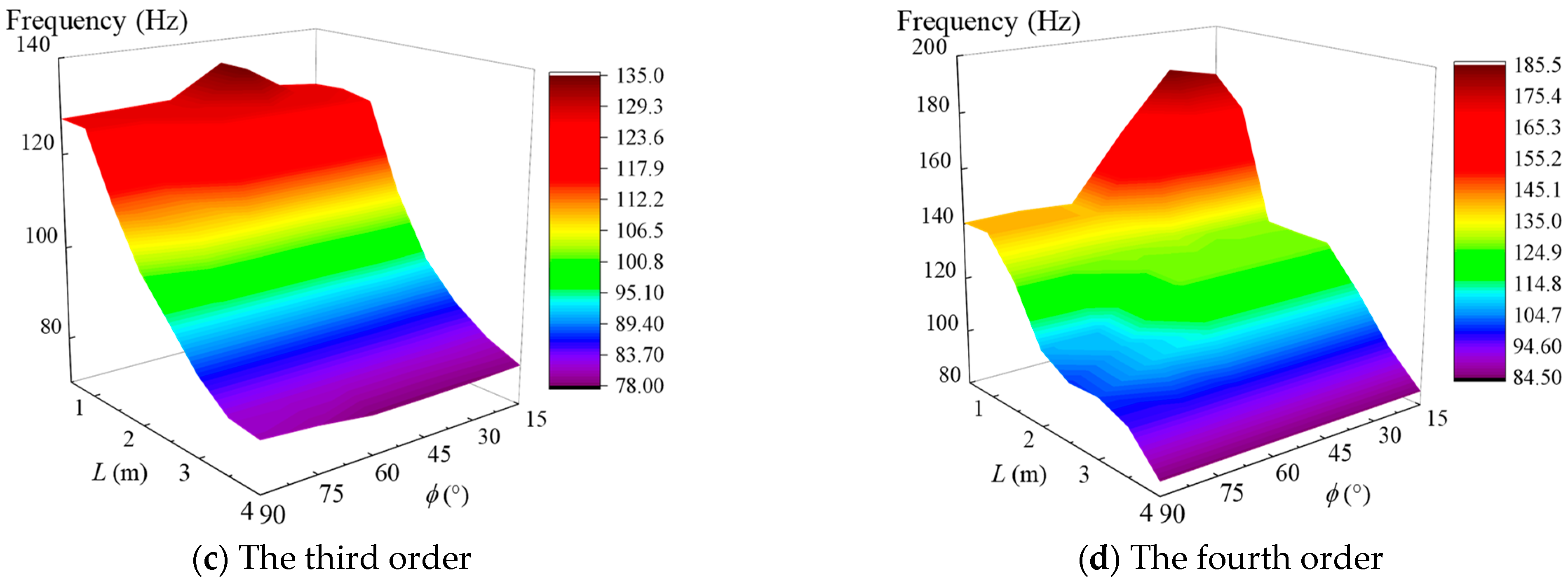
The parametric study of the coupling system among the composite laminated rotationally stiffened plate and the spherical-cylindrical cavity considers both the height L of the cylindrical cavity and the top angle ϕ of the spherical cavity. Figure 12 illustrates the trends of the first four natural frequencies of the coupled system between the composite laminated rotationally stiffened plate and the spherical-cylindrical cavity as ϕ and L vary. In this example, the number of stiffeners is n = 2, the calculated parameters of geometry are as follows: R1 = 0.8 m, R2 = 1.7 m, ϑ = 120°, ϕ2 = 90°, hp = 0.02 m, Rb1 = 1.1 m, b1 = 0.05 m, h1 = 0.05 m, Rb2 = 1.4 m, b2 = 0.05 m, and h2 = 0.05 m.
The material used is graphite epoxy resin with a layer angle of [90°/0°/90°], and the medium in the cavities is air. The boundary conditions are set as CCCC. As shown in Figure 12, the natural frequencies of the coupled system in the same order decrease as the height L of the cylindrical cavity increases. The top angle ϕ of the spherical cavity also generally causes a decrease in the system’s natural frequencies, but the effect within the range of 0° to 90° is relatively small.
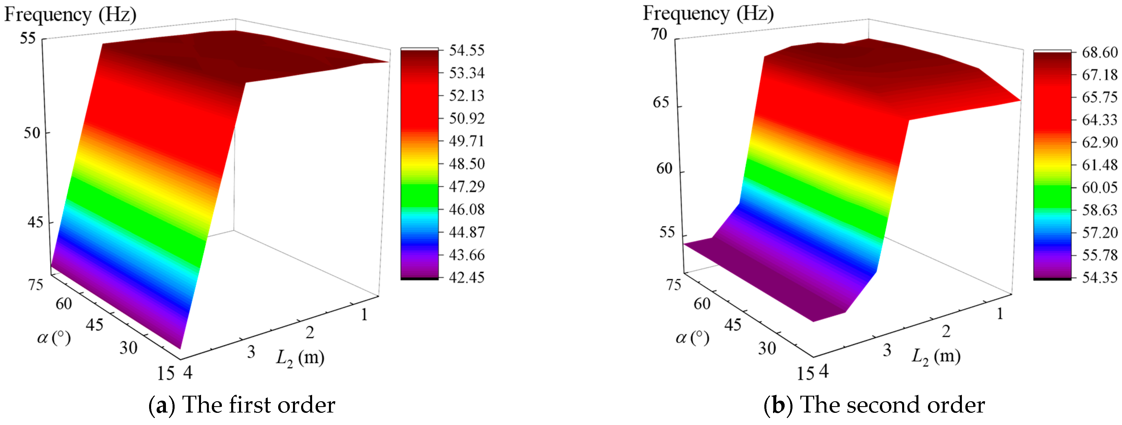
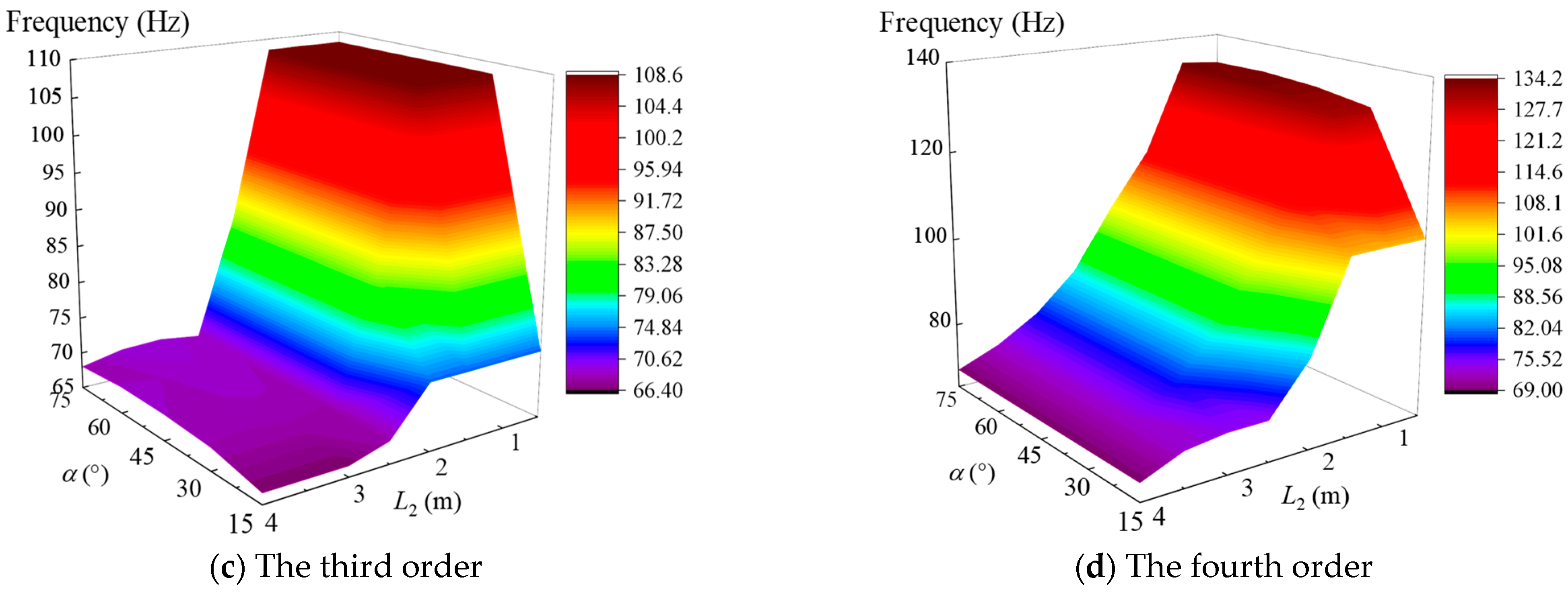
We consider the influence of the cone top angle α of the conical cavity and the height L2 of the cylindrical cavity on the natural frequency of the coupled system between the composite laminated rotationally stiffened plate and the conical-cylindrical cavity, and the parametric analysis is carried out. Figure 13 illustrates the trend surface plots of the first four natural frequencies of the coupled system as α and L2 vary. In this example, the number of stiffeners is n = 2, and the determined geometric parameters are as follows: R1 = 0.6 m, R2 = 1.3 m, R3 = 1.9 m, H = 0.4 m, ϑ = 120°, hp = 0.02 m, Rb1 = 1.5 m, b1 = 0.05 m, h1 = 0.05 m, Rb2 = 1.7 m, b2 = 0.05 m, and h2 = 0.05 m.
The material used is graphite epoxy resin with a layer angle of [90°/0°/90°], and the medium in the cavities is air. The boundary conditions are set as CCCC. From Figure 13, it can be observed that the natural frequencies of the coupled system at the same order decrease as the height L2 of the cylindrical cavity increases, and the frequencies increase with the increase of the cone top angle α of the conical cavity.
Compared to the rotationally acoustic cavity coupling system, the coupled system between the composite laminated rotationally stiffened plate and the acoustic cavity is also influenced by the essential parameters for the composite stiffened plate. Therefore, it needs to be parametrically studied. The coupling system’s initial eight natural frequencies under different boundaries are shown in Table 10. In this example, the geometric parameters of the coupling system are the same as those in Table 7, Table 8 and Table 9, with a rotation angle of ϑ = 180°. The material used is isotropic steel.
From Table 10, it can be observed that the natural frequencies of the three coupling systems rise as the stiffness values of the boundary springs increase, and the findings for elastic boundary 1 (E1) and elastic boundary 2 (E2) support this conclusion.

3.3. Steady-State Response Analysis

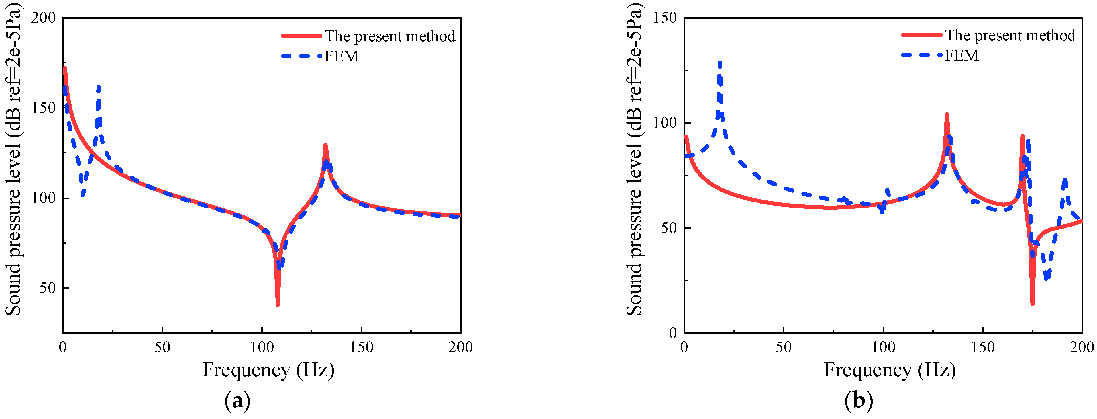
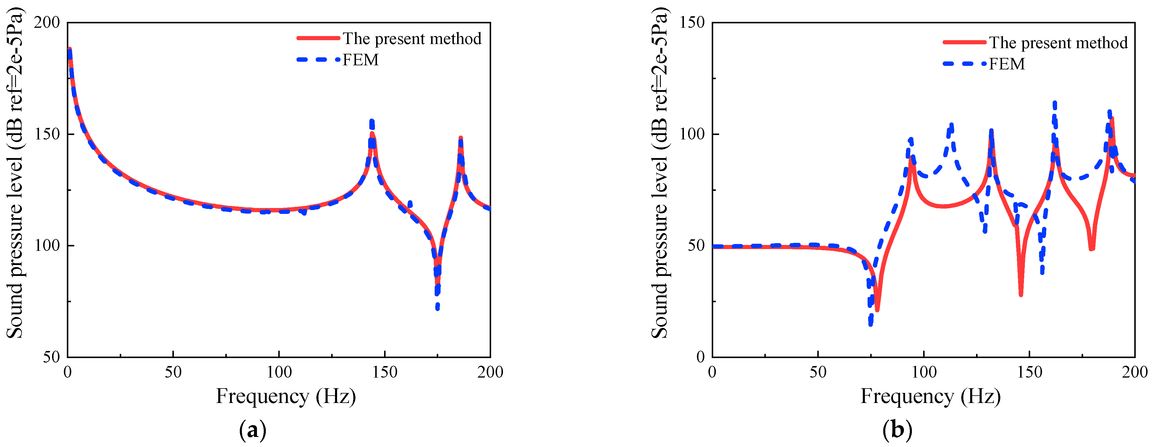
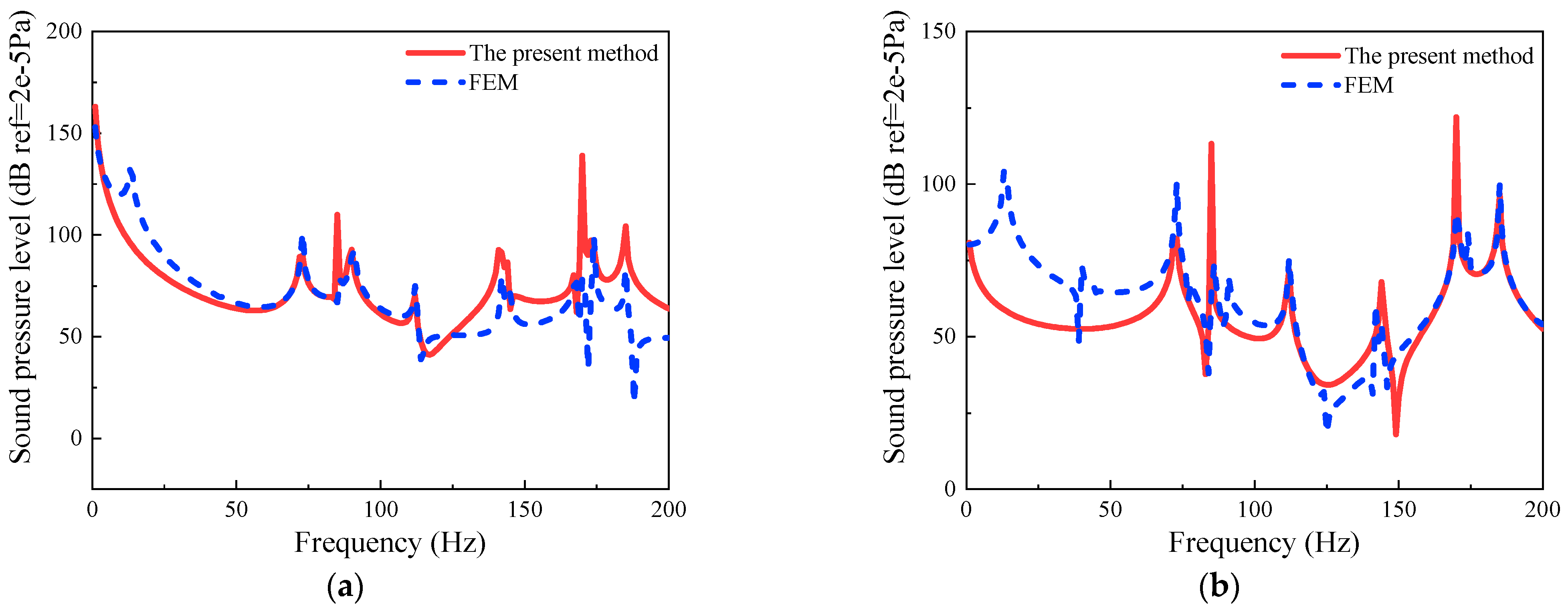
This section investigates the sound pressure response of the coupled system between the composite laminated rotationally stiffened plate and the cylindrical-cylindrical, spherical-cylindrical, and conical-cylindrical acoustic cavities under the point source or point force excitation. Figure 14 shows the sound pressure response curves at various observation points for the coupling system between the composite laminated rotationally stiffened plate and the cylindrical-cylindrical acoustic cavity under monopole point source or point force excitation. The boundaries of the composite laminated rotationally stiffened plate are SSSS, the number of stiffeners is n = 1, and the coupling system’s geometric parameters are as follows: R1 = 0.4 m, R2 = 1.2 m, L1 = 0.5 m, L2 = 1 m, hp = 0.02 m, ϑ = 90°, Rb1 = 0.8 m, b1 = 0.06 m, and h1 = 0.04 m. The material of the laminated plate is graphite epoxy resin, the layer angle is [0°/90°], the material of the laminated beam is steel, and the medium in the acoustic cavity is air. The point source is located at (0.69 m, 0.50 m, 0.38 m) within cylindrical cavity 1, and the point force is applied on the surface of the stiffened plate at (0.29 m, 0.93 m). Observation point 1 is located at (1.05 m, 0.34 m, 0.30 m) within cylindrical cavity 1, and observation point 2 is located at (0.96 m, 0.53 m, 0.55 m) within cylindrical cavity 2. From Figure 14, it can be observed that the response curves obtained by the present method are in good agreement with the finite element simulation results.
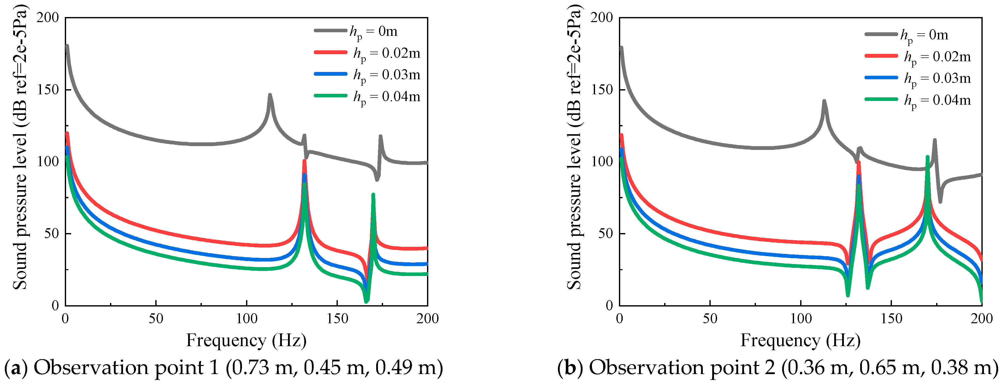
In the coupling system among the composite laminated rotationally stiffened plate and the cylindrical-cylindrical acoustic cavities, when the source excitation of the point sound and observation points are not in the same cavity, the sound pressure response of the coupled system will be influenced by the thickness (hp) of the composite stiffened plate among the two cavities. To investigate how the thickness of the composite stiffened plate affects the mechanism, Figure 15 provides sound pressure response curves at observation points within the lower cylindrical acoustic cavity 2 for various thicknesses of the composite stiffened plate when excited by the source of point sound in the upper cylindrical cavity 1. Here, hp = 0 m indicates that there is no composite stiffened plate between the two cavities. The relevant factors of the composite laminated rotationally stiffened plate and the cylindrical-cylindrical acoustic cavity are the same as in Figure 14. The point sound source is located at (0.53 m, 0.51 m, 0.32 m) within cylindrical cavity 1, observation point 1 is located at (0.73 m, 0.45 m, 0.49 m) within cylindrical cavity 2, and observation point 2 is located at (0.36 m, 0.65 m, 0.38 m) within cylindrical cavity 2.
From Figure 15, it can be observed that the sound pressure response curve’s amplitude at the same observation location declines as the thickness of the composite stiffened plate increases; there is a substantial difference in the sound pressure response with and without the composite stiffened plate. This result indicates that the composite stiffened plate in the coupling system has a specific influence on noise reduction, and this impact rises with the increasing thickness of the stiffened plate.
Figure 16 provides sound pressure response curves at observation points in the coupling system among the composite laminated rotationally stiffened plate and the spherical-cylindrical cavities under the monopole point source or point force excitation. The boundaries of the composite laminated rotationally stiffened plate are SSSS, the number of stiffeners n is 1, and the coupling system’s geometric parameters are: R1 = 0.4 m, R2 = 1.2 m, ϕ1 = 30°, ϕ2 = 90°, L = 1.8 m, hp = 0.02 m, ϑ = 90°, Rb1 = 0.8 m, b1 = 0.06 m, and h1 = 0.04 m. The material of the laminated plate is graphite epoxy resin, the layer angles are [0°/90°], the material of the laminated beam is steel, and the acoustic cavity is filled with air. The point sound source is located at (0.72 m, 0.26 m, 0.56 m) within spherical cavity 1, and the point force is located on the surface of the stiffened plate at (0.34 m, 0.72 m). Observation point 1 is located within the spherical cavity at (0.26 m, 0.99 m, 0.24 m), and observation point 2 is located within the cylindrical cavity at (0.96 m, 0.53 m, 1.15 m). As shown in Figure 16, the sound pressure response curves obtained using the present method are in good agreement with the finite element method results.
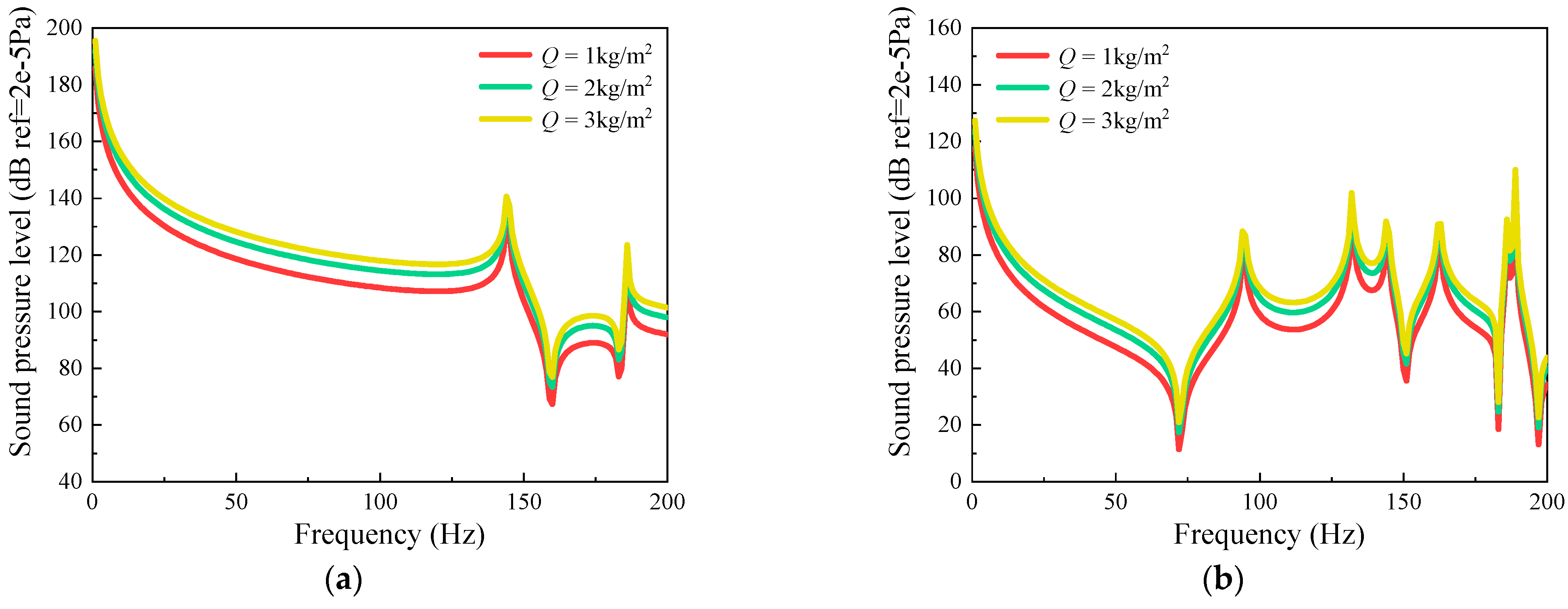
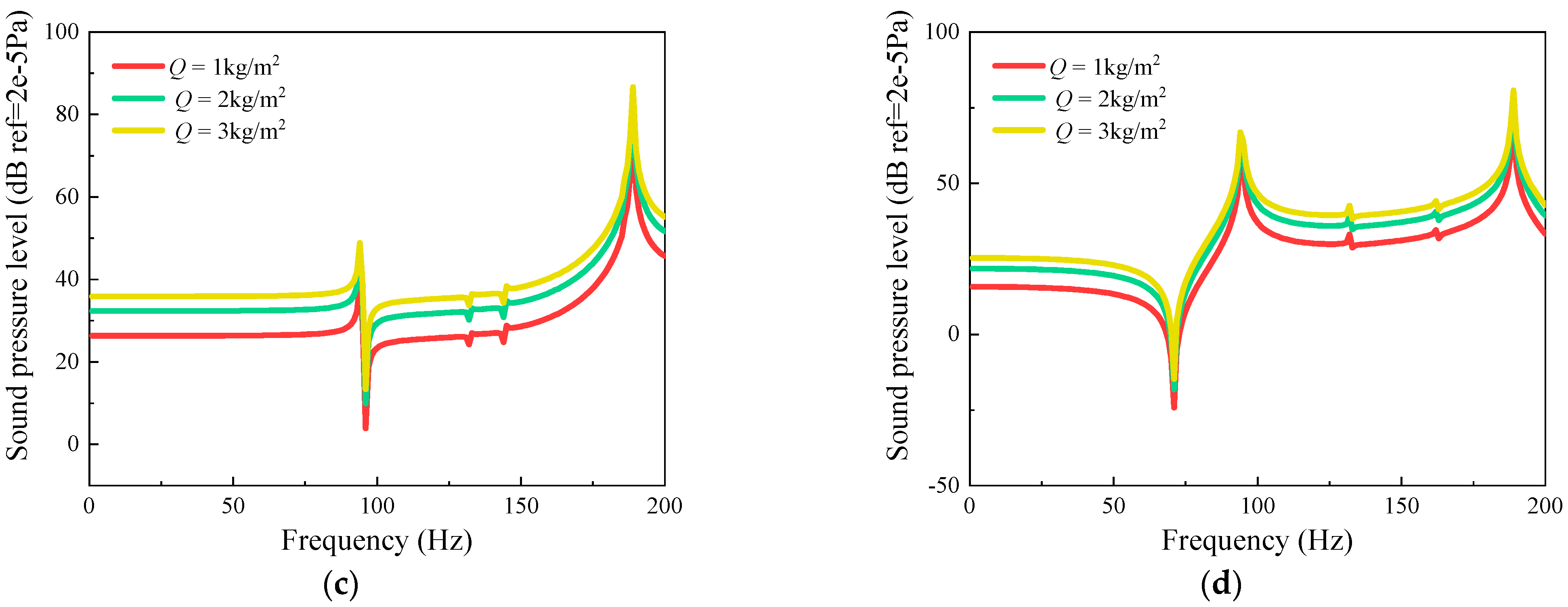
In this section, using the example of the coupling system between the composite laminated rotationally stiffened plate and the spherical-cylindrical cavity, we have studied the impact of the amplitude of a point source or point force excitation on the sound pressure response of the coupling system between the composite laminated rotationally stiffened plate and the cavity. Figure 17 illustrates the sound pressure response curves at various observation points of different amplitudes of the point source or the point force excitation. In this example, the relevant parameters of the coupled system between the composite laminated rotationally stiffened plate and spherical-cylindrical cavity are the same as in Figure 16. The amplitudes (A) of the point source or the point force excitation are set to 1 kg/s2, 2 kg/s2, and 3 kg/s2. The point source is located at (0.65 m, 0.32 m, 0.44 m) within the spherical cavity, and the point force is applied on the surface of the stiffened plate at (0.50 m, 0.50 m). Observation point 1 is within the spherical cavity at (0.45 m, 0.56 m, 0.40 m), and observation point 2 is within the cylindrical cavity at (0.75 m, 0.35 m, 0.60 m). As shown in Figure 17, variations in the amplitude of the point force or point source excitation lead to vertical shifts in the sound pressure response amplitude, and this effect increases with the increasing amplitude of the external point source excitation.
To validate whether the computed results obtained by the present method of the coupled system between the composite laminated rotationally stiffened plate and the conical-cylindrical cavity correspond to those obtained with the finite element method, Figure 18 presents the sound pressure response curves at various observation points of the single monopole point source or point force excitation. The boundaries of the composite laminated rotationally stiffened plate are set to SSSS; the number of stiffeners n is 1. The coupling system’s geometric parameters are: R1 = 0.6 m, R2 = 1.2 m, R3 = 1.8 m, α = 30°, L = 2 m, hp = 0.02 m, ϑ = 90°, Rb1 = 1.5 m, b1 = 0.06 m, and h1 = 0.04 m. The material of the laminated plate is graphite epoxy resin, with layer angles of [0°/90°], and the material of the laminated beam is Q235 steel. The acoustic cavity is filled with air. The point source is located at (1.13 m, 0.70 m, 0.61 m) within the conical cavity, and the point force is applied on the surface of the stiffened plate at (0.64 m, 1.41 m). Observation point 1 is within the conical cavity at (0.26 m, 1.53 m, 0.13 m), and observation point 2 is within the cylindrical cavity at (1.47 m, 0.40 m, 0.95 m). As shown in Figure 18, the sound pressure response curves obtained using the present method closely correspond to the results obtained using the finite element method.
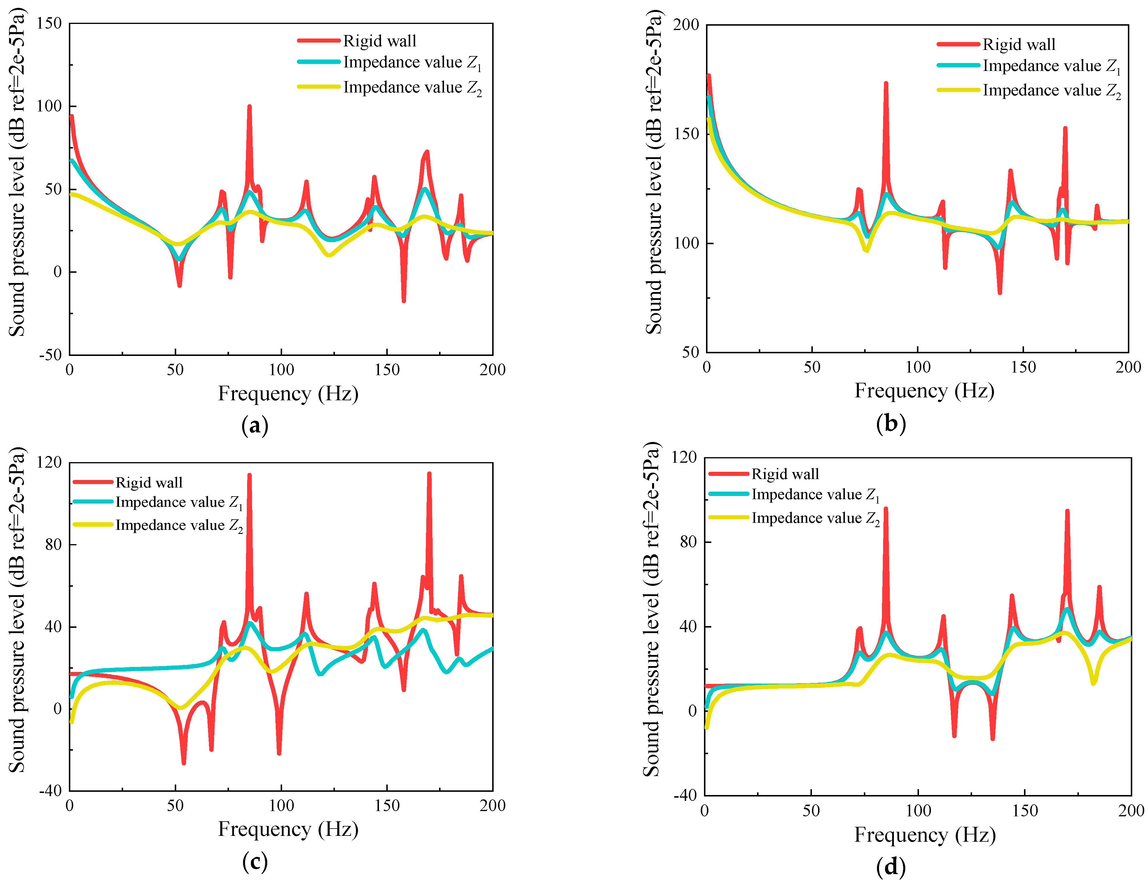
Figure 19 presents the sound pressure response of the coupling system among the composite laminated rotationally stiffened plate and the conical-cylindrical cavity under the excitation of a single monopole point source or a point force with different acoustic wall impedance values. In this coupled system, the acoustic wall surfaces have different impedance values; specifically, they are rigid: Z1 = ρcc0 (100 – j), and Z2 = ρcc0 (30 – j). The boundaries, the parameters of the geometric, the materials, and the layer angles are consistent with those in Figure 18. The point source is located in the cylindrical cavity at (0.75 m, 0.88 m, 0.45 m), and the point force is applied on the stiffened plate surface at (0.80 m, 1.05 m). Observation point 1 is situated in the conical cavity at (1.25 m, 0.45 m, 0.25 m), while observation point 2 is in the cylindrical cavity at (0.95 m, 0.50 m, 0.75 m).
As shown in Figure 19, changing the acoustic wall surfaces from rigid to impedance surfaces results in a reduction in the sound pressure response amplitude, achieving a resonance suppression effect. The influence on the sound pressure response decreases as the impedance value increases. However, the change in the acoustic wall impedance in the coupled system has no effect on the shape of the sound pressure response curves.

4. Conclusions

In this paper, a unified analysis model of the vibro-acoustic characteristics of the coupled system between the composite laminated rotationally stiffened plate and cavities is developed, encompassing three distinct system types. This model was established using a combination of the finite element method, the modified Fourier series, and the Rayleigh-Ritz method. First, utilizing the modified Fourier series method, we determined the allowable functions of sound pressure and displacement associated with rotationally cavities, laminated plates, and laminated beams. Second, we introduced the potential energy of coupling among the plate-cavity and plate-beam interfaces, thereby formulating the functional of the total energy of the entire coupling system. Third, to solve the energy equation that was formulated, the Rayleigh-Ritz method was employed. After conducting numerical analyses on various examples, a study was conducted on the vibro-acoustical characteristics of the coupled system between composite laminated rotationally stiffened plate and cylindrical-cylindrical, spherical-cylindrical, and conical-cylindrical cavities. The selection of the truncation value and convergence was discussed and the correctness of the unified analysis model was confirmed. The effects of various parameters on natural frequency and steady-state response were studied. The specific conclusions are as follows:
(1) When the truncation value of the allowable functions is set to MC × NC × QC = 4 × 4 × 4 and MS × NS = 18 × 18, the analytical model developed in this paper of the coupling system between the composite laminated rotationally stiffened plate and cavities demonstrates excellent convergence. The maximum error in natural frequencies compared to the finite element method results in the examples of this paper is 3.51%. Additionally, the spring stiffness values also converge when they reach 1012.
(2) In the validation of the model’s correctness through the pressure response test, the error between the experimental results of specific frequency sound pressure values and the results of the present method is 7.49%, confirming the correctness of the unified analysis model established in this paper.
(3) Under free vibration conditions, the natural frequencies of the coupling system among the composite laminated rotationally stiffened plate and cavities decrease with increasing rotation angle, decrease with increasing height of the cylindrical cavity, decrease with increasing height of the cylindrical cavity and the apex angle of the spherical cavity, decrease with increasing height of the cylindrical cavity and decreasing cone-apex angle of the conical cavity, and increase with increasing boundary spring stiffness values.
(4) In the coupled system between the composite laminated rotationally stiffened plate and cavities, the composite laminated rotationally stiffened plate has a certain impact on noise reduction, and this impact increases with the thickness of the stiffened plate. The sound pressure response amplitude increases with the increase in the amplitude of point sound sources and point force excitation. The sound pressure response amplitude decreases with decreasing impedance values, but it does not affect the response waveform.

Author Contributions

Conceptualization, L.H.; methodology, C.S.; software, C.J.; validation, Y.D.; formal analysis, Y.D.; investigation, Y.D.; resources, Y.D.; data curation, Y.D.; writing—original draft preparation, H.Z.; writing—review and editing, H.Z.; visualization, H.Z.; supervision, H.Z.; project administration, H.Z.; funding acquisition, H.Z. All authors have read and agreed to the published version of the manuscript.

Funding

This research was funded by National Natural Science Foundation of China (Grant No. 52005255), Natural Science Foundation of Jiangsu Province of China (Grant No. BK20200430).

Data Availability Statement

The data presented in this study are available on request from the corresponding author.

Acknowledgments

The authors gratefully acknowledge the financial support from the National Natural Science Foundation of China, and the Natural Science Foundation of the Jiangsu Province of China.

Conflicts of Interest

The authors declare that there are no conflicts of interest regarding the publication of this paper.

Nomenclature

RpRadius of laminated platehpThickness of laminated plate
RbnRadius of the NTH laminated curved beambnWidth of the NTH laminated curved beam
hnThickness of the NTH laminated curved beamϑRotation angle
ku, kv, kwBoundary linear spring stiffness value coupled in the beamKr, KθBoundary torsional spring stiffness value
k u c p , k v c p , k w c p The stiffness value of linear spring coupled in the beam K r c p , K θ c p The stiffness value of torsional spring coupled in the beam
k u c c p , k v c c p , k w c c p The stiffness value of the linear spring coupled with plate and beam K x c c p , K y c c p The stiffness value of the torsional spring coupled with plate and beam
Up, Vp, WpDisplacement component of laminated plateUbn, Vbn, WbnDisplacement component of laminated curved beam
Q i j k ¯ Correlation stiffness coefficientTTransformation matrix
θkThe Angle between the principal direction and the r direction Q i j k Material coefficient of the k layer
E1, E2Young’s modulusG12, G13, G23Shear modulus
μ12, μ21Poisson’s ratio κ s ¯ Shear correction factor
N L Number of floorsZkThe base thickness of the k layer
Zk+1Upper surface thickness coordinates T P Total kinetic energy of the laminated plate
T B n Total kinetic energy of the NTH laminated curved beam U P Total potential energy of the laminated plate
U B n Total potential energy of the NTH laminated curved beam U P - coupling Coupling potential energy of laminated plate
U B n - coupling Coupling potential energy of the NTH laminated curved beam U S P Potential energy of boundary spring
W P & B n Potential energy coupling between the plate and the NTH beam W F Work done by the harmonic point force F
ρ p k Material density of the k layer of laminates ρ b n k Material density of the k layer of laminated curved beams
U stretch Tensile potential energy U bend Bending potential energy
U s - b Bending coupled potential energyfiFunction of external load distribution
PmnTwo-dimensional unknown Fourier coefficient matrixQlOne-dimensional unknown Fourier coefficient matrix
K P Stiffness matrix of laminated plate K B n Stiffness matrix of the NTH laminated curved beam
M P Mass matrix of laminated plate M B n Mass matrix of the NTH laminated curved beam
C B n & P The coupling matrix between the NTH beam and the plateωNatural frequency
ΩFrequency parameterMp, NpTruncation value of the laminated plate
MbTruncation value of laminated curved beamRαMean radius of curvature in the α direction of the middle surface
RβMean radius of curvature in the β direction of the middle surfaceLαMedium surface α direction length dimension
LβMedium surface β direction length dimensionLzMiddle surface z direction length dimension
ζDamping valueHThickness of cavity
ϕApex angle of Spherical cavityLLength of cavity
αCone apex Angle of cone sound cavity U C n Total potential energy of cavity n
T C n Total kinetic energy of cavity n W wall n The energy consumed by the cavity n impedance wall
W coupling n The coupled potential energy of cavity n W sound n The work done by a point source in cavity n
W C 1 C 2 Potential energy coupling between cavities 1 and 2 ρ C n The density of acoustic media in cavity n
c n The speed at which sound waves travel in cavity njPure imaginary number
SrArea of the r-th acoustic wallZrImpedance value of the r-th acoustic wall
Q s n Distribution function of point sound source in cavity nAThe amplitude of the point sound source
kThe wave number of soundδcThree-dimensional Dirac function
KnStiffness matrix of sound cavity nMnMass matrix of cavity n
CnCoupling matrix of sound cavity nQnSound field source vector of cavity n
ZnImpedance matrix of the acoustic wall of cavity n C12, C21Coupling matrix between cavities 1 and 2
Mc, Nc, LcThe truncation value of the cavity

Appendix A

Fourier coefficients vectors, concrete expression of strain component, matrix C P & B and M B , and C B & P and K B :
Amn, Bmn, Cmn, Dmn, and Emn represent the unknown, two-dimensional Fourier coefficient vectors of the allowable displacement functions of the laminated plate. These parameters can be expressed as:
A m n = A 0 , 0 1 , , A 0 , n 1 , , A m , n 1 , , A M , N 1 , A 2 , 0 2 , , A 2 , n 2 , , A 2 , N 2 , , A 1 , N 2 , A 0 , 2 3 , A 0 , 1 3 , , A m , 2 3 , , A M , 1 3 T B m n = B 0 , 0 1 , , B 0 , n 1 , , B m , n 1 , , B M , N 1 , B 2 , 0 2 , , B 2 , n 2 , , B 2 , N 2 , , B 1 , N 2 , B 0 , 2 3 , B 0 , 1 3 , , B m , 2 3 , , B M , 1 3 T C m n = C 0 , 0 1 , , C 0 , n 1 , , C m , n 1 , , C M , N 1 , C 2 , 0 2 , , C 2 , n 2 , , C 2 , N 2 , , C 1 , N 2 , C 0 , 2 3 , C 0 , 1 3 , , C m , 2 3 , , C M , 1 3 T D m n = D 0 , 0 1 , , D 0 , n 1 , , D m , n 1 , , D M , N 1 , D 2 , 0 2 , , D 2 , n 2 , , D 2 , N 2 , , D 1 , N 2 , D 0 , 2 3 , D 0 , 1 3 , , D m , 2 3 , , D M , 1 3 T E m n = E 0 , 0 1 , , E 0 , n 1 , , E m , n 1 , , E M , N 1 , E 2 , 0 2 , , E 2 , n 2 , , E 2 , N 2 , , E 1 , N 2 , E 0 , 2 3 , E 0 , 1 3 , , E m , 2 3 , , E M , 1 3 T
Al, Bl, Cl, Dl, and El represent the unknown, one-dimensional Fourier coefficient vectors of the displacement allowance function of the laminated beam and can be expressed as:
A l = A 0 , A 1 , , A l , , A L , a 1 , a 2 T B l = B 0 , B 1 , , B l , , A L , b 1 , b 2 T C l = C 0 , C 1 , , C l , , C L , c 1 , c 2 T D l = D 0 , D 1 , , D l , , D L , d 1 , d 2 T E l = E 0 , E 1 , , E l , , E L , e 1 , e 2 T
A m t n t l t and B m t n t l t represent the unknown, three-dimensional Fourier coefficient vectors of the pressure, and these parameters can be expressed as:
A m t n t l t = A 0 , 0 , 0 1 , , A 0 , 0 , l t 1 , , A 0 , 0 , L t 1 , , A 0 , N t , L t 1 , , A m t , n t , l t 1 , , A M t , N t , L t 1 , A 2 , 0 , 0 2 , , A 2 , 0 , l t 2 , , A 2 , 0 , L t 2 , , A 2 , n t , l t 2 , , A 1 , n t , l t 2 , , A 1 , N t , L t 2 , A 0 , 2 , 0 3 , , A 0 , 2 , l t 3 , , A 0 , 2 , L t 3 , , A m t , 2 , l t 3 , , A m t , 1 , l t 3 , , A M t , 1 , L t 3 , A 0 , 0 , 2 4 , A 0 , 0 , 1 4 , , A 0 , N t , 2 4 , , A m t , n t , 2 4 , , A m t , n t , 1 4 , , A M t , N t , 1 4 , A 2 , 2 , 0 5 , , A 2 , 2 , l t 5 , , A 2 , 2 , L t 5 , , A 2 , 1 , l t 5 , , A 2 , 1 , L t 5 , , A 1 , 1 , L t 5 , A 2 , 0 , 2 6 , A 2 , 0 , 1 6 , , A 2 , n t , 2 6 , , A 2 , N t , 2 6 , , A 1 , n t , L t 6 , , A 1 , N t , 1 6 , A 0 , 2 , 2 7 , A 0 , 2 , 1 7 , , A m t , 2 , 2 7 , , A m t , 1 , 1 7 , , A M t , 2 , 2 7 , , A M t , 1 , 1 7 T B m t n t l t = B 0 , 0 , 0 1 , , B 0 , 0 , l t 1 , , B 0 , 0 , L t 1 , , B 0 , N t , L t 1 , , B m t , n t , l t 1 , , B M t , N t , L t 1 , B 2 , 0 , 0 2 , , B 2 , 0 , l t 2 , , B 2 , 0 , L t 2 , , B 2 , n t , l t 2 , , B 1 , n t , l t 2 , , B 1 , N t , L t 2 , B 0 , 2 , 0 3 , , B 0 , 2 , l t 3 , , B 0 , 2 , L t 3 , , B m t , 2 , l t 3 , , B m t , 1 , l t 3 , , B M t , 1 , L t 3 , B 0 , 0 , 2 4 , B 0 , 0 , 1 4 , , B 0 , N t , 2 4 , , B m t , n t , 2 4 , , B m t , n t , 1 4 , , B M t , N t , 1 4 , B 2 , 2 , 0 5 , , B 2 , 2 , l t 5 , , B 2 , 2 , L t 5 , , B 2 , 1 , l t 5 , , B 2 , 1 , L t 5 , , B 1 , 1 , L t 5 , B 2 , 0 , 2 6 , B 2 , 0 , 1 6 , , B 2 , n t , 2 6 , , B 2 , N t , 2 6 , , B 1 , n t , L t 6 , , B 1 , N t , 1 6 , B 0 , 2 , 2 7 , B 0 , 2 , 1 7 , , B m t , 2 , 2 7 , , B m t , 1 , 1 7 , , B M t , 2 , 2 7 , , B M t , 1 , 1 7 T
ε r p 0 , ε θ p 0 , γ r θ p 0 , γ r z p 0 , and γ θ z p 0 represent the strain components on the mid-surface of the laminated plate, while χ r p , χ θ p , and χ r θ p represent the curvature change component of the surface of the laminated plate; ε θ b n 0 , γ θ x b n 0 , γ θ z b n 0 , and γ x z b n 0 represent the strain component on the surface of the nth laminated curved beam. χ θ b n and χ θ x b n represent the component of curvature change in the surface of the laminated curved beam. The specific expressions are as follows:
ε r p 0 = u p r ε θ p 0 = v p r θ + u p r γ r θ p 0 = v p r + u p r θ v p r   γ r z p 0 = w p r + ϕ r p   γ θ z p 0 = ϕ θ p χ r p = ϕ r p r   χ r p = ϕ r p r   χ r θ p = ϕ θ p r + ϕ r p r θ ϕ θ p r
ε θ b n 0 = v b n R n θ n + w b n R n γ θ x b n 0 = u b n R n θ n   γ θ z p 0 = w b n R n θ n v b n R n + ϕ θ b n   γ x z b n 0 = ϕ x b n χ θ b n = ϕ θ b n R n θ n   χ θ x b n = ϕ x b n R n θ n
C P & B = C P & B 1 C P & B 2 C P & B 3 C P & B n C P & B N 1 C P & B N
M B = M B 1 0 0 M B 2 0 0 0 0 0 0 M B n 0 0 0 0 0 M B N 1 0 0 0 M B N
C B & P = C B 1 & P C B 2 & P C B 3 & P C B n & P C B N 1 & P C B N & P
K B = K B 1 0 0 0 0 0 0 0 0 K B 2 0 0 0 K B 3 0 0 0 0 0 0 K B n 0 0 0 0 0 0 0 K B N 1 0 0 0 0 K B N

References

  1. Shahraeeni, M.; Shakeri, R.; Hasheminejad, S.M. An analytical solution for free and forced vibration of a piezoelectric laminated plate coupled with an acoustic enclosure. Comput. Math. Appl. 2015, 69, 1329–1341. [Google Scholar] [CrossRef]
  2. Huang, H.; Zou, M.-S.; Jiang, L.-W. Study on the integrated calculation method of fluid–structure interaction vibration, acoustic radiation, and propagation from an elastic spherical shell in ocean acoustic environments. Ocean. Eng. 2019, 177, 29–39. [Google Scholar] [CrossRef]
  3. Qu, Y.; Meng, G. Nonlinear Vibro-Acoustic Analysis of Composite Sandwich Plates with Skin–Core Debondings. AIAA J. 2017, 55, 1723–1733. [Google Scholar] [CrossRef]
  4. Seçgin, A.; Kara, M.; Ozankan, A. A modal impedance-based statistical energy analysis for vibro-acoustic analysis of complex systems having structural uncertainty. Proc. Inst. Mech. Eng. Part C J. Mech. Eng. Sci. 2019, 233, 1972–1989. [Google Scholar] [CrossRef]
  5. Sarıgül, A.S.; Karagözlü, E. Vibro-acoustic coupling in composite plate-cavity systems. J. Vib. Control 2018, 24, 2274–2283. [Google Scholar] [CrossRef]
  6. Dozio, L.; Alimonti, L. Variable kinematic finite element models of multilayered composite plates coupled with acoustic fluid. Mech. Adv. Mater. Struct. 2016, 23, 981–996. [Google Scholar] [CrossRef]
  7. Sharma, N.; Mahapatra, T.R.; Panda, S.K. Vibro-acoustic analysis of un-baffled curved composite panels with experimental validation. Struct. Eng. Mech. Int. J. 2017, 64, 93–107. [Google Scholar]
  8. Balakrishnan, B.; Raja, S.; Dwarakanathan, D.; Rajagopal, A. Vibroacoustic performance of fiber metal laminates with delamination. Mech. Adv. Mater. Struct. 2016, 23, 1369–1378. [Google Scholar] [CrossRef]
  9. Xin, F.X.; Lu, T.J. Analytical modeling of fluid loaded orthogonally rib-stiffened sandwich structures: Sound transmission. J. Mech. Phys. Solids 2010, 58, 1374–1396. [Google Scholar] [CrossRef]
  10. Fu, T.; Chen, Z.; Yu, H.; Li, C.; Liu, X. An analytical study of the vibroacoustic response of a ribbed plate. Aerosp. Sci. Technol. 2018, 73, 96–104. [Google Scholar] [CrossRef]
  11. Zhao, D.; Squicciarini, G.; Ferguson, N.S. The acoustic response of stiffened plates. J. Phys. Conf. Ser. 2019, 1264, 012041. [Google Scholar] [CrossRef]
  12. Abedini Baghbadorani, A.; Kiani, Y. Free vibration analysis of functionally graded cylindrical shells reinforced with graphene platelets. Compos. Struct. 2021, 276, 114546. [Google Scholar] [CrossRef]
  13. Shi, D.; Zha, S.; Zhang, H.; Wang, Q. Free Vibration Analysis of the Unified Functionally Graded Shallow Shell with General Boundary Conditions. Shock Vib. 2017, 2017, 7025190. [Google Scholar] [CrossRef]
  14. Shi, D.; Zhang, H.; Wang, Q.; Zha, S. Free and Forced Vibration of the Moderately Thick Laminated Composite Rectangular Plate on Various Elastic Winkler and Pasternak Foundations. Shock Vib. 2017, 2017, 7820130. [Google Scholar] [CrossRef]
  15. Petyt, M. Vibration of curved plates. J. Sound Vib. 1971, 15, 381–395. [Google Scholar] [CrossRef]
  16. Wang, Q.; Choe, K.; Shi, D.; Sin, K. Vibration analysis of the coupled doubly-curved revolution shell structures by using Jacobi-Ritz method. Int. J. Mech. Sci. 2018, 135, 517–531. [Google Scholar] [CrossRef]
  17. Wang, Q.; Cui, X.; Qin, B.; Liang, Q. Vibration analysis of the functionally graded carbon nanotube reinforced composite shallow shells with arbitrary boundary conditions. Compos. Struct. 2017, 182, 364–379. [Google Scholar] [CrossRef]
  18. Wang, Q.; Cui, X.; Qin, B.; Liang, Q.; Tang, J. A semi-analytical method for vibration analysis of functionally graded (FG) sandwich doubly-curved panels and shells of revolution. Int. J. Mech. Sci. 2017, 134, 479–499. [Google Scholar] [CrossRef]
  19. Guo, C.; Liu, T.; Wang, Q.; Qin, B.; Shao, W.; Wang, A. Spectral-Tchebychev technique for the free vibration analysis of composite laminated stepped and stiffened cylindrical shells with arbitrary boundary conditions. Compos. Struct. 2021, 272, 114193. [Google Scholar]
  20. Zhang, H.; Shi, D.; Zha, S.; Wang, Q. Vibro-acoustic analysis of the thin laminated rectangular plate-cavity coupling system. Compos. Struct. 2018, 189, 570–585. [Google Scholar] [CrossRef]
  21. Zhang, H.; Shi, D.; Zha, S.; Wang, Q. Parameterization study on the moderately thick laminated rectangular plate-cavity coupling system with uniform or non-uniform boundary conditions. Compos. Struct. 2018, 194, 537–554. [Google Scholar] [CrossRef]
  22. Chen, T.; Zhang, H.; Ren, W.; Shi, D.; Huang, B. The modeling method of anisotropic U-shaped plate and U-shaped plate–cavity coupled system. Thin-Walled Struct. 2022, 172, 108880. [Google Scholar] [CrossRef]
  23. Zhang, H.; Chen, T. Vibro-acoustic characteristics analysis of the rotary composite plate and conical–cylindrical double cavities coupled system. J. Intell. Manuf. Spec. Equip. 2022, 3, 67–96. [Google Scholar] [CrossRef]
  24. Esmaeili, H.R.; Kiani, Y.; Beni, Y.T. Vibration characteristics of composite doubly curved shells reinforced with graphene platelets with arbitrary edge supports. Acta Mech. 2022, 233, 665–683. [Google Scholar] [CrossRef]
  25. Zhou, Y.; Wang, Q.; Shi, D.; Liang, Q.; Zhang, Z. Exact solutions for the free in-plane vibrations of rectangular plates with arbitrary boundary conditions. Int. J. Mech. Sci. 2017, 130, 1–10. [Google Scholar] [CrossRef]
  26. Zhong, R.; Wang, Q.; Tang, J.; Shuai, C.; Qin, B. Vibration analysis of functionally graded carbon nanotube reinforced composites (FG-CNTRC) circular, annular and sector plates. Compos. Struct. 2018, 194, 49–67. [Google Scholar] [CrossRef]
  27. Thomas, B.; Roy, T. Vibration analysis of functionally graded carbon nanotube-reinforced composite shell structures. Acta Mech. 2016, 227, 581–599. [Google Scholar] [CrossRef]
  28. Gurve, H.K.; Satankar, R.K. Free vibration analysis of curved shells using finite element method. Mater. Today Proc. 2022, 50, 2336–2344. [Google Scholar] [CrossRef]
Figure 1. Geometric parameters and the coordinate system of a double-curvature cavity unit cross-section.
Applsci 14 01002 g001
Figure 2. Coordinate transformation diagram of the parallelogram section.
Applsci 14 01002 g002
Figure 3. Model of the coupled system between the composite laminated rotationally stiffened plate and the acoustic cavities.
Applsci 14 01002 g003
Figure 4. The boundary spring and the coupling spring of the composite laminated rotationally stiffened plate.
Applsci 14 01002 g004
Figure 5. Variation curves of the natural frequencies of the coupled system between the composite, laminated rotational plate and the cylindrical-spherical cavities under different boundary spring stiffness values.
Applsci 14 01002 g005
Figure 6. Variation curves of the natural frequencies of the coupling system among the composite laminated rotationally stiffened plate and the cylindrical-cylindrical cavities under different plate-beam coupling spring stiffness values for two boundary conditions.
Applsci 14 01002 g006
Figure 7. The test schematic diagram of the coupled system between the circular stiffened plate, the cylindrical cavity, and the software parameter interface.
Applsci 14 01002 g007
Figure 8. The arrangement of the coupled system between the circular stiffened plate, the cylindrical cavity, and the experimental instruments in the sound pressure response test.
Applsci 14 01002 g008
Figure 9. Sound pressure comparison between the experimental measurements and the results obtained using the present method of the coupled system between the circular stiffened plate and the cylindrical cavity at specific frequencies and at different observation points.
Applsci 14 01002 g009
Figure 10. Variation curve of the natural frequencies of the coupling system among the composite laminated rotationally stiffened plate and the cylindrical-cylindrical cavity at different rotation angles.
Applsci 14 01002 g010
Figure 11. Trends of the first four natural frequencies of the coupling system among the composite laminated rotationally stiffened plate and the cylindrical-cylindrical cavities as the height of the cylindrical cavities L1 and L2 vary.
Applsci 14 01002 g011aApplsci 14 01002 g011b
Figure 12. Trends of the first four natural frequencies of the coupled system between the composite laminated rotationally stiffened plate and the spherical-cylindrical cavity as height L of the cylindrical cavity and the top angle ϕ of the spherical cavity vary.
Applsci 14 01002 g012aApplsci 14 01002 g012b
Figure 13. Trends of the first four natural frequencies of the coupled system between the composite laminated rotationally stiffened plate and the conical-cylindrical cavity as height L2 of the cylindrical cavity and the cone top angle α of the conical cavity vary.
Applsci 14 01002 g013aApplsci 14 01002 g013b
Figure 14. (a) Sound pressure response of observation point 1 under the point sound source. (b) Sound pressure response of observation point 2 under the point force. Sound pressure response curves at various observation points for the coupled system between the composite laminated rotationally stiffened plate and the cylindrical-cylindrical acoustic cavity under the monopole point source or point force excitation.
Applsci 14 01002 g014
Figure 15. Sound pressure response curves at observation points within the lower cylindrical acoustic cavity 2 for different thicknesses of the composite stiffened plate when excited by a point sound source in upper cylindrical cavity 1.
Applsci 14 01002 g015
Figure 16. (a) Sound pressure response of observation point 1 under the point sound source. (b) Sound pressure response of observation point 2 under the point force. Sound pressure response curves at observation points in the coupling system among the composite laminated rotationally stiffened plate and the spherical-cylindrical cavities under the monopole point source or point force excitation.
Applsci 14 01002 g016
Figure 17. (a) Sound pressure response of observation point 1 under the point sound source. (b) Sound pressure response of observation point 2 under point sound source. (c) Sound pressure response of observation point 1 under the point force. (d) Sound pressure response of observation point 2 under the point force. Sound pressure response curves of the coupling system between the composite laminated rotationally stiffened plate and the spherical-cylindrical cavity at various observation points of different amplitudes of the point source or point force excitation.
Applsci 14 01002 g017aApplsci 14 01002 g017b
Figure 18. (a) Sound pressure response of observation point 1 under the point sound source. (b) Sound pressure response of observation point 2 under the point force. Sound pressure response curves of the coupling system between the composite laminated rotationally stiffened plate and the conical-cylindrical cavity at various observation points of the single monopole point source or point force excitation.
Applsci 14 01002 g018
Figure 19. (a) Sound pressure response of observation point 1 under the point sound source. (b) Sound pressure response of observation point 1 under the point sound source. (c) Sound pressure response of observation point 1 under the point force. (d) Sound pressure response of observation point 2 under the point force. Sound pressure response of the coupling system among the composite laminated rotationally stiffened plate and the conical-cylindrical cavity under the excitation of a single monopole point source or a point force with different acoustic wall impedance values.
Applsci 14 01002 g019
Table 1. Related parameters of conversion between the cylinder-cylinder cavity, the spherical-cylinder cavity, and the cone-cylinder cavity coupling systems.
System TypeParameter
cylinder-cylinder cavity coupling system(1) α 1 = s 1 , β 1 = θ 1 , z 1 = r 1 ; α 2 = s 2 , β 2 = θ 2 , z 2 = r 2
(2) H α 1 = 1 , H β 1 = r 1 , H z 1 = 1 ; H α 2 = 1 , H β 2 = r 2 , H z 2 = 1
(3) L α 1 = L 1 , L β 1 = ϑ 1 , L z 1 = H ; L α 2 = L 2 , L β 2 = ϑ 2 , L z 2 = H
(4) J 1 = 1 , J 11 1 = J 22 1 = 2 / 2 , J 12 1 = J 21 1 = 0 ;
    J 2 = 1 , J 11 2 = J 22 2 = 2 / 2 , J 12 2 = J 21 2 = 0
spherical-cylinder cavity coupling system(1) α 1 = φ 1 , β 1 = θ 1 , z 1 = r 1 ; α 2 = s 2 , β 2 = θ 2 , z 2 = r 2
(2) H α 1 = r 1 , H β 1 = r sin φ 1 , H z 1 = 1 ; H α 2 = 1 , H β 2 = r 2 , H z 2 = 1
(3) L α 1 = ϕ , L β 1 = ϑ 1 , L z 1 = H ; L α 2 = L 2 , L β 2 = ϑ 2 , L z 2 = H
(4) J 1 = 1 , J 11 1 = J 22 1 = 2 / 2 , J 12 1 = J 21 1 = 0 ;
    J 2 = 1 , J 11 2 = J 22 2 = 2 / 2 , J 12 2 = J 21 2 = 0
cone-cylinder cavity coupling system(1) α 1 = η 1 , β 1 = θ 1 , z 1 = ξ 1 ; α 2 = s 2 , β 2 = θ 2 , z 2 = r 2
(2) H α 1 = 1 , H β 1 = r 1 = R 2 + R 1 R 2 η + H ξ , H z 1 = 1 ;
    H α 2 = 1 , H β 2 = r 2 , H z 2 = 1
(3) L α 1 = 1 , L β 1 = ϑ 1 , L z 1 = 1 ; L α 2 = L 2 , L β 2 = ϑ 2 , L z 2 = H
(4) J 1 = L 1 H cos α , J 11 1 = 1 / H , J 21 1 = tan α / H , J 12 1 = 0 ,
    J 22 1 = 1 / L 1 cos α ; J 2 = 1 , J 11 2 = J 22 2 = 2 / 2 , J 12 2 = J 21 2 = 0
Table 2. The material parameters used in the numerical calculations in this paper.
Materialρ (kg/m3)Material Property Parameter
E1 (Pa)E2 (Pa)G23 (Pa)G12(Pa)G13 (Pa)μ12
Graphite fiber resin16001.85 × 10111.09 × 10107.3 × 1097.3 × 1097.3 × 1090.28
Glass epoxy resin18103.9 × 10108.4 × 1094.2 × 10104.2 × 10104.2 × 10100.26
Q235 steel78002.16 × 10112.16 × 10118.31 × 10108.31 × 10108.31 × 10100.3
Table 3. Convergence analysis of the coupling system among the composite laminated rotationally stiffened plate and the cylindrical-cylindrical cavities.
Mc × Nc × QcMp × NpModal Order
12345678
3 × 3 × 310 × 1082.33 132.23 132.24 169.89 210.59 215.29 221.15 221.27
12 × 1281.78 132.23 132.24 169.89 210.30 215.28 221.15 221.27
14 × 1481.32 132.23 132.29 169.86 210.01 215.28 221.14 221.27
16 × 1680.95 132.21 132.24 169.89 209.78 215.27 221.14 221.27
18 × 1880.64 132.18 132.23 169.89 209.54 215.27 221.14 221.27
4 × 4 × 410 × 1082.33 132.24 132.25 169.89 210.59 215.28 221.17 221.27
12 × 1281.78 132.23 132.24 169.90 210.30 215.28 221.14 221.27
14 × 1481.32 132.22 132.24 169.89 210.01 215.28 221.17 221.27
16 × 1680.95 132.17 132.36 169.88 209.77 215.27 221.14 221.27
18 × 1880.64 132.29 132.33 169.88 209.54 215.27 221.24 221.27
5 × 5 × 510 × 1082.33 132.24 132.26 169.89 210.59 215.28 221.15 221.27
12 × 1281.78 132.23 132.24 169.89 210.30 215.28 221.15 221.27
14 × 1481.32 132.22 132.24 169.89 210.01 215.28 221.14 221.27
16 × 1680.95 132.21 132.24 169.89 209.77 215.27 221.14 221.27
18 × 1880.64 132.15 132.23 169.88 209.54 215.27 221.14 221.27
FEM82.33 132.24 132.26 169.89 210.59 215.28 221.15 221.27
Table 4. Convergence analysis of the coupling system among the composite laminated rotationally stiffened plate and the cylindrical-spherical cavities.
Mc × Nc × QcMp × NpModal Order
12345678
3 × 3 × 310 × 1083.63 113.18 132.05 144.43 174.01 185.80 212.10 221.18
12 × 1282.77 113.18 132.05 144.39 173.99 185.80 211.90 221.18
14 × 1482.04 113.19 132.03 144.36 174.01 185.80 211.65 221.18
16 × 1681.45 113.18 132.01 144.33 173.96 185.79 211.48 221.17
18 × 1880.93 113.16 131.99 144.22 173.95 185.80 211.27 221.18
4 × 4 × 410 × 1083.59 113.18 132.03 144.42 174.00 185.80 209.37 221.17
12 × 1282.74 113.17 132.01 144.38 173.98 185.81 209.24 221.16
14 × 1482.02 113.23 131.99 144.39 173.96 185.80 209.07 221.16
16 × 1681.42 113.13 131.97 144.31 173.98 185.80 208.97 221.15
18 × 1880.91 113.21 131.93 144.33 173.96 185.80 208.83 221.15
5 × 5 × 510 × 1083.59 113.18 132.03 144.40 174.00 185.79 209.29 221.17
12 × 1282.73 113.18 132.01 144.38 173.98 185.79 209.16 221.17
14 × 1482.01 113.17 131.99 144.39 173.96 185.79 208.99 221.16
16 × 1681.42 113.18 131.96 144.34 173.95 185.80 208.89 221.16
18 × 1880.91 113.18 131.93 144.32 173.94 185.80 208.75 221.15
FEM82.42113.65132.18144.20173.89185.89206.74221.19
Table 5. Convergence analysis of the coupling system among the composite laminated rotationally stiffened plate and the cylindrical-conical cavities.
Mc × Nc × QcMp × NpModal Order
12345678
3 × 3 × 310 × 1072.86 84.98 89.62 95.60 111.71 131.07 141.42 144.26
12 × 1272.56 85.03 89.62 95.09 111.71 130.72 141.42 144.27
14 × 1472.53 84.98 89.66 94.58 111.70 130.35 141.42 144.26
16 × 1672.52 84.96 89.62 94.18 111.70 130.08 141.42 144.26
18 × 1872.51 84.98 89.65 93.78 111.70 129.79 141.42 144.29
4 × 4×410 × 1072.86 84.95 89.63 95.60 111.71 131.07 141.42 144.27
12 × 1272.56 84.98 89.62 95.09 111.70 130.72 141.42 144.27
14 × 1472.53 85.02 89.62 94.58 111.70 130.35 141.42 144.26
16 × 1672.52 85.01 89.62 94.18 111.70 130.08 141.42 144.26
18 × 1872.51 84.98 89.61 93.78 111.70 129.79 141.42 144.26
5 × 5×510 × 1072.85 85.02 89.62 95.60 111.71 131.07 141.40 144.27
12 × 1272.56 84.98 89.62 95.09 111.71 130.72 141.40 144.26
14 × 1472.53 84.95 89.62 94.58 111.70 130.35 141.40 144.26
16 × 1672.53 84.93 89.62 94.17 111.70 130.08 141.40 144.27
18 × 1872.52 84.98 89.62 93.78 111.70 129.79 141.40 144.26
FEM72.4884.0489.4690.60111.49130.89141.63144.27
Table 6. The stiffness value of the boundary spring under different boundary conditions.
Boundary ConditionThe Stiffness Value of the Boundary Spring
kukvkwKrKθ
C10161016101610161016
S10161016101600
F00000
E1108108108108108
E210610610600
Table 7. Natural frequencies of the coupling system among the composite laminated rotationally stiffened plate and the cylindrical-cylindrical cavities at different rotation angles.
Rotation Angle ϑModal Order
12345678
45°85.00 155.58 155.58 169.99 170.00 177.30 192.19 192.20
90°80.60 80.62 85.00 117.13 155.58 155.58 169.99 169.99
135°54.13 54.15 84.99 100.78 106.37 106.38 136.16 155.57
180°40.72 40.73 80.60 80.60 84.99 94.25 117.13 118.98
225°32.60 32.62 64.80 64.81 84.99 91.04 96.15 96.16
270°27.21 27.22 54.16 54.16 80.60 80.61 84.98 89.24
315°23.32 23.33 46.49 46.50 69.34 69.35 84.94 88.14
360°40.71 40.73 40.88 40.94 46.37 79.98 80.60 80.60
Table 8. Natural frequencies of the coupling system among the composite laminated rotationally stiffened plate and the spherical-cylindrical cavities at different rotation angles.
Rotation Angle ϑModal Order
12345678
45°85.21 120.15 155.55 167.37 169.99 177.25 192.20 197.54
90°80.57 84.94 91.78 117.15 120.09 155.64 157.96 167.33
135°54.51 62.77 84.67 101.03 106.46 118.36 120.05 136.82
180°40.55 47.83 81.04 85.00 91.51 94.32 117.22 118.78
225°33.78 36.13 64.85 74.81 85.06 91.10 96.26 106.92
270°27.07 32.53 54.30 62.82 80.64 85.06 89.60 90.75
315°22.97 26.34 46.46 54.80 69.30 79.89 84.99 87.91
360°39.78 40.84 47.76 47.91 47.97 80.52 83.49 85.04
Table 9. Natural frequencies of the coupling system among the composite laminated rotationally stiffened plate and conical-cylindrical cavities at different rotation angles.
Rotation Angle ϑModal Order
12345678
45°85.15 141.85 144.06 167.83 168.87 169.93 222.99 243.87
90°72.43 85.03 89.84 111.83 142.29 143.89 167.78 169.52
135°48.20 60.57 85.21 96.57 98.19 118.24 128.03 142.61
180°36.48 44.39 72.36 85.39 87.11 92.59 108.35 111.85
225°28.48 37.10 58.33 73.33 84.86 87.26 89.65 102.84
270°24.76 28.97 48.03 61.36 72.35 85.09 88.39 90.03
315°23.33 23.61 41.37 49.49 62.27 76.84 83.38 85.25
360°36.37 38.22 42.77 44.80 60.53 72.71 83.96 84.22
Table 10. The natural frequencies of the coupling system between the composite laminated rotationally stiffened plate and the acoustic cavity under different boundary conditions.
Boundary ConditionTypeModal Order
12345678
SFSFCylindrical-Cylindrical40.72 40.72 80.60 80.61 84.44 85.79 94.26 117.14
Spherical-Cylindrical40.22 45.54 80.32 84.99 91.37 94.36 117.49 118.88
Conical-Cylindrical36.96 41.79 72.51 85.06 89.66 92.25 108.49 112.10
FFFSCylindrical-Cylindrical40.63 40.67 61.31 80.56 80.60 84.99 94.25 117.14
Spherical-Cylindrical40.46 47.00 80.59 85.02 91.73 94.41 117.23 119.00
Conical-Cylindrical35.55 45.95 72.03 85.57 89.88 92.68 108.50 112.31
SCSFCylindrical-Cylindrical40.72 40.73 80.60 80.60 84.99 94.24 108.33 117.13
Spherical-Cylindrical40.22 45.54 80.32 84.99 91.37 94.36 117.49 118.88
Conical-Cylindrical38.03 41.31 72.61 84.63 89.80 92.30 108.39 111.61
SCSCCylindrical-Cylindrical40.73 40.73 80.60 80.63 85.00 94.24 117.13 118.97
Spherical-Cylindrical40.26 46.28 80.29 84.91 91.50 94.17 117.48 118.83
Conical-Cylindrical38.51 40.80 74.63 83.79 90.86 95.28 106.32 112.51
CCCCCylindrical-Cylindrical40.73 40.74 80.55 80.60 85.00 94.25 117.14 118.98
Spherical-Cylindrical41.07 46.98 80.78 85.11 91.16 94.19 117.98 118.55
Conical-Cylindrical38.57 45.26 67.83 80.51 87.18 92.83 108.57 112.34
E1E1E1E1Cylindrical-Cylindrical40.71 40.72 69.96 80.60 80.62 85.06 94.24 117.13
Spherical-Cylindrical41.36 46.99 80.51 85.05 91.90 94.21 117.13 119.08
Conical-Cylindrical38.96 44.47 72.59 86.07 89.47 90.95 104.14 111.78
E2E2E2E2Cylindrical-Cylindrical40.71 40.90 68.34 80.60 80.63 85.13 94.22 117.13
Spherical-Cylindrical41.30 47.06 80.44 84.95 91.58 94.04 117.13 119.00
Conical-Cylindrical37.39 44.33 72.77 85.70 87.06 92.05 108.37 111.80
Disclaimer/Publisher’s Note: The statements, opinions and data contained in all publications are solely those of the individual author(s) and contributor(s) and not of MDPI and/or the editor(s). MDPI and/or the editor(s) disclaim responsibility for any injury to people or property resulting from any ideas, methods, instructions or products referred to in the content.