Article

An Experimental Demonstration of 2D-Multiple-Input-Multiple-Output-Based Deep Learning for Optical Camera Communication

Department of Electronics Engineering, Kookmin University, Seoul 02707, Republic of Korea
*
Author to whom correspondence should be addressed.
Appl. Sci. 2024, 14(3), 1003; https://doi.org/10.3390/app14031003
Submission received: 19 December 2023 / Revised: 22 January 2024 / Accepted: 22 January 2024 / Published: 24 January 2024

Abstract

:
Currently, radio frequency (RF) waveforms are widely used in wireless communication systems and are widely used in many fields to improve human quality of life. In Internet of Things (IoT) systems and satellite systems, the installation and deployment of wireless communication systems have become easier and offer many advantages compared to wired communication. However, high RF frequencies can have detrimental effects on the human body. Therefore, the visible light bandwidth is being researched and used as a replacement for RF in certain wireless communication systems. Several strategies have been explored: free-space optics, light fidelity, visible light communication, and optical camera communication. By leveraging time-domain on–off keying, this article presents a multiple-input-multiple-output (MIMO) modulation technique using a light-emitting diode (LED) array designed for IoT applications. The proposed scheme is versatile and suitable for both roller shutter and global shutter cameras commonly found on the market, including CCTV cameras commonly found in factories and buildings. By using deep learning for threshold prediction, the proposed scheme could achieve better performance compared to the traditional scheme. Despite the compact size of the LED array, the precise control of the exposure time, camera focal length, and channel encoding enabled the successful implementation of this scheme and supported four links at various positions within a communication distance of 22 m, taking into account the mobility effect (3 m/s).

1. Introduction

Currently, the development of wireless communication has become a key development in the history of contemporary technology and significantly advances the idea of a smart world. It has revolutionized traditional forms of information exchange and is now essential for the development and implementation of intelligent systems due to its seamless and ubiquitous connectivity [1]. The development of wireless communication technologies has led to the proliferation of Internet of Things (IoT) systems in various global domains. These IoT systems have become commonplace and are widely used in many areas of daily life, such as smart homes, smart transportation, e-health systems, smart factories, and environmental monitoring systems [2]. Modular devices, sensors, and microcontroller units make up the IoT infrastructure, which also includes components, such as human participants, plants, and animals. Its basic architecture aims to automatically enable global networking; however, this could harm human-to-human interactions and even reduce direct human interaction. The IoT plays a central role in the fourth industrial revolution and acts as a crucial enabler for the easy creation of international connections. The foundation of IoT is formed by various wireless communication technologies, most of which are characterized by radio frequency (RF) waveforms. Examples of these technologies include Wi-Fi, Bluetooth Low Energy, LoRa, 5G, and ZigBee [3]. The complexity of the IoT ecosystem is highlighted by this technologically diverse framework. Nevertheless, the harmful effects of radio waves on human physiology and health must be carefully considered when implementing wireless communication applications. Acceptable radio frequencies pass through the human body, which constitutes the operating environment. This medium is penetrated by electromagnetic waves, particularly those in the RF electromagnetic field, which directly affect people’s physical and mental health, as well as their neurological systems [4].
The global research community is currently dedicated to exploring and developing new technologies that can effectively replace RF techniques in specific applications. The potential risks and harmful effects of RF systems have motivated and driven researchers to seek alternatives that prioritize safety and minimize potential dangers. Accordingly, optical wireless communication (OWC) offers a promising alternative to traditional RF techniques owing to its utilization of visible light. There are four approaches for transmitting data in the OWC domain using light-emitting diodes (LEDs): optical camera communication (OCC), visible light communication (VLC), free space optical (FSO), and light fidelity (Li-Fi) [5]. With the advancement of technology, several technologies, such as FSO, Li-Fi, and VLC, have developed remarkably. With photodiodes serving as the receivers, these technologies have opened up new avenues for communication. In addition, the image sensor, which serves as a detector on the receiving end, is one of the OCC system’s most important parts. There are two well-known types of commercially available cameras that can be used in OCC systems: the global shutter camera and the rolling shutter camera. There are two widely used camera types in the market today: the global-shutter camera and the rolling-shutter camera. In the global-shutter camera, the performance of on-chip calibration (OCC) is mainly influenced by the camera frame rate, determining if the sampling rate meets the Nyquist sampling requirement. Similarly, in the rolling-shutter camera, the sampling rate is influenced by both the camera frame rate and the rolling rate. Depending on the OCC modulation scenarios, the camera type is selected and designed for specific applications. Compared to other types of OWC advances, OCC’s advantages in terms of cost, prominence, and data transmission limit have attracted impressive engagement areas, such as indoor localization, motion capture, intelligent transport frameworks, and especially, IoT systems [6]. Below are the advantages of OWC systems over RF systems.
  • Wireless communication often uses RF waves, leveraging their far-reaching benefits. However, they come with two notable drawbacks: detrimental effects on human well-being and lack of effectiveness against electromagnetic impedance (EMI), which can lead to thinking twice about their implementation. In contrast, with this alternative medium, there is no known negative association between visible light waves and human health [7,8] if we provide flicker-free illumination.
  • The apparent light wave transfer speed is in excess of multiple times larger than the RF data transmission. With its wide bandwidth, OWC is a compelling option for high-capacity communication systems owing to the much larger volumes of data that it can transmit.
  • It is essential to consider that apparent light waves are more secure and more effective when view transmission is accomplished utilizing the channel model.
By leveraging advanced manufacturing technologies, LEDs exhibit numerous advantages as state-of-the-art light sources with distinctive potential. These merits encompass a prolonged lifespan, energy efficiency, cost-effectiveness, and diverse size options. Furthermore, LEDs demonstrate compatibility and utility in the realm of high-speed OWC technologies, facilitating fast switching at high frequencies [8]. Given the promising potential inherent to OWC, various companies have allocated resources for research endeavors aimed at developing and improving OWC technologies. Notably, the IEEE 802.15.7-2011 standard [9] introduced OWC techniques in 2011, primarily based on the VLC mode with a complex protocol. The standard IEEE 802.15.7-2018 [10] was subsequently published, which supplements its predecessor. This updated 2018 standard introduces modifications to the OWC technique and includes four different modes:
  • The IEEE 802.15.7-2011 standard furnishes comprehensive details regarding VLC modes [9].
  • The modulation schemes of the OCC system have the capacity to capture data from diverse light sources by utilizing an image sensor or camera.
  • LED identification functions as a low-speed communication scheme in which LEDs are used as photodiodes, with data transmission rates less than 1 Mbps.
  • High-speed Li-Fi: By using high-rate photodiode modulation schemes, the data rate is significantly increased to more than 1 Mbps at the physical layer.
RF systems are presently employed across diverse applications, including communication, monitoring, and satellite communication systems. However, these systems cause EMI, with potential consequences for human health, particularly affecting brain function [11]. As previously indicated, OWC technologies have garnered extensive research attention globally owing to their inherent lack of EMI, rendering them a feasible contender for substituting for RF technology [12]. Photodiodes in VLC and Li-Fi technologies receive the data, and the intensity of the data depends on whether the light sources used in the transmitter are on or off [13]. The VLC system is particularly beneficial for medium-range communication technologies because of its large bandwidth, which is inherent to its use of the visible light carrier. Concerning multiple-user access, there is a constraint that should be considered for the wider use of this technology. In addition, the VLC system has a limitation that restricts its use and functioning to indoor spaces only. This limitation is caused by the fact that outdoor systems are susceptible to interference from external light sources, such as sunlight and fog [14]. Meanwhile, multiple-user access and bidirectional communications are some of the features of Li-Fi, a lighting network technology based on LED transmitters. With the advent of Li-Fi, speeds in the megabit per second (Mbps) range are possible, which also facilitates mobile communication and enables consistent access [15]. FSO communication mainly uses the near-infrared (NIR) band for communication. In FSO systems, focused and strong light beams are utilized to establish high-speed communication between two links, comprising distances from inter-chip to inter-satellite connections [16]. Studies [17,18] have implemented an extremely fast pulse density modulation with extraordinarily effective spectrum characteristics by utilizing photodiodes. Multiple-input multiple-output (MIMO) techniques have been used as part of an advanced approach to enable high-speed data transmission across ultra-high-speed multi-channels [19,20] in the context of the VLC and Li-Fi systems.
As observed, systems using VLC, Li-Fi, and FSO technologies incorporate photodiodes as detectors, a choice that has some disadvantages, such as their suitability primarily for short-distance applications, increased susceptibility to the mobility effect, and challenges from outdoor environments, particularly when directing LED signals at photodiode receiver signals. With the OCC technique, an extended communication range of up to 200 m was demonstrated [21], which was achieved by using an image sensor instead of photodiodes. In a study conducted by Nguyen et al. [22], the impact of different types of image sensors on an OCC system was discussed. In particular, the use of a global-shutter camera was investigated, revealing that the frame rate of the camera had an impact on the data rate of an OCC system, which is consistent with the principles of Nyquist’s law. When using a rolling-shutter camera, in addition to the focal length and exposure duration of the camera, careful thought also should be given to the sampling rate, which depends on the rolling-shutter speed and the frame rate of the camera. The signal-to-noise ratio (SNR) becomes a crucial factor that requires consideration, particularly when sending data over long communication distances. Presently, Li-Fi technology is deployable within an outdoor environment, affording a communication range of 10 m through the utilization of a photodiode lens measuring 2 inches in diameter [23].
In the field of OCC techniques, the use of the MIMO technique has demonstrated effective operations and has successfully managed simultaneous connections involving both multiple light sources and cameras. However, it is noteworthy that the application of MIMO technology in the context of photodiodes faces limitations, making it infeasible to enable multiple connections. To address this limitation, the region of interest (RoI) signaling algorithm has emerged as a widely accepted approach capable of detecting multiple light sources within the framework of an OCC system. In a study referenced as [24], a color intensity modulation MIMO scheme designed for data transmission by employing a global-shutter camera with a frame rate of 330 fps was introduced. Notably, owing to the use of color intensity modulation, the scheme is constrained to a maximum communication distance of 1.4 m, which is characterized by a high bit error rate (BER) of 10 1 . It is important to recognize that this scheme is only compatible with the relatively expensive and less prevalent global-shutter cameras. In addition, the use of colors as a means of data transmission in this scheme entails certain limitations, including a restricted communication distance and an increased BER compared to on-off keying (OOK) schemes. In another study, ref. [25], a MIMO technique based on an LED matrix coupled with a rolling-shutter mechanism was developed. Although this scheme successfully reduces flicker, it has some significant drawbacks. First, the communication range is only 1.4 m, and second, there is no rotational support. A rotational support is a crucial component that is required for implementing the OCC technique, which uses 2D codes in IoT systems. With a 2D codes scheme, the rotation support must be applied to ensure that the receiver side can decode the exact signal from the transmitter side with all camera angles.
The term “deep learning” has gained widespread popularity, drawing considerable attention from researchers across diverse fields, including OWC. Deep learning, categorized as a subset of machine-learning methods utilizing artificial neural networks, offers various concepts to address challenges in OCC. These concepts include precise object detection, robustness, high data-rate management, and real-time processing in mobile environments. In one study [26], the YOLOv5 algorithm was applied to facilitate the real-time detection and recognition of RoI within a maximum distance of 8 m. Furthermore, a different method for OCC based on optical fringe codes was presented [27]. This method employed a convolutional neural network (CNN) and produced 95% accuracy. Notably, the study incorporated multiple RGB cameras arranged in a parallel configuration. Tensorflow was also proposed to detect and for tracking object detection [28] for real-time car detection and a driving safety alarm system at a 13 m distance.
In this research, we leverage the advancements in deep learning to enhance the performance of the OCC system. We propose a deep learning-based LED detection method, employing the YOLOv8 algorithm, to achieve increased accuracy in real-time processing for a two-dimensional MIMO (2D-MIMO) modulation scheme at more than a 20 m distance. Furthermore, we introduce a deep-learning decoder to increase OCC performance compared to the traditional decoder method [29].
The subsequent sections of this research are organized into five parts. In Section 2, we delineate the contributions of this study, specifically focusing on the utilization of deep learning to enhance OCC performance. Section 3 provides an overview of the system architecture for the 2D-MIMO scheme applying deep learning. The implementation results of the study are detailed in Section 4, and the concluding remarks are presented in Section 5.

2. Contributions of this Research

In this study, we propose an OCC scheme employing an IoT system-based MIMO technique using an LED array, which is compatible with almost any commercially available camera. Our scheme has several advantages, which are highlighted as follows:
  • Support for most types of commercial cameras: effective exposure time control makes the proposed method compatible with global-shutter and rolling-shutter cameras. Moreover, an RoI detection algorithm facilitates easy integration with widely accessible CCTV systems, which enhances the convenience of the application.
  • Rotation support: The proposed scheme deploys a matrix transpose for recovery by taking advantage of the fact that rotation is based on bits. Through a well-construed arrangement of the four corners of the LED array, the receivers can effortlessly detect and accommodate rotations spanning 360°. Rotation support holds significance for IoT systems, ensuring that cameras can readily receive data from any angle in real-world environments.
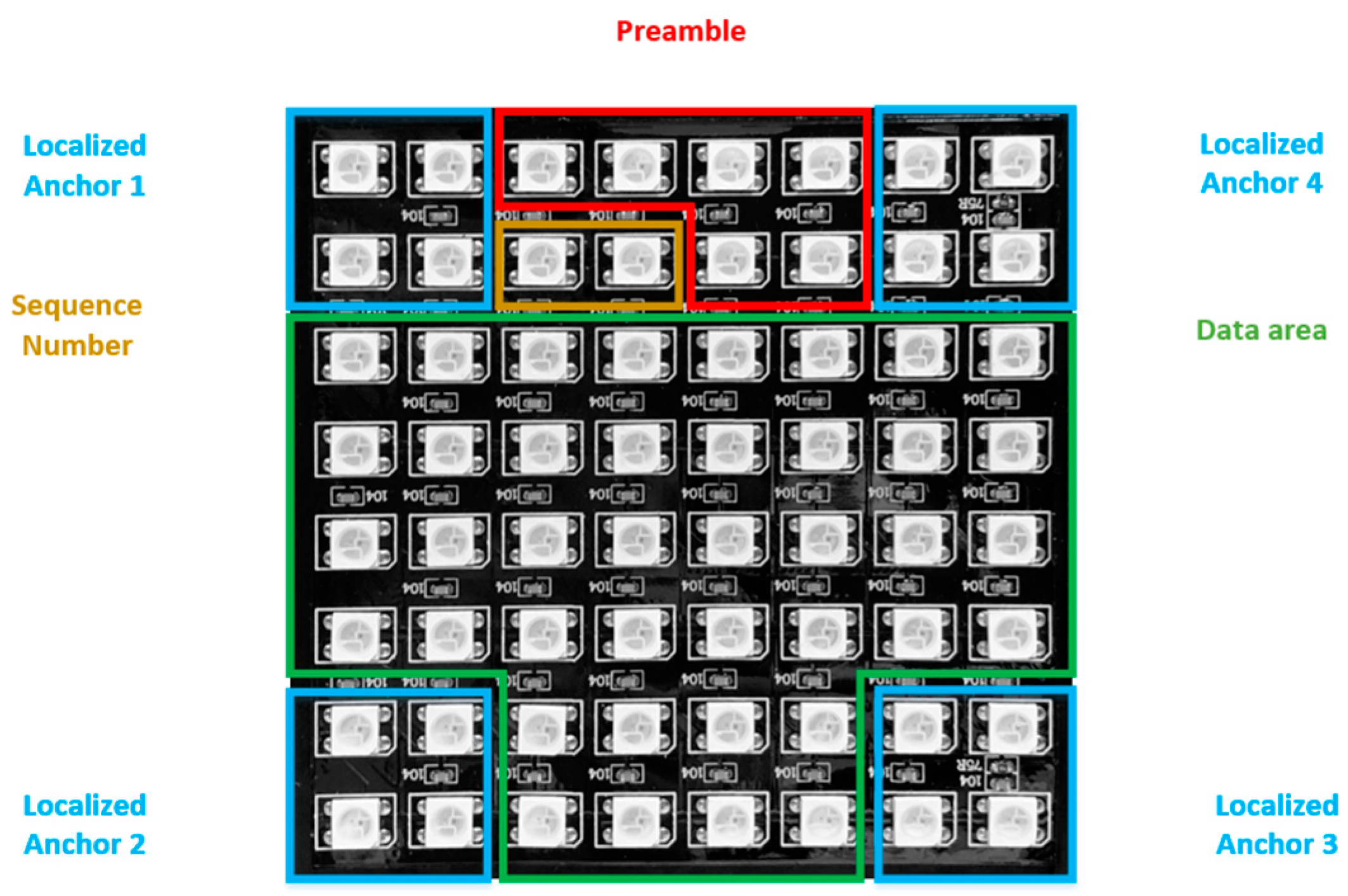
  • Frame rate variation support: Presently, it is still believed that the frame rate described in the specifications of global-shutter and rolling-shutter cameras are constant, for example, 60 or 500 fps. However, in reality, the frame rate can undergo variations and fluctuate during camera usage. This causes several difficulties in decoding data on the receiver side, as well as synchronizing data between the transmitter and receiver side of the OCC system. To determine whether a sub-data packet is dropped during the transmission and reception of data, we use the sequence number (SN) in each one.
  • Data merger algorithm: As part of the proposed methodology, we include an SN in every sub-packet to identify where it falls in the sequence. We can adjust the SN length to best optimize system performance according to the length of the data packet.
  • Detection of missing packets: Aiming to combine data packets from two successive images, we embed an SN in each packet. This SN facilitates the straightforward detection of missing packets by comparing the SNs in two consecutive images, assuming that the SN length is adequate for the task.
  • Mobility support: A 2D-MIMO data transmission method that transfers data using an LED array that has multiple individual LEDs arranged in a matrix, like 8 by 8 or 16 by 16. When LEDs move at a specific speed and distance, conventional algorithms, such as the ROI method, become more difficult to use for LED recognition because the images of the LED array in the camera often appear noisy and hazy. In the meantime, YOLO algorithms are well-known for being incredibly effective methods for real-time object detection, especially for objects with a high rate of motion, such as cars and people. Therefore, we implemented the YOLOv8 algorithm for our OCC systems to improve the performance of LED array detection in mobile scenarios.
  • Reducing BER: To reduce BER, we propose and apply a deep-learning decoder to improve data decoding by applying a deep-learning decoder model trained by the dataset we gathered manually under various conditions, particularly when the LED array moves at varying speeds. Meanwhile, the LED image captured by the camera is often blurred in a mobility environment, making it harder for traditional decoding techniques to distinguish between bits 0 and 1, which raises the BER of the modulation scheme.

3. System Architecture

The fundamental idea behind the OCC system is to utilize the intensity of optical signals for data transmission and reception. Accordingly, enhancing the system’s overall communication performance significantly depends on an efficient modulation scheme. The most common modulation scheme is OOK, which is amplitude-shift keying modulation in its most basic form. It transmits data using two signal states, ON and OFF, which represent bits “1” and “0”, respectively. This paper presents the details of the proposed LED array scheme that uses the OCC technique to be designed for IoT systems. The spatial frame format defined in our scheme makes it easy to use deep-learning algorithms at the receiver side for data decoding and detection based on the location of each LED in the LED array. The architecture of the OOK-MIMO transceiver is illustrated in Figure 1, with the operational details of the blocks expounded in Section 3.

3.1. Channel Coding

Channel coding is an essential part of many digital communication systems. It is most commonly used as a forward error control (FEC) mechanism, which is well known for its ability to identify and minimize bit errors in the digital domain. By using channel coding strategically on both the transmitter and receiver, the communication system’s overall reliability is increased. Channel coding appears as an encoding technique on the transmitter side, where additional bits are added to the raw data before they are modulated. By contrast, channel coding facilitates decoding at the receiver end. By using channel coding in a methodical manner, mistakes in the data that are received can be easily found and fixed, which increases the system’s resilience. To ensure customized and efficient error-control measures in the context of our experimental setup, the size of the LED matrix determined the best channel-coding scheme. In our works, Hamming (11/15) code was proposed to improve performance of OCC system.

3.2. Deep Learning for Tracking and Detecting LEDs

In the OCC system, the RoI algorithm is a widely used part. The majority of RoI methods involve real-time processing for object detection, utilizing both object-based and feature-based detection techniques [30]. In addition, deep-learning neural networks present a powerful technique in computer vision applications, encompassing tasks, such as object detection, image classification, object positioning, and image reproduction. You Only Look Once (YOLO) has emerged as a robust method in real-time object detection because YOLO algorithms process the entire image at once and predict bounding boxes, class probabilities, and confidence scores for those predictions simultaneously [31]. Because of this, YOLO algorithms are more suitable than RoI algorithms for real-time applications, particularly in IoT systems employing OCC techniques, where the transmitting devices could comprise LED arrays. As the transmitter side for data transmission in the proposed method, an 8 × 8 LED matrix, which consists of 64 individual LEDs that flash at high speed and can move, is utilized.
Presently, the YOLO architecture comprises eight distinct versions, ranging from YOLOv1 to YOLOv8. The choice of a specific version is contingent upon the objectives of application tasks, enabling the avoidance of unnecessary resource and cost expenditures during real-world deployment. Fundamentally, YOLO can be categorized into two primary versions: tiny and base. With a smaller parameter set and a more straightforward network architecture than the base version, the tiny version is more suited for embedded devices and mobile development, particularly IoT systems. In this paper, we propose the YOLOv8 model for LED tracking and detection, which is highly applicable to real-world IoT systems and takes mobility effects into account. The model is designed to address the limitations of high hardware demands, which in turn is a determining factor for practical deployment in IoT applications. As a streamlined iteration of YOLOv8, the YOLOv8-tiny model boasts fewer layers, a higher detection speed, compatibility with portable devices, and reduced GPU resource requirements for training.

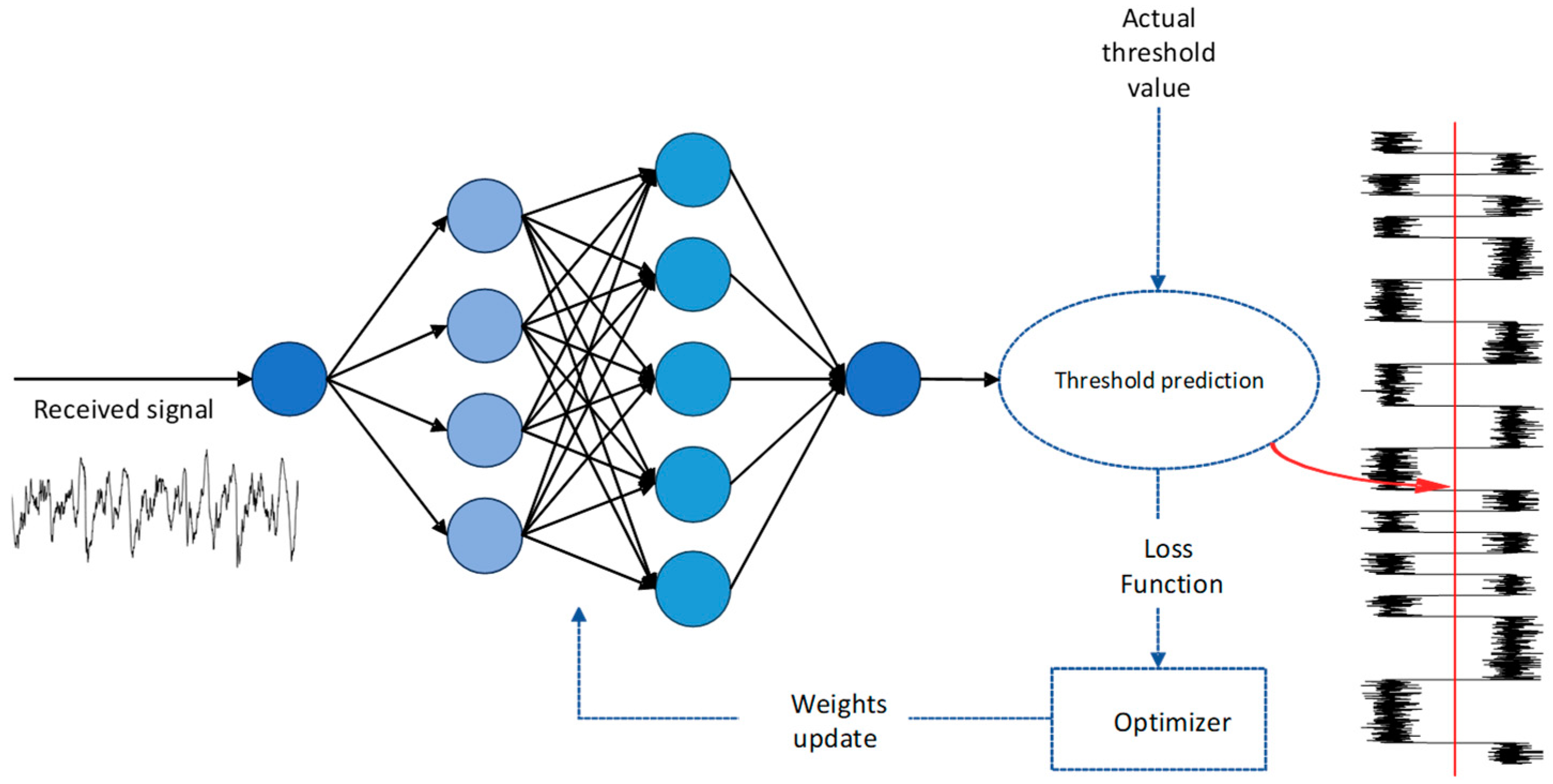
3.3. Deep Learning for Decoding Data

When the communication distance is extended, SNR values tend to diminish, posing challenges for the receiver in establishing a clear threshold between ON and OFF values. Addressing this concern, a matched filter method was previously proposed in [29] to optimize SNR values and extend the communication distance. However, in a mobility environment, the SNR is very harsh to decode data; therefore, we propose a neural network model that is trained by various datasets to increase our decoding performance.
After the LED is detected, the signals of all LED areas are converted from image form (parallel) to serial form for data decoding. The signal obtained after conversion is shown in Figure 2. The blur effect in OCC systems is generally caused by the relative movement of the transmitter and receiver. Consequently, the deployed system experiences inter-symbol interference, which significantly reduces system performance. In a mobile environment, identifying the preamble is crucial for decoding the signal, as only afterward can the remaining data segments be easily decoded. To simplify the decoding of the signal on the camera side of the system when deploying the system in a mobile environment, we implemented a deep-learning decoder to identify the preamble of each data packet. Using the RMSE metric, we calculated and evaluated the accuracy of the deep-learning decoder model to assess its performance. In 200 epochs, the system demonstrated high accuracy, which was reflected by the low value of error (<0.1) during the forecasting process.
After the images are recorded by the camera, utilizing the YOLO algorithm, we can determine the image area with the LED array and then adopt image-processing and coding techniques to decode data from the LED region. In particular, we extract OCC signals from the image format (parallel data format) to serial format (serial data stream) in the identified LED region using the down-sampling method, and we extract the 2D-MIMO signal using the center intensity point of the LEDs. The dataset (9000 data samples) for the deep-learning decoder was gathered using a variety of commercial camera types at varying distances (between 2 and 22 m) and under different circumstances, including mobility and rotation. We used a simple two-layered deep-learning neural network model to prevent the model from overfitting. After preamble detection, the threshold of the 2D-MIMO signal can be accurately identified when compared to traditional technology in a mobile environment. Six or more hidden layers would compromise the test dataset’s accuracy in the event of overfitting.

4. Implementation

4.1. Noise Modeling and Computation of Pixel per Bit to Spectral Noise Density

In CCD/CMOS cameras, the pixel noise can be roughly characterized using Equation (1), as outlined in [29]:
n N 0 , δ s 2
where s denotes the value of a pixel, δ s 2 = s × a × α + β, where a denotes the mark and space amplitude, and α and β are the fitting factors derived from experimental data. Our system implementation incorporated model-fitting coefficients obtained from experiments to enhance predictive accuracy. Further, Equation (2) was used to calculate the (energy-per-bit-to-noise-power-spectral-density ratio) Eb/N0 on the receiving side under the assumption that one symbol equals one bit:
P i x e l E b N 0 = E [ s 2 ] E [ n 2 ] a 2 × a × α × + β
where Eb denotes the bit energy, N 0 represents the noise density, s signifies a pixel value, Δ is the ratio of the camera exposure time to the bit interval Δ = ( T e x p o s u r e / T b i t ), and α and β are the parameters obtained through the fitting.

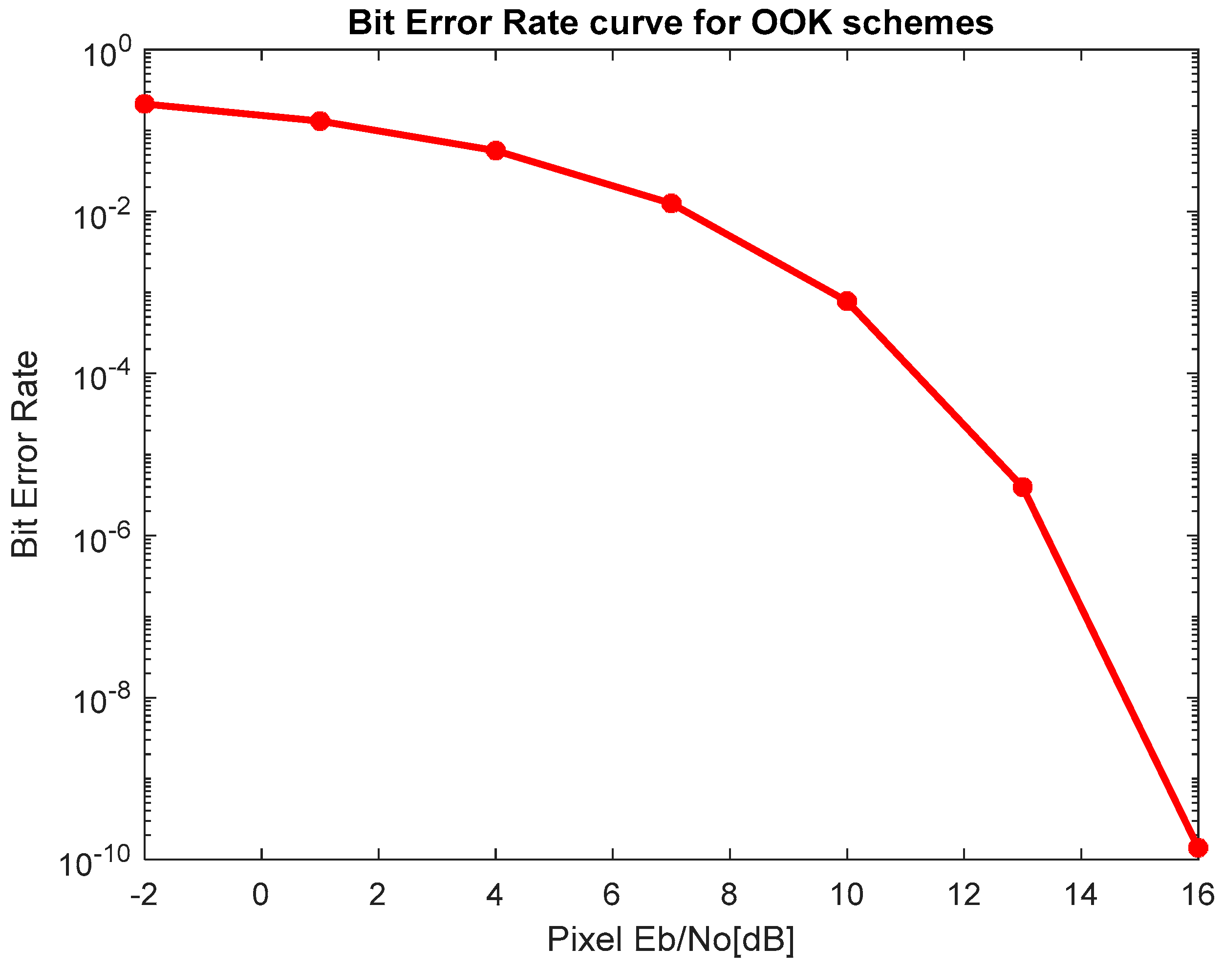
4.2. BER Estimation for Optical OOK Modulation

The calculation of the electrical amplitude of the received signal r t on the receiver side of the communication system is determined as follows:
r t = I t + i = + I t a i g t i T s y m b o l + n ( t )
where a i represents the magnitude of the i-th symbol, with a i taking values of either −1 or 1. t represents the time process. I ( t ) represents the amplitude of the signal. The probabilities for bit 0 and bit 1 are denoted as P 0 and P 1 , respectively. The function g(t) corresponds to a rectangular function, and the symbol duration is denoted by T s y m b o l . Equation (4) provides an expression for BER in the case where the channel model contains only additive white Gaussian noise (AWGN). AWGN is a basic noise model used in information theory to mimic the effect of many random processes that occur in nature. erfc represents the complementary error function.
P e = 1 2 e r f c ( E b 2 σ n 2 )
Because of the exclusive existence of the AWGN channel, the representation of the OOK signal for both bits 0 and 1 is as follows:
r t = n t , a i = 1   2 . I t + n t , a i = 1

4.3. Proposed Modulation Scheme

As illustrated in Figure 3, our system applies an LED array, which is formatted into a spatial frame to guarantee synchronization between the light source and camera during data transmission. The four external LED areas are delineated by blue squares, which are strategically designed for angle detection. Figure 4 shows BER curve for the optical OOK modulation. By detecting the four corners of the LED array, the positions of all LEDs are readily computed through perspective transformation. With the purpose of data transmission, our scheme utilizes 40 LEDs to encode data, as visually depicted in Figure 5. A distinctive feature of our approach involves the introduction of four position anchor components situated at the corners, as illustrated in Figure 5. Additionally, particular attention is paid to the location of corner 3 to support spinning on the decoder part. The training signal segment is made up of 16 LEDs that are labeled as position anchors. These LEDs use the zeros crossing technique to help the camera distinguish between the “on” and “off” states of each LED. Furthermore, preamble is added to every data frame so that the receiver can determine the commencement of the frame more easily.
Line coding and the deep-learning decoder technique were used to increase the SNR, which in turn increased the communication distance. Further, deep-learning algorithms were incorporated to aid in the detection of multiple LED arrays, particularly in the presence of mobility effects, aiming to boost the overall OCC system. Each captured image corresponds to a data packet and it makes data synchronization between the receiver and transmitter difficult in practice owing to the unstable frame per second (fps) of the camera. For example, if the camera parameter specified by the manufacturer is 30 fps, in reality, the frame rate per second may fluctuate above or below the 30 fps threshold. This must be taken into account and controlled to ensure the performance of the OCC system. Owning to the data packet rate on the transmitter side is almost constant, which makes undersampling and oversampling phenomena occur on the camera side. In the case that the data packet rate sent in 1 s is greater than the camera frame rate in 1 s, the undersampling phenomenon will occur, causing the camera to be unable to keep up with the data packets one by one in a sequence, resulting in missing data, which affects the system’s data transmission and reception. On the other hand, if the speed of the data packet sent in one second is lower than the frame rate of the camera in one second, oversampling occurs. The camera may capture a data packet two to three times, resulting in redundancy and duplicate data. To solve the two cases of oversampling and undersampling, we propose to use SN as the identifier for each data packet. This makes data decoding easier and achieves the highest accuracy. The camera parameters and implementation requirements determine the SN length that can be adjusted. Extended SN lengths are recommended in situations where the camera quality is low or the conditions are not ideal, which leads to a higher rate of packet loss. By contrast, the SN length shortens with a higher camera quality, which boosts system performance. In Figure 5, the SN length is 2 bits, and the preamble length is 6 bits. We can adjust the length of the SN and preamble depending on camera parameters and implementation requirements. The payload will be displayed in the data area with a length of 40 bits per frame, where the ON or OFF status of the LED represents either a 1 or 0 bit.

4.3.1. Oversampling

Oversampling occurs on the condition that the captured image rate per second of the receiving end is more than twice that of data transmission of the light source. In this case, each data packet will be captured by the receiving camera two, three, or even more times, which leads to data redundancy and difficulty in merging data. To address this problem, each data sub-packet (DS) has SN values appended to it, guaranteeing consistent payload and SN across DSs. By utilizing the SN, the receiving camera is able to identify compatible DSs and remove those that are unnecessary owing to oversampling. Accordingly, during the merging process, the receiving camera chooses packets with ascending SN values (m, m + 1, m + 2) to systematically remove duplicates.

4.3.2. Undersampling

Undersampling happens when the captured image rate per second of the receiving end is less than the data transmission rate of the light source. The packet merge function is confused in this instance because the DS is overlooked. It is simple to recover the entire missing payload by appending a specific SN value to every packet. Likewise, each DS derived from a certain data packet will be marked by the value of the SN of that data packet. This allows for the easy detection of lost data packets by comparing consecutive SN values to determine which data packets were missed. In addition, the amount of missed payloads is computed by accounting for the length of the SN. For example, the system can identify up to 15 missed payloads if the bit length of SN is 5. If two nearby payloads that are not adjacent to the SN value are detected by the system (e.g., m and m + 2), the missed payload m + 1 is realized.

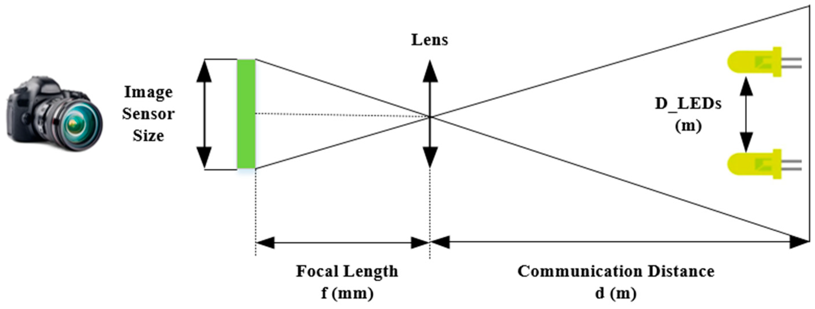
4.3.3. Communication Distance Calculation

Among the factors for evaluating the performance of an OCC system, communication distance is also a very important factor, in addition to BER and SNR. This is one of the factors that makes the difference between OCC systems and Li-Fi or VLC. By applying a deep-learning method on the receiver side for object tracking and detection, the proposed scheme can communicate and retrieve data from many different transmitters simultaneously. However, the distance calculation needs to be carefully considered to avoid light interference on the camera or excessive noise, causing the communication of the entire system to be affected when communicating with many transmitters simultaneously. To calculate the maximum distance needed for communication from the camera to the LED array, the following factors need to be considered: focal length of the camera, communication distance between the receiver and transmitter sides, and consecutive distance between two LEDs. The relationship between them is shown in Figure 6:
Equation (6) gives the relationship between the communication distance and focal length of the camera:
d [ m ] D _ L E D s [ m ] = f [ m m ] d _ L E D s [ m m ]
whereas f and d stand for the working distance and the focal length of the camera, respectively, D_LEDs represents the actual physical distance between two LEDs in a real-world experiment, and d_LEDs stands for the distance between these two LEDs as captured in the image. With Equation (6), one can determine the shortest path between two LEDs. This minimum distance between two LEDs within two pixels is determined by using RoIs based on the deep learning method and the Nyquist theorem. Equation (7) gives the formula for calculating the minimum distance between two LEDs:
D _ L E D s m = 2   ×   d [ mm ] f [ mm ] × h _ sensor _ image [ m ] N _ pixel _ image _ row
where the N_pixel_image indicates how many pixel rows there are in the image and h_sensor_image indicates the height of the sensor image in millimeters. With the working distance dependent on the transmitted light power, the theoretical distance is expressed as d [m], which simplifies the computation. When ambient noise lights have a higher power than the transmitter, interference occurs. Consequently, it becomes feasible to establish the maximum number of users by considering the real-world environment.

4.3.4. Implementation Results

Taking advantage of the 2D-MIMO scheme, we utilized commercial cameras to evaluate the proposed scheme. We conducted this experiment using a Microsoft global-shutter camera and a Point Gray rolling-shutter camera to evaluate system performance under frame-per-second fluctuations. On the receiver side, using a combination of deep-learning methods and image-processing techniques, data decoding is performed sequentially in steps from LED tracking and detection to missing data packet detection and data packet merging based on the SN value of each data packet. The quantized intensity profiles of the LED array images captured at a distance of 4 m and an exposure time of 300 s are shown in Figure 7. Depending on the conditions of the application, for example, the distance communication or mobility environment, these parameters can be changed. The setup of the proposed implementation is shown in Figure 8, and the webcam experiment results are shown in Figure 9. The transmitter side will be implemented with an LED matrix and controlled by Arduino with a 2D-MIMO encoder. In the receiver side, the Python 3.6 version was proposed to decode and for tracking the LED matrix. Table 1 displays the results of the implementation. Based on Table 1, we can see that with a 16 × 16 LED matrix, the data rate can achieve 15.360 kbps when it is 3.840 kbps with an 8 × 8 LED matrix with a velocity of 3 m/s. Then, to increase the data rate, we can change the version of the LED matrix.
We experimented with differing exposure times and communication distances using a Point Gray rolling shutter camera to determine the BER value of the OCC system. We measured the BER of these two approaches under the same distance and environmental conditions to have the best comparison between the deep-learning method and the conventional decoder. The comparative outcomes are shown in Figure 10 with an exposure time of 100 µs. At a distance of 10 m, we could achieve a BER of 10 3 with the deep-learning approach; by contrast, the BER value was only 10 2 with the conventional approach. Thus, with the deep-learning approach, we could enhance the performance of the OCC system under long distance and the mobility effect. Besides, channel coding plays an important role in implementing an OCC system when there is a lot of noise from the external environment, which directly affects the quality of data transmission between the receiver and transmitter. Applying channel coding to the system will help to reduce the number of bit errors and improve the transmission and reception distance at the same time. However, the trade-off between exposure time and signal noise needs to be carefully considered because of the close relationship between the communication bandwidth and exposure time. Table 1 presents the parameters of the proposed scheme. The proposed scheme was implemented with a LED matrix at a communication distance of 2 m in Supplementary Materials.

5. Conclusions

In this paper, for the OCC technique, we adopt an 8 × 8 LED array for data transmission to the OCC system. This 2D OOK-MIMO modulation scheme-based system is designed for IoT applications and supports the rotation effect using a special spatial frame format of the LED matrix. Specifically, we collect and transmit measurement data from the environment, such as temperature and humidity, utilizing an LED array based on 2D code. To control data decoding and the frame rate variation effect, the SN is used to control the order of data packets in multiple consecutive images and thus avoid missing data. We also evaluated the relationship among the communication distance, SNR value, and exposure time by measuring the SNR at several communication distances and with different exposure time values. The results show that the SNR rises with the exposure time, while the system bandwidth correspondingly falls. Therefore, choosing the exposure time needs to be carefully considered when deploying the system. Moreover, OCC performance can be improved with the YOLOv8 algorithm instead of the RoI algorithm considering the mobility environment. In addition, the deep-learning decoder also showed higher performance compared to the conventional algorithm. This was revealed by the BER performance of the 2D-MIMO scheme considering different distances (2–22 m) and a mobility of 3 m/s with a BER of 10 4 at a distance of 7 m.

Supplementary Materials

The following are available online at https://www.mdpi.com/article/10.3390/app14031003/s1. The supplementary material video shows the implementation of our proposed scheme at a distance of 2 m.

Author Contributions

All authors contributed to this paper: D.T.A.L. proposed the idea and implemented the methodology; D.T.A.L. and H.N. reviewed the work and edited the paper; H.N. performed all experiments; Y.M.J. supervised the work and provided funding support. All authors have read and agreed to the published version of the manuscript.

Funding

This research was supported by the Ministry of Science and ICT (MSIT), Korea, under the Information Technology Research Center (ITRC) support program (IITP-2018-0-01396) supervised by the Institute for Information and Communications Technology Promotion (IITP); this work was also supported by a National Research Foundation of Korea (NRF) grant funded by the Korean government (MSIT) (No. 2022R1A2C1007884).

Institutional Review Board Statement

Not applicable.

Informed Consent Statement

Not applicable.

Data Availability Statement

The data presented in this study are available on request from the corresponding author. The data are not publicly available due to project requirements.

Conflicts of Interest

The authors declare no conflicts of interest.

References

  1. Lee, Y.L.; Qin, D.; Wang, L.-C.; Sim, G.H. 6G Massive Radio Access Networks: Key Applications, Requirements and Challenges. IEEE Open J. Veh. Technol. 2021, 2, 54–66. [Google Scholar] [CrossRef]
  2. Chettri, L.; Bera, R. A Comprehensive Survey on Internet of Things (IoT) toward 5G Wireless Systems. IEEE Internet Things J. 2020, 7, 16–32. [Google Scholar] [CrossRef]
  3. Seferagić, A.; Famaey, J.; De Poorter, E.; Hoebeke, J. Survey on Wireless Technology Trade-Offs for the Industrial Internet of Things. Sensors 2020, 20, 488. [Google Scholar] [CrossRef] [PubMed]
  4. Okechukwu, C.E. Effects of Radiofrequency Electromagnetic Field Exposure on Neurophysiology. Adv. Hum. Biol. 2020, 10, 6–10. [Google Scholar] [CrossRef]
  5. Nguyen, H.; Nguyen, V.; Nguyen, C.; Bui, V.; Jang, Y. Design and Implementation of 2D MIMO-Based Optical Camera Communication Using a Light-Emitting Diode Array for Long-Range Monitoring System. Sensors 2021, 21, 3023. [Google Scholar] [CrossRef] [PubMed]
  6. Saeed, N.; Guo, S.; Park, K.-H.; Al-Naffouri, T.Y.; Alouini, M.-S. Optical camera communications: Survey, use cases, challenges, and future trends. Phys. Commun. 2019, 37, 100900. [Google Scholar] [CrossRef]
  7. Boulogeorgos, A.-A.A.; Trevlakis, S.E.; Chatzidiamantis, N.D. Optical Wireless Communications for In-Body and Transdermal Biomedical Applications. IEEE Commun. Mag. 2021, 59, 119–125. [Google Scholar] [CrossRef]
  8. Karunatilaka, D.; Zafar, F.; Kalavally, V.; Parthiban, R. LED Based Indoor Visible Light Communications: State of the Art. IEEE Commun. Surv. Tutor. 2015, 17, 1649–1678. [Google Scholar] [CrossRef]
  9. IEEE Std 802.15.7-2011; IEEE Standard for Local and Metropolitan Area Networks—Part 15.7: Short-Range Wireless Optical Communication Using Visible Light. IEEE-SA: Piscataway, NJ, USA, 2011.
  10. IEEE Std 802.15.7-2018; IEEE Standard for Local and Metropolitan Area Networks—Part 15.7: Short-Range Optical Wireless Communications. IEEE-SA: Piscataway, NJ, USA, 2018.
  11. Rahimpour, S.; Kiyani, M.; Hodges, S.E.; Turner, D.A. Deep brain stimulation and electromagnetic interference. Clin. Neurol. Neurosurg. 2021, 203, 106577. [Google Scholar] [CrossRef]
  12. Ong, Z.; Rachim, V.P.; Chung, W.-Y. Novel Electromagnetic-Interference-Free Indoor Environment Monitoring System by Mobile Camera-Image-Sensor-Based VLC. IEEE Photonics J. 2017, 9, 1–11. [Google Scholar] [CrossRef]
  13. Haas, H.; Yin, L.; Wang, Y.; Chen, C. What is LiFi? J. Light. Technol. 2016, 34, 1533–1544. [Google Scholar] [CrossRef]
  14. Sheoran, S.; Garg, P.; Sharma, P.K. Location tracking for indoor VLC systems using intelligent photodiode receiver. IET Commun. 2018, 12, 1589–1594. [Google Scholar] [CrossRef]
  15. Haas, H.; Yin, L.; Chen, C.; Videv, S.; Parol, D.; Poves, E.; Alshaer, H.; Islim, M.S. Introduction to indoor networking concepts and challenges in LiFi. J. Opt. Commun. Netw. 2020, 12, A190–A203. [Google Scholar] [CrossRef]
  16. Khalighi, M.A.; Uysal, M. Survey on Free Space Optical Communication: A Communication Theory Perspective. IEEE Commun. Surv. Tutor. 2014, 16, 2231–2258. [Google Scholar] [CrossRef]
  17. Ali, A.Y.; Zhang, Z.; Zong, B. Pulse position and shape modulation for visible light communication system. In Proceedings of the 2014 International Conference on Electromagnetics in Advanced Applications (ICEAA), Palm Beach, Aruba, 3–8 August 2014; pp. 546–549. [Google Scholar] [CrossRef]
  18. Videv, S.; Haas, H. Practical space shift keying VLC system. In Proceedings of the 2014 IEEE Wireless Communications and Networking Conference (WCNC), Istanbul, Turkey, 6–9 April 2014; pp. 405–409. [Google Scholar] [CrossRef]
  19. Deng, P.; Kavehrad, M. Real-time software-defined single-carrier QAM MIMO visible light communication system. In Proceedings of the 2016 Integrated Communications Navigation and Surveillance (ICNS), Herndon, VA, USA, 19–21 April 2016; pp. 5A3-1–5A3-11. [Google Scholar] [CrossRef]
  20. Cai, H.-B.; Zhang, J.; Zhu, Y.-J.; Zhang, J.-K.; Yang, X. Optimal Constellation Design for Indoor 2 × 2 MIMO Visible Light Communications. IEEE Commun. Lett. 2016, 20, 264–267. [Google Scholar] [CrossRef]
  21. Nguyen, V.L.; Tran, D.H.; Nguyen, H.; Jang, Y.M. An Experimental Demonstration of MIMO C-OOK Scheme Based on Deep Learning for Optical Camera Communication System. Appl. Sci. 2022, 12, 6935. [Google Scholar] [CrossRef]
  22. Nguyen, H.; Thieu, M.D.; Pham, T.L.; Nguyen, H.; Jang, Y.M. The impact of camera parameters on optical camera communication. In Proceedings of the International Conference on Artificial Intelligence in Information and Communication (ICAIIC), Jeju Island, Republic of Korea, 11–13 February 2019. [Google Scholar]
  23. Ayyash, M.; Elgala, H.; Khreishah, A.; Jungnickel, V.; Little, T.; Shao, S.; Rahaim, M.; Schulz, D.; Hilt, J.; Freund, R. Coexistence of WiFi and LiFi toward 5G: Concepts, opportunities, and challenges. IEEE Commun. Mag. 2016, 54, 64–71. [Google Scholar] [CrossRef]
  24. Huang, W.; Tian, P.; Xu, Z. Design and implementation of a real-time CIM-MIMO optical camera communication system. Opt. Express 2016, 24, 24567–24579. [Google Scholar] [CrossRef]
  25. Teli, S.R.; Matus, V.; Zvanovec, S.; Perez-Jimenez, R.; Vitek, S.; Ghassemlooy, Z. Optical Camera Communications for IoT–Rolling-Shutter Based MIMO Scheme with Grouped LED Array Transmitter. Sensors 2020, 20, 3361. [Google Scholar] [CrossRef]
  26. Isa, I.S.; Rosli, M.S.A.; Yusof, U.K.; Maruzuki, M.I.F.; Sulaiman, S.N. Optimizing the Hyperparameter Tuning of YOLOv5 for Underwater Detection. IEEE Access 2022, 10, 52818–52831. [Google Scholar] [CrossRef]
  27. Guan, W.; Li, J.; Wen, S.; Zhang, X.; Ye, Y.; Zheng, J.; Jiang, J. The Detection and Recognition of RGB-LED-ID Based on Visible Light Communication using Convolutional Neural Network. Appl. Sci. 2019, 9, 1400. [Google Scholar] [CrossRef]
  28. Hsieh, C.-H.; Lin, D.-C.; Wang, C.-J.; Chen, Z.-T.; Liaw, J.-J. Real-Time Car Detection and Driving Safety Alarm System WithGoogle Tensorflow Object Detection API. In Proceedings of the 2019 International Conference on Machine Learning and Cybernetics (ICMLC), Kobe, Japan, 7–10 July 2019; pp. 1–4. [Google Scholar] [CrossRef]
  29. Nguyen, V.H.; Thieu, M.D.; Nguyen, H.; Jang, Y.M. Design and Implementation of the MIMO–COOK Scheme Using an Image Sensor for Long-Range Communication. Sensors 2020, 20, 2258. [Google Scholar] [CrossRef]
  30. Lin, H.; Si, J.; Abousleman, G.P. Region-of-interest detection and its application to image segmentation and compression. In Proceedings of the 2007 International Conference on Integration of Knowledge Intensive Multi-Agent Systems, Waltham, MA, USA, 30 April–3 May 2007. [Google Scholar]
  31. Diwan, T.; Anirudh, G.; Tembhurne, J.V. Object detection using YOLO: Challenges, architectural successors, datasets and applications. Multimed. Tools Appl. 2023, 82, 9243–9275. [Google Scholar] [CrossRef]
Figure 1. Reference architecture of 2D–MIMO technique based on a deep-learning neural network.
Applsci 14 01003 g001
Figure 2. Implementation results of the 2D MIMO scheme for an 8 × 8 LED matrix.
Applsci 14 01003 g002
Figure 3. System architecture of the deep-learning decoder for threshold prediction.
Applsci 14 01003 g003
Figure 4. BER curve for the optical OOK modulation.
Applsci 14 01003 g004
Figure 5. Spatial frame format in an LED array.
Applsci 14 01003 g005
Figure 6. Relationship between the focal length and communication distance.
Applsci 14 01003 g006
Figure 7. Quantized intensity profile of the LED matrix at 4 m with an exposure time of 300 µs.
Applsci 14 01003 g007
Figure 8. Setup scenario of proposed scheme with the LED matrix and webcam.
Applsci 14 01003 g008
Figure 9. Rx interface.
Applsci 14 01003 g009
Figure 10. BER performance of proposed system for an 8 × 8 LED array with different distances considering a velocity of 3 m/s with exposure time of 100 µs.
Applsci 14 01003 g010
Table 1. Characteristic parameters of the proposed scheme.
Transmitter Side
LED array size8 × 816 × 16
The number of LEDs64256
Power supply5 V, 2 W5 V, 5 W
FECHamming (11/15)
Packet rate60 packet/s
Receiver side
CameraPoint Grey rolling-shutter camera
Throughput
Uncode bit rate3.840 kbps15.360 kbps
Code bit rate2.816 kbps11.264 kbps
Disclaimer/Publisher’s Note: The statements, opinions and data contained in all publications are solely those of the individual author(s) and contributor(s) and not of MDPI and/or the editor(s). MDPI and/or the editor(s) disclaim responsibility for any injury to people or property resulting from any ideas, methods, instructions or products referred to in the content.

