Article

Design and Development of Rice Pot-Seedling Transplanting Machinery Based on a Non-Circular Gear Mechanism

1
College of Agricultural Engineering, Jiangsu University, Zhenjiang 212013, China
2
School of Engineering, Northeast Agricultural University, Harbin 150030, China
*
Author to whom correspondence should be addressed.
Appl. Sci. 2024, 14(3), 1027; https://doi.org/10.3390/app14031027
Submission received: 3 December 2023 / Revised: 21 January 2024 / Accepted: 23 January 2024 / Published: 25 January 2024
(This article belongs to the Section Agricultural Science and Technology)

Abstract

:
Transplanting rice pot seedlings without damaging the roots, which promotes early tillering, is an effective measure to enhance rice yield and quality. This study aimed to obtain the mechanized-transplanting trajectory and attitude of rice pot seedlings by utilizing non-circular planetary-gear trains, focusing on the three key actions of rice pot-seedling transplanting: seedling picking, conveying, and planting. A lightweight and simplified rice pot-seedling transplanting machinery was designed, referring to the motion characteristics of artificially transplanting rice pot seedlings by first pulling them out and then planting them. Key technologies such as non-circular gear trains, the rice seedling supply system, the transmission system, and the rice seedling-picking device were studied, and their key components were designed and manufactured, resulting in the creation of two physical model machines: an ordinary ride type and a high-speed type. The seedling-picking test and field-transplanting test showed that the rice pot-seedling transplanting mechanism can accomplish the rice pot-seedling picking, rice conveying, and planting actions. The designed operation efficiency yielded a planting-depth qualification rate of over 92%, a seedling injury rate of less than 1.2%, and a missed-transplanting rate of less than 2%.

1. Introduction

Rice is the main crop in the world, and the general population in the world takes rice as a staple food, so research on rice mechanization and yield-increase technology is of great significance. Rice transplanting is a popular method of planting that can be carried out in two ways: blanket-seedling transplanting and pot-seedling transplanting. Figure 1 illustrates the process of picking seedlings. With blanket-seedling transplanting, the seedlings are picked by cutting off the root system connected to them. However, this method results in a longer survival stage for the slow seedling after transplanting. On the other hand, pot-seedling transplanting involves the use of independent substrates for each hole of the rice pot seedlings. This is beneficial because it promotes the cultivation of strong seedlings without damaging the roots, leading to early tillering. As a result, this method can effectively improve the yield and quality of rice. Although the agronomic technique of rice pot-seedling transplanting has been proposed for many years, the trajectory and attitude of rice pot-seedling transplanting are complex, and the problem of mechanism realization is difficult to solve. As such, mechanized rice transplanting still primarily relies on blanket-seedling transplanting. Currently, research on rice pot-seedling transplanting machines primarily focuses on kinematic analysis, parameter optimization, and virtual simulation. However, there is little emphasis on the design and manufacturing of the entire machine. Japan ISEKI & Co., Ltd. has created a push-out rice pot-seedling transplanting machine [1], which utilizes four sets of mechanisms to push out, flip, convey, and plant seedlings. However, the machine’s complex mechanism and limited promotion and application region have hindered its widespread use. Amico Machinery Equipment Co., Ltd. has also introduced Japanese technology [2] to produce the 2ZB-6A ride-type rice pot-seedling transplanting machine. However, the high cost of the hard seedling hole-tray used by the equipment has restricted its promotion and application. K. Rahul et al. [3] present a complete mechatronic approach in designing. They developed a robotic arm to handle paper pot seedlings in a transplanter for the purpose of including automation and possibly reducing the number of heavy mechanical components in pot-seedlings transplanters by utilizing microcontrollers and embedded systems. M.S. Imran et al. [4] used a linkage mechanism to design a small rice transplanter, especially for rice-intensive production, that adopts a ground-wheel drive, a simple structure, and low production cost. It was suitable for semi-automatic transplanting agronomy in Malaysia. M.E. Felezi et al. [5] used a multi-objective uniform-diversity genetic algorithm to optimize and synthesize the four-link rice-transplanting mechanism. They also proposed an optimal configuration of the transplanting mechanism to meet the requirements of different transplanting depths and space. Ted S. Kornecki et al. [6] developed a no-till vegetable transplanter powered by a walk-behind tractor to reduce heavy physical labor, which is often required in small-scale farming operations.
Scholars from China have extensively studied the kinematics and dynamics of transplanting mechanisms. Kang Xue [7] et al. established a dynamic model of the mechanism of the rice–soil coupling system by a computational fluid dynamics method and comprehensively analyzed the rice-transplanting process. The results showed that the impact load during rice transplanting was the main cause of stem damage. The base of the stem was the vulnerable part of the stem. The maximum workload of the seedling-picking needle was significantly affected by the root-system shape and soil-bonding strength of the rice seedlings. Tong et al. [8] designed a seedling-picking mechanism with a planetary-gear train based on the key attitude points of seedling picking. The motion law of the picking arm was constrained by a two-stage non-circular gear transmission, and the parameter reverse design was completed according to the ideal trajectory. Yu Gaohong et al. [9] proposed an inserting-pot-type mechanism for transplanting rice seedlings, which utilizes an incomplete non-circular gear planetary-gear train to achieve the desired trajectory and attitude. Similarly, Sun Liang et al. [10] designed a mechanism for transplanting rice seedlings utilizing a non-circular planetary seven-gear train system. The two independent non-circular gear pairs are responsible for driving two transplanting arms to achieve a specific trajectory and attitude. Zhou Yongqing et al. [11], on the other hand, established a parametric kinematics model of the transplanting mechanism based on the elliptical planetary-gear train, with the aim of obtaining the seedling-picking needle-tip trajectory that meets the transplanting requirements of super rice. In order to optimize the structural parameters of the elliptical planetary-gear-train transplanting mechanism, orthogonal tests were conducted, which showed a better transplantation effect. In order to further improve the planting efficiency of the high-speed automatic transplanter for vegetable plug seedlings, Wang Lei et al. [12] proposed a three-arm gear-train planting mechanism, and an approximate multi-pose motion-synthesis method based on a genetic algorithm (GA) was introduced. However, the gear transmission is complex, and the accuracy of picking seedlings is poor. Finally, Yao Yafang et al. [13] designed a rice seedling-box system that meets the requirements of a wide–narrow-row high-speed rice transplanter with adjustable row spacing. After experimental verification, it was found that the rice seedling-box system was stable and could meet the working requirements of an adjustable wide–narrow-row rice transplanter. Zhao Xiong et al. [14] took the non-circular planetary-gear-train transplanting mechanism as the rod group, combined it with the gear-train system for analysis, and provided three precise points of position and attitude for the transplanting trajectory. They obtained the rod-group parameter solution domain and entered the trajectory shape-control point to design the ideal transplanting trajectory; then, they obtained the transmission-ratio curve and the non-circular gear-joint curve, selecting the appropriate rod-group parameter-design mechanism model in the solution domain. Li et al. [15] have developed a four-claw type mechanism for pot-seedling-taking using incomplete gears. This mechanism has been optimized using the PSO-SA algorithm to obtain the optimal parameters, resulting in a higher success rate for picking seedlings. It is worth noting that the research on key technologies related to rice pot-seedling transplanting machines is still in the experimental phase and has yet been widely applied.
This study involved designing a transplanting mechanism for rice pot seedlings based on their anthropomorphic transplanting trajectory and attitude. The focus was on studying key technologies such as the rice seedling-supply system and the transmission system. Two model machines were developed; one an ordinary ride type and the other a high-speed type. These models were tested and demonstrated in various provinces including Jiangsu, Heilongjiang, Hubei, Jilin, and Hainan. The field-transplanting effect met the agronomic requirements of rice pot-seedling transplanting.

2. Working Principle and Posture Requirements

2.1. Working Principle and Attitude Requirements

The proposed mechanism for transplanting rotated rice pot seedlings in this project is depicted in Figure 2, with two rotary transplanting mechanisms symmetrically installed on either side of the transmission box. To illustrate the working principle of one of the transplanting mechanisms, consider the following example. Power is input via the transmission shaft (1) into the transmission box (2). The transmission bevel gear (3) is fixed to the sun shaft (4), through which the power is transmitted via the bevel-gear transmission. The non-circular gear train, consisting of five non-circular gears, is fixed to the sun shaft (4) and rotates along with it. Among these gears, the sun gear (6) and flange (5) are fixed by teeth and remain relatively stationary to the transmission box (2), while the intermediate gears ((9), (13)) are fixed to the intermediate shafts ((10), (12)) and are engaged with the sun gear. The intermediate gear ((9), (13)) is the center of the relatively rotating non-circular gear system on the intermediate shaft ((10), (12)). The planetary gear ((15), (7)) is fixed to planetary shaft ((14), (8)) and rotates while engaging with the intermediate gear. In the transplanting mechanism, the planetary carrier serves as the driving part. The non-circular gear system features a planetary shaft ((14), (8)) that protrudes from one end, while a transplanting arm ((16), (11)) is fixed to the other. As the non-circular gear system rotates with the sun shaft (4), the non-circular gears engage and rotate with each other. The gearbox facilitates a uniform circular motion for the transplanting arm ((16), (11)), while the planetary shaft enables the non-circular gear system to rotate at an equal speed. These two movements work together to create a complex “8”-type trajectory (17) and attitude for the transplanting arm ((16), (11)). By optimizing the non-circular gear parameters and structural parameters, the transplanting arm can achieve the characteristic trajectory and attitude required for rice pot transplanting, successfully performing the three actions of rice picking, conveying, and planting.
The transplanting arm is a crucial component of the transplanting mechanism, being directly responsible for picking and pushing the rice seedlings [16]. Figure 3 illustrates the structure of the transplanting arm, which consists of a fixed cam (9) on the gearbox and a transplanting arm (7) on the planetary shaft. During operation, the transplanting arm (7) rotates at an unequal speed relative to the cam (9). One end of the shifting fork (8), which is connected to the transplanting arm (7), interacts with the cam, while the other end drives the pusher rod (4) back and forth in a linear motion relative to the transplanting arm (7) through the spring seat (5). The pusher rod (4) is attached to the U-shaped clamp block (2) and pusher block (1). The two cylindrical rods of the U-shaped clamp block (2) are located outside of the two clamp slices (3), which are fixed on the transplanting arm (7). In the initial mounting position, the two clamp slices (3) remain open. As the shifting fork (8) rotates by lifting the cam (9), it retracts the pusher rod (4) and causes the U-shaped clamp block (2) to squeeze the two clamp slices (3) on the outside, firmly gripping the seedling. The two clamping flakes (3) are kept tightly closed and are followed by the movement of the transplanting-arm parts to the pushing position to complete the seedling-conveying process. When the transplanting arm moves to the position of the push seedling, one end of the shifting fork (8) moves to the return of the cam (9). The push rod (4) is quickly pushed forward by the action of the spring (6). The U-shaped clamp block (2) is disengaged from the clamp slices (3). The two clamp slices (3) open through the action of their own elasticity and release the seedlings. At the same time, the front end of the pusher block (1) fixed to the push rod (4) acts on the nutrient soil substrate to push the seedlings into the soil to complete the planting action. The fork (8) is then reset through the cam (9) in preparation for the next seedling-clamping action.

2.2. Picking-Type Trajectory and Attitude

The process of manually transplanting rice pot seedlings can be divided into three stages: picking the seedlings, conveying them, and planting them. After manually picking out the seedlings, we have identified the motion characteristics of transplanting and conclude that the mechanized transplanting of rice pot seedlings needs to adhere to a series of trajectory and attitude constraints, as shown in Figure 4: (1) When picking the seedlings, the transplanting arm must avoid picking them up from below but, instead, pick them up from the stems; (2) The transplanting arm should move at a low speed to the picking position, and the seedling-clamping device should quickly and accurately pick up the seedlings; (3) The picking process should follow the growth direction of the seedlings without causing any significant changes; (4) The conveying process should ensure that the transplanting arm and the picked seedlings do not interfere with the seedling box, and the seedlings should be rotated to an upright state; (5) The seedling angle should meet the putting angle and clamping requirements of the pot seedlings, preventing them from falling off from the seedling tray; (6) The seedling-pushing angle and the angle difference should comply with the requirements of planting uprightness; (7) To avoid not bringing back seedlings after planting, fast, accurate, and effective seedling pushing should be achieved; (8) To avoid soil stirring, the transplanting mechanism should be kept at a certain distance from the ground; (9) To prevent the phenomenon of a planting “bridge”, the trajectory should meet a certain height requirement.
In this study, information on various characteristics was abstracted, including the trajectory loop, picking height, seedling-picking angle, seedling-pushing angle, trajectory curvature, trajectory height, and other relevant information. Based on the agronomic requirements for transplanting rice pot seedlings, certain digital requirements were proposed for the transplanting trajectory and attitude. These requirements include (1) ensuring that the transplanting arms do not interfere with each other during the working process; (2) ensuring that the seedling-picking angle (the position of the transplanting arm when taking the seedlings) is within the range of −5° and 15°; (3) ensuring that the seedling-pushing angle (the position of the transplanting arm during planting) is within the range of 45° and 65°; (4) ensuring that the angle difference (the variation in the attitude of the transplanting arm during the conveying stage) is within the range of 50° and 60°; (5) ensuring that the height at which seedlings are picked is greater than 25 mm; (6) ensuring that the seedling-picking swing angle is less than 5° (the variation in the attitude of the transplanting arm in the picking stage); (7) ensuring that the transplanting arm does not push the seedlings (the trajectory does not collide with the stems of the seedlings after planting); (8) ensuring that during the conveying process, the seedlings and the seedling box do not interfere; (9) ensuring that the distance between the gearbox and the ground is greater than 25 mm (to prevent the transplanting mechanism from stirring the soil); and (10) ensuring that the trajectory height is greater than 250 mm (the trajectory should move forward along the rear of the seedlings around the top of the seedlings to avoid a “bridge” when transplanting large seedlings).

2.3. Kinematic Model of the Non-Circular-Gear Transplanting Mechanism

The schematic diagram of the non-circular-gear transplanting mechanism described in this paper is shown in Figure 5, wherein the pitch-curve shape of the non-circular sun gear and non-circular planetary gear is the same, the curve shape of the two intermediate-gear pitch curves is the same, and the structure of the two planting arms is the same and symmetrically installed. By establishing the kinematic model of the mechanism, the vector equation of motion at the end of the planting arm was derived, and the non-circular gear-pair transmission-ratio curve was optimized to obtain the anthropomorphic rice-transplanting trajectory.
Taking the side of the non-circular-gear transplanting mechanism as an example, the coordinate is established with the non-circular sun-gear rotation center O as the origin, as shown in Figure 6. The center of rotation of the intermediate gear is O 1 , the center of rotation of the non-circular planetary gear is O 2 , the planetary carrier O O 1 is regarded as the vector R 1 , the planetary carrier O 1 O 2 is regarded as the vector R 2 , and the planting arm is regarded as the vector R 3 ; then, the following vector relation can be obtained:
R 1 = a e j φ 1 ( t )
R 2 = a e j φ 2 ( t )
R 3 = l e j φ 3 ( t )
F = R 1 + R 2 + R 3
In the formula, φ 1 ( t ) is the angle of vector R 1 (planet carrier O O 1 ), φ 2 ( t ) is the angle of vector R 2 (planet carrier O 1 O 2 ), φ 3 ( t ) is the angle of vector R 3 (planting arm), a is the center distance of the gear, and l is the distance from the center of rotation of the non-circular planetary gear to the end of the planting arm. Expanding the above equation according to Euler’s formula:
R 1 = a cos φ 1 ( t ) + j a sin φ 1 ( t )
R 2 = a cos φ 2 ( t ) + j a sin φ 2 ( t )
R 3 = l cos φ 3 ( t ) + j l sin φ 3 ( t )
F = a cos φ 1 ( t ) + a cos φ 2 ( t ) + l cos φ 3 ( t ) + j ( a sin φ 1 ( t ) + a sin φ 2 ( t ) + l sin φ 3 ( t ) )
The angle of the planting arm relative to the planetary carrier is
β ( t ) = 0 ( ω 2 ω 1 ) t i ( θ ) d θ
In the formula, i ( θ ) is the transmission ratio between the non-circular sun gear and the intermediate gear, ω 1 is the speed of the non-circular sun gear, ω 2 is the speed of the planetary carrier, and the absolute rotation angle of the planting arm can be obtained from Equation (9):
φ 3 ( t ) = φ 1 ( t ) + β ( t )
The angle of the vector R 2 (planet carrier O 1 O 2 ):
φ 2 ( t ) = φ 1 ( t ) α
In the formula, α is the corner angle of the planetary carrier ( α = π O O 1 O 2 ) , and the vector equation F of the end of the planting arm and the vector equation R 3 of the planting arm can be obtained from Equations (8), (10), and (11):
F = a cos φ 1 ( t ) + a cos ( φ 1 ( t ) α ) + l cos ( φ 1 ( t ) + β ( t ) ) + j ( a sin φ 1 ( t ) + a sin ( φ 1 ( t ) α ) + l sin ( φ 1 ( t ) + β ( t ) ) )
R 3 = l cos ( φ 1 ( t ) α ) + j l sin ( φ 1 ( t ) α )
In the formula, φ 1 ( t ) = ω 2 t . Based on the vector kinematics model of the non-circular-gear transplanting mechanism, a visual optimization-design software was developed with the help of the numerical programming platform. The mechanism was optimized through the visualization software VB6.0, so that the end-motion pose met the requirements of anthropomorphic manual transplanting.

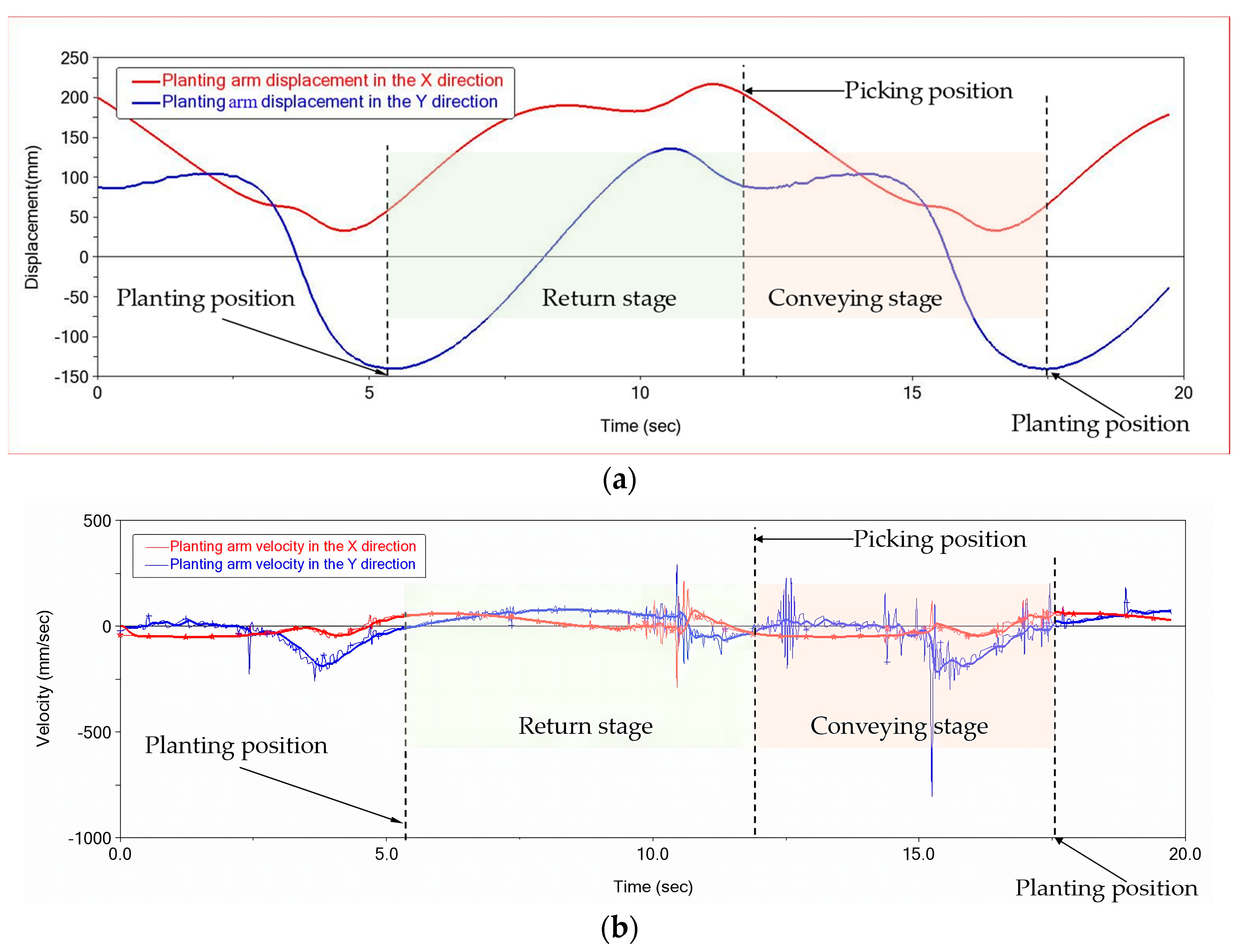
3. Description of Mechanism Parameters and the Work Cycle

Parameter optimization of the rice seedling-transplanting mechanism is a multimodal optimization problem with strong coupling. In this study, based on the kinematic model of the transplanting mechanism of rice pot seedlings, a visual parameter-optimization software (V1.0) for the transplanting mechanism was developed. The software controls the shape of the mechanism through parameters, changes the shape of the mechanism in real time by changing the parameters, and observes the end-motion trajectory of the mechanism and the transmission-ratio curve of non-circular gears in real time. The software includes a custom menu bar, a graphic-display area, a parameter-control area and a result-display area. The custom menu bar can save and open the mechanism parameters and can save the mechanism diagram; the graphic-display area can display the relative motion and absolute motion of the mechanism relative to the ground in real time and can also observe the initial installation position of the mechanism; and the result-display area can numerically calculate the agronomic objectives of rice transplanting, including the seedling-picking angle, seedling-pushing angle, trajectory height, planting-arm interference, hole width, and minimum gear modulus.
The transplanting mechanism for picking-type rice pot seedlings was optimized and designed, taking into account the digital requirements for transplanting trajectory and attitude. A set of the mechanism parameters that meet the requirements of transplanting trajectory and attitude were obtained: r1 = 21 mm, θ1 = 20°, r2 = 28 mm, θ2 = 45°, r3 = 50 mm, θ3 = 76°, r4 = 49 mm, θ4 = 105°, r5 = 58 mm, θ5 = 132°, r6 = 47 mm, θ6 = 165°, r7 = 18 mm, θ7 = 195°, r8 = 12 mm, θ8 = 225°, r9 = 28 mm, θ9 = 255°, r10 = 60 mm, θ10 = 285°, r11 = 48 mm, θ11 = 316°, r12 = 24 mm, θ12 = 345°, φ0 = 86°, α0 = −53°, β0 = −29°, S = 150 mm, H0 = 65 mm. ri represents the radius of the non-circular-gear pitch curve that controls the vertex of the polygon; θi represents the pole angle at which the non-circular-gear pitch curve controls the vertex of the polygon; φ0 indicates the initial assembly angle of the planetary carrier (gearbox); α0 indicates the corner angle of the planetary carrier (gearbox); β0 indicates the initial assembly angle of the transplanting arm relative to the planetary gear; S represents the distance from the center of rotation of the planetary gear to the end of the clamp slice; and H0 represents the vertical distance from the center of rotation of the planetary gear to the clamp slice.
Based on this set of mechanism parameters, the digital feature parameters of the transplanting trajectory and attitude were determined and are shown in Table 1.
Based on the parameters of the non-circular-gear transplanting mechanism optimized in this paper, a three-dimensional model was established, and kinematic simulation was carried out to obtain the trajectory of the end of the planting arm, as shown in Figure 7. The simulated transplanting trajectory is retracted by pushing the stem back and pulling the seedling stalk out of the rice pot (Figure 7a). Then, the planting arm clamps the rice seedlings and rotates at a certain angle to reach the seedling-pushing position, the seedling-pushing rod ejects upward, and the rice seedlings are planted upright to the ground (Figure 7b), such that the simulated transplanting trajectory meets the requirements of anthropomorphic manual rice transplanting.
Figure 8 shows the displacement and velocity curves simulated by the transplanting mechanism of rice pot seedlings. When the displacement of the planting arm in the Y direction is at the lowest point (Figure 8a), the seedlings are planted upright to the ground, and the speed of the planting arm in the Y direction is zero, which can ensure that the seedlings are successfully planted in the ground. When the X-direction displacement of the planting arm is behind the highest point (Figure 8a), the planting arm is located at the seedling-picking position, and the speed of the planting arm in the X and Y directions is close to zero, which can ensure minimum damage to the seedlings when the planting arm is picking seedlings.

4. Design of Key Parts

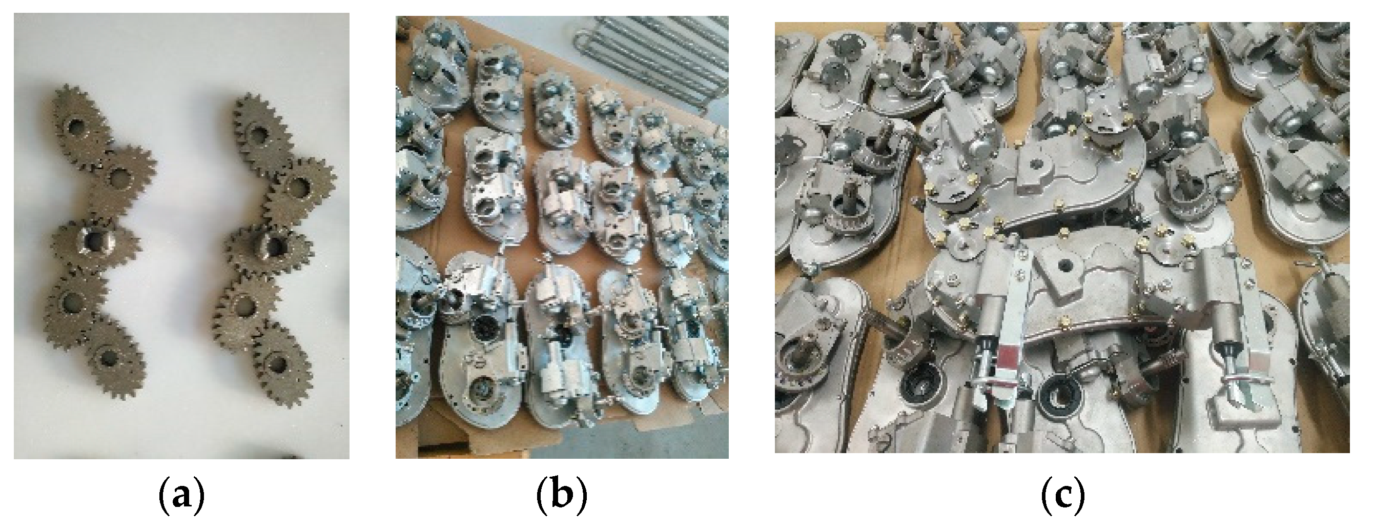
4.1. Design and Manufacture of Non-Circular Gears

The non-circular gear is a crucial component of the core parts of the picking-type transplanting mechanism. By engaging in mutual rotation, the non-circular gears convert the uniform rotation of the planetary carrier into the unequal speed swing of the transplanting arm. This allows the transplanting arm to achieve the necessary trajectory and attitude for successful transplantation. The non-circular gear utilized in the picking-type transplanting mechanism is the “Bezier” gear, with the non-circular-gear pitch curve obtained through the Bezier curve-fitting method [17]. The irregular tooth profile of the non-circular gear is then enveloped by the generating-method principle. Table 2 displays the non-circular-gear design parameters, which are tailored to meet the demands of rice pot-seedling transplantation and mechanism strength.
The manufacture of non-circular gears presents a greater challenge compared with traditional gear shaping or gear hobbing due to their complex tooth profiles, which vary for each individual gear tooth. Ensuring the accuracy of the tooth profile can be difficult. To address this issue, the non-circular gears employed in the picking-type rice pot-seedling transplanting mechanism were produced using an iron-based powder-metallurgy process, as depicted in Figure 9. Upon inspection, it was found that the manufactured non-circular gear exhibited an error of less than ±1 mm; any manufacturing error was limited to the tooth clutch or gear end face. Notably, the non-circular gear’s ability to achieve a high degree of accuracy in the formation of irregular tooth profiles enables it to meet the precise unequal-speed transmission requirements of the picking-type transplanting mechanism.

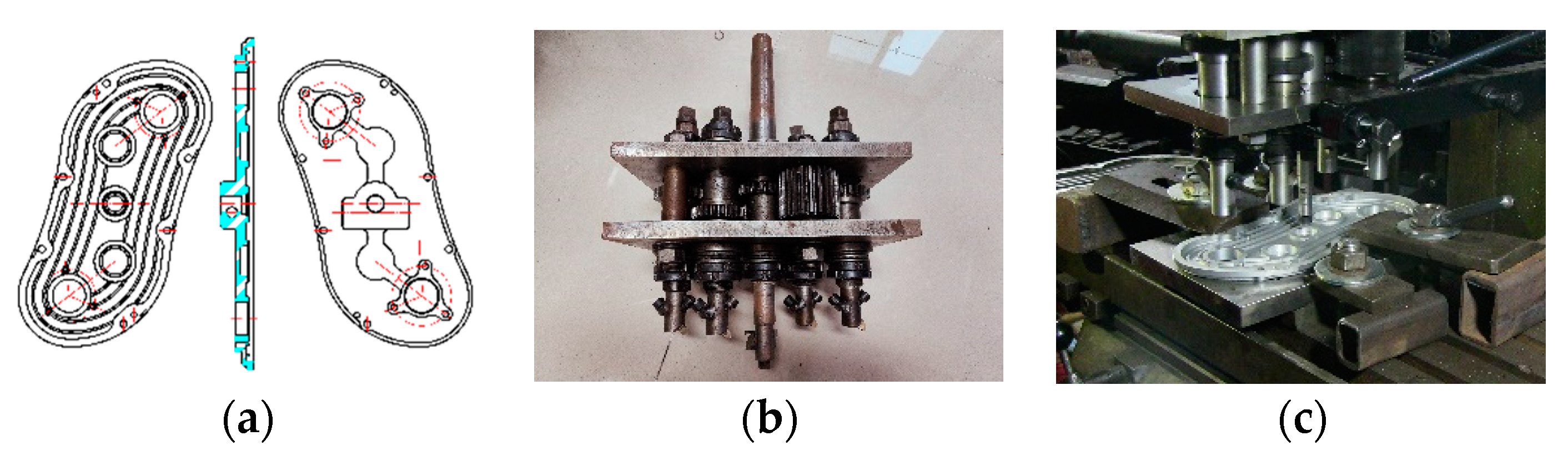
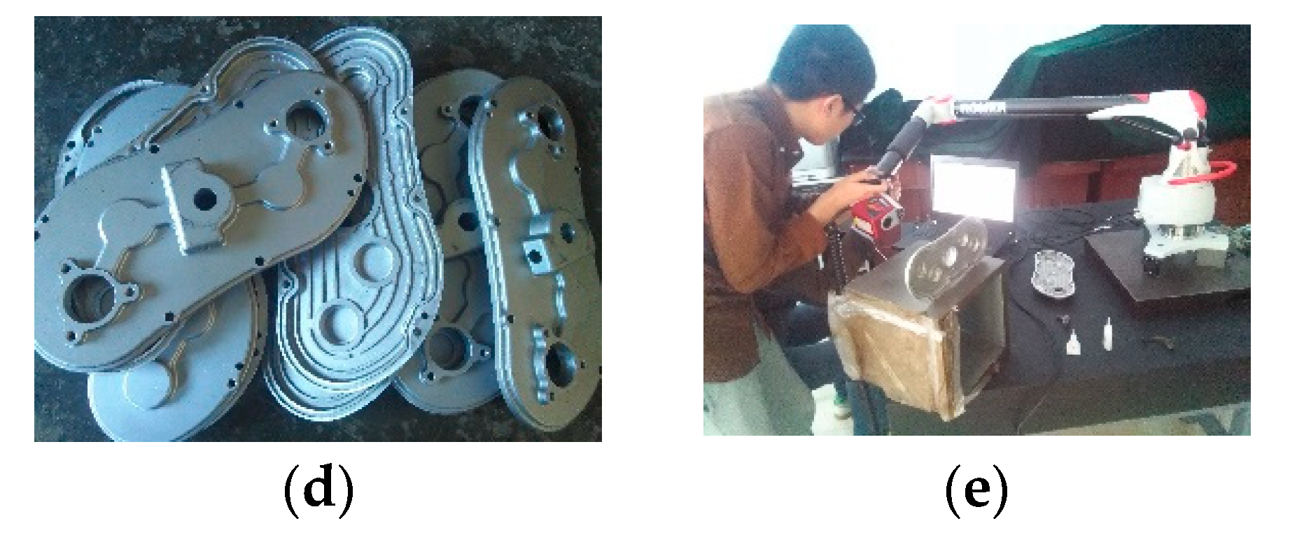
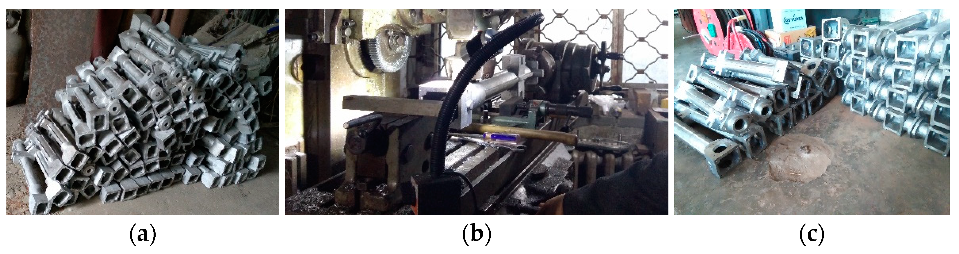
4.2. Design and Manufacture of the Gearbox

The rice pot-seedling transplanting mechanism operates in a working environment that is located in a paddy field. To ensure that the gearbox is properly sealed, an unequal-speed planetary-gear train is required. The gearbox, which is also known as the planetary carrier, supports the engaging rotation of non-circular gears. The machining accuracy of the bearing hole in the gearbox is critical to the non-circular-gear transmission performance. If the hole spacing is too large, it can result in a large clearance on the tooth flank of the non-circular gear, which can ultimately affect the accuracy of the transplanting arm to achieve the desired transplanting trajectory and attitude. On the other hand, if the hole spacing is too small, it can cause the non-circular gear pair to fail to engage and rotate. The design of the gearbox takes into account the center distance of the non-circular gear pair as well as the structural parameters of the transplanting mechanism. The gearbox structure is depicted in Figure 10a. Given the significance of the bearing holes in the gearbox, clamping fixtures and machining tools were developed for the processing of the gearbox in one clamping operation. A special combination tool was designed for the five bearing holes in the gearbox (shown Figure 10b) [18], and five bearing holes (step holes) can be machined in one feed, as shown in Figure 10c. After machining and forming (see Figure 10d) and reverse inspection (shown Figure 10e), it was found that the gearbox processed by the designed clamping fixture and combination tool meets the requirements of non-circular gear-pair transmission.

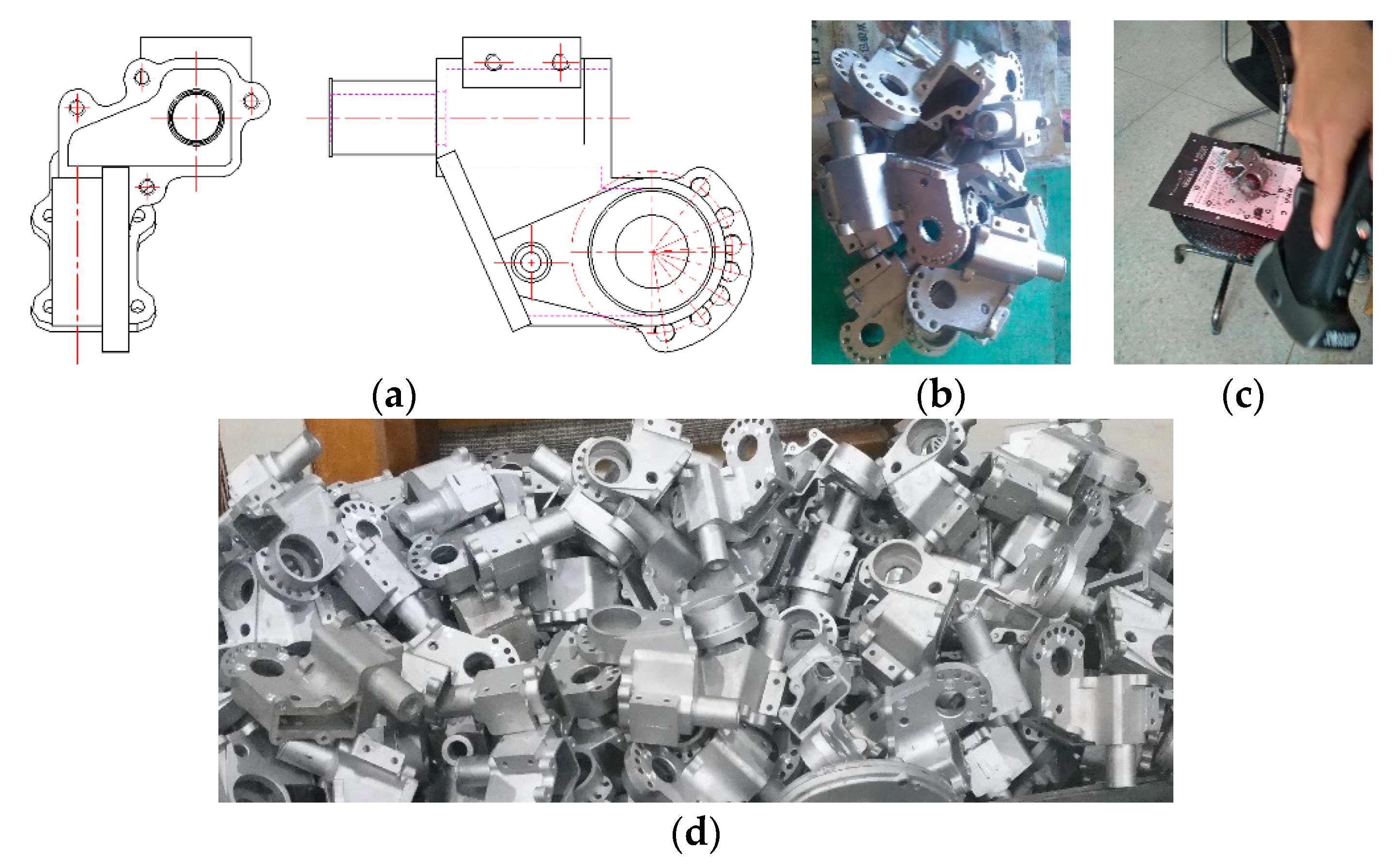
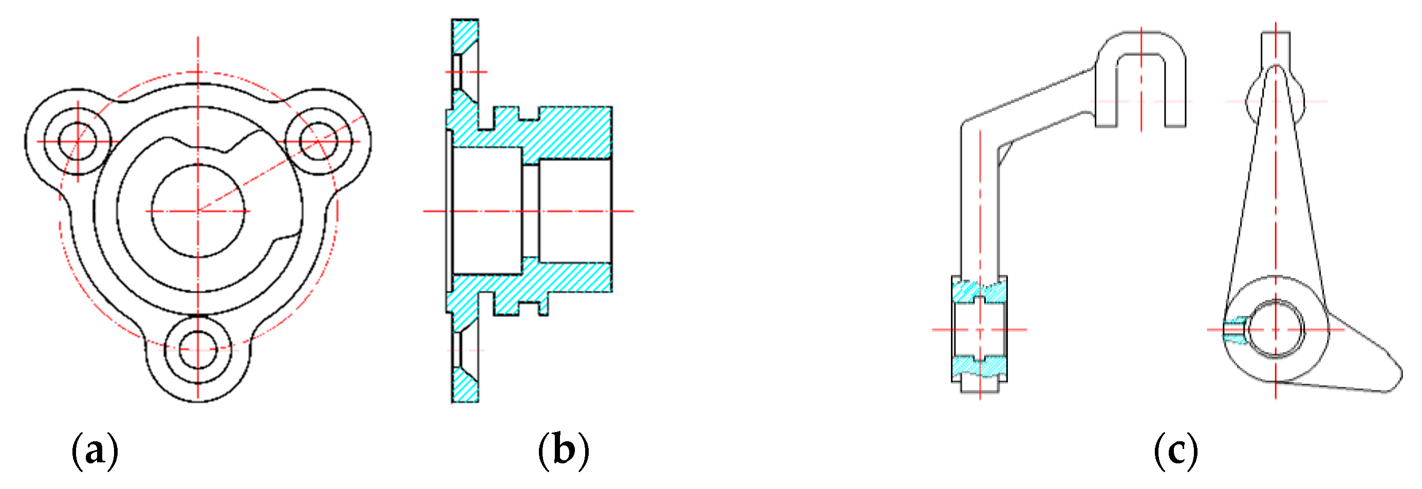
4.3. Design and Manufacture of the Transplanting Arm

The transplanting arm requires various components, including a push rod, clamp slices, a shifting fork, and a spring, all of which come into direct contact with the seedlings and play crucial roles in ensuring the quality of the picking and planting process. To reduce weight and to prevent rusting in the paddy fields, the transplanting arm is constructed from a durable aluminum alloy that undergoes precision casting, as depicted in Figure 11.

4.4. Design and Manufacture of the Cam and Shifting Fork

The gearbox is equipped with a cam that is affixed to it and a transplanting arm that is hinged to a shifting fork. Through the unequal rotation of the transplanting arm relative to the gearbox, the cam and shifting fork form a cam-swing-follower mechanism. In Figure 12, it can be seen that the pusher rod reciprocates to accomplish the clamping and pushing, which are made possible through the matching of the cam and the shifting fork with the spring seat. Figure 13 depict the precise casting and machining processes used to manufacture the cams and shifting forks. The transplanting mechanism of rice pot seedlings has a seedling-picking stage, a seedling-transportation stage, a planting stage and a return stage, and the cam curve is designed according to the movement characteristics of each stage. The cam curve comprises a lifting stage, a return stage, a resting stage and an intermediate stage, and the transplanting mechanism passes through the return stage, intermediate stage, lifting stage, resting stage of the cam successively in a working cycle. When the transplanting mechanism is in the seedling-picking stage, the cam is in the return stage, and the fork swings to drive the seedling-pushing rod to retract. When the transplanting mechanism is in the seedling-transportation stage, the fork is in the intermediate stage of the cam, and the seedling-pushing rod is kept in a contracted state. When the transplanting mechanism is in the planting stage, the fork is in the lifting stage of the cam, and the seedling-pushing rod swings to drive the seedling-pushing rod to push out, and the rice seedling is pushed out. When the transplanting mechanism is in the return stage, the fork is in the resting stage of the cam.

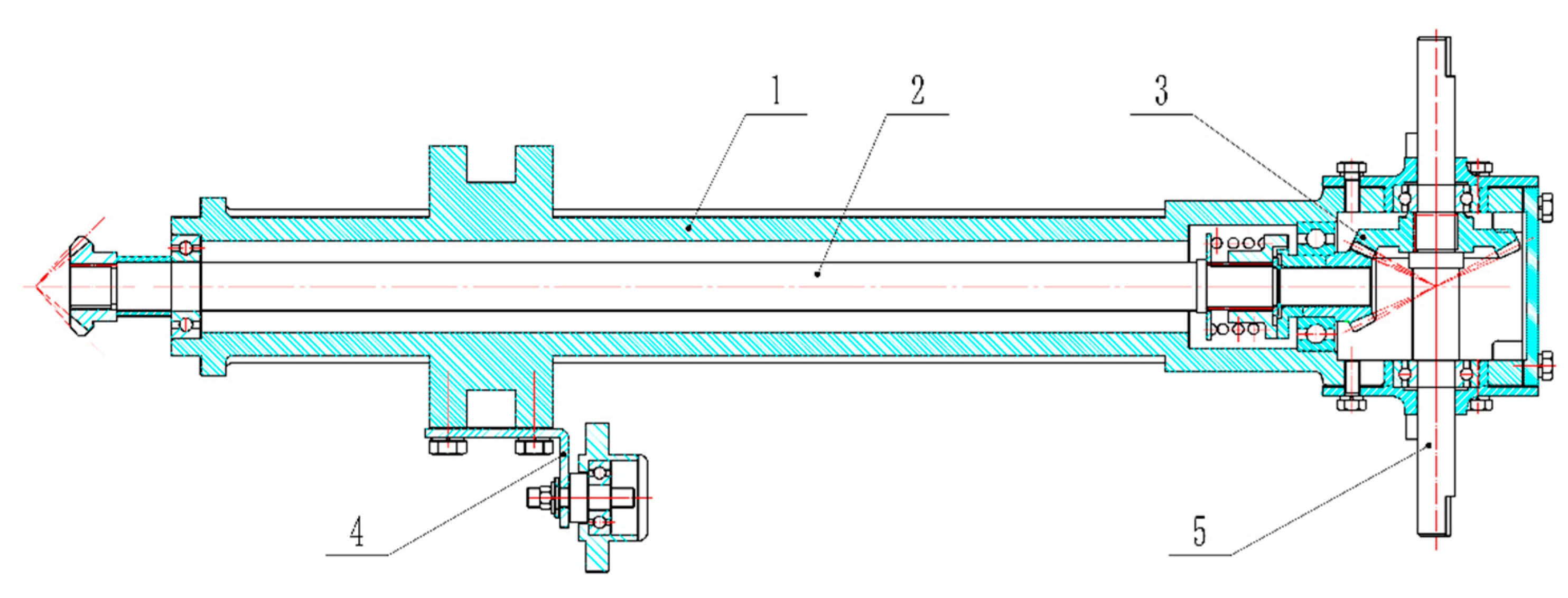
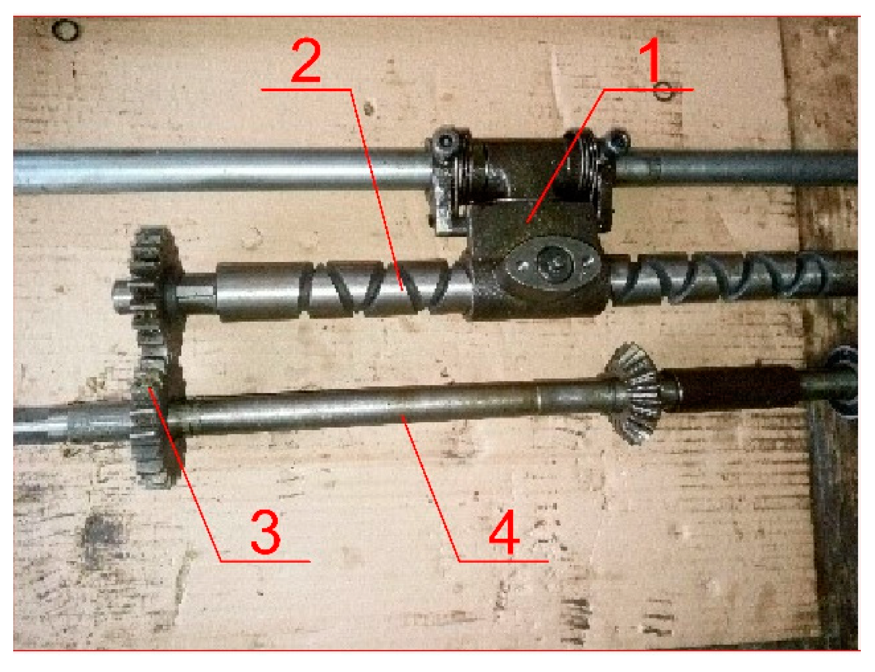
4.5. Design and Manufacture of the Transmission System

The transmission system serves the purpose of transmitting engine power to the transplanting mechanism, enabling it to operate at the same speed as the transplanter’s walking speed. Figure 14 shows the transmission system of the picking-type pot-seedling transplanting mechanism, which comprises the transmission box, transmission shaft, safety clutch, and bevel-gear pair. The gearbox provides support for both the transmission system and the seedling box. In the event that the transplanting mechanism becomes overloaded or comes into contact with stones in the field, the safety clutch is designed to automatically disengage power transmission, thus preventing any potential damage to the transplanting mechanism. Considering that the rice transplanter operates in a paddy field environment, the transmission box undergoes a rigorous process of hard aluminum-alloy casting and sealing, as depicted in Figure 15.

5. Design of the Other Key Devices

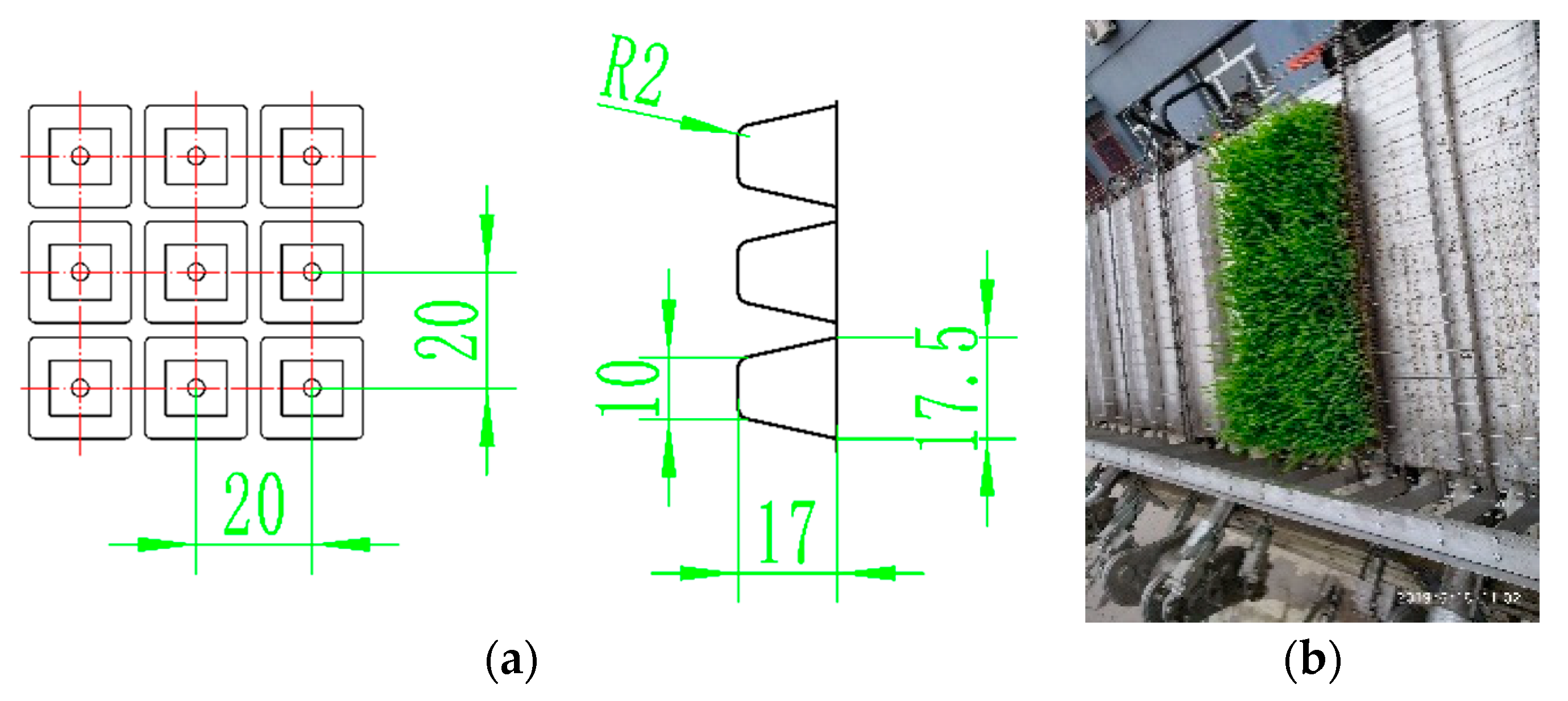
5.1. Design of the Seedling Box

The seedling box plays a crucial role in supporting rice seedlings during the transplanting process. The rice pot seedlings are transplanted in units of holes, requiring precise positioning both vertically and horizontally. Specifically, the rice pot seedlings are transplanted with 14 horizontal holes and 29 longitudinal holes, with a center distance of 20 mm between each hole (as depicted in Figure 16a). The horizontal position of the seedling tray within the seedling box is secured by the bulge on the seedling box, while the longitudinal position is ensured by clamping the tray to the bottom of the seedling tray using steel wire that is interspersed in the chain every three links (as shown in Figure 16b).

5.2. Design of the Seedling Supply System

The rice seedling-supply system comprises a horizontal box-transfer system and a longitudinal rice-feeding system. These two systems work together to supply seedlings to the transplanting mechanism from both the horizontal and longitudinal directions.
The horizontal box-transfer system employs the box-transfer method of the blanket-seedling transplanter [19] (where a spiral axis drives the slider for a reciprocating linear motion) to achieve a lateral rice-seedling supply. To enhance the success rate of picking seedlings and to minimize the rate of seedling injury in the picking-type transplanting mechanism, a traditional transplanter based on the lateral transfer of the seedling box at a constant speed was redesigned for variable speed. During the seedling-picking stage, the seedling box moves slowly, which is conducive to the completion of the seedling-picking action by the transplanting mechanism. On the other hand, the seedling box moves quickly during the process of rice conveying and planting, thereby improving the efficiency of transplanting. In the development of the horizontal box-transfer system, the circular gear pair that drives the rotation of the helical shaft was improved to an elliptical gear pair (as shown in Figure 17). This modification allows the spiral shaft to rotate at a variable speed during the working process, thereby enabling the variable-speed movement of the seedling box. Through the use of the variable-speed transfer box, the movement of the seedling box in the seedling-picking stage was 2.05 mm, which is 1.28 mm less than the lateral movement of the seedling-picking stage of the traditional horizontal seedling box-transfer mechanism. This improvement effectively ensures the success rate of picking seedlings.
The longitudinal system operates by moving a row of seedlings in a longitudinal direction after they have been transplanted transversely (14 holes). This system features the intermittent feeding of seedlings (with seedlings being fed when the box is moved to both ends) and a high-precision feeding of seedlings (since the longitudinal delivery of seedlings has a significant impact on picking seedlings). To address these needs, a ratchet-type seedling-feeding mechanism [20] (as shown in Figure 18) was employed in this study. This mechanism not only guarantees that an accurate number of seedlings is fed at low speed but also prevents excessive seedling delivery due to inertia during high-speed operations.

6. Experimental Research

6.1. Complete Machine Development

The rice pot-seedling transplanting machine’s core working component is the transplanting mechanism. Once assembled according to design specifications, the entire machine can be developed. The assembly process of the transplanting mechanism has been is illustrated in Figure 19.

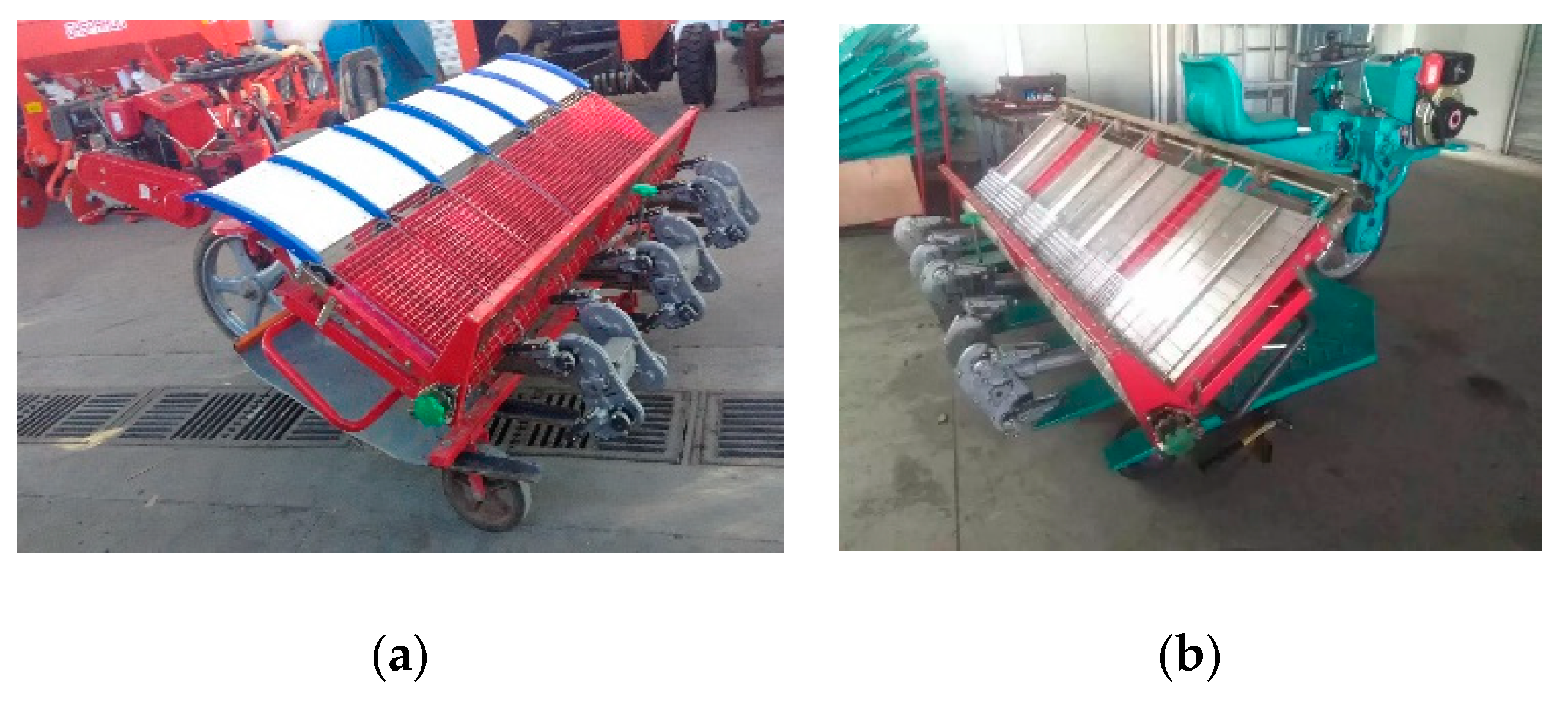
6.1.1. Ordinary Ride-Type Model

When the ordinary ride-type rice pot-seedling transplanting machine is in operation, it is propelled by a walking wheel and utilizes an integral-type floating plate. However, the efficiency of this machine is generally not more than 160 times per minute. Figure 20 displays the ordinary ride-type rice pot-seedling transplanting machine, while Table 3 provides its parameters. Based on the evaluation of the Heilongjiang Agricultural Machinery Test and Appraisal Station, the qualification rate of the planting depth for the ordinary ride-type model machine was 94%, with a seedling-injury rate of only 0.9% and a missed-transplanting rate of 2%.

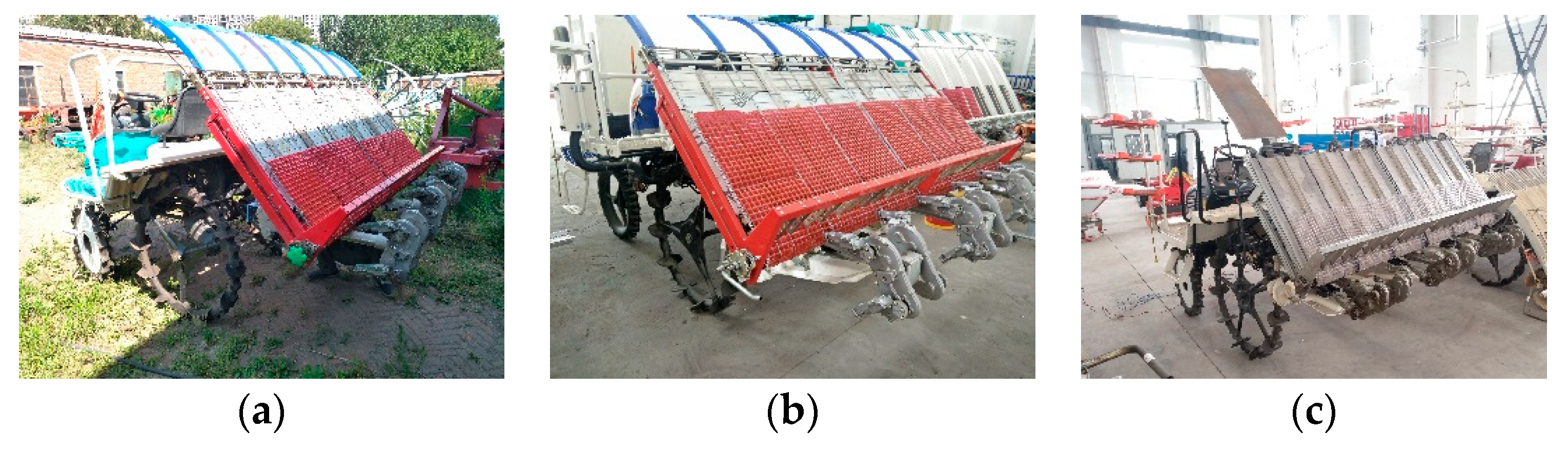
6.1.2. High-Speed Model

The high-speed rice pot-seedling transplanting machine has been upgraded with a chassis that boasts a four-wheel drive and a separation floating plate. Additionally, it features automatic adaptive adjustment of both the horizontal and transplanting depths. The author has designed a transmission system for three models of high-speed transplanters, namely KUBOTA, ISEKI, and TATUNG, and combined them to create high-speed rice pot transplanting machines. Figure 21 showcases the high-speed rice pot-seedling transplanting machine, while Table 4 outlines its parameters. Based on the Heilongjiang Agricultural Machinery Test and Appraisal Station’s report, the high-speed model machine has a 92% qualification rate for the planting depth, a 1.2% seedling-injury rate, and a 2% missed-transplanting rate.

6.2. Field-Transplanting Experiments

Experiments and demonstrations to develop rice pot-seedling transplanting machines have been carried out in various regions, including in Huaian and Haian of Jiangsu Province; Harbin, Daqing, Qiqihar, and Hegang of Heilongjiang Province; Xiangyang and Shiyan of Hubei Province; Changchun of Jilin Province; and Sanya of Hainan Province (as shown in Figure 22). As a result, the field-transplanting work now meets the requirements for rice pot-seedling transplanting, leading to a 5–15% increase in yield. It provides a new way for the mechanized production of rice.
Using an experiment conducted in Xinxiang Village, Liaodian Town, Acheng District, Harbin, Heilongjiang Province as an example, the test conditions were as follows: the rice field was composed of black soil that was soaked for 7 days before being transplanted, after stirring the mud and allowing it to settle. During the transplanting process, the average water depth in the field was 40 mm, while the depth of the mud layer was 150 mm. The average height of the rice seedlings was 169 mm, and the average leaf age was three leaves. The moisture content of the seedbed soil was 37.8%, and the average number of seedlings per hole was 5, with a seedling-tray vacancy rate of 0.62%. The results of the transplanting test, as shown in Table 5, met the local requirements for rice transplantation.

7. Conclusions

(1)
By utilizing a non-circular gear design and developing a pull-out rice pot-seedling transplanting mechanism, it is possible to continuously realize the rice pot-seedling transplanting required for rice seedling division, transport, and planting as well as other actions. The transplanting mechanism is composed of a non-circular-gear train and two planting arms, with two transplanting actions able to be completed in one stroke. This improves the transplanting efficiency and reduces the rate of injury.
(2)
In order to adapt the designed pull-out transplanting mechanism to the transplanting machine, research was carried out on key technologies such as the transmission system, the rice supply system, and the rice box of the rice-bowl transplanting machine. Two types of transplanters, an ordinary ride-type and a high-speed type, were designed and developed. After experimental verification and analysis, both models were shown to achieve the expected transplanting effect of rice-bowl seedlings, with an excellent quality of transplanting.
(3)
Experiments and demonstrations utilizing the specially designed rice pot-seedling transplanting machine have been conducted in numerous locations throughout China. The results have shown a success rate of over 92% for proper planting depth, with less than 1.2% of the seedlings being injured, and less than 2% of the transplantings being missed. Additionally, the floating seedling rate was less than 0.5%, and the tipping rate was less than 3%. These impressive figures have resulted in a yield increase of 5% to 15% compared with traditional blanket-seedling transplanting methods.

Author Contributions

M.Z. completed the design and development of the non-circular-gear transplanting mechanisms and other key components; D.Y. and J.Y. (Jianjun Yin) completed the machining, manufacturing, and testing of the transplanting machine; J.Y. (Jiajia Yang) completed the writing and editing. All authors have read and agreed to the published version of the manuscript.

Funding

This study was financially supported by the Jiangsu Agriculture Science and Technology Innovation Fund (Grant No. CX(22)3089), Key R&D Plan of Zhenjiang City—Modern Agriculture (Grant No. NY2023003), Postgraduate Research & Practice Innovation Program of Jiangsu Province (Grant No. SJCX23_2087), China Postdoctoral Science Foundation (Grant No. 2021M691315), National Natural Science Foundation of China (Grant No. 52005221), Natural Science Foundation of Jiangsu Province (Grant No. BK20200897), Key Laboratory of Modern Agricultural Equipment and Technology (Jiangsu University), High-Tech Key Laboratory of Agricultural Equipment and Intelligence of Jiangsu Province, and Priority Academic Program Development of Jiangsu Higher Education Institutions (Grant No. PAPD-2018-87).

Institutional Review Board Statement

Not applicable.

Data Availability Statement

These data were derived from the following resources available in the public domain: Heilongjiang Agricultural Machinery Test and Appraisal Station and http://www.hnkjdz.org.cn/Home/Apply?channelId=144 (accessed on 22 January 2024).

Conflicts of Interest

The authors declare no conflict of interest.

References

  1. Yu, X.X.; Zhao, Y.; Chen, B.C.; Zhou, M.L.; Zhang, H.; Zhang, Z.C. Current situation and prospect of transplanter. Trans. Chin. Soc. Agric. Mach. 2014, 45, 44–53. [Google Scholar]
  2. Yu, G.H.; Wang, L.; Sun, L.; Zhao, X.; Ye, B.L. Advancement of mechanized transplanting technology and equipments for field crops. Trans. Chin. Soc. Agric. Mach. 2022, 53, 1–13. [Google Scholar]
  3. Rahul, K.; Raheman, H.; Paradkar, V. Design and development of a 5R 2DOF parallel robot arm for handling paper pot seedlings in a vegetable transplanter. Comput. Electron. Agric. 2019, 166, 105014. [Google Scholar] [CrossRef]
  4. Imran, M.S.; Abdul Manan, M.S.; Khalil, A.N.M.; MdNaim, M.K.; Ahmad, R.N. Design of transplanting mechanism for rice intensification (SRI) transplanter in Kedah, Malaysia. Mater. Sci. Eng. 2017, 226, 012036. [Google Scholar] [CrossRef]
  5. Felezi, M.E.; Vahabi, S.; Nariman-zadeh, N. Pareto optimal design of reconfigurable rice seedling transplanting mechanisms ssing multi-objective genetic algorithm. Neural Comput. Appl. 2016, 27, 1907–1916. [Google Scholar] [CrossRef]
  6. Kornecki, T.S.; Kichler, C. Development of a no-till transplanter for walk-behind tractors. Appl. Eng. Agric. 2022, 38, 865–872. [Google Scholar] [CrossRef]
  7. Xue, K.; Gao, K.J.; Kuang, F.M.; Zhang, S.; Liao, J.; Zhu, D.Q. Machinery-plant-paddy soil coupling model based numerical simulation method of mechanical transplanting process of big rice seedling. Comput. Electron. Agric. 2022, 198, 107053. [Google Scholar] [CrossRef]
  8. Tong, Z.P.; Yu, G.H.; Zhao, X.; Liu, P.F.; Ye, B.L. Design of vegetable pot seedling pick-up mechanism with planetary gear train. Chin. J. Mech. Eng. 2020, 33, 63. (In English) [Google Scholar] [CrossRef]
  9. Yu, G.H.; Jin, Y.; Chang, S.S.; Ye, B.L.; Gu, J.B.; Zhao, X. Design and test of clipping-plug type transplanting mechanism of rice plug-seedling. Chin. Soc. Agric. Mach. 2019, 50, 100–107. [Google Scholar]
  10. Sun, L.; Xing, Z.Q.; Xu, Y.D.; Liu, B.; Yu, G.H.; Wu, C.Y. Transplanting mechanism of rice seedling based on precise multi-position analysis. Chin. Soc. Agric. Mach. 2019, 50, 78–85. [Google Scholar]
  11. Zhou, Y.Q.; He, L.; Gu, L. Parameters optimization of seperating-planting mechanism for high-speed transplanting for super-rice based on virtual prototyping technology. Mach. Des. Res. 2019, 35, 62–65. [Google Scholar]
  12. Wang, L.; Sun, L.; Xu, Y.; Yu, G.; Gervais, N.L.; Huang, J. Multi-pose motion synthesis of three-arm gear train planting mechanism based on genetic algorithm. Trans. Chin. Soc. Agric. Mach. 2022, 53, 70–77. [Google Scholar]
  13. Yao, Y.F.; Zhu, D.Q.; Wang, Y.Q.; Xiong, W.; Wang, C.X.; Yuan, J.H. Structure design and test of high-speed rice transplanter deesling box with adjustable row spacing. ASME J. Mach. Des. 2016, 33, 80–85. [Google Scholar]
  14. Zhao, X.; Liao, H.; Ma, X.; Dai, L.; Yu, G.; Chen, J. Design and experiment of double planet carrier planetary gear flower transplanting mechanism. Int. J. Agric. Biol. Eng. 2021, 14, 55–61. [Google Scholar] [CrossRef]
  15. Li, F.; Lei, J.; Wang, W.B.; Song, B. Optimal Design and Experimental Verification of a Four-claw Seedling Pick-up Mechanism Using the Hybrid PSO-SA Algorithm. Span. J. Agric. Res. 2022, 20, e0207. [Google Scholar] [CrossRef]
  16. Ao, M.; Yu, G.H.; Wang, L.; Sun, L.; Zhao, J. Optimization synthesis of hybrid six-bar mechanism with non-circular gear constraints. ASME J. Mech. Des. 2023, 145, 064502. [Google Scholar] [CrossRef]
  17. Cheng, Y.H.; Chen, Y.C. Design, analysis, and optimization of a strain wave gear with a novel tooth profile. Mech. Mach. Theory 2022, 175, 104953. [Google Scholar] [CrossRef]
  18. Xu, X.; Zhou, M.L.; Chen, X.G.; Yang, J.J. Processing method of gearbox with non-circular gear train and its application in rice potted seedling transplanting mechanism. Agriculture 2022, 12, 1676. [Google Scholar] [CrossRef]
  19. Yu, G.H.; Du, L.H.; Li, G.; Xu, Y.P.; Ye, B.L.; Liu, D.Q. Design and experiment of feeding-seedling device for high-speed rice pot-seedling transplanter. Trans. Chin. Soc. Agric. Mach. 2015, 46, 39–45. [Google Scholar]
  20. Na, M.J.; Song, Z.C.; Zhou, M.L.; Zhu, H.X.; Wang, Q.; Zhao, Y. Design and experiment on longitudinal seedling feeding mechanism for rice pot seedling transplanting with ratchet gear. Trans. Chin. Soc. Agric. Mach. 2015, 46, 43–47. [Google Scholar]
Figure 1. Comparison of rice-transplanting and seedling-picking methods. (1. Blanket seedlings; 2. Seedling tray; 3. Pot seedlings; 4. Seedling hole-tray).
Applsci 14 01027 g001
Figure 2. Transplanting-mechanism composition.
Applsci 14 01027 g002
Figure 3. Transplanting-arm components.
Applsci 14 01027 g003
Figure 4. Transplanting trajectory and attitude at a key position. (a) Clamping position; (b) Picking position; (c) Conveying position; (d) Planting position. (1. Transplanting arm; 2. Rice seedlings; 3. Seedling box; 4. Transplanting trajectory).
Applsci 14 01027 g004
Figure 5. Schematic diagram of transplanting mechanism of non-circular gears.
Applsci 14 01027 g005
Figure 6. Vector-motion model of the non-circular-gear transplanting mechanism.
Applsci 14 01027 g006
Figure 7. Kinematic simulation of the transplanting mechanism of rice pot seedlings. (a) Simulation of seedling picking and seedling pushing; (b) Seedling transport and return phase.
Applsci 14 01027 g007
Figure 8. Simulated displacement and velocity curves of the rice seedling−transplanting mechanism. (a) Displacement curve of the planting arm; (b) Variation curve of the planting-arm speed.
Applsci 14 01027 g008
Figure 9. Design and detection of non-circular gears. (a) Non-circular sun gear; (b) Non-circular middle gear; (c) Non-circular planetary gear.
Applsci 14 01027 g009
Figure 10. Gearbox. (a) Mechanical design; (b) Combination tool; (c) In the course of working; (d) Final products; (e) Inverse inspection.
Applsci 14 01027 g010aApplsci 14 01027 g010b
Figure 11. Design of the transplanting arm. (a) Mechanical design; (b) Casting; (c) Inverse inspection; (d) Final products of the transplanting arm.
Applsci 14 01027 g011
Figure 12. Cam and shifting fork design. (a) Cam structure; (b) Shifting fork; (c) Working principle.
Applsci 14 01027 g012
Figure 13. Processing and manufacturing of cams and shifting forks. (a) Cam mold; (b) Shifting-fork mold; (c) Casting the cam; (d) Casting the shifting fork; (e) Cam processing; (f) Shifting-fork processing.
Applsci 14 01027 g013
Figure 14. Transmission system design. (1. Transmission box; 2. Transmission shaft; 3. Bevel-gear pair; 4. Safety clutch; 5. Sun shaft).
Applsci 14 01027 g014
Figure 15. Transmission-box manufacturing. (a) Casting; (b) Processing; (c) Final products.
Applsci 14 01027 g015
Figure 16. Seedling box design. (a) Size of the seedling tray; (b) Seedling box.
Applsci 14 01027 g016
Figure 17. Horizontal seedling box-transfer system. (1. Crescent-moon dowel; 2. Reciprocating lead screw; 3. Gear pair; 4. Transmission shaft).
Applsci 14 01027 g017
Figure 18. Longitudinal seedling feeding system. (a) Working principle; (b) Final products.
Applsci 14 01027 g018
Figure 19. Assembly of the transplanting mechanism. (a) Non-circular gear-assembly relationship; (b) Transplanting-mechanism assembly; (c) Several sets of transplanting mechanisms.
Applsci 14 01027 g019
Figure 20. Ordinary ride-type rice pot-seedling transplanting machine. (a) Solid floating-plate type; (b) Hollow floating-plate type.
Applsci 14 01027 g020
Figure 21. High-speed rice pot-seedling transplanting machine. (a) KUBOTA type; (b) ISEKI type; (c) TATUNG type.
Applsci 14 01027 g021
Figure 22. Field-transplanting work. (a) Ordinary ride-type model machine; (b) High-speed model machine.
Applsci 14 01027 g022
Table 1. Digital transplanting trajectory and attitude.
Seedling-Picking AngleSeedling-Pushing AngleAngle DifferencePicking HeightPicking Swing AngleGround DistanceTrajectory Height
1.55°53.13°51.58°34.8 mm4.13°20.75 mm277.3 mm
Table 2. Non-circular gear parameters.
Number of TeethModulusPressure AngleAddendum CoefficientCoefficient of Bottom ClearanceCenter-To-Center DistanceMaximal Modification Coefficient
212.57532010.25520.45
Table 3. Main technical parameters of the ordinary ride-type rice pot-seedling transplanting machine.
PowerWeightRow CountRow SpaceMin Distance of the HoleMax Distance of the HolePlanting Depth
4.2 Kw290 Kg6300 mm140 mm240 mm0–46 mm
Table 4. Main technical parameters of the high-speed rice pot-seedling transplanting machine.
PowerWeightRow CountRow SpaceMin Distance of the HoleMax Distance of the HolePlanting Depth
13.2 Kw720 Kg6300 mm140 mm240 mm10–40 mm
Table 5. Test results.
Transplanting EfficiencyQualification Rate of Planting DepthSeedling-Injury RateMissed-Transplanting RateTipping Rate
140 times per minute92%0.8%1.4%1.7%
180 times per minute94%1.1%1.5%2.3%
220 times per minute93%1.2%2%3%
Disclaimer/Publisher’s Note: The statements, opinions and data contained in all publications are solely those of the individual author(s) and contributor(s) and not of MDPI and/or the editor(s). MDPI and/or the editor(s) disclaim responsibility for any injury to people or property resulting from any ideas, methods, instructions or products referred to in the content.

