Article

Experimental Study on the Flexural and Shear Performance of Concrete Beams Strengthened with Prestressed CFRP Tendons

1
School of Civil & Environmental Engineering and Geography Science, Ningbo University, Ningbo 315211, China
2
IOT Technology Application Transportation Industry R&D Center (Hangzhou), Hangzhou 311106, China
*
Author to whom correspondence should be addressed.
Appl. Sci. 2024, 14(3), 1237; https://doi.org/10.3390/app14031237
Submission received: 3 January 2024 / Revised: 26 January 2024 / Accepted: 28 January 2024 / Published: 1 February 2024
(This article belongs to the Section Civil Engineering)

Abstract

:
To investigate the influence of external prestressing with carbon fiber-reinforced polymer (CFRP) tendons on the flexural and shear performance of reinforced concrete beams, a total of six simply supported beams with a length of 3.5 m and two two-span continuous beams with a length of 7 m were studied. The influences of the prestressing level of CFRP tendons, the pattern of straight-line and flexural reinforcement of externally prestressed CFRP tendons, and the existence of initial cracks in the beams on the flexural bearing capacity of the reinforced beams were explored through modeling tests. The calculating equation for anticipating the ultimate flexural bearing capacity of concrete beams reinforced with externally prestressed CFRP tendons was modified based on the test results. The findings indicate that the flexural bearing capacity of the test beams was significantly enhanced through both flexural and straight-line reinforcement. Specifically, the ultimate flexural bearing capacity of the simply supported beams exhibited improvements of approximately 160% and 170%, respectively, whereas the ultimate flexural bearing capacity of the continuous beams was enhanced by approximately 113% through the reinforcement of flexural arrangement. Additionally, the shear resistance capacity of the concrete beams was notably improved through the flexural arrangement reinforcement, and the shear resistance capacity of the beams exhibited a substantial increase as the prestressing level of the CFRP tendons increased. The flexural moments in the vicinity of the support point of the reinforced beam exhibited an increase ranging from 41.7% to 112.5% when the stirrup strains started to escalate rapidly. Additionally, the rigidity of the test beams showed a close correlation with both the prestressing level and the existence of initial cracks.

1. Introduction

The utilization of concrete structures is of crucial significance in modern architectural and infrastructural projects. The factors related to flexural and shear performance have always been considered critical criteria that require particular focus throughout the design and construction phases. Concrete beams that are either simply supported or continuous are frequently used as structural components. These beams are subjected to cyclic loads or are exposed to corrosive conditions over time, which ultimately results in the accumulation of damage and a decline in performance [1]. Extensive research spanning decades has demonstrated that the application of external prestressing techniques not only enhances the structural flexural and shear capacity but also contributes to an improvement in rigidity [2,3,4]. Researchers have initiated the evaluation and application of fiber-reinforced polymer (FRP) tendons as a viable and environmentally friendly substitute for traditional steel reinforcement, owing to the notable progress in FRP tendon manufacturing technology [5,6,7,8]. In comparison with traditional reinforcing materials, FRP composites provide a linear elastic response without a distinct yield point. Additionally, these composites offer the advantage of flexible arrangement, possess high specific strength, exhibit exceptional resistance to corrosion, and are non-magnetic [9,10,11]. The utilization of carbon fiber-reinforced polymer (CFRP) materials has been extensively employed for the purpose of flexural and shear reinforcement in reinforced concrete beams [12,13].
In recent decades, researchers have extensively explored the use of CFRP materials for the externally prestressed flexural or shear reinforcement of concrete beams. Luo et al. [14] and Pirayeh et al. [15] investigated the flexural performance of concrete beams reinforced with externally prestressed CFRP tendons. In their study, they compared the results with beams that were strengthened with externally prestressed steel-stranded wire. The modulus of elasticity associated with CFRP materials is comparatively lower than that of steel-stranded wire. This discrepancy results in a discernible reduction in rigidity and an increase in deflection after the occurrence of cracking, thus emphasizing the importance of mid-span deflection in concrete beams that are reinforced with CFRP materials under normal operating conditions. Habib et al. [16] used CFRP strips to provide separated reinforcement to the positive and negative moment regions of continuous beams. Their experimental findings suggest that the beams reinforced in both positive and negative moment regions exhibit a higher ultimate load capacity compared to the beams reinforced only in the negative moment zone. Buyle-Bodin et al. [17] and Xue et al. [18] conducted experimental testing on concrete beams reinforced with CFRP materials, with a focus on investigating the influence of the initial damage level on the test results. Their findings indicate that the initial level of damage had a limited impact on both the ultimate load-bearing capacity and the ductility of concrete beams reinforced through external prestressing. However, a positive correlation was observed between the initial damage level and the mid-span deflection during the loading process. Frosch et al. [19] and Tureyen et al. [20,21] demonstrated that augmenting the extent of internal flexural reinforcement in concrete beams resulted in a corresponding enhancement of their shear capacity. Hence, it is anticipated that the augmentation of shear capacity through the use of externally prestressed CFRP tendons will have a comparable effect to that achieved by internal reinforcement. Dong et al. [22] and Hawileh et al. [23] conducted an empirical investigation on the strengthening of reinforced concrete beams in both flexural and flexural–shear conditions with FRP sheets. Their study showed that the pattern of flexural–shear arrangement is more efficacious than the arrangement of flexural reinforcement in enhancing the rigidity, ultimate flexural bearing capacity, and post-cracking performance of reinforced concrete beams. Shang et al. [24] investigated the reinforcement and damage properties of cracked CFRP–concrete beams using the digital image correlation method and proposed a simple method for evaluating the reinforcement effect of cracked CFRP–concrete beams, which was verified by experimental results. The authors suggested that the reinforcement effect of cracked CFRP–concrete beams should be evaluated during service. Sun et al. [25] investigated the bending behavior of reinforced concrete beams reinforced with CFRP tendons by creating a finite element model that elucidated the damage mode of the beams in terms of displacement evolution and strain development. In addition, the experimental results revealed the influences of the bar connection mode. RC beams strengthened with continuous bars have a greater ultimate load than those strengthened with lapped bars. Naaman et al. [26], Arvainthan et al. [27], and Xu et al. [28,29] derived the calculation equation of the ultimate stress and flexural bearing capacity of externally prestressed CFRP concrete beams under static loading by analyzing the short-term performance of externally prestressed CFRP concrete beams. Additionally, the predicted results exhibited a high level of agreement with the test results. In a study conducted by Wang et al. [30], it was demonstrated that the arrangement of flexural reinforcement resulted in a notable reduction in mid-span deflection and enhanced the overall performance of the beams subjected to uniform loads. The study of Abushanab et al. [31] demonstrated that when damage occurs at the mid-span, there is a linear drop in the ultimate load as the distance between deviators increases.
The majority of previous research has mostly focused on utilizing CFRP reinforcement to enhance flexural or shear resistance individually. There are limited studies on the use of CFRP reinforcement to enhance the flexural and shear capacities of both simply supported and continuous beams. In this paper, a series of tests were designed to verify the effectiveness of external prestressed CFRP tendons to enhance the flexural and shear load-carrying capacity of concrete beams strengthened simultaneously. In this study, a total of eight reinforced concrete beams were fabricated and enhanced with externally prestressed CFRP tendons. The beams consisted of both simply supported and continuous beams. This research employs experiments to comprehensively examine the influence of the reinforcement arrangement of CFRP concrete beams, the prestressing level, and the presence of initial cracks on the flexural and shear performance of the beams. Furthermore, this paper examines the equations used to anticipate the ultimate flexural bearing capacity of concrete beams that are reinforced with externally prestressed CFRP tendons.

2. Experimental Design

2.1. Sample Preparation

This study experimentally investigates the enhancement of the flexural performance of concrete beams by externally prestressed CFRP tendons. The information regarding the test beams (six simply supported and two continuous) is described in Table 1, which includes the prestress levels and arrangement patterns of the CFRP tendons, and pre-existing cracks. The dimensions and reinforcement forms of the beams are shown in Figure 1. The cross-section dimension of the beam is 200 mm × 400 mm, where the arrangement of CFRP tendons is categorized into two forms: straight-line and curved pattern. The term “Damage State” in Table 1 pertains to the preloading of the test beams until the maximum crack width in the tension zone reaches 0.2 mm. This width is twice the maximum permissible crack width ω m a x for prestressed concrete members under normal service conditions as stipulated in Code (GB50010-2010) [32].
Each tested beam is identified in this research by a particular set of acronyms. The first letter represents the beam’s support condition, with “S” denoting simply supported beams and “C” denoting continuous beams. The second letter represents the arrangement pattern of the CFRP tendons, with “SL” standing for a straight-line and “C” for a curved pattern, respectively. The third letter indicates the initial prestress level of the external CFRP tendons, with “0”, “30”, and “50” representing prestressing levels of 0%, 30%, and 50%, respectively. The fourth letter denotes the width of pre-existing cracks: “0” indicates the absence of initial flexural cracks, while “0.2” signifies preloading to achieve a flexural crack width of 0.2 mm.

2.2. Material Properties

To ascertain the mean compressive strength of the test beams, six concrete cube specimens were concurrently fabricated throughout the concrete placing process of the test beams. Following the curing process, the specimens underwent uniaxial compression testing. Furthermore, the plain steel and CFRP tendons utilized in the beams were subjected to tensile testing to determine their average yield and ultimate tensile strengths. Table 2 displays the material parameters of concrete, steel, and CFRP tendons. Figure 2 shows the stress–strain curve for each material.
As shown in Figure 2a, at the peak strength point of the stress–strain curve, a maximum stress value of 2123 MPa was observed, with an associated strain of 8866 με. This point represents the ultimate capacity of the CFRP tendon prior to rupture. Rupture of the CFRP tendon is closely linked to the behavior observed in the stress–strain curve; this curve demonstrated a linear relationship, with the stress being uniformly applied to the CFRP tendon until the ultimate strain was reached. With increasing applied moment, the material undergoes elastic deformation until it reaches the ultimate strain. The rupture point is characterized by a sudden drop in stress, indicating the failure of the CFRP tendon. The strain value at rupture yields crucial information regarding the material’s ductility and brittleness. In this study, the CFRP tendon ruptured at a strain of 8866 με, underscoring the material’s capacity to withstand substantial deformation prior to ultimate failure. This analysis of the stress–strain curve not only augments our understanding of the mechanical behavior of the CFRP tendon but also offers valuable insights for structural design considerations and safety assessments.

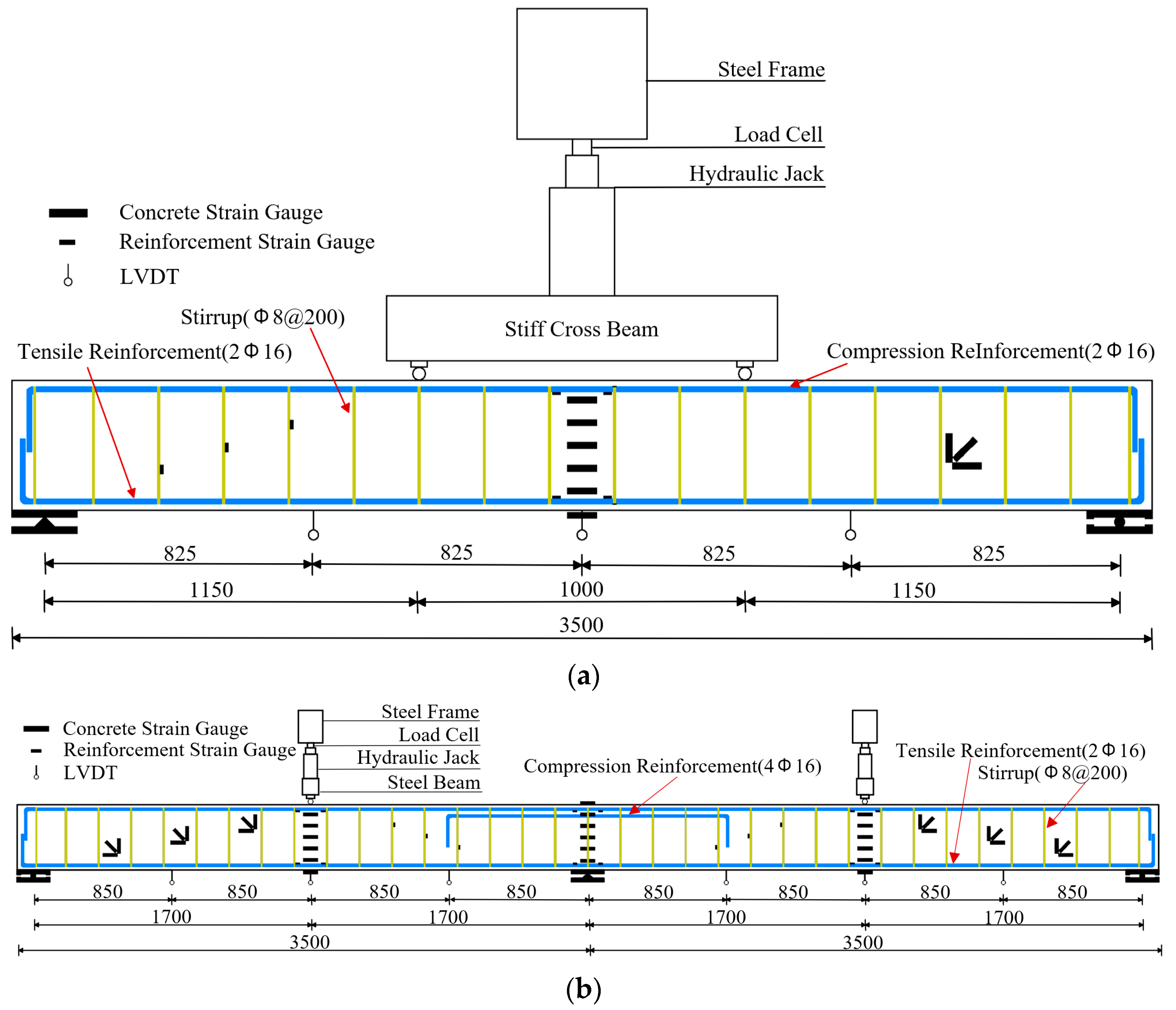
2.3. Test Setup and Loading Procedures

The experimental examination utilized four-point flexural tests for the externally prestressed CFRP simply supported beams, while five-point flexural tests were conducted for the continuous beams, as depicted in Figure 3. A 1000 kN hydraulic jack was used for loading. Linear displacement sensors were positioned at the mid-span and quarter-span locations of the test beams to observe and record changes in deflection occurring during the loading process. During the experimental tests, strain gauges were attached to the surfaces of the steel rebars, CFRP tendons, and concrete beams to measure the tensile and compressive strains. Load sensors with a maximum capacity of 220 kN were placed at the fixed ends of the external CFRP tendons. These sensors were utilized to continuously monitor the axial forces exerted on the CFRP tendons during the tensioning and loading processes.
The loading procedure consisted of applying load increments of 5 kN, each maintained for a duration of 5 min. In instances when the beam’s deflection demonstrated discernible non-linearity or approached its ultimate load, a loading rate of 3 mm/min, regulated by displacement, was used until failure occurred. Force sensors with a maximum capacity of 440 kN were used to monitor the externally imposed loads during the loading process. Furthermore, following each loading phase, a handheld crack width gauge with a precision of 0.02 mm was used to measure the widths of the cracks.

3. Results and Discussion

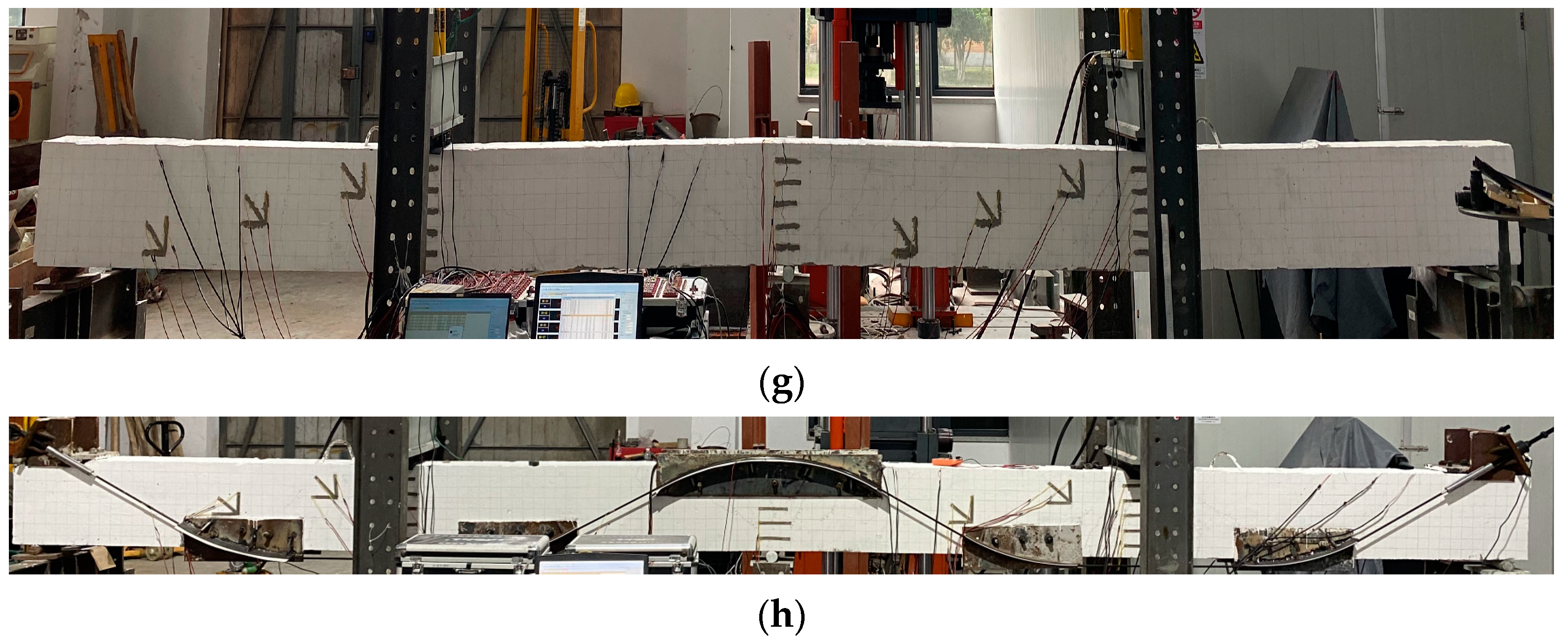
3.1. Failure Modes and Flexural Moments

The failure modes exhibited by the test beams can be classified into three distinct categories: (1) Typical Flexural Failure (Figure 4a,g). Once the yield moment is reached, the steel reinforcements within the beam begin to yield. The mid-span deflection demonstrates noticeable non-linearity until it reaches its maximum flexural bearing capacity. (2) Concrete Compression Failure in the compression zone (Figure 4e). In cases where the prestressing level of externally prestressed CFRP tendons is relatively low, a notable mid-span deflection arises following the yielding of steel reinforcements and persists until the beam failure stage. At this time, excessive compressive strain is generated in the compression zone, resulting in premature failure. (3) Failure of Beam Flexure due to Rupture of CFRP Tendon. In situations with significant external prestress, the CFRP tendons rupture and can no longer bear any load upon reaching their ultimate strain. At this point, the beam still supports a high level of external load, resulting in a rapid increase in mid-span deflection, leading to the beam’s flexural failure.
Table 3 presents the characteristic flexural moments and failure modes of each test beam. The experimental results show that externally prestressed reinforcement using CFRP tendons can enhance the cracking moment, effectively delaying the yielding of the steel reinforcement and improving the ultimate flexural bearing capacity. Upon comparing specimens SCB, S-C-0-0, and S-C-30-0, it was noted that the application of prestressed CFRP tendons resulted in an increase in the ultimate flexural bearing capacities of the simply supported beams. Specifically, the flexural bearing capacities improved from 65.6 kN·m to 160.6 kN·m (a 145% improvement) and 172.8 kN·m (a 163% improvement) for specimens S-C-0-0 and S-C-30-0, respectively. In comparison to the beam CCB, the continuous beam C-C-30-0 experienced a significant increase in its ultimate flexural bearing capacity, rising from 75.1 kN·m to 159.6 kN·m (a 113% improvement). By applying an external prestress of 30% to the CFRP tendons, the flexural bearing capacity of the simply supported beam increased by 107.2 kN·m, whilst the continuous beam saw an increase of 84.5 kN·m in its flexural bearing capacity. This indicates that under the same external prestressing condition of the CFRP tendons, the increase in the ultimate flexural bearing capacity of the simply supported beams is greater than that of the continuous beams.
The test beams S-C-0-0 and S-C-30-0 have ultimate flexural bearing capacities of 160.6 kN·m and 172.8 kN·m, respectively. In contrast, it can be observed that increasing the prestressing level in externally prestressed CFRP tendons results in a mere 7.6% increase in the ultimate flexural bearing capacity. This implies that merely altering the prestressing level of the CFRP tendons cannot significantly enhance the ultimate flexural bearing capacity of the concrete beams. The ultimate flexural bearing capacity of the specimen S-C-30-0.2 is 168 kN·m. Compared to the specimen S-C-30-0, with a capacity of 172.8 kN·m, the ultimate flexural bearing capacity decreased only by 2.8%. This indicates that the initial damage incurred by the reinforced test beams has a negligible impact on their ultimate flexural bearing capacity. It can therefore be concluded that the influence of the prestressing level and the initial cracks on the ultimate flexural load-carrying capability of the beams is relatively insignificant. In comparison to the SCB specimen, the beams S-SL-0-0 and S-C-0-0 showed increases in their ultimate flexural bearing capacity of 170.7% and 144.8%, respectively. This finding indicates that the increase in flexural carrying capacity obtained by the application of straight-line reinforcement is more significant than that achieved through curved reinforcement.

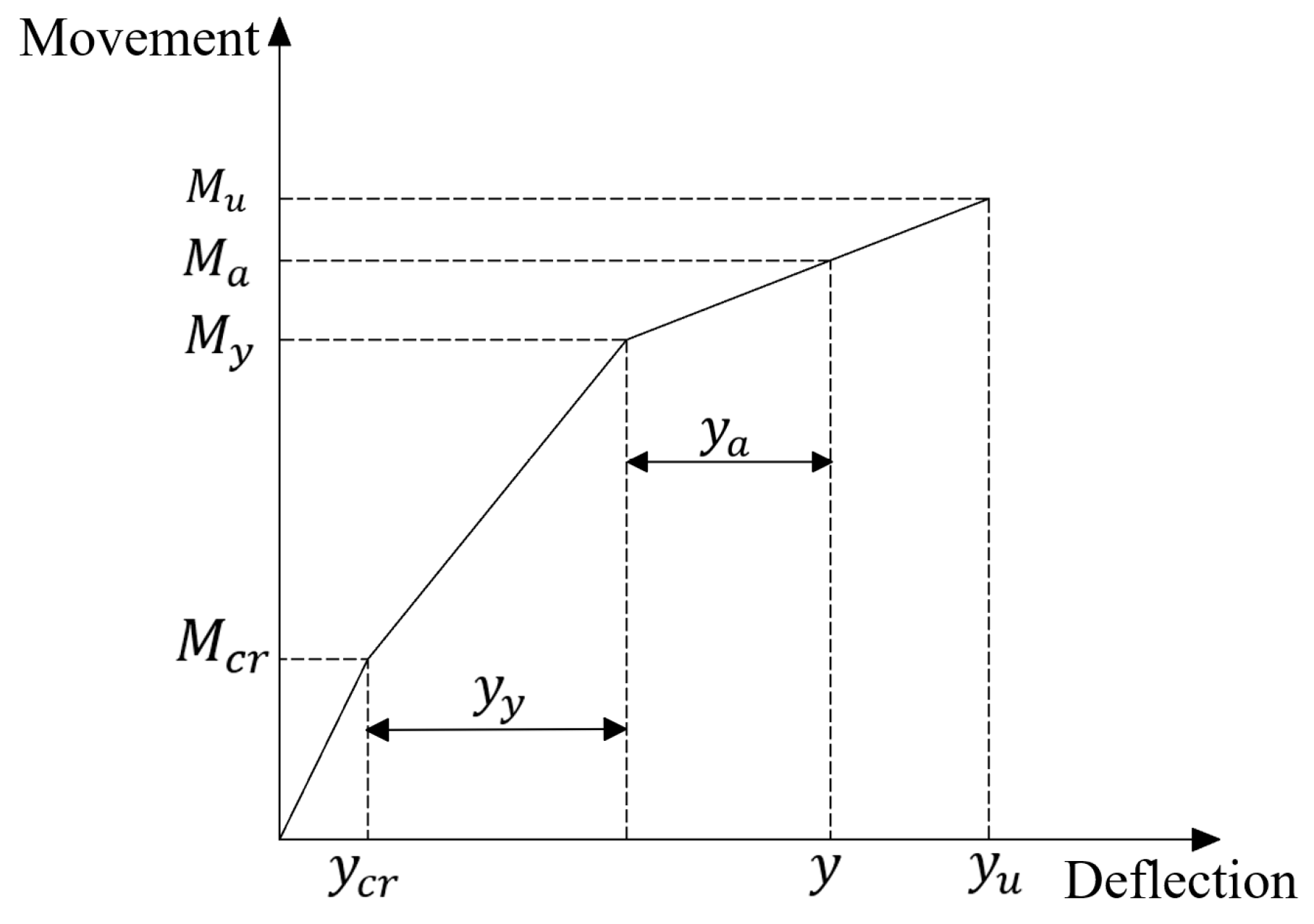
3.2. Moment–Deflection Behavior

Figure 5 illustrates the relationship between mid-span deflection and flexural moment for all specimens. The deflection–moment behavior exhibited by the test beams can be approximated as a tri-linear response. In Phase I, when the beam is uncracked, it demonstrates the highest rigidity. During Phase II, the beam exhibits characteristics of multi-point micro-cracking caused by the combined force-bearing of steel reinforcement and CFRP tendons. The rigidity of the beam in this phase is lower than that of Phase I. During Phase III, the steel reinforcement undergoes yielding, leading to a subsequent decrease in rigidity. This leads to a significant increase in mid-span deflection, ultimately culminating in the failure of the test beam. During the course of these three phases, there is a gradual reduction in the flexural rigidity of the beam. This implies that a strong correlation exists between the short-term deflection of beams reinforced with externally prestressed CFRP tendons and the initial cracks.
In Phase I, the slopes of all curves are essentially consistent. Once the breaking load is attained, the disparities in mid-span deflection among the test beams are relatively minor. The reason for this phenomenon is that applying external prestress with CFRP tendons results in an inverted arch in the mid-span of the concrete beams. As the external load surpasses the de-compression load, the concrete beams exhibit downward deflection. Hence, upon reaching the moment of cracking, it can be observed that the CFRP tendons have yet to undergo significant strain. Consequently, the variations in mid-span deflections among the tested beams are rather minor.
As the second phase commences, there is a noticeable alteration in the slope of the curve. As illustrated in Figure 5a, the mid-span deflection values of all reinforced beams at the yield point are close to each other, whereas their corresponding flexural moments have shown a notable rise. This finding suggests that the application of CFRP tendons significantly contributes to the enhancement of the beam’s rigidity, and the extent of this enhancement is positively correlated to the level of prestress applied. Upon comparing the curves of specimens S-SL-0-0 and S-C-0-0, it becomes apparent that the slope of the curve for S-SL-0-0 becomes steeper during Phase II compared to S-C-0-0. This finding implies that the straight-line arrangement is more effective in enhancing the flexural rigidity of specimens than the curved arrangement. When comparing specimens S-C-30-0 and S-C-30-0.2, it can be observed that the slopes of their curves exhibit a high degree of similarity. This suggests that the reinforcement effect is minimally affected by the initial cracks in the reinforced beams.
Upon transitioning into Phase III, it can be observed that the slopes of the curves for all reinforced beams exhibit a high degree of similarity, with negligible disparities in terms of the ultimate flexural bearing capacity. The mid-span deflection exhibits a negative correlation with the prestress level, such that a rise in the prestress level results in a decrease in the mid-span deflection. The cooperative deformation of the CFRP tendons with the beams is responsible for this phenomenon. When subjected to excessive prestress, the occurrence of smaller mid-span deflections can result in the CFRP tendons reaching their ultimate strength, thus causing the test beams to undergo failure. Figure 5b illustrates the deflection–moment curves for singly supported beams and continuous beams, both subjected to identical reinforcing circumstances. It can be observed that the mid-span deflection of the continuous beam reinforced with a CFRP tendon is lower than that of the simply supported beam. This result indicates that the application of a CFRP tendon to the continuous beam offers better control over mid-span deflection compared to the simply supported beam.

3.3. Cracking Behavior

The width of cracks serves as a crucial factor in the determination of the integrity of concrete beams. In the case of pre-cracked beams, the initial cracks undergo complete closure subsequent to the application of prestress. During the loading process, cracks consistently form and gradually propagate in an upward direction. Once the rebar undergoes yielding, the pure flexural region at mid-span does not exhibit any more crack formations. While the new cracks begin appearing in the shear span region, they persist until the beam ultimately reaches failure. Throughout the experimental procedure, a crack width gauge was employed to measure the maximum crack width at different levels of applied moment. Figure 6 presents the recorded images depicting the maximum crack width at the mid-span for specimen S-C-50-0.2. The measurements were taken under three different moments: 90 kN·m, 138 kN·m, and 147 kN·m, which correspond to spots A, B, and C in Figure 7a. Figure 7 depicts the maximum crack width observed throughout the loading process. It is evident that the application of external prestress results in a significant decrease in crack width. With the application of CFRP tendons for reinforcement, there is a deceleration in the rate of crack width growth once cracking occurs. This trend exhibits a positive correlation with the level of prestress applied to CFRP tendons.
The results shown in Figure 7 and Table 3 indicate that the application of external prestressing on the test beams resulted in a noticeable increase in the cracking moment. The limited development of cracks in concrete beams can be attributed to the compressive stress generated at the bottom of the beam when external reinforcement is applied. Cracks will only continue to grow when the external moment surpasses the counteracting moment. The analysis of beams S-C-30-0, S-C-30-0.2, and S-C-50-0.2 reveals that the width of cracks is influenced by the initial cracks and the magnitude of prestressing level, when subjected to identical levels of external prestressing, the presence of initial cracks leads to the occurrence of cracks at an earlier stage and with wider width. Figure 7b illustrates a comparative analysis of the maximum crack width observed in simply supported and continuous beams under identical conditions. The comparison curves for both beam types exhibit similar trends, suggesting that the application of external prestressed CFRP tendon reinforcement effectively mitigates crack propagation in both simply supported and continuous beams.

3.4. Strain on the Concrete and Stirrups

Since all test beams adopted a strong shear–weak flexural design approach, none of the beams exhibited shear failure at their ultimate states. Therefore, it is not viable to adequately evaluate the enhancement of external prestressed CFRP tendons on the shear-bearing capacity of reinforced beams solely through shear load analysis. Upon analyzing Figure 8a, it becomes evident that when subjected to a moment of 48 kN·m, the stirrup strain of the SCB beam shows a significant and rapid increase. This phenomenon provides an indication that deformation has initiated within the shear span region of the concrete beam. While observing each reinforced beam, it becomes apparent that the flexural moment corresponding to the significant rise in stirrup strain has also increased. Suggesting that the externally prestressed CFRP tendons have assumed a portion of the shear force initially carried by the concrete and stirrups. The graph in Figure 8a demonstrates that the slope of the curve increases as the prestress level rises. This indicates that the application of external prestressed CFRP tendon reinforcement has a positive effect on enhancing the shear resistance capacity of the concrete beam. Furthermore, the enhancement in shear capacity is positively correlated with the prestress level of the CFRP tendon.
Upon contrasting the curves of specimens S-SL-0-0 and S-C-0-0, it is evident that when CFRP tendons are arranged in a flexural pattern, both the slope and the initial point of the curve surpass those in a straight-linear configuration. This observation implies that the flexural arrangement of the CFRP tendon, in contrast to the straight-line arrangement, provides enhanced contributions to the beam’s capacity for shear resistance. Figure 8b showcases the comparison of stirrup strain in the shear span region of continuous beams and simply supported beams subjected to identical conditions. In the context of continuous beams, it is evident that the CCB beam experiences a significant escalation in stirrup strain when exposed to a flexural moment of 40 kN·m, whereas the C-C-30-0 beam demonstrates a similar quick increase in stirrup strain starting at the moment of 74.3, which equates to a notable 85.8% augmentation in flexural moment. It becomes apparent that the slope of S-C-30-0’s curve exceeds that of C-C-30-0’s curve. This observation implies that the use of external prestressed CFRP tendons results in a reduced rate of stirrup strain growth in the simply supported beam compared to the continuous beam. Therefore, the influence of CFRP tendon reinforcement on shear capacity is more significant in simply supported beams compared to continuous beams.
As depicted in Figure 9, the strain of the concrete at the mid-span cross-section for both simply supported and continuous beams essentially aligns with the plane section assumption. Consequently, this assumption is utilized for the computational analyses in the following calculations on flexural capacity. Before the test beam cracks, the strain observed in the CFRP tendon is small, indicating that its contribution is insignificant during Phase I. However, once the external moment exceeds the cracking moment, there is a discernible augmentation in strain within the externally prestressed CFRP tendon, as it commences to assume the role of flexural resistance with the tensioned steel reinforcement. Upon exceeding the yield moment, the strain increment within the CFRP tendon becomes even more noticeable. The evaluation of an externally prestressed concrete beam as a solitary unit is impeded by the strain disparity between the CFRP tendon and the concrete. A comprehensive understanding of these strain variations is important in order to make precise predictions concerning the structural performance of concrete beams that are reinforced with externally prestressed CFRP tendons.

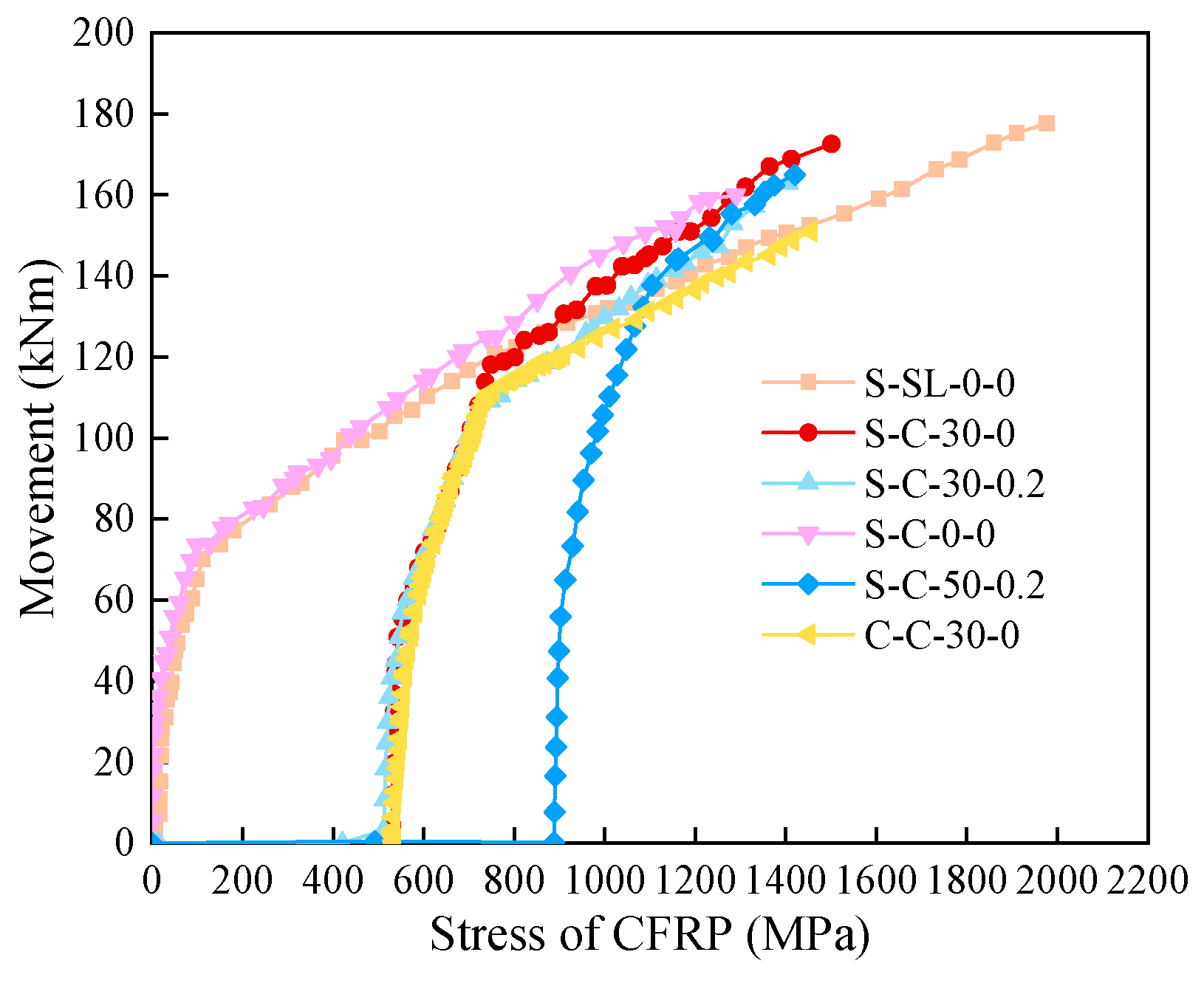
3.5. CFRP Tendon Stress Increment

For external prestressing tendon reinforcement, the stress increment in the external tendon is a key indicator of the flexural performance of the reinforced beam. The stress increment of CFRP external tendons corresponding to the increase in external moment was measured as shown in Figure 10. The curves of CFRP tendons exhibit similar shapes for all conditions during the elastic phase of the reinforced beams and show a linear relationship. When the yield moment is reached, the curve shows a turning point and the stress in the CFRP reinforcement increases sharply. When the stress in the CFRP tendon reaches the ultimate stress, the carbon tendon starts to rupture and at the same time the reinforced beam is damaged. For specimen S-SL-0-0, due to the form of the straight-line reinforcement arrangement, the strength of CFRP reinforcement is less affected, so the stress of CFRP reinforcement is higher, yet there is no significant enhancement of the corresponding external bending moment.

4. Theory of Flexural Bearing Capacity Calculation

In contrast to internally prestressed structures, which facilitate accurate estimates of structural response via sectional analysis, constructions incorporating exterior prestressing present additional complexity. The force analysis of the reinforced beam is shown in Figure 11. In beams that are reinforced with externally prestressed CFRP tendons, the strain variations in these tendons are not aligned perfectly with the deformations of the concrete. Moreover, the stress increments in these externally prestressed CFRP tendons are directly correlated with the overall deformations of the structure. Beams with lower initial prestressing levels, particularly those containing initial cracks, demonstrate greater mid-span ultimate deflections, resulting in a significant secondary effect. The aforementioned secondary effects diminish the extent to which CFRP reinforcement enhances the ultimate flexural bearing capacity of the test beams. Consequently, beams that have lower levels of initial prestress and existing initial cracks exhibit a minor decrease in their ultimate flexural capacity.
M u = f y · A s · h 0 x 2 + k 2 · f p s A p e · h p e x 2 Δ u ,
x = f y · A s f y · A s + f p s · A p e α 1 · f c · b .
The stress fps of the externally prestressed CFRP tendons in the limit state can be expressed as:
f p s = f p e + Δ f p s ,
Δ f p s = Δ L c f r p L c f r p · E c f r p .
As depicted in Figure 12, the deflection–moment behavior exhibited by the test beams can be approximated as a tri-linear response. Theoretically, after cracking occurs in a section, the moment of inertia of the cracked part applies only to the cracked portion, while the gross moment of inertia pertains to the section between the cracks. Nevertheless, this methodology is deemed impractical and incapable of guaranteeing a precise evaluation of the beam’s deflection, as the true rigidity of the beam falls within the range of EcIg and EcIcr. Currently, the standard ACI 440.4R [33] uses the effective moment of inertia approach for evaluating the deflection under a specified flexural moment. The definition of the effective moment of inertia, as stated in ACI 440.4R, can be expressed mathematically by Equation (5). When exceeding the cracking moment, the beam experiences discrete cracks, leading to variations in its flexural rigidity throughout its length. The effective moment of inertia essentially reflects this rigidity variation and represents the collective flexural rigidity of the beam as a whole. As the applied moment increases, the variable Ie represents a gradual shift from the initial moment of inertia Ig to the cracking moment of inertia Icr [15].
I e = M c r M a 3 I g + 1 M c r M a 3 I c r I g ,
y = y c r + y y + y a ,
y c r = M c r k 3 · f p e · A p e · h p e x 2 · L 0 2 · k 1 E c · I g ,
y y = M y M c r · L 0 2 · k 1 E c · I e ,
y a = M a M y · l 0 2 7 · k 1 · E c · I e ,
k 1 = a 2 L 0 ,
k 2 = 1 + a L 0 ,
k 3 = I c r I g ,
Δ l c f r p = 2 · h p e x · 2 y L 0 .
During the loading phase, cracks mainly appear in the mid-span pure flexural section, while there are fewer and narrower cracks in the shear span area. Owing to the “strong shear, weak flexural” design principle, deformations in the shear span region are negligible. Moreover, during the loading process, there is no relative sliding between the beam end reaction frame, deviator, and the test beam. It can be assumed that the length of the CFRP reinforcement remains unchanged, and the elongation of the CFRP tendon mainly occurs in the mid-span pure flexural section. Therefore, the elongation value of the CFRP tendon, Δlcfrp, can be calculated through Equation (13).
In theoretical calculations, when fps attains its ultimate strength, the CFRP reinforcement is considered fractured, with concurrent failure of the experimental beam. Based on the material test, the CFRP tendon has an ultimate strength of fps = 2123 MPa, According to the research results of Fu et al. [34], the ultimate strength of the CFRP tendon will decrease in a bent state. In this experiment, the radius of curvature for the deviator used is 1000 mm with a turning angle of 30°. It can be inferred that in a bent state, the CFRP tendon has an ultimate strength of around 0.68fps, equivalent to 1443 MPa. As shown in Figure 13, an iterative procedure was established to predict the flexural ultimate capacity of concrete beams reinforced with extracorporeal prestressed CFRP tendons, using the CFRP tendons reaching the ultimate tensile stress as the beam failure criterion. The results calculated from the theoretical equations typically have an error not exceeding 10% when compared to experimental data, and detailed results can be seen in Table 4.

5. Conclusions

In this research, externally prestressed CFRP tendons were utilized to strengthen six simply supported beams of 3.5 m length and two two-span continuous beams of 7 m length, aiming to evaluate the efficacy of prestressed carbon fiber reinforcements in augmenting the bending and shear resistance capabilities of concrete simply supported and continuous beams. The formula for calculating the beam’s bending load-carrying capacity was refined based on model test outcomes. Conclusions drawn from the experimental results and discussions are as follows:
  • Through the reinforcement of externally prestressed CFRP tendons, the bending load-bearing capacity of the test beams was significantly enhanced, the bending rigidity demonstrates an increase positively related to the external prestressing level. When compared with the contrast beam, the simply supported beams reinforced with CFRP tendons using bend and linear layouts saw increases in bending load-bearing capacity of approximately 160% and 170%, respectively; whereas, for the continuous beams strengthened with curved layout reinforcement, the bending load-bearing capacity was increased by approximately 113%. Under identical reinforcement conditions, the increase in bending and shear capacities of the simply supported beams with CFRP tendon reinforcement was greater than that of the continuous beams.
  • By comparing the strain of stirrups in the reinforced beams, it is observed that increasing the prestressing level of the CFRP tendons effectively enhances the shear capacity of the concrete beams. Notably, the contribution of bend-arranged reinforcement to the shear performance of the beam exceeds that of linear-arranged reinforcement. Under identical reinforcement parameters, the increase in shear capacity observed in simply supported beams outperforms that in continuous beams.
  • The prestress level of CFRP tendons and the pre-existing cracks have minimal influence on the ultimate bending capacity of concrete beams, but they noticeably influence the cracking moment and yielding moment of the test beams. The yielding load is positively correlated with the external prestress level, whereas pre-existing cracks lead to a decrease in carrying capacity in the reinforced beams.
  • Based on existing theories, modifications have been made to the bending load-bearing capacity formula. The correction formula takes into account the influence of cracking conditions and the form of prestressing tendon arrangement. The discrepancy between theoretical calculations and measured values is within 10%, proving its validity for beams externally prestressed using CFRP tendons.
The above conclusions will be confirmed by additional tests and finite element simulations to improve the reliability of the test results and to obtain design values with adequate safety factors that take into account a wider range of variability. However, further experimental work and theoretical studies are necessary to develop more rational and accurate prediction models covering various concrete strengths, internal longitudinal reinforcement, and FRP types.

Author Contributions

Conceptualization, Z.W.; methodology, Z.W.; software, Z.W.; validation, Z.W., H.J. and B.W.; formal analysis, Z.W.; investigation, Z.W. and H.J.; resources, Z.W. and H.J.; data curation, Z.W.; writing—original draft preparation, Z.W.; writing—review and editing, Z.W. and B.W.; visualization, Z.W. and B.W.; supervision, P.Z.; project administration, Z.W., H.J. and B.W.; funding acquisition, P.Z. All authors have read and agreed to the published version of the manuscript.

Funding

This research was funded by Zhejiang Province Public Welfare Projects (Grant No. LGF22E080023), IOT Technology Application Transportation Industry R&D Center (Hangzhou) (Grant No. 202213), and the National Natural Science Foundation of China (Grant No. 52078256).

Institutional Review Board Statement

Not applicable.

Informed Consent Statement

Not applicable.

Data Availability Statement

Data are contained within the article.

Conflicts of Interest

The authors declare that the research was conducted in the absence of any commercial or financial relationships that could be construed as a potential conflict of interest.

Nomenclature

f c Compressive strength of concrete A p e Cross-section area of CFRP tendon
f y Yield strengths of tensile rebar A s Cross-section area of compressive rebar
f y Yield strengths of compressive rebar A s Cross-section area of tensile rebar
f u Ultimate strength of rebar I g Gross section moment of inertia of the cross-section
f p e Initial prestress of the CFRP tendon I c r Cracking moment of inertia of the cross-section
f p s Ultimate strength of CFRP tendon I e Equivalent moment of inertia of the cross-section
Δ f p s Stress increment of CFRP tendon E Modulus of elasticity
M c r Crack moment of reinforced beam E c Modulus of elasticity of concrete
M y Yield moment of reinforced beam E c f r p Modulus of elasticity of CFRP tendon
M u Ultimate moment of reinforced beam α 1 Coefficient for the concrete strength realization, taken as 1.0
M a Moment applied on reinforced beam b Width of the test beam’s cross-section
y u Ultimate mid-span deflection of reinforced beam Δ u The change in the distance between the CFRP tendon and the bottom of the beam due to the second-order effect
y a Deflection increment of the test beam after yielding of reinforcement L 0 Span of the test beam
y Mid-span deflection corresponding to M a L c f r p Length of CFRP tendon
y y Mid-span deflection of reinforced beams at yield stage Δ L c f r p Amount of change in length of CFRP bars
y c r Mid-span deflection of reinforced beams at cracking stage h 0 Height from the centroid of the tensile rebar section to the edge of the compressed concrete zone
k 1 Coefficient for load effects, taking a value of 0.25 for single-point loading h p e Height from the centroid of the CFRP tendon section to the edge of the compressed concrete zone
k 2 Coefficient related to the layout shape of the prestressed tendons x Height of the compression area of the section
k 3 Reduction coefficient for pre-cracking ω m a x Maximum permissible crack width
a Distance between loading points

References

  1. Yang, Z.; Yingfeng, L. Experimental and Theoretical Study on Shear Behavior of Damaged RC Beams Strengthened by High Strength Steel Wires Mesh-UHPC. Highw. Eng. 2021, 186, 107834. [Google Scholar]
  2. Burningham, C.A.; Pantelides, C.P.; Reaveley, L.D. Repair of Prestressed Concrete Beams with Damaged Steel Tendons Using Post-Tensioned Carbon Fiber-Reinforced Polymer Rods. ACI Struct. J. 2014, 111, 387–396. [Google Scholar] [CrossRef]
  3. Elrefai, A.; West, J.; Soudki, K. Fatigue of reinforced concrete beams strengthened with externally post-tensioned CFRP tendons. Constr. Build. Mater. 2012, 29, 246–256. [Google Scholar] [CrossRef]
  4. Havez, A.A.; Al-Mayah, A. Flexural Strengthening of Concrete Structures Using Externally Bonded and Unbonded Prestressed CFRP Laminates: A Literature Review. J. Compos. Constr. 2023, 27, 03123001. [Google Scholar] [CrossRef]
  5. Abdallah, M.; Al Mahmoud, F.; Khelil, A.; Mercier, J.; Almassri, B. Assessment of the flexural behavior of continuous RC beams strengthened with NSM-FRP bars, experimental and analytical study. Compos. Struct. 2020, 242, 112127. [Google Scholar] [CrossRef]
  6. Ghallab, A.; Beeby, A.W. Factors affecting the external prestressing stress in externally strengthened prestressed concrete beams. Cem. Concr. Compos. 2005, 27, 945–957. [Google Scholar] [CrossRef]
  7. Le, T.D.; Pham, T.M.; Hao, H.; Li, H. Behavior of Precast Segmental Concrete Beams Prestressed with External Steel and CFRP Tendons. J. Compos. Constr. 2020, 24, 04020053. [Google Scholar] [CrossRef]
  8. Panahi, M.; Zareei, S.A.; Izadi, A. Flexural strengthening of reinforced concrete beams through externally bonded FRP sheets and near surface mounted FRP bars. Case Stud. Constr. Mater. 2021, 15, e00601. [Google Scholar] [CrossRef]
  9. El-Hacha, R. Prestressing Concrete Structures with FRP Tendons (ACI 440.4R-04). In Proceedings of the Structures Congress, New York, NY, USA, 20–24 April 2005; pp. 1–8. [Google Scholar]
  10. Schmidt, J.W.; Bennitz, A.; Täljsten, B.; Goltermann, P.; Pedersen, H. Mechanical anchorage of FRP tendons—A literature review. Constr. Build. Mater. 2012, 32, 110–121. [Google Scholar] [CrossRef]
  11. Pang, M.; Li, Z.; Lou, T. Numerical Study of Using FRP and Steel Rebars in Simply Supported Prestressed Concrete Beams with External FRP Tendons. Polymers 2020, 12, 2773. [Google Scholar] [CrossRef]
  12. Peng, F.; Xue, W. Analytical Approach for Flexural Capacity of FRP Prestressed Concrete T-Beams with Non-Prestressed Steel Bars. J. Compos. Constr. 2018, 22, 04018063. [Google Scholar] [CrossRef]
  13. Bennitz, A.; Schmidt, J.W.; Nilimaa, J.; Täljsten, B.; Goltermann, P.; Ravn, D.L. Reinforced concrete T-beams externally prestressed with unbonded carbon fiber-reinforced polymer tendons. ACI Struct. J. 2012, 109, 521–530. [Google Scholar] [CrossRef]
  14. Lou, T.; Lopes, S.M.R.; Lopes, A.V. Numerical analysis of behaviour of concrete beams with external FRP tendons. Constr. Build. Mater. 2012, 35, 970–978. [Google Scholar] [CrossRef]
  15. Pirayeh Gar, S.; Mander, J.B.; Hurlebaus, S. Deflection of FRP Prestressed Concrete Beams. J. Compos. Constr. 2018, 22, 04017049. [Google Scholar] [CrossRef]
  16. Akbarzadeh Bengar, H.; Shahmansouri, A.A. A new anchorage system for CFRP strips in externally strengthened RC continuous beams. J. Build. Eng. 2020, 30, 101230. [Google Scholar] [CrossRef]
  17. Buyle-Bodin, F.; David, E.; Ragneau, E. Finite element modelling of flexural behaviour of externally bonded CFRP reinforced concrete structures. Eng. Struct. 2002, 24, 1423–1429. [Google Scholar] [CrossRef]
  18. Weichen Xue, Y.T.; Fei, P. Experimental Study on Damaged Prestressed Concrete Beams Using External Post-Tensioned Tendons. ACI Struct. J. 2020, 117, 159–168. [Google Scholar] [CrossRef]
  19. Frosch, R.J. Contribution of Concrete to Shear Resistance. In Proceedings of the Structures Congress, Austin, TX, USA, 30 April–2 May 2009; pp. 1579–1586. [Google Scholar] [CrossRef]
  20. Tureyen, A.K.; Frosch, R.J. Shear tests of FRP-reinforced concrete beams without stirrups. Struct. J. 2002, 99, 427–434. [Google Scholar] [CrossRef]
  21. Tureyen, A.K.; Frosch, R.J. Concrete shear strength: Another perspective. Struct. J. 2003, 100, 609–615. [Google Scholar] [CrossRef]
  22. Dong, J.; Wang, Q.; Guan, Z. Structural behaviour of RC beams with external flexural and flexural–shear strengthening by FRP sheets. Compos. Part B Eng. 2013, 44, 604–612. [Google Scholar] [CrossRef]
  23. Hawileh, R.A.; Nawaz, W.; Abdalla, J.A.; Saqan, E.I. Effect of flexural CFRP sheets on shear resistance of reinforced concrete beams. Compos. Struct. 2015, 122, 468–476. [Google Scholar] [CrossRef]
  24. Shang, W.; Ning, X.; Liu, J.; Liu, J. Failure analysis and evaluation for cracked concrete beam reinforced with CFRP. Theor. Appl. Fract. Mech. 2024, 129, 104222. [Google Scholar] [CrossRef]
  25. Sun, Y.; Fu, W.; Chen, X.; Zhang, Z.; Yu, W.; Li, S. Theoretical and experimental investigations into flexural behavior of existing reinforced concrete beams strengthened by CFRP bars. J. Build. Eng. 2023, 77, 107528. [Google Scholar] [CrossRef]
  26. Naaman, A.E.; Alkhairi, F.M. Stress at ultimate in unbonded post-tensioning tendons: Part 2--proposed methodology. Struct. J. 1992, 88, 683–692. [Google Scholar] [CrossRef]
  27. Aravinthan, T. Flexural behavior of externally prestressed beams with large eccentricities. Proc. JCI 1999, 21, 949–954. [Google Scholar]
  28. Feng, X.; Lihua, X.; Jian, D.; Le, H. Experimental study on flexural behavior of concrete T-beams strengthened with externally prestressed CFRP tendons. China Civ. Eng. J. 2014, 47, 43–50. [Google Scholar] [CrossRef]
  29. Li-hua, X.; Feng, X.; Le, H. Calculation method on short-term deflection of concrete T-beams strengthened with externally prestressed CFRP tendons. Eng. Mech. 2015, 32, 43–49. [Google Scholar]
  30. Wang, X.; Dai, H.; Ding, H.; Ye, J. Experimental study on flexural behaviour of concrete beams prestressed with external CFRP tendons. J. Southeast Univ. 2009, 39, 557–562. [Google Scholar]
  31. Abushanab, A.; Alnahhal, W.; Farraj, M. Structural performance and moment redistribution of basalt FRC continuous beams reinforced with basalt FRP bars. Eng. Struct. 2021, 240, 112390. [Google Scholar] [CrossRef]
  32. GB50010-2010; Code for Design of Architecture & Concrete Structures. China Architecture & Building Press: Beijing, China, 2010.
  33. ACI 440.4R-04; Prestressing Concrete with FRP Tendons. American Concrete Institute: Farmington Hills, MI, USA, 2004; p. 35.
  34. Fu, J.; Zeng, T.; Wang, B.; Zhuge, P.; Xia, J.; Cai, W. The Interfacial Friction Loss of Prestressed Carbon-Fiber Tendons in a Bending State. Buildings 2022, 13, 99. [Google Scholar] [CrossRef]
Figure 1. Experimental beam parameter illustration: (a) Reinforcement with straight CFRP tendons in a simply supported beam; (b) reinforcement with bent CFRP tendons in a simply supported beam; (c) reinforcement with bent CFRP tendons in a continuous beam; (d) bent arrangement carbon fiber reaction frame; (e) deviator; (f) straight-line arrangement carbon fiber reaction frame.
Applsci 14 01237 g001aApplsci 14 01237 g001b
Figure 2. Stress–strain curves of materials: (a) CFRP tendon; (b) concrete; (c) reinforcing bars with a diameter of 16 mm; (d) reinforcing bars with a diameter of 8 mm.
Applsci 14 01237 g002
Figure 3. Schematic illustration of loading and testing apparatus: (a) loading and testing setup for simply supported beam; (b) loading and testing setup for continuous beam.
Applsci 14 01237 g003
Figure 4. Failure modes of concrete beams; (a) SCB; (b) S-SL-0-0; (c) S-C-30-0; (d) S-C-30-0.2; (e) S-C-0-0; (f) S-C-50-0.2; (g) CCB; (h) C-C-30-0.
Applsci 14 01237 g004aApplsci 14 01237 g004b
Figure 5. Deflection–moment curves: (a) Deflection–moment curves in the span of a simply supported beam; (b) comparison of deflection–moment curves in the span of a continuous beam and a simply supported beam.
Applsci 14 01237 g005
Figure 6. Measured crack diagram of the specimen S-C-50-0.2: (a) 90 kN·m; (b) 138 kN·m; (c) 147 kN·m.
Applsci 14 01237 g006
Figure 7. Comparison of crack widths: (a) Curve of maximum crack width for simply supported beams; (b) comparison of crack widths between continuous beams and simply supported beams.
Applsci 14 01237 g007
Figure 8. Curve of stirrup strain–flexural moment in the support region: (a) Curve of stirrup strain–flexural moment for simply supported beams; (b) comparison of stirrup strain–flexural moment curves between continuous beams and simply supported beams.
Applsci 14 01237 g008
Figure 9. Concrete strain distribution in mid-span section: (a) Specimen S-C-0-0; (b) Specimen C-C-30-0.
Applsci 14 01237 g009
Figure 10. Moment–CFRP tendon stress curve.
Applsci 14 01237 g010
Figure 11. Stress condition of the cracked cross-section.
Applsci 14 01237 g011
Figure 12. The flexural moment–deflection relationship curve.
Applsci 14 01237 g012
Figure 13. Iterative calculation flowchart for ultimate bending moment.
Applsci 14 01237 g013
Table 1. Sample number and parameter table.
Specimen No.Prestressing Level of
External Tendons (%)
Carbon Reinforcement
Arrangement
Pre-Cracked StateSupport Conditions
SCB--Un-pre-crackedSimply Supported
S-SL-0-00LinearUn-pre-crackedSimply Supported
S-C-30-030CurvedUn-pre-crackedSimply Supported
S-C-30-0.230CurvedPre-cracking 0.2 mmSimply Supported
S-C-0-00CurvedUn-pre-crackedSimply Supported
S-C-50-0.250CurvedPre-cracking 0.2 mmSimply Supported
CCB--Un-pre-crackedContinuous
C-C-30-030CurvedUn-pre-crackedContinuous
Table 2. Material properties of concrete, steel reinforcement, and CFRP tendons.
MaterialTypefc (MPa)fy (MPa)fu (MPa)E (GPa)
ConcreteC4040.9--32.8
RebarD = 16 mm-447.8604.5196.7
D = 8 mm-457.7619.7201.3
CFRP tendonD = 10 mm--2123160.5
Table 3. Test results for the specimens.
Beam NO.PrestressingCracking/ReopeningYieldingUltimateDamage Mode
fpe
(MPa)
Mcr
(kN·m)
ycr
(mm)
My
(kN·m)
yy
(mm)
Mu
(kN·m)
yu
(mm)
SCB-21.31.356.19.165.663.2Flexural damage
S-SL-0-0729.11.2100.711.3177.657.2Concrete crushing
S-C-30-052447.11.5117.810.7172.835.1CFRP tendon rupture
S-C-30-0.251339.61.6107.91116842.6CFRP tendon rupture
S-C-0-0923.21.275.210.8160.654.5Concrete crushing
S-C-50-0.290747.11.2140.212.1166.826.4CFRP tendon rupture
CCB-29.72.571.613.175.171.3Flexural damage
C-C-30-053141.11.72100.810.9159.634.6CFRP tendon rupture
Table 4. Iterative calculation flowchart for ultimate bending moment.
Beam NO. M u e
(kN·m)
M u p
(kN·m)
M u p M u e Δ u e
(mm)
Δ u p
(mm)
Δ u p Δ u e f p s e f p s p f p s p f p s e
S-L-0-0177.6178.21.00457.254.70.956197721231.073
S-C-30-0172.8169.10.97935.134.00.969150814430.957
S-C-30-0.2168166.90.99342.640.80.958142514431.012
S-C-0-0160.6163.41.01754.552.40.961139414431.035
S-C-50-0.2166.8171.71.02926.427.31.034144814430.996
C-C-30-0159.6174.31.09234.631.60.914145514430.992
Average 1.019 0.965 1.011
Standard
deviation
0.0364 0.0354 0.0363
The subscript e in the table denotes experimental measured data and p denotes theoretical predicted values.
Disclaimer/Publisher’s Note: The statements, opinions and data contained in all publications are solely those of the individual author(s) and contributor(s) and not of MDPI and/or the editor(s). MDPI and/or the editor(s) disclaim responsibility for any injury to people or property resulting from any ideas, methods, instructions or products referred to in the content.

